EP3516440B2 - Système de microscope - Google Patents
Système de microscope Download PDFInfo
- Publication number
- EP3516440B2 EP3516440B2 EP17781403.5A EP17781403A EP3516440B2 EP 3516440 B2 EP3516440 B2 EP 3516440B2 EP 17781403 A EP17781403 A EP 17781403A EP 3516440 B2 EP3516440 B2 EP 3516440B2
- Authority
- EP
- European Patent Office
- Prior art keywords
- scanning
- operating state
- functional unit
- sample
- microscope
- Prior art date
- Legal status (The legal status is an assumption and is not a legal conclusion. Google has not performed a legal analysis and makes no representation as to the accuracy of the status listed.)
- Active
Links
Images


Classifications
-
- G—PHYSICS
- G02—OPTICS
- G02B—OPTICAL ELEMENTS, SYSTEMS OR APPARATUS
- G02B21/00—Microscopes
- G02B21/0004—Microscopes specially adapted for specific applications
- G02B21/002—Scanning microscopes
- G02B21/0024—Confocal scanning microscopes (CSOMs) or confocal "macroscopes"; Accessories which are not restricted to use with CSOMs, e.g. sample holders
- G02B21/0036—Scanning details, e.g. scanning stages
- G02B21/0048—Scanning details, e.g. scanning stages scanning mirrors, e.g. rotating or galvanomirrors, MEMS mirrors
-
- G—PHYSICS
- G02—OPTICS
- G02B—OPTICAL ELEMENTS, SYSTEMS OR APPARATUS
- G02B21/00—Microscopes
- G02B21/0004—Microscopes specially adapted for specific applications
- G02B21/002—Scanning microscopes
- G02B21/0024—Confocal scanning microscopes (CSOMs) or confocal "macroscopes"; Accessories which are not restricted to use with CSOMs, e.g. sample holders
- G02B21/0032—Optical details of illumination, e.g. light-sources, pinholes, beam splitters, slits, fibers
-
- G—PHYSICS
- G02—OPTICS
- G02B—OPTICAL ELEMENTS, SYSTEMS OR APPARATUS
- G02B21/00—Microscopes
- G02B21/06—Means for illuminating specimens
- G02B21/08—Condensers
- G02B21/082—Condensers for incident illumination only
-
- G—PHYSICS
- G02—OPTICS
- G02B—OPTICAL ELEMENTS, SYSTEMS OR APPARATUS
- G02B21/00—Microscopes
- G02B21/36—Microscopes arranged for photographic purposes or projection purposes or digital imaging or video purposes including associated control and data processing arrangements
-
- G—PHYSICS
- G02—OPTICS
- G02B—OPTICAL ELEMENTS, SYSTEMS OR APPARATUS
- G02B21/00—Microscopes
- G02B21/36—Microscopes arranged for photographic purposes or projection purposes or digital imaging or video purposes including associated control and data processing arrangements
- G02B21/365—Control or image processing arrangements for digital or video microscopes
- G02B21/367—Control or image processing arrangements for digital or video microscopes providing an output produced by processing a plurality of individual source images, e.g. image tiling, montage, composite images, depth sectioning, image comparison
Definitions
- the invention relates to a microscope system with a light sheet microscopic functional unit that is designed to image a sample in a first operating state of the microscope system using a light sheet-like illumination light distribution, and a scanning microscopic functional unit that is designed to image the sample in a second operating state of the microscope system using a point-like illumination light distribution .
- So-called light disc or light sheet microscopes are known from the prior art, which generate a light sheet-like illumination light distribution in order to illuminate only a thin layer in the sample.
- light sheet microscopes which have two separate lenses for illumination and detection on the sample side
- light sheet microscopes are now also being used that make do with a single lens facing the sample.
- OPM oblique plane microscope
- a variation of a sloping plane microscope is known, which enables a lateral scanning, ie scanning perpendicular to the direction of light propagation, of the sample volume with the aid of two deflection elements.
- Such a microscope is also referred to as a SCAPE microscope (SCAPE: "swept confocally-aligned planar excitation").
- a light sheet microscope images the sample by means of a light sheet-like illumination light distribution
- the sample is imaged point by point in conventional scanning microscopes, eg confocal or multiphoton microscopes.
- Such a scanning microscope accordingly generates a point-like illumination light distribution, which is moved over the sample with the aid of scanning elements in order to scan the same along two orthogonal scanning axes with the illumination light distribution.
- Both inclined plane microscopes and scanning microscopes each of which is equipped with one or more scanning elements in order to scan the sample with the respective illumination light distribution, require a telescope system that maps the exit pupil of the objective lens on the sample in the form of a real image onto the respective scanning element.
- Such a telescope system must be extremely low in aberrations for both orthoscopic and conoscopic images in order to ensure adequate imaging quality. This makes it comparatively expensive.
- the object of the invention is to specify a microscope system and a method for imaging a sample using a light microscope, which allows both light sheet microscopy and raster microscopy to be used with comparatively little technical effort.
- the microscope system comprises a light sheet microscopic functional unit, which is designed to image a sample in a first operating state of the microscope system by means of a light sheet-like illumination light distribution, a scanning microscopic functional unit, which is designed to form the sample in a second operating state of the microscope system by means of a point-like illumination light distribution, a first Scanning element that is designed to scan the sample in the first operating state with the light sheet-like illumination light distribution generated by the light-sheet-microscopic functional unit and to scan the sample in the second operating state with the point-like illumination light distribution generated by the scanning-microscopic functional unit, a second scanning element that is designed to scan the sample in the second operating state with the punctiform illumination light distribution generated by the scanning microscopic functional unit in one axis and thereby in the second operating state, together with the first scanning element, to effect a two-axis scanning of the sample with the punctiform illumination light distribution generated by the scanning microscopic functional unit, and a control unit configured to switch between the first operating state and
- the invention makes use of the fact that both an inclined plane microscope, e.g. an OPM or a SCAPE microscope, and a scanning microscope of the type mentioned at the outset have a uniaxial scanning element, i.e. an element that causes light to be scanned along a single scanning axis.
- this element referred to as a scanning element, is used to move the light sheet-like illumination light distribution for volume imaging transversely to the direction of propagation of the illumination light.
- the scanning microscope it effects one of the two usually orthogonal scanning movements of the punctiform light distribution.
- This element can thus be used both in the light sheet microscopic functional unit and in the raster microscopic functional unit for scanning illumination of the sample.
- the first scanning element alone is sufficient to scan the sample with the illuminating light.
- the invention provides, in the second operating state of the microscope system, which is used for raster microscopic imaging by means of a point-like illumination light distribution, to use a second scanning element in addition to the first scanning element, which also causes uniaxial scanning.
- the two scanning axes are preferably orthogonal to one another in the second operating state. The two uniaxially acting scanning elements thus form a two-axis scanning system in their interaction.
- the microscope system Via the first scanning element used in the two operating states according to the invention, the microscope system combines the two application-related complementary imaging methods of a light sheet microscope and a point-by-point scanning microscope. Switching between these two imaging methods is coordinated by a control unit.
- This can, for example, be designed in such a way that it is solely responsible for controlling the scanning elements and otherwise leaves the control to separate control devices, which in particular control the two different imaging processes.
- the control unit can also control the overall operation of the microscope system, i.e. also all imaging processes.
- the first scanning element and the second scanning element preferably form a telecentric scanning system in the second operating state of the microscope system.
- the light sheet microscopic functional unit and the scanning microscopic functional unit have a common lens facing the sample, each for illumination and detection. This enables a particularly compact construction of the microscope system according to the invention.
- the light sheet microscopic functional unit and the scanning microscopic functional unit have a common telescope optics, which images an exit pupil of the objective onto the first scanning element. Since telescope optics that can be used to generate a pupil image, as mentioned at the outset, have particularly low levels of aberrations and are therefore comparatively expensive, the joint use of the telescope optics offers a considerable cost advantage.
- the microscope system preferably has a microscope stand that carries the common objective and has a connection element to which the common telescope optics can be connected.
- the microscope system in the manner of a microscope module, can be combined particularly easily with an existing microscope stand, e.g. an upright microscope, an inverted microscope or a fixed-stage microscope.
- an existing microscope stand e.g. an upright microscope, an inverted microscope or a fixed-stage microscope.
- the light sheet microscopic functional unit and the raster microscopic functional unit have the common telescope optics, so that only a single connection element has to be provided for coupling to the microscope stand.
- the first scanning element and the second scanning element are each designed, for example, as a galvanometer mirror or microelectromechanical mirror (MEMS).
- the first scanning element can be tilted about a first tilting axis and the second scanning element can be tilted about a second tilting axis, which is preferably perpendicular to the first tilting axis.
- the first scanning element can be tilted within a first tilting angle range in the first operating state and within a second tilting angle range, which is different from the first tilting angle range, in the second operating state.
- the microscope system preferably contains a switching element that can be controlled by a control unit for switching between the first operating state and the second operating state.
- the switchover element is formed, for example, by the first deflection element, which can be tilted for switching the operating state between a tilted position within the first tilting angle range and a tilted position within the second tilting angle range.
- This embodiment makes use of the fact that, viewed from the perspective of the telescope optics imaging the objective pupil onto the first scanning element, there are two tilt angle ranges accessible to the first scanning element, which can be assigned to the two operating states.
- This makes it possible for the first scanning element, on the one hand, to carry out the scanning required for the application along the first scanning axis, and, on the other hand, to select the appropriate tilting angle range in order to achieve the desired operating state to realize.
- the switching element is formed by a light deflection element that is provided separately from the first scanning element.
- This light deflection element is, for example, a mirror or prism that can be moved into the beam path and removed from it. It can also be designed in the form of a deflection element which remains in the beam path and which is adjusted, for example tilted, to select the operating state.
- This embodiment has the further advantage that the telescope optics, which images the objective pupil onto the first scanning element, only have to be provided once and occupy only one adaptation point on the microscope if the invention is designed as a module for a conventional microscope.
- the light sheet microscopic functional unit comprises an illumination optics, which is designed to generate the light sheet-like illumination light distribution in an intermediate image space, a telecentric transport optics on both sides, which is designed to transmit the light sheet-like illumination light distribution generated in the intermediate image space into the sample, and one with the light sheet-like illumination light distribution to image the illuminated area of the sample as an intermediate image in the intermediate image space, and detection optics, which are designed to image the intermediate image generated in the intermediate image space onto a detector, wherein the optical axes of the illumination optics, the transport optics and the detection optics intersect in the intermediate image space, and wherein the first scanning element is arranged in the transport optics and is designed, in the first operating state, to move the light sheet-like illumination light distribution in the sample transversely, preferably perpendicularly, to the optical axis of the transport optics.
- the aforementioned transport optics which includes the telescope system shared by the light sheet microscopic functional unit and the scanning microscopic functional unit, represents an intermediate imaging system that has the properties required for volume imaging, namely a magnification that corresponds to the refractive index ratio between the sample space and the intermediate space, in order to ensure correct imaging to ensure the aperture angle, and a bilateral, i.e. both object-side and image-side, telecentricity, i.e. a lateral magnification which is independent of the position along the optical axis.
- the scanning microscopic functional unit forms a confocal microscope or a multiphoton microscope.
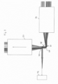
- FIG 1 shows a schematic representation of the structure of a microscope system 10, which represents an embodiment of the invention.
- the microscope system 10 comprises an in figure 1 a light sheet microscopic engine, generally designated 12, and a scanning microscopic engine, generally designated 14.
- the microscope system 10 provides two operating states that can be set as desired, namely a first operating state in which the light sheet microscopic functional unit 12 is used in the manner of a slanted plane microscope to image a sample 16 using a light sheet-like illumination light distribution, and a second operating state in which the scanning microscopic functional unit 14 Sample 16 using a point-like illumination light distribution.
- the light sheet microscopic functional unit 12 is first described below.
- the light sheet microscopic functional unit 12 comprises an illumination optics 18, a transport optics 20 and a detection optics 22, the optical axes O 1 , O 2 , or O 3 in an in figure 1 designated with 24 converge, ie intersect there.
- the purpose of the illumination optics 18 is to focus the illumination light 30 fed to it from a light source 28 into the intermediate image space 24 in such a way that an illumination light distribution is generated there in the manner of a light sheet.
- This light sheet generated in the intermediate image space 24 is then imaged by the transport optics 22 in the sample 16, so that a region of the sample 16 is illuminated with the light sheet and excited to emit fluorescence radiation.
- the fluorescence radiation emitted by the sample 16 again reaches the transport optics 20, which thus images the sample area illuminated with the light sheet as an intermediate image in the intermediate image space 24.
- the intermediate image generated in the intermediate image space 24 of the illuminated Sample area is finally imaged by the detection optics 22 on a detection surface 32 of a detector 34.
- the illumination optics 18 successively contain a beam conditioning unit 36, an adjustment element 38, an ocular lens system 40, a further adjustment element 42, a tube lens element 44 and an illumination objective 46, which faces the intermediate image space 24.
- the beam processing unit 36 contains a cylindrical lens 48 which, in cooperation with the illumination objective 46, is part of an anamorphic optical system which has the function of generating the light sheet in the desired form from the illumination light 30 emitted by the light source 28 in the intermediate image space 24.
- the cylindrical lens 48 focuses the illumination light 30 into the image of the pupil of the illumination objective 46 generated by the ocular lens system 40 and the tube lens system 44.
- the tube lens system 44 and the eyepiece lens system 40 thus form a Galilean telescope with a real intermediate image.
- the two adjustment elements 38 and 42 contained in the illumination optics 18 form an adjustment device that makes it possible to adjust the light sheet relative to the detection surface 32 of the detector 34, more precisely, relative to the image of the detection surface 32 generated by the detection optics 22 in the intermediate image space 24 , on which the light sheet is superimposed.
- the adjusting element 42 is arranged in a plane which is conjugate to an image plane of the illumination objective 46 . Accordingly, the angle at which the illuminating light 30 exits the illuminating lens 46 is changed by tilting the adjusting element 42 .
- the adjustment element 38 is arranged in a plane which is conjugate to the pupil plane of the illumination objective 46 . The position of the illumination light 30 emerging from the illumination lens 46 can thus be adjusted by the adjustment element 38 .
- the two adjustment elements 38 and 42 thus allow the position and angle of the light sheet to be adjusted independently of one another.
- the illumination optics 18 can generate additional, in figure 1 contain elements not explicitly shown, for example a field stop and/or an aperture stop.
- the field stop has the function of limiting the light sheet in the direction in which it is expanded.
- the aperture stop is used to limit the opening angle with which the light sheet is focused.
- the transport optics 20 contain an objective 50, a tube lens system 52, an ocular lens system 54, a further ocular lens system 56, a further tube lens system 58, a deflection element 60, an afocal system 62 and an intermediate imaging lens 64. Both the tube lens system 52 and the The ocular lens system 48 as well as the tube lens system 58 and the ocular lens system 56 each form a Galileo telescope optic.
- the transport optics 20 are designed as a double-sided telecentric optical system.
- the afocal system 62 contained in the transport optics 20 is used to adapt the magnification to the refractive index ratio between the sample space and the intermediate image space 24, which is required for the desired volume image transport. Telescope optics 56 are coupled via a connecting element 53 to a microscope stand 55 on which objective 50 is held.
- the light sheet microscopic functional unit 12 in the transport optics 20 contains a first scanning element 66, which is designed, for example, as a galvanometer mirror or MEMS mirror.
- the sensing element 50 is pivotable about a tilting axis 68 which, with reference to FIG figure 2 specified coordinate system coincides with the z-axis, tiltable.
- the scanning element 66 serves to scan the sample 16 laterally, ie transversely to the optical axis of the objective 50 with the light sheet.
- the scanning element 66 is tilted about the tilting axis 68 within a predetermined first tilting angle range.
- the scanning element 66 is arranged at a point at which the telescope optics 56 generates a real image of an exit pupil 70 of the objective 50 . In other words, the telescope optics 56 thus images the exit pupil 70 onto the first scanning element 66 .
- the detection optics 22 contain a detection objective 72 facing the intermediate image space 24 and a tube lens system 74.
- the intermediate image of the sample area illuminated with the light sheet, which is generated by the transport optics 20 in the intermediate image space 24, is imaged on the detector surface 32 of the detector 40 via the detection objective 72 and the tube lens system 74 .
- the illumination optics 18, the transport optics 20 and the detection optics 22 of the light sheet microscopic functional unit 12 are aligned with one another such that their optical axes O 1 , O 2 , O 3 converge in the intermediate image space 24 .
- the illumination light 30 generated by the light source 28 is coupled into the transport optics 20 as it were by a geometric combination in the area of the intermediate image, which makes it possible to dispense with dichroic beam splitter elements in the area of the transport optics 20 .
- the imaging performance of the Transport optics 20 detrimental pupil displacement can be reliably avoided.
- the scanning microscopic functional unit 14 of the microscope system 10, which is put into operation in the second operating state, is described below.
- the raster microscopic functional unit 14 uses the objective 50 facing the sample 16 and the telescope optics 56 formed from the tube lens system 52 and the ocular lens system 54.
- the first scanning element 66 is also used by the raster microscopic functional unit 14 in the second operating state. This means that the two functional units 12, 14 of the microscope system 10 have shared components in the form of the lens 50, the telescope optics 56 and the first scanning element 66.
- the scanning microscopic functional unit 14 has an excitation/detection module 72 that is spatially separate from the light sheet microscopic functional unit 12.
- the scanning microscopic functional unit 14 also contains a second scanning element 74, which alone in the enlarged partial view figure 2 you can see.
- the second scanning element 74 is also implemented, for example, as a single-axis galvanometer mirror or MEMS mirror.
- the second scanning element 74 can be tilted about a tilting axis 76 which is orthogonal to the tilting axis 68 of the first scanning element 66 .
- the presentation in the figures 1 and 2 is greatly simplified.
- the second scanning element 76 relative to the plane of the drawing figure 2 is inclined, for example by 45 degrees.
- the beam path between the second scanning element 74 and the excitation/detection module 72 does not run in the plane of the drawing, but out of it or into it.
- components that are not explicitly shown can be present, such as in particular additional telescope optics, through which a further real image of the exit pupil 70 of the lens 50 can be generated. This makes it possible to position the second scanning element 74, which is to be located at the location of this pupil image, in the beam path of the functional unit 14 of a scanning microscope as desired.
- the first single-axis scanning element 66 and the second single-axis scanning element 76 form a telecentric two-axis scanning system that can be used to scan the sample 16 with the point-like illumination light distribution generated in the scanning microscopic functional unit 14 in two axes, i.e. along two preferably orthogonal to scan scanning axes. Both scanning elements 66 and 76 forming this two-axis scanning system are conjugate to the exit pupil 70 of the lens 50.
- the first scanning element 66 has the function, in cooperation with the second scanning element 74, of ensuring a two-axis scanning of the sample 16 with the point-like illumination light distribution.
- the first scanning element 68 is tilted about the tilting axis 68 within a second tilting angle range, which differs from the first tilting angle range used in the first operating state.
- first scanning element 66 offers the possibility of using the first scanning element 66 not only for the actual scanning process, which is carried out in the first or in the second operating state, but also as an element for switching between the first operating state and the second operating state. If the first scanning element 66 is in a tilted position that lies within the first tilting angle range, then the first scanning element 66 in the arrangement shown is automatically switched to the light sheet microscopic functional unit 12, as a result of which the first operating state is realized. If the scanning element is then tilted into the second tilt angle range, it is connected to the scanning microscopic functional unit 14, as a result of which the second operating state is selected.
- the microscope system 10 also has a control unit 87, which controls the switching of the operating states by a corresponding activation of the first scanning element 66.
- the control unit 87 can be designed in such a way that it also controls some other or even all operating processes of the microscope system 10 .
- FIG 3 shows a modified embodiment, in which a separate switching element is used for switching between the two operating states 78 is provided.
- the switching element 78 is, for example, a mirror which has a mirror surface 79 facing the second scanning element 66 and is introduced into the beam path between the two ocular lens systems 54, 56 in order to activate the scanning microscopic functional unit 14, i.e. to set the second operating state . If the mirror 78 is removed from the beam path, then the microscope system 10 is in the first operating state.
- a further single-axis scanning element for example in the form of a galvanometer mirror or a MEMS mirror, in the illumination optics 18 of the light sheet microscopic functional unit 12 for light sheet generation instead of the cylinder mirror 48 .
- a scanning element can be arranged, for example, at the point at which, in the exemplary embodiment figure 1 the adjusting element 38 is located.
- the scanning element then effects a scanning movement of the illumination light 30, by which the desired light sheet is built up sequentially.
- the control unit 87 then ensures that the operation of this scanning element is synchronized with the other system components, in particular with the first scanning element 66 .
- the further scanning element additionally present in the illumination optics 18 could be used in the same way for the functional coupling of a functional unit that scans point by point, as is done further above in the exemplary embodiment according to FIGS Figures 1 to 3 for the first sensing element 66 is described. Accordingly, a tilting angle range of this further scanning element that is not used for light sheet generation could be used corresponding to the second tilting angle range of scanning element 66 for the raster microscopic scanning and possibly also for switching between the two operating states.
Landscapes
- Physics & Mathematics (AREA)
- Chemical & Material Sciences (AREA)
- Analytical Chemistry (AREA)
- General Physics & Mathematics (AREA)
- Optics & Photonics (AREA)
- Engineering & Computer Science (AREA)
- Multimedia (AREA)
- Computer Vision & Pattern Recognition (AREA)
- Microscoopes, Condenser (AREA)
Claims (13)
- Système de microscopie (10) comprenant :- une unité fonctionnelle de microscopie à nappe de lumière (12) qui éclaire et reproduit un échantillon (16) dans un premier état de fonctionnement du système formant microscope (10) avec une distribution de lumière d'éclairage en forme de nappe de lumière,- une unité fonctionnelle de microscopie à balayage (14) qui éclaire et reproduit l'échantillon (16) dans un deuxième état de fonctionnement du système de microscopie (10) avec une distribution de lumière d'éclairage ponctuelle,- un premier élément de balayage (66) qui balaye l'échantillon (16) suivant un axe unique dans le premier état de fonctionnement avec la distribution de lumière d'éclairage en forme de nappe de lumière générée par l'unité fonctionnelle de microscopie à nappe de lumière (12) et qui balaye l'échantillon (16) suivant un axe unique dans le deuxième état de fonctionnement avec la distribution de lumière d'éclairage ponctuelle générée par l'unité fonctionnelle de microscopie à balayage (14),- un deuxième élément de balayage qui balaye l'échantillon (16) suivant un axe unique dans le deuxième état de fonctionnement avec la distribution de lumière d'éclairage ponctuelle générée par l'unité fonctionnelle de microscopie à balayage (14) et qui génère ainsi dans le deuxième état de fonctionnement, conjointement avec le premier élément de balayage (66), un balayage de l'échantillon (16) suivant deux axes avec la distribution de lumière d'éclairage ponctuelle générée par l'unité fonctionnelle de microscopie à balayage (14), et- une unité de commande (87) qui commute entre le premier état de fonctionnement et le deuxième état de fonctionnement,- dans lequel l'unité fonctionnelle de microscopie à nappe de lumière (12) et l'unité fonctionnelle de microscopie à balayage (14) comportent un objectif commun (50) qui est dirigé vers l'échantillon (16), qui sert à la fois à l'éclairage et à la détection, et- dans lequel l'unité fonctionnelle de microscopie à nappe de lumière (12) et l'unité fonctionnelle de microscopie à balayage (14) comportent un objectif de lunette commun (56) qui reproduit une pupille de sortie (70) de l'objectif commun (50) sur le premier élément de balayage (66).
- Système de microscopie (10) selon la revendication 1, caractérisé en ce que le premier élément de balayage (66) et le deuxième élément de balayage (76) forment un système de balayage télécentrique dans le deuxième état de fonctionnement.
- Système de microscopie (10) selon la revendication 1 ou 2, caractérisé par un support de microscope (55) qui porte l'objectif commun et qui comporte un élément de raccordement (53) auquel l'optique de lunette commun (56) peut être raccordé.
- Système de microscopie (10) selon l'une des revendications précédentes, dans lequel le premier élément de balayage (66) peut être incliné sur un premier axe d'inclinaison (68) et le deuxième élément de balayage (74) peut être incliné sur un deuxième axe d'inclinaison (76) .
- Système de microscopie (10) selon la revendication 4, dans lequel le premier élément de balayage (66) peut être incliné, dans le premier état de fonctionnement, dans une première plage d'angles d'inclinaison et, dans le deuxième état de fonctionnement, dans une deuxième plage d'angles d'inclinaison qui est différente de la première plage d'angles d'inclinaison.
- Système de microscopie (10) selon l'une des revendications précédentes, comprenant un élément de commutation (66, 78) qui peut être commandé par l'unité de commande et qui commute entre le premier état de fonctionnement et le deuxième état de fonctionnement.
- Système de microscopie (10) selon les revendications 5 et 6, dans lequel l'élément de commutation est formé par le premier élément de déviation (66) qui sert à commuter entre le premier état de fonctionnement et le deuxième état de fonctionnement entre une position d'inclinaison, qui est située dans la première plage d'angles d'inclinaison et qui réalise le premier état de fonctionnement, et une position d'inclinaison qui est située dans la deuxième plage d'angles d'inclinaison et qui réalise le deuxième état de fonctionnement.
- Système de microscopie (10) selon la revendication 6, dans lequel un élément de déviation de lumière (78), qui peut être inséré dans le trajet de faisceau et qui est séparé du premier élément de déviation (66), est disposé en tant qu'élément de commutation, le système de microscopie (10) se trouvant dans le premier état de fonctionnement lorsque l'élément de déviation de lumière (78) est retiré du trajet de faisceau et l'élément de déviation de lumière (78) commutant efficacement l'unité fonctionnelle de microscopie à balayage (14) et réglant ainsi le deuxième état de fonctionnement lorsqu'il est inséré dans le trajet de faisceau.
- Système de microscopie (10) selon l'une des revendications précédentes, dans lequel l'unité fonctionnelle de microscopie à balayage (14) comporte un module d'excitation/de détection (72) qui est séparé spatialement de l'unité fonctionnelle de microscopie à nappe de lumière (12) et qui est commuté efficacement dans le deuxième état de fonctionnement.
- Système de microscopie selon l'une des revendications précédentes, dans lequel l'unité fonctionnelle de microscopie à nappe de lumière (12) comprend :une optique d'éclairage (18) qui est conçue pour générer la distribution de lumière d'éclairage en forme de nappe de lumière dans un espace d'image intermédiaire (24),une optique de transport (20) qui est conçue pour être télécentrique des deux côtés et qui est conçue pour reproduire la distribution de lumière d'éclairage en forme de nappe de lumière, générée dans l'espace d'image intermédiaire (24), dans l'échantillon (16) et une région de l'échantillon (16), qui est éclairée avec la distribution de lumière d'éclairage en forme de nappe de lumière, en tant qu'image intermédiaire dans l'espace d'image intermédiaire (24), etune optique de détection (22) qui est conçue pour reproduire l'image intermédiaire, générée dans l'espace d'image intermédiaire (24), sur un détecteur (34),les axes optiques (O1, O2, O3) de l'optique d'éclairage (18), de l'optique de transport (20) et de l'optique de détection (22) se croisant dans l'espace d'image intermédiaire (24), etle premier élément de balayage (66) étant disposé dans l'optique de transport (20) et étant conçu pour déplacer la distribution de lumière d'éclairage en forme de nappe de lumière dans l'échantillon (16) transversalement à l'axe optique (O2) de l'optique de transport (20) dans le premier état de fonctionnement.
- Système de microscopie (10) selon la revendication 10, dans lequel l'optique de transport (20) est dépourvue de séparateur de faisceau.
- Système de microscopie (10) selon l'une des revendications précédentes, dans lequel l'unité fonctionnelle de microscopie à balayage (14) forme un microscope confocal ou un microscope multiphotonique.
- Procédé de reproduction d'un échantillon (16) à l'aide d'un système de microscopie (10), le procédé comprenant les étapes suivantes :- régler un premier état de fonctionnement du système de microscopie (10) dans lequel un échantillon (16) est éclairé et reproduit au moyen d'une unité fonctionnelle de microscopie à nappe de lumière (12) avec une distribution de lumière d'éclairage en forme de nappe de lumière,- régler un deuxième état de fonctionnement du système de microscopie (10) dans lequel un échantillon (16) est éclairé et reproduit au moyen d'une unité fonctionnelle de microscopie à balayage (14) avec une distribution de lumière d'éclairage ponctuelle,- l'échantillon (16) étant balayé suivant un axe unique dans le premier état de fonctionnement avec la distribution de lumière d'éclairage en forme de nappe de lumière générée par l'unité fonctionnelle de microscopie à nappe de lumière (12) au moyen d'un premier élément de balayage (66), et- l'échantillon (16) étant balayé à la fois suivant un axe unique dans le deuxième état de fonctionnement avec la distribution de lumière d'éclairage ponctuelle générée par l'unité fonctionnelle de microscopie à balayage (14) au moyen du premier élément de balayage (66) et suivant un autre axe unique au moyen d'un autre deuxième élément de balayage (76) de façon à générer un balayage suivant deux axes de l'échantillon (16) à l'aide des deux éléments de balayage (66, 76),- dans lequel l'unité fonctionnelle de microscopie à nappe de lumière (12) et l'unité fonctionnelle de microscopie à balayage (14) comportent un objectif commun (50) qui est dirigé vers l'échantillon (16), qui sert à la fois à l'éclairage et à la détection, et- dans lequel l'unité fonctionnelle de microscopie à nappe de lumière (12) et l'unité fonctionnelle de microscopie à balayage (14) comportent un objectif de lunette commun (56) qui reproduit une pupille de sortie (70) de l'objectif commun (50) sur le premier élément de balayage (66) .
Applications Claiming Priority (2)
| Application Number | Priority Date | Filing Date | Title |
|---|---|---|---|
| DE102016011227.1A DE102016011227C5 (de) | 2016-09-19 | 2016-09-19 | Mikroskopsystem und Verfahren zur Abbildung einer Probe unter Verwendung eines Mikroskopsystems |
| PCT/EP2017/073580 WO2018050907A1 (fr) | 2016-09-19 | 2017-09-19 | Système de microscope |
Publications (3)
| Publication Number | Publication Date |
|---|---|
| EP3516440A1 EP3516440A1 (fr) | 2019-07-31 |
| EP3516440B1 EP3516440B1 (fr) | 2020-11-25 |
| EP3516440B2 true EP3516440B2 (fr) | 2023-08-23 |
Family
ID=60051475
Family Applications (1)
| Application Number | Title | Priority Date | Filing Date |
|---|---|---|---|
| EP17781403.5A Active EP3516440B2 (fr) | 2016-09-19 | 2017-09-19 | Système de microscope |
Country Status (6)
| Country | Link |
|---|---|
| US (1) | US11327284B2 (fr) |
| EP (1) | EP3516440B2 (fr) |
| JP (1) | JP7086057B2 (fr) |
| CN (1) | CN109791274B (fr) |
| DE (1) | DE102016011227C5 (fr) |
| WO (1) | WO2018050907A1 (fr) |
Families Citing this family (2)
| Publication number | Priority date | Publication date | Assignee | Title |
|---|---|---|---|---|
| DE102020213714A1 (de) | 2020-11-01 | 2022-05-05 | Carl Zeiss Microscopy Gmbh | Mikroskop und Verfahren zur Lichtfeldmikroskopie mit Lichtblattanregung sowie zur konfokalen Mikroskopie |
| WO2022192207A1 (fr) * | 2021-03-11 | 2022-09-15 | University Of Florida Research Foundation, Incorporated | Ensemble optique à aberration corrigée |
Citations (5)
| Publication number | Priority date | Publication date | Assignee | Title |
|---|---|---|---|---|
| WO2010012980A1 (fr) † | 2008-07-31 | 2010-02-04 | Imperial Innovations Limited | Agencement optique pour microscopie en plan oblique |
| DE102010060121A1 (de) † | 2010-10-22 | 2012-04-26 | Leica Microsystems Cms Gmbh | SPIM-Mikroskop mit sequenziellem Lightsheet |
| DE102011000835A1 (de) † | 2011-02-21 | 2012-08-23 | Leica Microsystems Cms Gmbh | Abtastmikroskop und Verfahren zur lichtmikroskopischen Abbildung eines Objektes |
| DE102011054914A1 (de) † | 2011-10-28 | 2013-05-02 | Leica Microsystems Cms Gmbh | Verfahren und Anordnung zur Beleuchtung einer Probe |
| DE102012211943A1 (de) † | 2012-07-09 | 2014-06-12 | Carl Zeiss Microscopy Gmbh | Mikroskop |
Family Cites Families (22)
| Publication number | Priority date | Publication date | Assignee | Title |
|---|---|---|---|---|
| DE4026130C2 (de) * | 1990-08-17 | 1998-09-17 | Rofin Sinar Laser Gmbh | Einrichtung zur Ablenkung eines Lichtstrahls |
| JPH05196870A (ja) * | 1992-01-23 | 1993-08-06 | Jeol Ltd | 走査型レーザー顕微鏡 |
| JP4163301B2 (ja) * | 1998-09-21 | 2008-10-08 | オリンパス株式会社 | 走査型サイトメータ |
| CN1300563C (zh) * | 2005-03-24 | 2007-02-14 | 华中科技大学 | 一种微型三维自扫描共焦显微镜 |
| DE102006028530A1 (de) * | 2005-11-11 | 2007-05-16 | Till I D Gmbh | Mikroskopvorrichtung |
| US9234845B2 (en) * | 2006-10-19 | 2016-01-12 | Olympus Corporation | Microscope with reflecting fluorescence illumination optical system |
| CN101526477B (zh) * | 2009-04-21 | 2010-11-10 | 北京理工大学 | 激光差动共焦图谱显微层析成像装置 |
| DE102009044984A1 (de) * | 2009-09-24 | 2011-03-31 | Carl Zeiss Microimaging Gmbh | Mikroskop |
| WO2011059833A2 (fr) * | 2009-10-29 | 2011-05-19 | California Institute Of Technology | Microscope à éclairage double mode par couche lumineuse/balayage point de trame |
| US8619237B2 (en) * | 2009-12-04 | 2013-12-31 | The Trustees Of Columbia University In The City Of New York | Laser-scanning intersecting plane tomography such as for high speed volumetric optical imaging |
| DE102011051042B4 (de) * | 2011-06-14 | 2016-04-28 | Leica Microsystems Cms Gmbh | Abtastmikroskop und Verfahren zur lichtmikroskopischen Abbildung eines Objektes |
| DE202011110077U1 (de) | 2011-10-28 | 2012-11-29 | Leica Microsystems Cms Gmbh | Anordnung zur Beleuchtung einer Probe |
| DE102013213781A1 (de) | 2013-03-20 | 2014-09-25 | Leica Microsystems Cms Gmbh | Verfahren und optische Anordnung zum Manipulieren und Abbilden einer mikroskopischen Probe |
| WO2015027189A2 (fr) * | 2013-08-22 | 2015-02-26 | The Cleveland Clinic Foundation | Système de tomographie en cohérence optique (tco) à microscope intégré équipé d'un foyer à syntonisation électrique |
| JP7180964B2 (ja) * | 2014-01-17 | 2022-11-30 | ザ・トラスティーズ・オブ・コロンビア・ユニバーシティ・イン・ザ・シティ・オブ・ニューヨーク | 三次元イメージング装置および方法 |
| DE102014102215A1 (de) * | 2014-02-20 | 2015-08-20 | Carl Zeiss Microscopy Gmbh | Verfahren und Anordnung zur Lichtblattmikroskopie |
| DE102014107606A1 (de) * | 2014-05-28 | 2015-12-03 | Carl Zeiss Ag | Funktionsintegriertes Laser-Scanning-Mikroskop |
| US20160041099A1 (en) * | 2014-08-06 | 2016-02-11 | University Of Oregon | Light sheet fluorescence and differential interference contrast microscope |
| DE102014113827A1 (de) * | 2014-09-24 | 2016-03-24 | Carl Zeiss Microscopy Gmbh | Vorrichtung zur Abbildung einer Probe |
| DE102014017001A1 (de) * | 2014-11-12 | 2016-05-12 | Carl Zeiss Ag | Mikroskop mit geringem Verzeichnungsfehler |
| DE102014017002A1 (de) * | 2014-11-12 | 2016-05-12 | Carl Zeiss Ag | Laser-Scanning-Mikroskop |
| CN105043988B (zh) * | 2015-09-21 | 2017-10-13 | 哈尔滨工业大学 | 基于扫描振镜的单点去卷积显微系统与成像方法 |
-
2016
- 2016-09-19 DE DE102016011227.1A patent/DE102016011227C5/de active Active
-
2017
- 2017-09-19 CN CN201780057643.1A patent/CN109791274B/zh active Active
- 2017-09-19 EP EP17781403.5A patent/EP3516440B2/fr active Active
- 2017-09-19 WO PCT/EP2017/073580 patent/WO2018050907A1/fr not_active Ceased
- 2017-09-19 US US16/333,263 patent/US11327284B2/en active Active
- 2017-09-19 JP JP2019515350A patent/JP7086057B2/ja active Active
Patent Citations (5)
| Publication number | Priority date | Publication date | Assignee | Title |
|---|---|---|---|---|
| WO2010012980A1 (fr) † | 2008-07-31 | 2010-02-04 | Imperial Innovations Limited | Agencement optique pour microscopie en plan oblique |
| DE102010060121A1 (de) † | 2010-10-22 | 2012-04-26 | Leica Microsystems Cms Gmbh | SPIM-Mikroskop mit sequenziellem Lightsheet |
| DE102011000835A1 (de) † | 2011-02-21 | 2012-08-23 | Leica Microsystems Cms Gmbh | Abtastmikroskop und Verfahren zur lichtmikroskopischen Abbildung eines Objektes |
| DE102011054914A1 (de) † | 2011-10-28 | 2013-05-02 | Leica Microsystems Cms Gmbh | Verfahren und Anordnung zur Beleuchtung einer Probe |
| DE102012211943A1 (de) † | 2012-07-09 | 2014-06-12 | Carl Zeiss Microscopy Gmbh | Mikroskop |
Also Published As
| Publication number | Publication date |
|---|---|
| DE102016011227B3 (de) | 2017-12-28 |
| CN109791274A (zh) | 2019-05-21 |
| WO2018050907A1 (fr) | 2018-03-22 |
| US20190250387A1 (en) | 2019-08-15 |
| CN109791274B (zh) | 2021-06-15 |
| EP3516440B1 (fr) | 2020-11-25 |
| DE102016011227C5 (de) | 2020-04-09 |
| JP7086057B2 (ja) | 2022-06-17 |
| EP3516440A1 (fr) | 2019-07-31 |
| JP2019533187A (ja) | 2019-11-14 |
| US11327284B2 (en) | 2022-05-10 |
Similar Documents
| Publication | Publication Date | Title |
|---|---|---|
| EP3479158B1 (fr) | Dispositif de microscopie et pour la correction d'aberrations | |
| EP3420392B1 (fr) | Microscope en fluorescence à feuille de lumière et procédé d'imagerie d'échantillon au moyen d'un du microscope en fluorescence à feuille de lumière | |
| DE102016119268B3 (de) | Schiefebenenmikroskop | |
| DE10140402A1 (de) | Bildumkehrsystem, Ophthalmoskopie-Vorsatzmodul und Operationsmikroskop | |
| DE102005021569A1 (de) | Optisches Mikroskopsystem, Mikroskop, und System zum Erzeugen virtueller Abbilder | |
| EP3992687B1 (fr) | Microscope et procédé de microscopie à champ lumineux à excitation de feuillet lumineux, ainsi que microscopie confocale | |
| DE10340965A1 (de) | Rastermikroskop | |
| DE102007038579A1 (de) | Mikroskop mit Innenfokussierung | |
| WO2002027379A2 (fr) | Systeme de redressement de l'image, module d'ophtalmoscopie additionnel et microscope d'operation | |
| DE102008041821A1 (de) | Videoadapter für eine Mikroskopkamera | |
| DE102019214929A1 (de) | Kompaktes Lichtblattmikroskop | |
| DE102014017002A1 (de) | Laser-Scanning-Mikroskop | |
| WO2019038404A1 (fr) | Système optique pour balayer un rayonnement d'excitation et/ou un rayonnement de manipulation dans un microscope à balayage laser et microscope à balayage laser | |
| WO2018234582A2 (fr) | Système de microscope doté d'une unité fonctionnelle de microscopie à nappe de lumière | |
| EP3516440B2 (fr) | Système de microscope | |
| DE102014118025B4 (de) | Vorrichtung zur Lichtblattmikroskopie | |
| WO2017207807A1 (fr) | Microscope à feuille de lumière et procédé microscopique présentant un microscope à feuille de lumière | |
| EP1019769B1 (fr) | Microscope theta confocal | |
| DE102016117675B4 (de) | Mikroskop mit einem Beleuchtungsmodul | |
| DE102005040471B4 (de) | Mikroskop | |
| DE102006022592B4 (de) | Mikroskop mit Beleuchtungseinheit | |
| EP2758824A1 (fr) | Dispositif et procédé d'éclairage par transmission pour des microscopes optiques et système de microscope | |
| DE102006045839B4 (de) | Laserscanningmikroskop mit Element zur Pupillenmanipulation | |
| DE102014108596B3 (de) | Objektiv und optisches Gerät | |
| DE102016120312B3 (de) | Verfahren zum Beleuchten von Fokuspositionen objektseitig eines Objektivs eines Mikroskops und Mikroskop |
Legal Events
| Date | Code | Title | Description |
|---|---|---|---|
| STAA | Information on the status of an ep patent application or granted ep patent |
Free format text: STATUS: UNKNOWN |
|
| STAA | Information on the status of an ep patent application or granted ep patent |
Free format text: STATUS: THE INTERNATIONAL PUBLICATION HAS BEEN MADE |
|
| PUAI | Public reference made under article 153(3) epc to a published international application that has entered the european phase |
Free format text: ORIGINAL CODE: 0009012 |
|
| STAA | Information on the status of an ep patent application or granted ep patent |
Free format text: STATUS: REQUEST FOR EXAMINATION WAS MADE |
|
| 17P | Request for examination filed |
Effective date: 20190404 |
|
| AK | Designated contracting states |
Kind code of ref document: A1 Designated state(s): AL AT BE BG CH CY CZ DE DK EE ES FI FR GB GR HR HU IE IS IT LI LT LU LV MC MK MT NL NO PL PT RO RS SE SI SK SM TR |
|
| AX | Request for extension of the european patent |
Extension state: BA ME |
|
| DAV | Request for validation of the european patent (deleted) | ||
| DAX | Request for extension of the european patent (deleted) | ||
| GRAP | Despatch of communication of intention to grant a patent |
Free format text: ORIGINAL CODE: EPIDOSNIGR1 |
|
| STAA | Information on the status of an ep patent application or granted ep patent |
Free format text: STATUS: GRANT OF PATENT IS INTENDED |
|
| INTG | Intention to grant announced |
Effective date: 20200617 |
|
| GRAS | Grant fee paid |
Free format text: ORIGINAL CODE: EPIDOSNIGR3 |
|
| GRAA | (expected) grant |
Free format text: ORIGINAL CODE: 0009210 |
|
| STAA | Information on the status of an ep patent application or granted ep patent |
Free format text: STATUS: THE PATENT HAS BEEN GRANTED |
|
| AK | Designated contracting states |
Kind code of ref document: B1 Designated state(s): AL AT BE BG CH CY CZ DE DK EE ES FI FR GB GR HR HU IE IS IT LI LT LU LV MC MK MT NL NO PL PT RO RS SE SI SK SM TR |
|
| REG | Reference to a national code |
Ref country code: GB Ref legal event code: FG4D Free format text: NOT ENGLISH |
|
| REG | Reference to a national code |
Ref country code: CH Ref legal event code: EP |
|
| REG | Reference to a national code |
Ref country code: AT Ref legal event code: REF Ref document number: 1338979 Country of ref document: AT Kind code of ref document: T Effective date: 20201215 |
|
| REG | Reference to a national code |
Ref country code: DE Ref legal event code: R096 Ref document number: 502017008394 Country of ref document: DE |
|
| REG | Reference to a national code |
Ref country code: IE Ref legal event code: FG4D Free format text: LANGUAGE OF EP DOCUMENT: GERMAN |
|
| REG | Reference to a national code |
Ref country code: NL Ref legal event code: MP Effective date: 20201125 |
|
| PG25 | Lapsed in a contracting state [announced via postgrant information from national office to epo] |
Ref country code: FI Free format text: LAPSE BECAUSE OF FAILURE TO SUBMIT A TRANSLATION OF THE DESCRIPTION OR TO PAY THE FEE WITHIN THE PRESCRIBED TIME-LIMIT Effective date: 20201125 Ref country code: RS Free format text: LAPSE BECAUSE OF FAILURE TO SUBMIT A TRANSLATION OF THE DESCRIPTION OR TO PAY THE FEE WITHIN THE PRESCRIBED TIME-LIMIT Effective date: 20201125 Ref country code: PT Free format text: LAPSE BECAUSE OF FAILURE TO SUBMIT A TRANSLATION OF THE DESCRIPTION OR TO PAY THE FEE WITHIN THE PRESCRIBED TIME-LIMIT Effective date: 20210325 Ref country code: NO Free format text: LAPSE BECAUSE OF FAILURE TO SUBMIT A TRANSLATION OF THE DESCRIPTION OR TO PAY THE FEE WITHIN THE PRESCRIBED TIME-LIMIT Effective date: 20210225 Ref country code: GR Free format text: LAPSE BECAUSE OF FAILURE TO SUBMIT A TRANSLATION OF THE DESCRIPTION OR TO PAY THE FEE WITHIN THE PRESCRIBED TIME-LIMIT Effective date: 20210226 |
|
| PG25 | Lapsed in a contracting state [announced via postgrant information from national office to epo] |
Ref country code: BG Free format text: LAPSE BECAUSE OF FAILURE TO SUBMIT A TRANSLATION OF THE DESCRIPTION OR TO PAY THE FEE WITHIN THE PRESCRIBED TIME-LIMIT Effective date: 20210225 Ref country code: SE Free format text: LAPSE BECAUSE OF FAILURE TO SUBMIT A TRANSLATION OF THE DESCRIPTION OR TO PAY THE FEE WITHIN THE PRESCRIBED TIME-LIMIT Effective date: 20201125 Ref country code: LV Free format text: LAPSE BECAUSE OF FAILURE TO SUBMIT A TRANSLATION OF THE DESCRIPTION OR TO PAY THE FEE WITHIN THE PRESCRIBED TIME-LIMIT Effective date: 20201125 Ref country code: PL Free format text: LAPSE BECAUSE OF FAILURE TO SUBMIT A TRANSLATION OF THE DESCRIPTION OR TO PAY THE FEE WITHIN THE PRESCRIBED TIME-LIMIT Effective date: 20201125 Ref country code: IS Free format text: LAPSE BECAUSE OF FAILURE TO SUBMIT A TRANSLATION OF THE DESCRIPTION OR TO PAY THE FEE WITHIN THE PRESCRIBED TIME-LIMIT Effective date: 20210325 |
|
| REG | Reference to a national code |
Ref country code: LT Ref legal event code: MG9D |
|
| PG25 | Lapsed in a contracting state [announced via postgrant information from national office to epo] |
Ref country code: HR Free format text: LAPSE BECAUSE OF FAILURE TO SUBMIT A TRANSLATION OF THE DESCRIPTION OR TO PAY THE FEE WITHIN THE PRESCRIBED TIME-LIMIT Effective date: 20201125 |
|
| PG25 | Lapsed in a contracting state [announced via postgrant information from national office to epo] |
Ref country code: RO Free format text: LAPSE BECAUSE OF FAILURE TO SUBMIT A TRANSLATION OF THE DESCRIPTION OR TO PAY THE FEE WITHIN THE PRESCRIBED TIME-LIMIT Effective date: 20201125 Ref country code: SK Free format text: LAPSE BECAUSE OF FAILURE TO SUBMIT A TRANSLATION OF THE DESCRIPTION OR TO PAY THE FEE WITHIN THE PRESCRIBED TIME-LIMIT Effective date: 20201125 Ref country code: LT Free format text: LAPSE BECAUSE OF FAILURE TO SUBMIT A TRANSLATION OF THE DESCRIPTION OR TO PAY THE FEE WITHIN THE PRESCRIBED TIME-LIMIT Effective date: 20201125 Ref country code: EE Free format text: LAPSE BECAUSE OF FAILURE TO SUBMIT A TRANSLATION OF THE DESCRIPTION OR TO PAY THE FEE WITHIN THE PRESCRIBED TIME-LIMIT Effective date: 20201125 Ref country code: CZ Free format text: LAPSE BECAUSE OF FAILURE TO SUBMIT A TRANSLATION OF THE DESCRIPTION OR TO PAY THE FEE WITHIN THE PRESCRIBED TIME-LIMIT Effective date: 20201125 Ref country code: SM Free format text: LAPSE BECAUSE OF FAILURE TO SUBMIT A TRANSLATION OF THE DESCRIPTION OR TO PAY THE FEE WITHIN THE PRESCRIBED TIME-LIMIT Effective date: 20201125 |
|
| REG | Reference to a national code |
Ref country code: DE Ref legal event code: R026 Ref document number: 502017008394 Country of ref document: DE |
|
| PLBI | Opposition filed |
Free format text: ORIGINAL CODE: 0009260 |
|
| PG25 | Lapsed in a contracting state [announced via postgrant information from national office to epo] |
Ref country code: DK Free format text: LAPSE BECAUSE OF FAILURE TO SUBMIT A TRANSLATION OF THE DESCRIPTION OR TO PAY THE FEE WITHIN THE PRESCRIBED TIME-LIMIT Effective date: 20201125 |
|
| 26 | Opposition filed |
Opponent name: CARL ZEISS MICROSCOPY GMBH Effective date: 20210825 |
|
| PG25 | Lapsed in a contracting state [announced via postgrant information from national office to epo] |
Ref country code: IT Free format text: LAPSE BECAUSE OF FAILURE TO SUBMIT A TRANSLATION OF THE DESCRIPTION OR TO PAY THE FEE WITHIN THE PRESCRIBED TIME-LIMIT Effective date: 20201125 Ref country code: AL Free format text: LAPSE BECAUSE OF FAILURE TO SUBMIT A TRANSLATION OF THE DESCRIPTION OR TO PAY THE FEE WITHIN THE PRESCRIBED TIME-LIMIT Effective date: 20201125 Ref country code: NL Free format text: LAPSE BECAUSE OF FAILURE TO SUBMIT A TRANSLATION OF THE DESCRIPTION OR TO PAY THE FEE WITHIN THE PRESCRIBED TIME-LIMIT Effective date: 20201125 |
|
| PLAX | Notice of opposition and request to file observation + time limit sent |
Free format text: ORIGINAL CODE: EPIDOSNOBS2 |
|
| PG25 | Lapsed in a contracting state [announced via postgrant information from national office to epo] |
Ref country code: SI Free format text: LAPSE BECAUSE OF FAILURE TO SUBMIT A TRANSLATION OF THE DESCRIPTION OR TO PAY THE FEE WITHIN THE PRESCRIBED TIME-LIMIT Effective date: 20201125 |
|
| PG25 | Lapsed in a contracting state [announced via postgrant information from national office to epo] |
Ref country code: ES Free format text: LAPSE BECAUSE OF FAILURE TO SUBMIT A TRANSLATION OF THE DESCRIPTION OR TO PAY THE FEE WITHIN THE PRESCRIBED TIME-LIMIT Effective date: 20201125 |
|
| PLBB | Reply of patent proprietor to notice(s) of opposition received |
Free format text: ORIGINAL CODE: EPIDOSNOBS3 |
|
| REG | Reference to a national code |
Ref country code: CH Ref legal event code: PL |
|
| REG | Reference to a national code |
Ref country code: BE Ref legal event code: MM Effective date: 20210930 |
|
| PG25 | Lapsed in a contracting state [announced via postgrant information from national office to epo] |
Ref country code: IS Free format text: LAPSE BECAUSE OF FAILURE TO SUBMIT A TRANSLATION OF THE DESCRIPTION OR TO PAY THE FEE WITHIN THE PRESCRIBED TIME-LIMIT Effective date: 20210325 Ref country code: MC Free format text: LAPSE BECAUSE OF FAILURE TO SUBMIT A TRANSLATION OF THE DESCRIPTION OR TO PAY THE FEE WITHIN THE PRESCRIBED TIME-LIMIT Effective date: 20201125 |
|
| PG25 | Lapsed in a contracting state [announced via postgrant information from national office to epo] |
Ref country code: LU Free format text: LAPSE BECAUSE OF NON-PAYMENT OF DUE FEES Effective date: 20210919 Ref country code: IE Free format text: LAPSE BECAUSE OF NON-PAYMENT OF DUE FEES Effective date: 20210919 Ref country code: BE Free format text: LAPSE BECAUSE OF NON-PAYMENT OF DUE FEES Effective date: 20210930 |
|
| PG25 | Lapsed in a contracting state [announced via postgrant information from national office to epo] |
Ref country code: LI Free format text: LAPSE BECAUSE OF NON-PAYMENT OF DUE FEES Effective date: 20210930 Ref country code: CH Free format text: LAPSE BECAUSE OF NON-PAYMENT OF DUE FEES Effective date: 20210930 |
|
| P01 | Opt-out of the competence of the unified patent court (upc) registered |
Effective date: 20230414 |
|
| PG25 | Lapsed in a contracting state [announced via postgrant information from national office to epo] |
Ref country code: CY Free format text: LAPSE BECAUSE OF FAILURE TO SUBMIT A TRANSLATION OF THE DESCRIPTION OR TO PAY THE FEE WITHIN THE PRESCRIBED TIME-LIMIT Effective date: 20201125 |
|
| PUAH | Patent maintained in amended form |
Free format text: ORIGINAL CODE: 0009272 |
|
| STAA | Information on the status of an ep patent application or granted ep patent |
Free format text: STATUS: PATENT MAINTAINED AS AMENDED |
|
| PG25 | Lapsed in a contracting state [announced via postgrant information from national office to epo] |
Ref country code: HU Free format text: LAPSE BECAUSE OF FAILURE TO SUBMIT A TRANSLATION OF THE DESCRIPTION OR TO PAY THE FEE WITHIN THE PRESCRIBED TIME-LIMIT; INVALID AB INITIO Effective date: 20170919 |
|
| 27A | Patent maintained in amended form |
Effective date: 20230823 |
|
| AK | Designated contracting states |
Kind code of ref document: B2 Designated state(s): AL AT BE BG CH CY CZ DE DK EE ES FI FR GB GR HR HU IE IS IT LI LT LU LV MC MK MT NL NO PL PT RO RS SE SI SK SM TR |
|
| REG | Reference to a national code |
Ref country code: DE Ref legal event code: R102 Ref document number: 502017008394 Country of ref document: DE |
|
| REG | Reference to a national code |
Ref country code: AT Ref legal event code: MM01 Ref document number: 1338979 Country of ref document: AT Kind code of ref document: T Effective date: 20220919 |
|
| PG25 | Lapsed in a contracting state [announced via postgrant information from national office to epo] |
Ref country code: AT Free format text: LAPSE BECAUSE OF NON-PAYMENT OF DUE FEES Effective date: 20220919 |
|
| PG25 | Lapsed in a contracting state [announced via postgrant information from national office to epo] |
Ref country code: MK Free format text: LAPSE BECAUSE OF FAILURE TO SUBMIT A TRANSLATION OF THE DESCRIPTION OR TO PAY THE FEE WITHIN THE PRESCRIBED TIME-LIMIT Effective date: 20201125 |
|
| PG25 | Lapsed in a contracting state [announced via postgrant information from national office to epo] |
Ref country code: MT Free format text: LAPSE BECAUSE OF FAILURE TO SUBMIT A TRANSLATION OF THE DESCRIPTION OR TO PAY THE FEE WITHIN THE PRESCRIBED TIME-LIMIT Effective date: 20201125 |
|
| PGFP | Annual fee paid to national office [announced via postgrant information from national office to epo] |
Ref country code: DE Payment date: 20250926 Year of fee payment: 9 |
|
| PGFP | Annual fee paid to national office [announced via postgrant information from national office to epo] |
Ref country code: GB Payment date: 20250923 Year of fee payment: 9 |
|
| PGFP | Annual fee paid to national office [announced via postgrant information from national office to epo] |
Ref country code: FR Payment date: 20250925 Year of fee payment: 9 |
|
| PG25 | Lapsed in a contracting state [announced via postgrant information from national office to epo] |
Ref country code: TR Free format text: LAPSE BECAUSE OF FAILURE TO SUBMIT A TRANSLATION OF THE DESCRIPTION OR TO PAY THE FEE WITHIN THE PRESCRIBED TIME-LIMIT Effective date: 20201125 |