EP3516793B1 - System zur kommunikation in einem system aus drohnen - Google Patents
System zur kommunikation in einem system aus drohnen Download PDFInfo
- Publication number
- EP3516793B1 EP3516793B1 EP17772064.6A EP17772064A EP3516793B1 EP 3516793 B1 EP3516793 B1 EP 3516793B1 EP 17772064 A EP17772064 A EP 17772064A EP 3516793 B1 EP3516793 B1 EP 3516793B1
- Authority
- EP
- European Patent Office
- Prior art keywords
- module
- mobile device
- control station
- drone
- frame
- Prior art date
- Legal status (The legal status is an assumption and is not a legal conclusion. Google has not performed a legal analysis and makes no representation as to the accuracy of the status listed.)
- Active
Links
Images



Classifications
-
- H—ELECTRICITY
- H04—ELECTRIC COMMUNICATION TECHNIQUE
- H04B—TRANSMISSION
- H04B7/00—Radio transmission systems, i.e. using radiation field
- H04B7/24—Radio transmission systems, i.e. using radiation field for communication between two or more posts
- H04B7/26—Radio transmission systems, i.e. using radiation field for communication between two or more posts at least one of which is mobile
- H04B7/2643—Radio transmission systems, i.e. using radiation field for communication between two or more posts at least one of which is mobile using time-division multiple access [TDMA]
-
- H—ELECTRICITY
- H04—ELECTRIC COMMUNICATION TECHNIQUE
- H04B—TRANSMISSION
- H04B7/00—Radio transmission systems, i.e. using radiation field
- H04B7/24—Radio transmission systems, i.e. using radiation field for communication between two or more posts
- H04B7/26—Radio transmission systems, i.e. using radiation field for communication between two or more posts at least one of which is mobile
-
- H—ELECTRICITY
- H04—ELECTRIC COMMUNICATION TECHNIQUE
- H04L—TRANSMISSION OF DIGITAL INFORMATION, e.g. TELEGRAPHIC COMMUNICATION
- H04L5/00—Arrangements affording multiple use of the transmission path
- H04L5/003—Arrangements for allocating sub-channels of the transmission path
- H04L5/0044—Allocation of payload; Allocation of data channels, e.g. PDSCH or PUSCH
-
- H—ELECTRICITY
- H04—ELECTRIC COMMUNICATION TECHNIQUE
- H04L—TRANSMISSION OF DIGITAL INFORMATION, e.g. TELEGRAPHIC COMMUNICATION
- H04L5/00—Arrangements affording multiple use of the transmission path
- H04L5/003—Arrangements for allocating sub-channels of the transmission path
- H04L5/0078—Timing of allocation
- H04L5/0085—Timing of allocation when channel conditions change
-
- H—ELECTRICITY
- H04—ELECTRIC COMMUNICATION TECHNIQUE
- H04L—TRANSMISSION OF DIGITAL INFORMATION, e.g. TELEGRAPHIC COMMUNICATION
- H04L5/00—Arrangements affording multiple use of the transmission path
- H04L5/14—Two-way operation using the same type of signal, i.e. duplex
- H04L5/1469—Two-way operation using the same type of signal, i.e. duplex using time-sharing
-
- B—PERFORMING OPERATIONS; TRANSPORTING
- B64—AIRCRAFT; AVIATION; COSMONAUTICS
- B64U—UNMANNED AERIAL VEHICLES [UAV]; EQUIPMENT THEREFOR
- B64U2101/00—UAVs specially adapted for particular uses or applications
- B64U2101/30—UAVs specially adapted for particular uses or applications for imaging, photography or videography
-
- B—PERFORMING OPERATIONS; TRANSPORTING
- B64—AIRCRAFT; AVIATION; COSMONAUTICS
- B64U—UNMANNED AERIAL VEHICLES [UAV]; EQUIPMENT THEREFOR
- B64U2201/00—UAVs characterised by their flight controls
- B64U2201/20—Remote controls
Definitions
- unmanned mobile devices Although some unmanned mobile devices are fully automatic, many of these devices are remotely controlled by one or more humans from a command station. These unmanned mobile devices must generally transmit observation results either to a person who orders them, or to a person responsible for analyzing data resulting from these observations. This data frequently includes images and sometimes videos. It is then necessary to establish wireless communications between the unmanned mobile devices and the control station to ensure remote control of said devices and transmission of observation data. Such communications must be as reliable as possible so that, on the one hand, a loss of control does not result in the loss of an unmanned mobile device that can be very expensive, and on the other hand, so that the observation data are as usable as possible.
- the control station comprises a plurality of sectoral antennas each covering a predefined sector in the vicinity of said plurality and the frames used in said system are organized in a succession of groups of consecutive frames, each group of frames being organized according to a group structure associating each frame with a pair formed by an antenna of the control station and by an unmanned mobile device included in the unmanned mobile device system, each possible couple being associated with a frame different from the group of frames as a function of a position of said frame in said group, information representative of the group structure being shared between the control station and each unmanned mobile device.
- the transmission module further comprises a transmission security module using a frequency hopping technique and the reception module further comprises a reciprocal transmission security module corresponding to the transmission security module; and, the information representative of characteristics of the intervals included in said frame further comprises for each interval, an identifier of a frequency channel number used by the transmission security module.
- the LDPC coding module is followed by a row / column type time interleaving module and the LDPC decoding module is preceded by a row / column type time deinterlacing module.
- the communication system of the drone system of the invention must make it possible to jointly meet at least these five constraints.
- the Fig. 1 schematically illustrates an example of a drone system according to the invention.
- a drone system 1 comprises a command station 10 making it possible to simultaneously control drones 3A and 3B.
- This drone system is defined so as to be compatible with the five main constraints.
- the control station 10 comprises an antenna system 11 comprising a plurality of antennas.
- the control station 10 comprises a processing module 100.
- the plurality of antennas comprises six sectoral antennas 11A, 11B, 11C, 11D, 11E and 11F and an omnidirectional antenna 12.
- Each sectoral antenna makes it possible to cover at "- 3dB” a azimuth of "60 °" and an elevation of "+ 8 °".
- the sectoral antennas each have a gain of “+ 14dBi”.
- the omnidirectional antenna 12 covers an azimuth of "360 °” at “-3dB” and from “+ 8 °” to "+ 90 °” in elevation with a gain ranging from “+2.5 dBi” to "+6 dBi "
- the omnidirectional antenna 12 is used at short distance for drone passages over the antenna system 11 of the control station 10. It is noted that, in addition to the improvement in terms of gain obtained thanks to the combination of an omnidirectional antenna with sectoral antennas compared to a solution based solely on omnidirectional antennas, the use of sectoral antennas makes it possible to be less sensitive to multipaths due to the directivity of the sectoral antennas.
- the characteristics of this antenna system 11 contribute to enabling the communication system of the drone system 1 to reach the predefined distance fixed in the main constraints.
- Each drone (3A or 3B) includes an antenna system (not shown) comprising two omnidirectional antennas (not shown), an omnidirectional antenna enabling an azimuth of “360 °” and “0 °” to "to be covered at" -3dB " + 90 ° ”in elevation and an omnidirectional antenna allowing to cover at“ - 3dB ”an azimuth of“ 360 ° ”and from“ 0 ° ”to“ -90 ° ”in elevation.
- the drone system 1 described in relation to the Fig. 1 forms a communication network in which the control station 10 communicates with the drones 3A and 3B.
- the control station 10 and the drones 3A and 3B in particular exchange control and command data in the direction of the control station 10 towards the drone (3A or 3B) and useful data (for example observation data) in the direction drone (3A or 3B) to control station 10.
- the control station 10 and the drones 3A and 3B use a time-division multiple access type medium access technique (TDMA: "Time Division Multiple Access" in Anglo-Saxon terminology), which we will later call TDMA for simplicity.
- TDMA time-division multiple access type medium access technique
- the TDMA divides time into several hierarchical levels of temporal divisions which we will not describe below in relation to the Fig. 5 .
- This medium access technique requires time synchronization at each node of the communication network ( ie at the level of the control station 10 and of the drones 3A and 3B) to avoid any time overlap.
- the communication network of the Fig. 1 uses a centralized topology in which the control station 10 acts as a master node , that is to say that the control station 10 temporally clock the entire network.
- the other nodes ie drones 3A and 3B
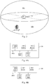
- the Fig. 2 schematically illustrates an example of a range area around the antenna system 11 of the control station 10.
- the range of area around the antenna system 11 can be seen schematically as a dome placed on a horizontal cylinder having the antenna system at its center. This range includes 7 sectors.
- the six sectoral antennas 11A, 11B, 11C, 11D, 11E and 11F respectively define six sectors 21A, 21B, 21C, 21D, 21E and 21F.
- Each of the 6 sectors 21A, 21B, 21C, 21D, 21E and 21F has a semi-pyramidal form of azimuth "60 °" and "+ 8 °" elevation. All the pyramidal shapes share a single vertex located at the level of the antenna system 11.
- the sectors 21A, 21B, 21C, 21D, 21E and 21F form a combined sector of "360 °" azimuth and "+ 8 °" elevation written in the horizontal cylinder.
- the remaining part of the assembly formed by the dome and the cylinder is the sector 20 covered by the omnidirectional antenna 12.
- the drone 3A is located in the sector 21D covered by the antenna 11D and the drone 3B is located in the sector 20 covered by the antenna 12.
- Processor 1001 is capable of executing instructions loaded into RAM 1002 from ROM 1003, external memory (not shown), storage medium (such as an SD card), or a communication network. When the control module 10 is powered up, the processor 1001 is capable of reading instructions from RAM 1002 and executing them. In one embodiment, these instructions form a computer program causing the implementation of communications between the base station 10 and each drone of the drone system 1 and a procedure for selecting an antenna of the antenna system 11 to communicate with each drone in drone system 1 at a given time.
- the processing module 300 then comprises, connected by a communication bus 3000: a processor or CPU (“Central Processing Unit” in English) 3001; a random access memory RAM (“Random Access Memory” in English) 3002; a read only memory (ROM) 3003; a storage unit such as a hard disk or a storage medium reader, such as an SD (“Secure Digital”) card reader 3004; at least one communication interface 3005 allowing the processing module 300 to communicate with other modules or devices.
- the communication interface 3005 allows the processing module 300 to communicate with other modules such as an antenna switching module making it possible to select an antenna to be used at a given time or with the control station 10.
- the chosen modulation (ie the GMSK modulation) makes it possible to carry out a convolutional type channel coding due to a memory effect introduced by the Gaussian filter.
- the GMSK modulation is particularly suitable for achieving the desired bit rates on each channel provided in the frequency band used (ie the military frequency band [4.4 GHz; 4.9 GHz] or the civil band [5.031 GHz; 5.091 GHz]).
- the LDPC 6031 coding module can be followed by a row / column type time interleaving module.
- the interleaving is done on the useful data included in each time sub-interval of a time interval (timeslot).
- the Fig. 7 schematically illustrates a reception module.
- the communication interface 1005 of the control station 10 and the communication interface 3005 of each drone 3A and 3B each comprise a reception module identical to the reception module described in relation to the Fig. 7 .
- the LDPC 6031 coding module is followed by a time / line type column / interleaving module
- the LDPC 7092 decoding module is preceded by a time deinterlacing module by row / column type.
- the transmission module comprises a transmission security module (TRANSEC)
- the reception module comprises a reciprocal transmission security module.
- the TDMA divides time into a first level of hierarchy called epoch (EPOCH in English terminology) (not shown in the Fig. 5 ) for example with a duration of "1s".
- EPOCH a first level of hierarchy
- An advantage of using an epoch with a duration of "1 s" is, in the case of using a universal time reference delivered for example by a GPS signal ("Global Positioning System" in English terminology), allow a passage from one communication cell to another synchronously.
- the communication system of the drone system 1 therefore makes it possible to comply with a second main constraint.
- an epoch is divided into “5” frames, for example with a duration of “200 ms”.
- a frame duration of “200 ms” provides latency in communication between a drone and the control station compatible with the transmission of audio conversation data.
- the communication system of the drone system 1 respects a third main constraint.
- a group of frames 50 is shown in Fig. 5 .
- the group of frames 50 comprises a number of frames equal to the number of antennas of the antenna system 11 of the control station ( ie . Seven) multiplied by the number of drones active in the drone system 1 ( ie two drones). There are therefore as many frames in a group of frames as possible couples formed by an antenna of the antenna system 11 and a drone.
- the group of frames 50 therefore comprises fourteen frames 501 to 514.
- a frame 414 belongs to a group of fourteen frames preceding the group of frames 50 and a frame 601 belongs to a group of fourteen frames following the group of frames 50.
- We will see by following that the organization into groups of frames makes it possible to define in the drone system 1 which antenna of the antenna system 11 must emit a signal towards a given drone and thus to implement an antenna selection procedure offering the best quality of transmission between the control station 10 and said drone.
- the plurality of time intervals further comprises a second interval 500B allowing the drone designated by the first signal to emit a second signal thereby enabling it to acknowledge its presence in the drone system 1.
- the Fig. 5 further gives a detail of an interval (timeslot) of the frame 502, each interval of a frame having an identical structure.
- An interval of a frame includes a 5000A subinterval making it possible to take into account propagation times in the drone system 1, and a set of 5000B subintervals (called “burst interval” in English terminology).
- the propagation time to reach one of the drones 3A or 3B from the control station 10 at a typical maximum distance of “200 km” for radio signals used in the military frequency band [4.4 GHz; 4.9 GHz] or the civil band [5.031 GHz; 5.091 GHz] is around "0.8 ms".
- each interval includes a set of "5" 5000B subintervals.
- the allocation table describes the structure in intervals of the intervals (timeslot).
- Table TAB 1 represents a table for allocating the intervals of a frame. This allocation table describes for each interval of a frame, identified by a interval number, the numbers of the sub-intervals included in this interval, an identifier of a transmitting node which can transmit during this interval, an identifier of a receiving node which can receive during this interval, an identifier of a coding ratio channel.
- the identifiers “000”, “001” and “010” are for example the identifiers of the control station 10, of the drone 3A and of the drone 3B respectively.
- the identifiers “00”, “01”, “10” and “11” are for example coding rate identifiers “0”, “1/3”, “1/2” and “2/3” respectively.
- LDPC 6031 coder When all the identifiers associated with a sub-interval are "0", each node of the network can deduce that this sub-interval is not allocated.
- each interval is associated with a frequency channel number identifier which can be used by the transmission security module.
- Each frequency channel identifier identifies one of the channels available in the military frequency band [4.4 GHz; 4.9 GHz] or the civil band [5.031 GHz; 5.091 GHz].
- Each data block (burst) transmitted during a sub-interval can thus be transmitted using a different frequency. Dividing an interval into “5” sub-intervals makes it possible to obtain “250” frequency hops per second.
- the data representative of the sub-interval number transmitted during the period 50000D are coded by the coding module BCH 6032 independently of all other data of the sub-interval.
- a period 50000E (called data block ) is used to transmit useful data.
- the useful data transmitted during the 50000E period is coded by the LDPC 6031 coding module.
- the independent encoding of the data corresponding to the sub-interval number makes it possible to decode this data without having to decode the useful data.
- a processing module (100 or 300) is able to determine whether useful data transmitted in a data block is intended for it or not, without having to decode said useful data.
- each group of frames used in the drone system 1 is organized according to a group structure associating each frame with a pair formed by an antenna of the control station 10 and a drone, each possible couple being associated with a different frame depending on the position of said frame in the group.
- the frames 501 to 507 are associated with the drone 3A and the frames 508 to 514 are associated with the drone 3B.
- the frame 501 is associated with the antenna 11A
- the frame 502 is associated with the antenna 11B
- the frame 503 is associated with the antenna 11C
- the frame 504 is associated with the antenna 11D
- the frame 505 is associated with the antenna 11E
- the frame 506 is associated with the antenna 11F
- the frame 507 is associated with the antenna 12.
- the frame 508 is associated with the antenna 11A
- the frame 509 is associated with the antenna 11B
- the frame 510 is associated with the antenna 11C
- the frame 511 is associated with the antenna 11D
- the frame 512 is associated with the antenna 11E
- the frame 513 is associated with the antenna 11F
- the frame 514 is associated on the air 12.
- the processing module 100 receives an acknowledgment signal from the drone 3A containing information representative of a quality of reception of the beacon measured by the drone.
- Information representative of a quality of reception is for example a measurement of RSSI (“Received Signal Strength Indication” in English terminology) measured during reception of a beacon.
- the processing module 100 determines which antenna offers the best quality of communication and selects this antenna for a predetermined number of frames according to the frame 507. For example, the processing module 100 selects an antenna for the 3A drone until the transmission of the next frame containing a beacon designating the 3A drone. In the example of the Fig. 1 with two drones in drone system 1, this amounts to selecting an antenna for “7” frames.
- the processing module 100 does the same for the drone 3B from frames 508 to 514 to select the best antenna to communicate with the drone 3B.
Landscapes
- Engineering & Computer Science (AREA)
- Signal Processing (AREA)
- Computer Networks & Wireless Communication (AREA)
- Mobile Radio Communication Systems (AREA)
- Aviation & Aerospace Engineering (AREA)
Claims (8)
- Kommunikationssystem, welches in einem System von unbemannten mobilen Vorrichtungen (1) enthalten ist, das eine Steuerstation (10) und wenigstens eine unbemannte mobile Vorrichtung (3A, 3B) umfasst, und welches jeder unbemannten mobilen Vorrichtung ermöglicht, mit der Steuerstation (10) unter Anwendung eines Zugriffsverfahrens auf das Medium vom Typ eines Mehrfachzugriffs durch Zeitmultiplex zu kommunizieren, bei welchem jede Kommunikation in Rahmen erfolgt, wobei eine Rahmendauer für jeden in dem Kommunikationssystem verwendeten Rahmen so definiert ist, dass Latenzzeiten in jeder Kommunikation zwischen jeder unbemannten mobilen Vorrichtung (3A, 3B) und der Basisstation (10) erhalten werden, die mit einer Übertragung von Gesprächsaudiodaten kompatibel sind;
wobei das System dadurch gekennzeichnet ist, dass jeder Rahmen in mehrere Zeitschlitze aufgeteilt ist, die einen ersten Zeitschlitz (500A) umfassen, welcher der Steuerstation (10) ermöglicht, ein erstes Signal zu senden, das eine unbemannte mobile Vorrichtung (3A, 3B) bezeichnet, und jeder unbemannten mobilen Vorrichtung (3A, 3B) ermöglicht, sich mit einer von der Steuerstation (10) gelieferten Zeitreferenz zu synchronisieren, einen zweite Zeitschlitz (500B), welcher der durch das erste Signal bezeichneten unbemannten mobilen Vorrichtung (3A, 3B) ermöglicht, ein zweites Signal zu senden, das ihr somit ermöglicht, ihre Anwesenheit in dem System von unbemannten mobilen Vorrichtungen (1) zu bestätigen, und eine Folge von Zeitschlitzen (500C), die eine Anzahl von Zeitschlitzen umfasst, welche von einer maximalen Anzahl unbemannter mobiler Vorrichtungen abhängt, die von der Steuerstation (10) in dem System von unbemannten mobilen Vorrichtungen (1) gesteuert werden kann, wobei die Zeitschlitze der Folge von Zeitschlitzen (500C) verwendet werden, um Nutzdaten zwischen jeder unbemannten mobilen Vorrichtung (3A, 3B) und der Steuerstation (10) auszutauschen; und
jeder Zeitschlitz in mehrere Teilzeitschlitze (5000A, 5000B) mit einer Dauer aufgeteilt ist, die es ermöglicht, während dieser Dauer einen stationären Kanal zu erhalten. - Kommunikationssystem nach Anspruch 1, dadurch gekennzeichnet, dass die Steuerstation (10) eine Vielzahl von Sektorantennen (11) umfasst, die jeweils einen vordefinierten Sektor in der Umgebung dieser Vielzahl abdecken, und dadurch, dass die in dem System verwendeten Rahmen in einer Folge von Gruppen von aufeinander folgenden Rahmen (50) organisiert sind, wobei jede Gruppe von Rahmen gemäß einer Gruppenstruktur organisiert ist, die jedem Rahmen ein Paar zuordnet, das von einer Antenne der Steuerstation (10) und einer unbemannten mobilen Vorrichtung (3A, 3B), die in dem System von unbemannten mobilen Vorrichtungen (1) enthalten ist, gebildet wird, wobei jedes mögliche Paar einem anderen Rahmen der Gruppe von Rahmen (50) in Abhängigkeit von einer Position des Rahmens in der Gruppe zugeordnet ist, wobei eine Information, die für die Struktur der Gruppe repräsentativ ist, zwischen der Steuerstation (10) und jeder unbemannten mobilen Vorrichtung (3A, 3B) geteilt wird.
- Kommunikationssystem nach Anspruch 2, dadurch gekennzeichnet, dass für jeden Rahmen eine Information, die für Merkmale der in dem Rahmen enthaltenen Zeitschlitze repräsentativ ist, von der Steuerstation (10) und jeder unbemannten mobilen Vorrichtung (3A, 3B) geteilt wird, wobei diese Information für jeden Zeitschlitz eine Information, die für in dem Zeitschlitz enthaltene Teilzeitschlitz-Nummern repräsentativ ist, eine Kennung einer Vorrichtung, welche die Steuerstation (10) oder eine der unbemannten mobilen Vorrichtungen (3A, 3B) ist, die während des Zeitschlitzes Nutzdaten senden kann, und eine Kennung einer Vorrichtung, welche die Steuerstation (10) oder eine der unbemannten mobilen Vorrichtungen (3A, 3B) ist, die während des Zeitschlitzes Nutzdaten empfangen kann, umfasst.
- Kommunikationssystem nach Anspruch 3, dadurch gekennzeichnet, dass die Information, die für Merkmale der in dem Rahmen enthaltenen Zeitschlitze repräsentativ ist, außerdem für jeden Zeitschlitz eine Kennung eine Codierrate eines Fehlerkorrekturcodes umfasst, der auf die während des Zeitschlitzes übertragenen Nutzdaten angewendet wird.
- Kommunikationssystem nach einem der vorhergehenden Ansprüche, dadurch gekennzeichnet, dass jeder Teilzeitschlitz in mehrere Perioden aufgeteilt ist, die eine Periode (50000C) umfassen, die verwendet wird, um eine Symbolfolge zu übertragen, die der Steuerstation (10) oder der unbemannten mobilen Vorrichtung (3A, 3B), welche die Symbolfolge empfängt, ermöglicht, eine Kanalschätzung durchzuführen, um Frequenz-, Phasen-, Taktsynchronisierungen und Entzerrungen von Empfangssignalen durchzuführen, und/oder eine Periode (50000D), die es ermöglicht, Daten zu übertragen, die für eine Teilzeitschlitz-Nummer repräsentativ sind.
- Kommunikationssystem nach einem der vorhergehenden Ansprüche, dadurch gekennzeichnet, dass die Steuerstation (10) und jede unbemannte mobile Vorrichtung (3A, 3B) ein Sendemodul umfassen, welches umfasst:ein Kanalcodierungsmodul (603), das ein LDPC-Codierungsmodul (6031), das verwendet wird, um die während eines Zeitschlitzes übertragenen Nutzdaten zu codieren, und ein BCH-Codierungsmodul (6032), das verwendet wird, um die Daten zu codieren, die für eine Teilzeitschlitz-Nummer repräsentativ sind, umfasst;ein Basisband-Filterungsmodul (604) vom Typ eines Gauß-Filters; undein Modul (605) für Minimum Shift Keying Modulation; undein Empfangsmodul, welches umfasst:ein Basisband-Filterungsmodul (705), das dafür ausgelegt ist, eine Selektivität im Basisband sicherzustellen;ein Modul zur Demodulation (708) einer Minimum Shift Keying Modulation;ein BCH-Decodierungsmodul (7091); undein LDPC-Decodierungsmodul (7092).
- Kommunikationssystem nach Anspruch 6, dadurch gekennzeichnet, dass das Sendemodul außerdem ein Übertragungssicherheitsmodul umfasst, das ein Frequenzsprungverfahren anwendet, und das Empfangsmodul außerdem ein reziprokes Übertragungssicherheitsmodul umfasst, das dem Übertragungssicherheitsmodul entspricht; und
die Information, die für Merkmale der in dem Rahmen enthaltenen Zeitschlitze repräsentativ ist, außerdem für jeden Zeitschlitz eine Kennung einer Frequenzkanalnummer umfasst, die von dem Übertragungssicherheitsmodul verwendet wird. - Kommunikationssystem nach Anspruch 6 oder 7, dadurch gekennzeichnet, dass dem LDPC-Codierungsmodul (6031) ein Zeitverschachtelungsmodul vom Typ Zeile/Spalte nachfolgt und dem LDPC-Decodierungsmodul (7092) ein Zeitentschachtelungsmodul vom Typ Zeile/Spalte vorausgeht.
Applications Claiming Priority (2)
| Application Number | Priority Date | Filing Date | Title |
|---|---|---|---|
| FR1601400A FR3056874B1 (fr) | 2016-09-26 | 2016-09-26 | Systeme de communication dans un systeme de drone |
| PCT/EP2017/074238 WO2018055164A1 (fr) | 2016-09-26 | 2017-09-25 | Systeme de communication dans un systeme de drones |
Publications (2)
| Publication Number | Publication Date |
|---|---|
| EP3516793A1 EP3516793A1 (de) | 2019-07-31 |
| EP3516793B1 true EP3516793B1 (de) | 2020-05-27 |
Family
ID=58054166
Family Applications (1)
| Application Number | Title | Priority Date | Filing Date |
|---|---|---|---|
| EP17772064.6A Active EP3516793B1 (de) | 2016-09-26 | 2017-09-25 | System zur kommunikation in einem system aus drohnen |
Country Status (6)
| Country | Link |
|---|---|
| US (1) | US10469160B2 (de) |
| EP (1) | EP3516793B1 (de) |
| CN (1) | CN110192357B (de) |
| FR (1) | FR3056874B1 (de) |
| IL (1) | IL265317B (de) |
| WO (1) | WO2018055164A1 (de) |
Families Citing this family (2)
| Publication number | Priority date | Publication date | Assignee | Title |
|---|---|---|---|---|
| WO2021035639A1 (zh) * | 2019-08-29 | 2021-03-04 | 深圳市大疆创新科技有限公司 | 一种遥控信号的处理方法、遥控设备及遥控系统 |
| US10797920B1 (en) * | 2020-03-18 | 2020-10-06 | Rockwell Collins, Inc. | High-entropy continuous phase modulation data transmitter |
Family Cites Families (13)
| Publication number | Priority date | Publication date | Assignee | Title |
|---|---|---|---|---|
| US6631124B1 (en) * | 1999-11-03 | 2003-10-07 | Ericsson Inc. | Methods and apparatus for allocating resources in hybrid TDMA communication systems |
| US8184572B1 (en) * | 2007-12-19 | 2012-05-22 | Rockwell Collins, Inc. | Real time control and management of a TDMA radio |
| CN101651992B (zh) * | 2009-09-18 | 2011-01-05 | 北京航空航天大学 | 一种用于无人飞行器自主编队的数据链组网方法 |
| US8942197B2 (en) * | 2011-10-24 | 2015-01-27 | Harris Corporation | Mobile ad hoc network with dynamic TDMA slot assignments and related methods |
| CN102778235B (zh) * | 2012-06-28 | 2015-01-28 | 西北工业大学 | 通信约束下的多无人机协同区域搜索方法 |
| US9527587B2 (en) * | 2012-12-19 | 2016-12-27 | Elwha Llc | Unoccupied flying vehicle (UFV) coordination |
| CN103490842B (zh) * | 2013-09-26 | 2016-09-28 | 深圳市大疆创新科技有限公司 | 数据传输系统及方法 |
| US9859972B2 (en) * | 2014-02-17 | 2018-01-02 | Ubiqomm Llc | Broadband access to mobile platforms using drone/UAV background |
| FR3043917A1 (fr) * | 2015-11-19 | 2017-05-26 | Chouette | Drone a stockage electrique reparti |
| EP3445651A1 (de) * | 2016-04-22 | 2019-02-27 | Gozluklu, Burak | Dreidimensionales skalierbares und modulares flugzeug |
| US20180244386A1 (en) * | 2017-02-13 | 2018-08-30 | Top Flight Technologies, Inc. | Weather sensing |
| US10127822B2 (en) * | 2017-02-13 | 2018-11-13 | Qualcomm Incorporated | Drone user equipment indication |
| US20190100108A1 (en) * | 2017-09-29 | 2019-04-04 | Qualcomm Incorporated | Robotic Vehicle Renewable Resource Charging Station Management Systems and Methods |
-
2016
- 2016-09-26 FR FR1601400A patent/FR3056874B1/fr not_active Expired - Fee Related
-
2017
- 2017-09-25 US US16/331,838 patent/US10469160B2/en active Active
- 2017-09-25 CN CN201780058919.8A patent/CN110192357B/zh active Active
- 2017-09-25 WO PCT/EP2017/074238 patent/WO2018055164A1/fr not_active Ceased
- 2017-09-25 EP EP17772064.6A patent/EP3516793B1/de active Active
-
2019
- 2019-03-12 IL IL265317A patent/IL265317B/en not_active IP Right Cessation
Non-Patent Citations (1)
| Title |
|---|
| None * |
Also Published As
| Publication number | Publication date |
|---|---|
| CN110192357B (zh) | 2022-02-15 |
| US20190253138A1 (en) | 2019-08-15 |
| US10469160B2 (en) | 2019-11-05 |
| EP3516793A1 (de) | 2019-07-31 |
| IL265317A (en) | 2019-05-30 |
| IL265317B (en) | 2020-03-31 |
| WO2018055164A1 (fr) | 2018-03-29 |
| CN110192357A (zh) | 2019-08-30 |
| FR3056874A1 (fr) | 2018-03-30 |
| FR3056874B1 (fr) | 2018-12-07 |
Similar Documents
| Publication | Publication Date | Title |
|---|---|---|
| EP3607673A1 (de) | Raumkommunikationsverfahren für iot-dienste und entsprechendes raumtelekommunikationssystem | |
| US8588086B2 (en) | Reverse link data rate indication for satellite-enabled communications systems | |
| Wang et al. | On the performance of non-terrestrial networks to support the internet of things | |
| EP3516793B1 (de) | System zur kommunikation in einem system aus drohnen | |
| CA2769537C (fr) | Methode d'acces multiple aux ressources radio dans un reseau ad hoc mobile et systeme mettant en oeuvre la methode | |
| EP4561225A1 (de) | Slprs- und slprs-cch-multplex-verfahren und vorrichtung zur sl-positionierung | |
| EP0616445B1 (de) | Duplexmehrträgerbinäre Funkübertragungsanordnung, entsprechende Mobile- und Feststation | |
| EP0977380A1 (de) | Zellulares Funkkommunikationssystem unter verwendung von Datenwiederholung in Abwärtsrichtung von einer Basistation und Datenrelais dafür | |
| EP3516794B1 (de) | Verfahren zur unterscheidung von uplink- oder downlink-kommunikation | |
| WO2016139202A1 (fr) | Procede et systeme de transmission multi-utilisateur 4d-tdma | |
| EP3910818A1 (de) | Verfahren zur sammlung von daten durch einen satelliten | |
| WO2018055179A1 (fr) | Procede de selection d'une antenne | |
| WO2003107562A2 (en) | Burst communications system and method | |
| WO2009053402A1 (fr) | Dispositif et procede permettant d'intercepter des communications dans un reseau | |
| EP2050208A1 (de) | Zeitabhängiges verfahren zum synchronisieren eines funkkommunikationssystems | |
| EP2689541B1 (de) | Tdma-kommunikationsvorrichtung mit zwei antennen zur übertragung von zwei baken | |
| EP3888402A1 (de) | Verfahren zur vorwegnahme von übertragungsressourcen für echtzeit-datenrouting | |
| Wong et al. | Detection probabilities for satellite VHF data exchange system with decollision algorithm and spot beam | |
| EP2329612B1 (de) | Verfahren zum zugreifen auf eine übertragung ohne einen fequenzduplexer | |
| EP3732800B1 (de) | Verfahren und system zum einfügen eines terminals in ein satellitennetzwerk | |
| EP3506527B1 (de) | Steuerungsverfahren eines kommunikationsnetzes, und entsprechendes kommunikationsnetz | |
| EP4687309A1 (de) | Verfahren zum richten eines satcom-endgeräts zu einem satelliten eines nicht-begrabenen zellularen kommunikationsnetzes | |
| WO2008009401A1 (fr) | Système de téléphonie cellulaire dans lequel un terminal esclave est adapté à émettre des données à destination d'un terminal maître selon un canal de trafic de type simplex montant | |
| WO2021123132A1 (fr) | Procede, dispositif et systeme de selection d'une antenne | |
| Johnson et al. | Feasibility Study of R-Mode using AIS Transmissions |
Legal Events
| Date | Code | Title | Description |
|---|---|---|---|
| STAA | Information on the status of an ep patent application or granted ep patent |
Free format text: STATUS: UNKNOWN |
|
| STAA | Information on the status of an ep patent application or granted ep patent |
Free format text: STATUS: THE INTERNATIONAL PUBLICATION HAS BEEN MADE |
|
| PUAI | Public reference made under article 153(3) epc to a published international application that has entered the european phase |
Free format text: ORIGINAL CODE: 0009012 |
|
| STAA | Information on the status of an ep patent application or granted ep patent |
Free format text: STATUS: REQUEST FOR EXAMINATION WAS MADE |
|
| 17P | Request for examination filed |
Effective date: 20190423 |
|
| AK | Designated contracting states |
Kind code of ref document: A1 Designated state(s): AL AT BE BG CH CY CZ DE DK EE ES FI FR GB GR HR HU IE IS IT LI LT LU LV MC MK MT NL NO PL PT RO RS SE SI SK SM TR |
|
| AX | Request for extension of the european patent |
Extension state: BA ME |
|
| DAV | Request for validation of the european patent (deleted) | ||
| DAX | Request for extension of the european patent (deleted) | ||
| REG | Reference to a national code |
Ref country code: DE Ref legal event code: R079 Ref document number: 602017017420 Country of ref document: DE Free format text: PREVIOUS MAIN CLASS: H04B0007260000 Ipc: H04L0005140000 |
|
| GRAP | Despatch of communication of intention to grant a patent |
Free format text: ORIGINAL CODE: EPIDOSNIGR1 |
|
| STAA | Information on the status of an ep patent application or granted ep patent |
Free format text: STATUS: GRANT OF PATENT IS INTENDED |
|
| RIC1 | Information provided on ipc code assigned before grant |
Ipc: B64C 39/02 20060101ALI20200117BHEP Ipc: H04L 5/00 20060101ALI20200117BHEP Ipc: H04L 5/14 20060101AFI20200117BHEP Ipc: H04B 7/26 20060101ALI20200117BHEP |
|
| INTG | Intention to grant announced |
Effective date: 20200225 |
|
| GRAS | Grant fee paid |
Free format text: ORIGINAL CODE: EPIDOSNIGR3 |
|
| GRAA | (expected) grant |
Free format text: ORIGINAL CODE: 0009210 |
|
| STAA | Information on the status of an ep patent application or granted ep patent |
Free format text: STATUS: THE PATENT HAS BEEN GRANTED |
|
| AK | Designated contracting states |
Kind code of ref document: B1 Designated state(s): AL AT BE BG CH CY CZ DE DK EE ES FI FR GB GR HR HU IE IS IT LI LT LU LV MC MK MT NL NO PL PT RO RS SE SI SK SM TR |
|
| REG | Reference to a national code |
Ref country code: GB Ref legal event code: FG4D Free format text: NOT ENGLISH |
|
| REG | Reference to a national code |
Ref country code: CH Ref legal event code: EP |
|
| REG | Reference to a national code |
Ref country code: AT Ref legal event code: REF Ref document number: 1275695 Country of ref document: AT Kind code of ref document: T Effective date: 20200615 |
|
| REG | Reference to a national code |
Ref country code: DE Ref legal event code: R096 Ref document number: 602017017420 Country of ref document: DE |
|
| REG | Reference to a national code |
Ref country code: LT Ref legal event code: MG4D |
|
| PG25 | Lapsed in a contracting state [announced via postgrant information from national office to epo] |
Ref country code: PT Free format text: LAPSE BECAUSE OF FAILURE TO SUBMIT A TRANSLATION OF THE DESCRIPTION OR TO PAY THE FEE WITHIN THE PRESCRIBED TIME-LIMIT Effective date: 20200928 Ref country code: IS Free format text: LAPSE BECAUSE OF FAILURE TO SUBMIT A TRANSLATION OF THE DESCRIPTION OR TO PAY THE FEE WITHIN THE PRESCRIBED TIME-LIMIT Effective date: 20200927 Ref country code: SE Free format text: LAPSE BECAUSE OF FAILURE TO SUBMIT A TRANSLATION OF THE DESCRIPTION OR TO PAY THE FEE WITHIN THE PRESCRIBED TIME-LIMIT Effective date: 20200527 Ref country code: FI Free format text: LAPSE BECAUSE OF FAILURE TO SUBMIT A TRANSLATION OF THE DESCRIPTION OR TO PAY THE FEE WITHIN THE PRESCRIBED TIME-LIMIT Effective date: 20200527 Ref country code: GR Free format text: LAPSE BECAUSE OF FAILURE TO SUBMIT A TRANSLATION OF THE DESCRIPTION OR TO PAY THE FEE WITHIN THE PRESCRIBED TIME-LIMIT Effective date: 20200828 Ref country code: NO Free format text: LAPSE BECAUSE OF FAILURE TO SUBMIT A TRANSLATION OF THE DESCRIPTION OR TO PAY THE FEE WITHIN THE PRESCRIBED TIME-LIMIT Effective date: 20200827 Ref country code: LT Free format text: LAPSE BECAUSE OF FAILURE TO SUBMIT A TRANSLATION OF THE DESCRIPTION OR TO PAY THE FEE WITHIN THE PRESCRIBED TIME-LIMIT Effective date: 20200527 |
|
| REG | Reference to a national code |
Ref country code: NL Ref legal event code: MP Effective date: 20200527 |
|
| PG25 | Lapsed in a contracting state [announced via postgrant information from national office to epo] |
Ref country code: LV Free format text: LAPSE BECAUSE OF FAILURE TO SUBMIT A TRANSLATION OF THE DESCRIPTION OR TO PAY THE FEE WITHIN THE PRESCRIBED TIME-LIMIT Effective date: 20200527 Ref country code: BG Free format text: LAPSE BECAUSE OF FAILURE TO SUBMIT A TRANSLATION OF THE DESCRIPTION OR TO PAY THE FEE WITHIN THE PRESCRIBED TIME-LIMIT Effective date: 20200827 Ref country code: RS Free format text: LAPSE BECAUSE OF FAILURE TO SUBMIT A TRANSLATION OF THE DESCRIPTION OR TO PAY THE FEE WITHIN THE PRESCRIBED TIME-LIMIT Effective date: 20200527 Ref country code: HR Free format text: LAPSE BECAUSE OF FAILURE TO SUBMIT A TRANSLATION OF THE DESCRIPTION OR TO PAY THE FEE WITHIN THE PRESCRIBED TIME-LIMIT Effective date: 20200527 |
|
| REG | Reference to a national code |
Ref country code: AT Ref legal event code: MK05 Ref document number: 1275695 Country of ref document: AT Kind code of ref document: T Effective date: 20200527 |
|
| PG25 | Lapsed in a contracting state [announced via postgrant information from national office to epo] |
Ref country code: NL Free format text: LAPSE BECAUSE OF FAILURE TO SUBMIT A TRANSLATION OF THE DESCRIPTION OR TO PAY THE FEE WITHIN THE PRESCRIBED TIME-LIMIT Effective date: 20200527 Ref country code: AL Free format text: LAPSE BECAUSE OF FAILURE TO SUBMIT A TRANSLATION OF THE DESCRIPTION OR TO PAY THE FEE WITHIN THE PRESCRIBED TIME-LIMIT Effective date: 20200527 |
|
| PG25 | Lapsed in a contracting state [announced via postgrant information from national office to epo] |
Ref country code: SM Free format text: LAPSE BECAUSE OF FAILURE TO SUBMIT A TRANSLATION OF THE DESCRIPTION OR TO PAY THE FEE WITHIN THE PRESCRIBED TIME-LIMIT Effective date: 20200527 Ref country code: EE Free format text: LAPSE BECAUSE OF FAILURE TO SUBMIT A TRANSLATION OF THE DESCRIPTION OR TO PAY THE FEE WITHIN THE PRESCRIBED TIME-LIMIT Effective date: 20200527 Ref country code: AT Free format text: LAPSE BECAUSE OF FAILURE TO SUBMIT A TRANSLATION OF THE DESCRIPTION OR TO PAY THE FEE WITHIN THE PRESCRIBED TIME-LIMIT Effective date: 20200527 Ref country code: DK Free format text: LAPSE BECAUSE OF FAILURE TO SUBMIT A TRANSLATION OF THE DESCRIPTION OR TO PAY THE FEE WITHIN THE PRESCRIBED TIME-LIMIT Effective date: 20200527 Ref country code: IT Free format text: LAPSE BECAUSE OF FAILURE TO SUBMIT A TRANSLATION OF THE DESCRIPTION OR TO PAY THE FEE WITHIN THE PRESCRIBED TIME-LIMIT Effective date: 20200527 Ref country code: CZ Free format text: LAPSE BECAUSE OF FAILURE TO SUBMIT A TRANSLATION OF THE DESCRIPTION OR TO PAY THE FEE WITHIN THE PRESCRIBED TIME-LIMIT Effective date: 20200527 Ref country code: RO Free format text: LAPSE BECAUSE OF FAILURE TO SUBMIT A TRANSLATION OF THE DESCRIPTION OR TO PAY THE FEE WITHIN THE PRESCRIBED TIME-LIMIT Effective date: 20200527 Ref country code: ES Free format text: LAPSE BECAUSE OF FAILURE TO SUBMIT A TRANSLATION OF THE DESCRIPTION OR TO PAY THE FEE WITHIN THE PRESCRIBED TIME-LIMIT Effective date: 20200527 |
|
| PG25 | Lapsed in a contracting state [announced via postgrant information from national office to epo] |
Ref country code: SK Free format text: LAPSE BECAUSE OF FAILURE TO SUBMIT A TRANSLATION OF THE DESCRIPTION OR TO PAY THE FEE WITHIN THE PRESCRIBED TIME-LIMIT Effective date: 20200527 Ref country code: PL Free format text: LAPSE BECAUSE OF FAILURE TO SUBMIT A TRANSLATION OF THE DESCRIPTION OR TO PAY THE FEE WITHIN THE PRESCRIBED TIME-LIMIT Effective date: 20200527 |
|
| REG | Reference to a national code |
Ref country code: DE Ref legal event code: R097 Ref document number: 602017017420 Country of ref document: DE |
|
| PLBE | No opposition filed within time limit |
Free format text: ORIGINAL CODE: 0009261 |
|
| STAA | Information on the status of an ep patent application or granted ep patent |
Free format text: STATUS: NO OPPOSITION FILED WITHIN TIME LIMIT |
|
| REG | Reference to a national code |
Ref country code: CH Ref legal event code: PL |
|
| 26N | No opposition filed |
Effective date: 20210302 |
|
| REG | Reference to a national code |
Ref country code: BE Ref legal event code: MM Effective date: 20200930 |
|
| PG25 | Lapsed in a contracting state [announced via postgrant information from national office to epo] |
Ref country code: LU Free format text: LAPSE BECAUSE OF NON-PAYMENT OF DUE FEES Effective date: 20200925 |
|
| PG25 | Lapsed in a contracting state [announced via postgrant information from national office to epo] |
Ref country code: LI Free format text: LAPSE BECAUSE OF NON-PAYMENT OF DUE FEES Effective date: 20200930 Ref country code: IE Free format text: LAPSE BECAUSE OF NON-PAYMENT OF DUE FEES Effective date: 20200925 Ref country code: CH Free format text: LAPSE BECAUSE OF NON-PAYMENT OF DUE FEES Effective date: 20200930 Ref country code: BE Free format text: LAPSE BECAUSE OF NON-PAYMENT OF DUE FEES Effective date: 20200930 |
|
| PG25 | Lapsed in a contracting state [announced via postgrant information from national office to epo] |
Ref country code: TR Free format text: LAPSE BECAUSE OF FAILURE TO SUBMIT A TRANSLATION OF THE DESCRIPTION OR TO PAY THE FEE WITHIN THE PRESCRIBED TIME-LIMIT Effective date: 20200527 Ref country code: MT Free format text: LAPSE BECAUSE OF FAILURE TO SUBMIT A TRANSLATION OF THE DESCRIPTION OR TO PAY THE FEE WITHIN THE PRESCRIBED TIME-LIMIT Effective date: 20200527 Ref country code: CY Free format text: LAPSE BECAUSE OF FAILURE TO SUBMIT A TRANSLATION OF THE DESCRIPTION OR TO PAY THE FEE WITHIN THE PRESCRIBED TIME-LIMIT Effective date: 20200527 |
|
| PG25 | Lapsed in a contracting state [announced via postgrant information from national office to epo] |
Ref country code: MK Free format text: LAPSE BECAUSE OF FAILURE TO SUBMIT A TRANSLATION OF THE DESCRIPTION OR TO PAY THE FEE WITHIN THE PRESCRIBED TIME-LIMIT Effective date: 20200527 Ref country code: MC Free format text: LAPSE BECAUSE OF FAILURE TO SUBMIT A TRANSLATION OF THE DESCRIPTION OR TO PAY THE FEE WITHIN THE PRESCRIBED TIME-LIMIT Effective date: 20200527 |
|
| PG25 | Lapsed in a contracting state [announced via postgrant information from national office to epo] |
Ref country code: SI Free format text: LAPSE BECAUSE OF FAILURE TO SUBMIT A TRANSLATION OF THE DESCRIPTION OR TO PAY THE FEE WITHIN THE PRESCRIBED TIME-LIMIT Effective date: 20200527 |
|
| PGFP | Annual fee paid to national office [announced via postgrant information from national office to epo] |
Ref country code: DE Payment date: 20250919 Year of fee payment: 9 |
|
| PGFP | Annual fee paid to national office [announced via postgrant information from national office to epo] |
Ref country code: GB Payment date: 20250923 Year of fee payment: 9 |
|
| PGFP | Annual fee paid to national office [announced via postgrant information from national office to epo] |
Ref country code: FR Payment date: 20250917 Year of fee payment: 9 |