EP3516938A1 - Outil de traitement de sol - Google Patents
Outil de traitement de sol Download PDFInfo
- Publication number
- EP3516938A1 EP3516938A1 EP18153860.4A EP18153860A EP3516938A1 EP 3516938 A1 EP3516938 A1 EP 3516938A1 EP 18153860 A EP18153860 A EP 18153860A EP 3516938 A1 EP3516938 A1 EP 3516938A1
- Authority
- EP
- European Patent Office
- Prior art keywords
- cutting
- cutting elements
- base body
- soil cultivation
- cassettes
- Prior art date
- Legal status (The legal status is an assumption and is not a legal conclusion. Google has not performed a legal analysis and makes no representation as to the accuracy of the status listed.)
- Granted
Links
Images


Classifications
-
- A—HUMAN NECESSITIES
- A01—AGRICULTURE; FORESTRY; ANIMAL HUSBANDRY; HUNTING; TRAPPING; FISHING
- A01B—SOIL WORKING IN AGRICULTURE OR FORESTRY; PARTS, DETAILS, OR ACCESSORIES OF AGRICULTURAL MACHINES OR IMPLEMENTS, IN GENERAL
- A01B35/00—Other machines for working soil
- A01B35/20—Tools; Details
- A01B35/22—Non-rotating tools; Resilient or flexible mounting of rigid tools
- A01B35/26—Rigid tools
-
- A—HUMAN NECESSITIES
- A01—AGRICULTURE; FORESTRY; ANIMAL HUSBANDRY; HUNTING; TRAPPING; FISHING
- A01B—SOIL WORKING IN AGRICULTURE OR FORESTRY; PARTS, DETAILS, OR ACCESSORIES OF AGRICULTURAL MACHINES OR IMPLEMENTS, IN GENERAL
- A01B15/00—Elements, tools, or details of ploughs
- A01B15/02—Plough blades; Fixing the blades
-
- A—HUMAN NECESSITIES
- A01—AGRICULTURE; FORESTRY; ANIMAL HUSBANDRY; HUNTING; TRAPPING; FISHING
- A01B—SOIL WORKING IN AGRICULTURE OR FORESTRY; PARTS, DETAILS, OR ACCESSORIES OF AGRICULTURAL MACHINES OR IMPLEMENTS, IN GENERAL
- A01B15/00—Elements, tools, or details of ploughs
- A01B15/02—Plough blades; Fixing the blades
- A01B15/04—Shares
- A01B15/06—Interchangeable or adjustable shares
-
- A—HUMAN NECESSITIES
- A01—AGRICULTURE; FORESTRY; ANIMAL HUSBANDRY; HUNTING; TRAPPING; FISHING
- A01B—SOIL WORKING IN AGRICULTURE OR FORESTRY; PARTS, DETAILS, OR ACCESSORIES OF AGRICULTURAL MACHINES OR IMPLEMENTS, IN GENERAL
- A01B23/00—Elements, tools, or details of harrows
- A01B23/02—Teeth; Fixing the teeth
Definitions
- the invention relates to a tillage tool, in particular coulters, comprising a base body on which optionally cassettes are arranged, and at least first cutting elements, which are fixed to the base body or the cassettes for cutting in a soil along a working direction.
- Tillage tools such as goosefoot or other flocks have been indispensable in agriculture for some time for the treatment of soils or soil.
- Good soil preparation in advance of sowing is important to achieve a good harvest result. From an ecological point of view, due to the bad reputation of sprays and discussions about their use, it is also important today that good soil treatment can also effectively contribute to minimizing the required spray.
- Goosefoot coats are used in particular for shallow tillage.
- soil is usually cut at a depth of about 2 cm to 8 cm with one or more shares area, in particular weeds to be separated.
- the topmost layer of the soil is completely separated from the underlying soil, so that a treatment of the separated topmost layer is possible in an effective manner.
- goosefoot or appropriate tillage tools When cutting through the soil, goosefoot or appropriate tillage tools are pulled by a means of transport such as a tractor. The faces of the droves are then in cutting engagement with the soil. The so treated soil opposes the cutting acting crowd a lot of resistance, which is why the shares, which are usually made of steel, are subject to considerable wear.
- cemented carbide elements When cemented carbide elements are provided on tillage tools for a cutting engagement, they are brazed onto a base body. For this purpose, a groove is provided, in which the cutting plates are used, wherein the cutting plates touch.
- a groove is provided, in which the cutting plates are used, wherein the cutting plates touch.
- the object of the invention is to provide a tillage tool of the type mentioned, which can be produced in a simple manner and provides good work results in use.
- the first cutting elements are arranged in separate seats. It is advantageous that the at least first cutting elements can be easily positioned during soldering, wherein the positioning is in particular independent of other cutting elements. In addition, the first cutting elements in use can not influence each other mutually, for example, with a particularly high force on a single cutting element.
- first cutting elements which are usually formed as inserts
- second cutting elements and optionally further Be provided cutting elements are also provided. If further cutting elements are provided, it is preferred, however, for a cutting performance to be taken over completely or at least predominantly by the first cutting elements, which are arranged for this purpose in the corresponding seats.
- the seats have a stop for positioning the first cutting elements.
- the corresponding cutting elements can then be easily positioned in the individual seats during soldering.
- Another advantage results from the fact that when training the first cutting elements as cutting plates of the stop can be performed as before in the art around a cutting plate around, namely not only on a longitudinal side, but also partially a broad side of the first cutting elements or inserts , As a result, in the cutting insert, there is also a good distribution of force on the base body, which in turn contributes positively to the longevity of the tilling tool overall.
- first cutting elements are arranged at a distance from each other, mutual interference during a cutting insert is excluded, which brings about the explained advantages.
- the first cutting elements can be made of any material that provides sufficient mechanical properties in terms of strength, toughness and abrasive behavior.
- various composite materials or ceramics can be used.
- at least individual, preferably all, of the first cutting elements are formed from or with hard metal.
- the first cutting elements are inserts made of a carbide.
- the cemented carbide may be a cemented carbide having tungsten carbide in addition to a common binder metal of cobalt, iron and / or nickel in the amount of 6% (wt.) To 12% (wt.).
- the tungsten carbide may optionally be partially replaced by up to 25% by weight of titanium carbide.
- Average grain sizes of the tungsten carbide and of the optionally provided titanium carbide are in the range from 0.8 ⁇ m to 10 ⁇ m. Preference is given to average particle sizes of 1.5 ⁇ m to 4.0 ⁇ m.
- the first cutting elements in general and the cutting plates in particular may be coated, resulting in increased wear resistance.
- Preferred coatings are coatings of an aluminum oxide or an aluminum titanium nitride. Also possible are combined coatings with a large number of individual coating layers.
- the coating layers may in particular be deposited by means of a CVD method.
- a thickness of a possible coating layer is generally 2 ⁇ m to 15 ⁇ m, in particular 3 ⁇ m to 5 ⁇ m.
- the main body may be formed of a steel in a tillage tool according to the invention. If cassettes are provided, they are attached to the base body and carry the first cutting elements. Cassettes are particularly useful when the body does not wear on itself, but only the cutting active areas that are to be exchanged when a certain wear mark. On the cassettes then the first cutting elements are attached. The individual cassettes can be exchanged as needed. If cassettes are provided, they are advantageously made, just like the base body, of a steel. It can be the same steel as used for the body, but this is not mandatory.
- the main body can basically have any shape.
- the base body is formed substantially v-shaped in plan view.
- the individual first cutting elements are then fastened to the outside of the front side of the v-shape and form adjoining cutting regions.
- at least a second cutting element may be attached to the tip of the v-shape. It is expedient, however, that the first cutting elements are offset in a plan view of the base body along a working edge at least partially recessed to each other.
- the v-shape is then in use symmetrical to a working direction, wherein the cutting elements or cutting plates are arranged in plan view of the working edge with a predetermined inclination to the working edge. Due to the offset of the individual cutting elements to one another, it results that the frontal cutting edges of the individual cutting elements seen in the working direction partially overlap in relation to the cutting plane, so areas of the cutting edges are arranged in the working direction one behind the other. This has two advantages: On the one hand, this ensures that despite fastening the first cutting elements in individual, separate seats due to the mental overlap of the cutting edges of the gap between them is bridged. Thus, a planar separation of the soil can be achieved, although the first cutting elements are spaced apart.
- the overlapping of the cutting edges causes that portion of the cutting edge of a recessed first cutting element to become cutting active if the corresponding upstream region of the cutting edge of the adjacent, offset first cutting element is no longer cutting active.
- a service life of the tillage tool can be increased.
- weeds which are to be cut can not be easily dodged by sliding along a continuous cutting line, but cut more effectively.
- the individual first cutting elements can be made oblique with respect to a working edge.
- the extent of skew and return offset depends on the v-shape of the soil tillage implement.
- the arrangement of the first cutting elements with respect to inclination and return offset is chosen so that the above effects of the consecutive engagement of portions of individual cutting edges of adjacent cutting elements are achieved.
- An arrangement of the cutting elements, in particular when forming the same as inserts, is advantageously carried out so that viewed from the working direction individual cutting edges of the first cutting elements are arranged at the same height. This achieves the desired continuous, effective and areal cut in the soil.
- the cutting edges are partially arranged one behind the other as already explained in the working direction.
- the first cutting elements may in this context be positioned at an angle of 20 ° to 50 °, preferably 25 ° to 35 °, to a base surface of the base body. Appropriate angles are appropriate to achieve the desired cutting performance by a favorable wedge angle, while minimizing wear.
- the provided for the first cutting elements seats can be created in the body in any way, for example by laser cutting. It is also possible to already form a base body with appropriate shape. It is particularly favorable, however, if the base body is formed as a forging body made of steel and the seats are machined by machining, especially by milling. This allows a rapid and efficient production of a tillage tool, since after milling directly the hard metal assembly or attachment of cutting elements can be done by cohesive connection such as gluing or soldering.
- additional supplements are made to the base body to make this wear-resistant.
- These may in particular be complementary platelets which are fastened in suitable recesses on the base body and have a higher abrasive resistance to the sliding soil than the base body as such.
- platelets made of composite materials or a ceramic, but also tungsten carbide platelets are suitable for this purpose.
- these supplementary platelets are a wear protection for the body and do not develop a cutting action.
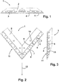
- Fig. 1 is a first example of a tillage tool according to the invention 1 shown in a front view.
- Fig. 2 is the same tillage tool 1 in plan view and in Fig. 3 shown in a side view.
- the tillage tool according to Fig. 1 to Fig. 3 has a base body 2.
- the main body 2 is formed from two substantially elongated side wings, which are chamfered on one side and connected to each other on this bevelled side.
- the main body 2 may consist of even more items, but may also be integrally formed.
- the main body 2 consists of a steel.
- the main body 2 has a v-shape in plan view, as in particular from Fig. 2 is apparent.
- On a front side of the V-shaped base body 2 a plurality of cassettes 3 is arranged.
- the cassettes 3 are detachably connected to the main body 2, for example by screws.
- the cassettes 3 cover an end face of the main body 2 or a working edge 11 entirely.
- the cassettes 3 may be made of a steel as the base body 2.
- the cassettes 3 may be formed of the same steel as the main body 2, which is not mandatory.
- first cutting elements 4 are mounted, which are formed as inserts.
- the inserts are located on an end face of the cassettes 3.
- Each cassette 3 except for the first end receives three inserts, although a different number of inserts may be provided on the cassettes 3.
- the inserts are made here of a higher-strength steel, a ceramic, such as silicon carbide, a composite material such as a particle-reinforced metal or more preferably a hard metal consist.
- each seat 9 is provided for the individual inserts.
- the seats each have a stop 10, so that the inserts can be particularly easily positioned when mounting in the cassette 3.
- the stops 10 also serve an efficient power dissipation from the inserts in the cassettes 3 when using the tillage tool. 1
- the individual inserts are spaced from each other due to the stops 10 and separated. Nevertheless, in order to achieve a continuous cutting line along a working edge 11, the individual cutting plates are set back relative to each other starting from the tip of the V-shaped soil working tool 1, so that each cutting plate each with a front corner 7 of a cutting edge in the region of a rear corner 8 of the previous cutting to come to rest. Due to the V-shaped design of the tillage tool.
- the individual inserts are connected in training of a hard metal to the cassettes 3 by soldering or gluing. If cutting edges 6 or inserts are close to a cassette 3 so far that they are no longer suitable for use, a single cassette can be solved. This results in the advantage that only an area-wise change in that area is required, which is just worn out. A use of cassettes 3 and inserts is thus minimized.
- a second example of a tillage tool 1 according to the invention is shown.
- the base body 2 is basically made in one piece and can be created for example by forging from a steel.
- the base body 2 has at least one opening, so that the base body 2 can be attached to the end of a towing vehicle such as a tractor and the tillage tool 1 can be pulled in the working direction 12. This corresponds to that mode of operation which also applies to a tillage tool 1 according to FIG Fig. 1 to Fig. 3 Application finds.
- the first cutting elements 4 are again formed as cutting plates, which are substantially rectangular in plan view as in the first example.
- the inserts can in turn be made with advantage of a hard metal and are in this case mounted directly on the base 2 by cohesive connection such as soldering or gluing.
- the inserts are again relative to each other along the working edge 11, according to Fig. 6 starting from a tip of the turn V-shaped body 2, starting to the rear, in each case to each other set back, so that in the case of the provided on the base body 2 9 seats even at the given in this example spacing of the individual inserts results in a continuous cut line.
- a spacing of the individual first cutting elements 4 or inserts in the individual seats 9 with stops 10 is in particular in the side view according to Fig. 7 seen.
- the first cutting elements 4 and inserts are mounted inclined and include approximately an angle of 30 ° with an imaginary base 13 of the body 2 a.
- Fig. 8 the main body 2 is shown without inserts, so that the individual seats 9 together with stops 10 are shown in detail.
- the individual, separate seats 9 for each individual cutting plate a simple positioning in the manufacture of the tillage tool 1 is achieved.
- Each individual cutting plate can be easily aligned separately on a stop 10 in a seat 9 and fixed there, in particular by soldering. Since the individual cutting plates along the working edge 11 are in turn set back relative to each other, results in spite of the arranged with the seats 9 spacing of individual inserts a continuous cutting line.
- At least a second cutting element 5 may be provided on the base body 2.
- the at least second cutting element 5 may be specially designed to cover, as can be seen, the tip of the v-shape of the base body 2 and, moreover, to provide the cutting power required even at the tip.
Landscapes
- Life Sciences & Earth Sciences (AREA)
- Engineering & Computer Science (AREA)
- Mechanical Engineering (AREA)
- Soil Sciences (AREA)
- Environmental Sciences (AREA)
- Soil Working Implements (AREA)
- Cultivation Receptacles Or Flower-Pots, Or Pots For Seedlings (AREA)
- Agricultural Machines (AREA)
Priority Applications (8)
| Application Number | Priority Date | Filing Date | Title |
|---|---|---|---|
| DK18153860.4T DK3516938T3 (da) | 2018-01-29 | 2018-01-29 | Jordbearbejdningsværktøj |
| LTEP18153860.4T LT3516938T (lt) | 2018-01-29 | 2018-01-29 | Dirvos dirbimo padargas |
| EP18153860.4A EP3516938B1 (fr) | 2018-01-29 | 2018-01-29 | Outil de traitement de sol |
| ES18153860T ES2919329T3 (es) | 2018-01-29 | 2018-01-29 | Herramienta de labranza de suelo |
| PL18153860T PL3516938T3 (pl) | 2018-01-29 | 2018-01-29 | Narzędzie do uprawy roli |
| SI201830660T SI3516938T1 (sl) | 2018-01-29 | 2018-01-29 | Orodje za obdelavo tal |
| CA3072015A CA3072015A1 (fr) | 2018-01-29 | 2019-01-29 | Outil de travail du sol |
| PCT/EP2019/052109 WO2019145558A1 (fr) | 2018-01-29 | 2019-01-29 | Outil de travail du sol |
Applications Claiming Priority (1)
| Application Number | Priority Date | Filing Date | Title |
|---|---|---|---|
| EP18153860.4A EP3516938B1 (fr) | 2018-01-29 | 2018-01-29 | Outil de traitement de sol |
Publications (2)
| Publication Number | Publication Date |
|---|---|
| EP3516938A1 true EP3516938A1 (fr) | 2019-07-31 |
| EP3516938B1 EP3516938B1 (fr) | 2022-03-23 |
Family
ID=61074387
Family Applications (1)
| Application Number | Title | Priority Date | Filing Date |
|---|---|---|---|
| EP18153860.4A Active EP3516938B1 (fr) | 2018-01-29 | 2018-01-29 | Outil de traitement de sol |
Country Status (8)
| Country | Link |
|---|---|
| EP (1) | EP3516938B1 (fr) |
| CA (1) | CA3072015A1 (fr) |
| DK (1) | DK3516938T3 (fr) |
| ES (1) | ES2919329T3 (fr) |
| LT (1) | LT3516938T (fr) |
| PL (1) | PL3516938T3 (fr) |
| SI (1) | SI3516938T1 (fr) |
| WO (1) | WO2019145558A1 (fr) |
Cited By (3)
| Publication number | Priority date | Publication date | Assignee | Title |
|---|---|---|---|---|
| EP3753383A1 (fr) * | 2019-06-19 | 2020-12-23 | BOEHLERIT GmbH & Co.KG. | Élément de coupe |
| EP3837934A1 (fr) * | 2019-12-19 | 2021-06-23 | BOEHLERIT GmbH & Co.KG. | Dispositif de traitement du sol destiné au traitement agricole de la terre |
| AT528025B1 (de) * | 2024-07-05 | 2025-09-15 | Boehlerit Gmbh & Co Kg | Leichtgewichtige Gänsefußschar |
Citations (7)
| Publication number | Priority date | Publication date | Assignee | Title |
|---|---|---|---|---|
| US991810A (en) * | 1911-01-10 | 1911-05-09 | Junius F Whiting | Plow. |
| US2316097A (en) * | 1940-08-22 | 1943-04-06 | Raymond V Pilliod | Plowshare |
| DE1222304B (de) * | 1965-06-11 | 1966-08-04 | Wilh Buchmuehlen O H G Landmas | Pflugschar |
| DE102013102420A1 (de) * | 2013-03-11 | 2014-09-11 | Betek Gmbh & Co. Kg | Scharspitze bzw. Werkzeugkombination mit einer Scharspitze |
| DE202009019047U1 (de) * | 2009-06-23 | 2015-11-30 | Betek Gmbh & Co. Kg | Bodenbearbeitungswerkzeug |
| EP2962538A1 (fr) * | 2010-07-15 | 2016-01-06 | Betek GmbH & Co. KG | Outil de travail du sol |
| EP2995180A2 (fr) | 2014-08-07 | 2016-03-16 | BOEHLERIT GmbH & Co.KG. | Outil de traitement de sol |
-
2018
- 2018-01-29 EP EP18153860.4A patent/EP3516938B1/fr active Active
- 2018-01-29 SI SI201830660T patent/SI3516938T1/sl unknown
- 2018-01-29 PL PL18153860T patent/PL3516938T3/pl unknown
- 2018-01-29 LT LTEP18153860.4T patent/LT3516938T/lt unknown
- 2018-01-29 ES ES18153860T patent/ES2919329T3/es active Active
- 2018-01-29 DK DK18153860.4T patent/DK3516938T3/da active
-
2019
- 2019-01-29 CA CA3072015A patent/CA3072015A1/fr active Pending
- 2019-01-29 WO PCT/EP2019/052109 patent/WO2019145558A1/fr not_active Ceased
Patent Citations (7)
| Publication number | Priority date | Publication date | Assignee | Title |
|---|---|---|---|---|
| US991810A (en) * | 1911-01-10 | 1911-05-09 | Junius F Whiting | Plow. |
| US2316097A (en) * | 1940-08-22 | 1943-04-06 | Raymond V Pilliod | Plowshare |
| DE1222304B (de) * | 1965-06-11 | 1966-08-04 | Wilh Buchmuehlen O H G Landmas | Pflugschar |
| DE202009019047U1 (de) * | 2009-06-23 | 2015-11-30 | Betek Gmbh & Co. Kg | Bodenbearbeitungswerkzeug |
| EP2962538A1 (fr) * | 2010-07-15 | 2016-01-06 | Betek GmbH & Co. KG | Outil de travail du sol |
| DE102013102420A1 (de) * | 2013-03-11 | 2014-09-11 | Betek Gmbh & Co. Kg | Scharspitze bzw. Werkzeugkombination mit einer Scharspitze |
| EP2995180A2 (fr) | 2014-08-07 | 2016-03-16 | BOEHLERIT GmbH & Co.KG. | Outil de traitement de sol |
Cited By (6)
| Publication number | Priority date | Publication date | Assignee | Title |
|---|---|---|---|---|
| EP3753383A1 (fr) * | 2019-06-19 | 2020-12-23 | BOEHLERIT GmbH & Co.KG. | Élément de coupe |
| US12096707B2 (en) | 2019-06-19 | 2024-09-24 | Boehlerit Gmbh & Co.Kg. | Cutting element |
| EP3837934A1 (fr) * | 2019-12-19 | 2021-06-23 | BOEHLERIT GmbH & Co.KG. | Dispositif de traitement du sol destiné au traitement agricole de la terre |
| EP3837934B1 (fr) | 2019-12-19 | 2023-06-28 | BOEHLERIT GmbH & Co.KG. | Dispositif de travail de sol destiné au travail agricole de la terre |
| AT528025B1 (de) * | 2024-07-05 | 2025-09-15 | Boehlerit Gmbh & Co Kg | Leichtgewichtige Gänsefußschar |
| AT528025A4 (de) * | 2024-07-05 | 2025-09-15 | Boehlerit Gmbh & Co Kg | Leichtgewichtige Gänsefußschar |
Also Published As
| Publication number | Publication date |
|---|---|
| CA3072015A1 (fr) | 2019-08-01 |
| WO2019145558A1 (fr) | 2019-08-01 |
| ES2919329T3 (es) | 2022-07-26 |
| SI3516938T1 (sl) | 2022-06-30 |
| LT3516938T (lt) | 2022-06-27 |
| PL3516938T3 (pl) | 2022-06-20 |
| DK3516938T3 (da) | 2022-06-27 |
| EP3516938B1 (fr) | 2022-03-23 |
Similar Documents
| Publication | Publication Date | Title |
|---|---|---|
| AT16266U1 (de) | Bodenbearbeitungswerkzeug | |
| AT521792B1 (de) | Schneidelement | |
| EP2591648B1 (fr) | Outil de mélange et/ou de découpe, notamment un soc, pour un appareil agricole, notamment pour un appareil de traitement de sol | |
| EP3837934B1 (fr) | Dispositif de travail de sol destiné au travail agricole de la terre | |
| EP2592918A1 (fr) | Outil de travail du sol | |
| EP3079453A1 (fr) | Système d'outils | |
| WO2019145558A1 (fr) | Outil de travail du sol | |
| DE102014105397A1 (de) | Flachfräser-Bohreinsatz mit Schneideinsatz mit Kantenvorbereitung | |
| AT522605B1 (de) | Hartmetalleinsatz | |
| DE202018000434U1 (de) | Bodenbearbeitungswerkzeug | |
| EP3701781B1 (fr) | Insert en métal dur pour un dispositif agricole | |
| EP2182103A1 (fr) | Outil destiné à la fabrication de surfaces textiles | |
| AT11730U1 (de) | Verfahren zur herstellung einer schneidkante und nach diesem verfahren hergestellte schneidkante | |
| WO2013068152A1 (fr) | Trépan de roche et procédé destiné à fabriquer un trépan de roche | |
| EP3172951B1 (fr) | Outil de traitement de sol | |
| DE69905400T2 (de) | Auswechselbares verschleissteil für bodenbearbeitungsgerät | |
| DE19821377C2 (de) | Zinken eines landwirtschaftlichen Bodenbearbeitungsgerätes | |
| EP3235358A1 (fr) | Pointe de bande destinee a etre utilisee dans un systeme de soc pour le traitement du sol | |
| AT526644B1 (de) | Hackschar | |
| AT528025B1 (de) | Leichtgewichtige Gänsefußschar | |
| AT526645B1 (de) | Hackschar | |
| DE102016104149A1 (de) | Bodenbearbeitungswerkzeug | |
| DE102023120501A1 (de) | Bodenbearbeitungswerkzeug und Verfahren zur Herstellung | |
| DE102023120500A1 (de) | Bodenbearbeitungswerkzeug und Verfahren zur Herstellung | |
| DE102016105410A1 (de) | Landwirtschaftliches in den Boden eingreifendes Scharwerkzeug |
Legal Events
| Date | Code | Title | Description |
|---|---|---|---|
| PUAI | Public reference made under article 153(3) epc to a published international application that has entered the european phase |
Free format text: ORIGINAL CODE: 0009012 |
|
| STAA | Information on the status of an ep patent application or granted ep patent |
Free format text: STATUS: THE APPLICATION HAS BEEN PUBLISHED |
|
| AK | Designated contracting states |
Kind code of ref document: A1 Designated state(s): AL AT BE BG CH CY CZ DE DK EE ES FI FR GB GR HR HU IE IS IT LI LT LU LV MC MK MT NL NO PL PT RO RS SE SI SK SM TR |
|
| AX | Request for extension of the european patent |
Extension state: BA ME |
|
| STAA | Information on the status of an ep patent application or granted ep patent |
Free format text: STATUS: REQUEST FOR EXAMINATION WAS MADE |
|
| 17P | Request for examination filed |
Effective date: 20191022 |
|
| RBV | Designated contracting states (corrected) |
Designated state(s): AL AT BE BG CH CY CZ DE DK EE ES FI FR GB GR HR HU IE IS IT LI LT LU LV MC MK MT NL NO PL PT RO RS SE SI SK SM TR |
|
| GRAP | Despatch of communication of intention to grant a patent |
Free format text: ORIGINAL CODE: EPIDOSNIGR1 |
|
| STAA | Information on the status of an ep patent application or granted ep patent |
Free format text: STATUS: GRANT OF PATENT IS INTENDED |
|
| RIC1 | Information provided on ipc code assigned before grant |
Ipc: A01B 35/26 20060101ALI20211015BHEP Ipc: A01B 15/02 20060101AFI20211015BHEP |
|
| INTG | Intention to grant announced |
Effective date: 20211102 |
|
| GRAS | Grant fee paid |
Free format text: ORIGINAL CODE: EPIDOSNIGR3 |
|
| GRAA | (expected) grant |
Free format text: ORIGINAL CODE: 0009210 |
|
| STAA | Information on the status of an ep patent application or granted ep patent |
Free format text: STATUS: THE PATENT HAS BEEN GRANTED |
|
| AK | Designated contracting states |
Kind code of ref document: B1 Designated state(s): AL AT BE BG CH CY CZ DE DK EE ES FI FR GB GR HR HU IE IS IT LI LT LU LV MC MK MT NL NO PL PT RO RS SE SI SK SM TR |
|
| REG | Reference to a national code |
Ref country code: GB Ref legal event code: FG4D Free format text: NOT ENGLISH |
|
| REG | Reference to a national code |
Ref country code: CH Ref legal event code: EP |
|
| REG | Reference to a national code |
Ref country code: IE Ref legal event code: FG4D Free format text: LANGUAGE OF EP DOCUMENT: GERMAN |
|
| REG | Reference to a national code |
Ref country code: DE Ref legal event code: R096 Ref document number: 502018009147 Country of ref document: DE |
|
| REG | Reference to a national code |
Ref country code: AT Ref legal event code: REF Ref document number: 1476808 Country of ref document: AT Kind code of ref document: T Effective date: 20220415 |
|
| REG | Reference to a national code |
Ref country code: RO Ref legal event code: EPE |
|
| REG | Reference to a national code |
Ref country code: NL Ref legal event code: FP |
|
| REG | Reference to a national code |
Ref country code: FI Ref legal event code: FGE |
|
| REG | Reference to a national code |
Ref country code: DK Ref legal event code: T3 Effective date: 20220622 |
|
| REG | Reference to a national code |
Ref country code: SE Ref legal event code: TRGR |
|
| REG | Reference to a national code |
Ref country code: NO Ref legal event code: T2 Effective date: 20220323 |
|
| REG | Reference to a national code |
Ref country code: ES Ref legal event code: FG2A Ref document number: 2919329 Country of ref document: ES Kind code of ref document: T3 Effective date: 20220726 |
|
| PG25 | Lapsed in a contracting state [announced via postgrant information from national office to epo] |
Ref country code: RS Free format text: LAPSE BECAUSE OF FAILURE TO SUBMIT A TRANSLATION OF THE DESCRIPTION OR TO PAY THE FEE WITHIN THE PRESCRIBED TIME-LIMIT Effective date: 20220323 Ref country code: HR Free format text: LAPSE BECAUSE OF FAILURE TO SUBMIT A TRANSLATION OF THE DESCRIPTION OR TO PAY THE FEE WITHIN THE PRESCRIBED TIME-LIMIT Effective date: 20220323 |
|
| PG25 | Lapsed in a contracting state [announced via postgrant information from national office to epo] |
Ref country code: LV Free format text: LAPSE BECAUSE OF FAILURE TO SUBMIT A TRANSLATION OF THE DESCRIPTION OR TO PAY THE FEE WITHIN THE PRESCRIBED TIME-LIMIT Effective date: 20220323 Ref country code: GR Free format text: LAPSE BECAUSE OF FAILURE TO SUBMIT A TRANSLATION OF THE DESCRIPTION OR TO PAY THE FEE WITHIN THE PRESCRIBED TIME-LIMIT Effective date: 20220624 |
|
| PG25 | Lapsed in a contracting state [announced via postgrant information from national office to epo] |
Ref country code: SM Free format text: LAPSE BECAUSE OF FAILURE TO SUBMIT A TRANSLATION OF THE DESCRIPTION OR TO PAY THE FEE WITHIN THE PRESCRIBED TIME-LIMIT Effective date: 20220323 Ref country code: PT Free format text: LAPSE BECAUSE OF FAILURE TO SUBMIT A TRANSLATION OF THE DESCRIPTION OR TO PAY THE FEE WITHIN THE PRESCRIBED TIME-LIMIT Effective date: 20220725 Ref country code: EE Free format text: LAPSE BECAUSE OF FAILURE TO SUBMIT A TRANSLATION OF THE DESCRIPTION OR TO PAY THE FEE WITHIN THE PRESCRIBED TIME-LIMIT Effective date: 20220323 Ref country code: CZ Free format text: LAPSE BECAUSE OF FAILURE TO SUBMIT A TRANSLATION OF THE DESCRIPTION OR TO PAY THE FEE WITHIN THE PRESCRIBED TIME-LIMIT Effective date: 20220323 |
|
| PG25 | Lapsed in a contracting state [announced via postgrant information from national office to epo] |
Ref country code: IS Free format text: LAPSE BECAUSE OF FAILURE TO SUBMIT A TRANSLATION OF THE DESCRIPTION OR TO PAY THE FEE WITHIN THE PRESCRIBED TIME-LIMIT Effective date: 20220723 Ref country code: AL Free format text: LAPSE BECAUSE OF FAILURE TO SUBMIT A TRANSLATION OF THE DESCRIPTION OR TO PAY THE FEE WITHIN THE PRESCRIBED TIME-LIMIT Effective date: 20220323 |
|
| REG | Reference to a national code |
Ref country code: DE Ref legal event code: R097 Ref document number: 502018009147 Country of ref document: DE |
|
| PLBE | No opposition filed within time limit |
Free format text: ORIGINAL CODE: 0009261 |
|
| STAA | Information on the status of an ep patent application or granted ep patent |
Free format text: STATUS: NO OPPOSITION FILED WITHIN TIME LIMIT |
|
| 26N | No opposition filed |
Effective date: 20230102 |
|
| P01 | Opt-out of the competence of the unified patent court (upc) registered |
Effective date: 20230527 |
|
| PG25 | Lapsed in a contracting state [announced via postgrant information from national office to epo] |
Ref country code: LU Free format text: LAPSE BECAUSE OF NON-PAYMENT OF DUE FEES Effective date: 20230129 |
|
| REG | Reference to a national code |
Ref country code: BE Ref legal event code: MM Effective date: 20230131 |
|
| PG25 | Lapsed in a contracting state [announced via postgrant information from national office to epo] |
Ref country code: BE Free format text: LAPSE BECAUSE OF NON-PAYMENT OF DUE FEES Effective date: 20230131 |
|
| PG25 | Lapsed in a contracting state [announced via postgrant information from national office to epo] |
Ref country code: IE Free format text: LAPSE BECAUSE OF NON-PAYMENT OF DUE FEES Effective date: 20230129 |
|
| PG25 | Lapsed in a contracting state [announced via postgrant information from national office to epo] |
Ref country code: MC Free format text: LAPSE BECAUSE OF FAILURE TO SUBMIT A TRANSLATION OF THE DESCRIPTION OR TO PAY THE FEE WITHIN THE PRESCRIBED TIME-LIMIT Effective date: 20220323 |
|
| PG25 | Lapsed in a contracting state [announced via postgrant information from national office to epo] |
Ref country code: MC Free format text: LAPSE BECAUSE OF FAILURE TO SUBMIT A TRANSLATION OF THE DESCRIPTION OR TO PAY THE FEE WITHIN THE PRESCRIBED TIME-LIMIT Effective date: 20220323 |
|
| PGFP | Annual fee paid to national office [announced via postgrant information from national office to epo] |
Ref country code: FI Payment date: 20250124 Year of fee payment: 8 Ref country code: RO Payment date: 20250123 Year of fee payment: 8 |
|
| PGFP | Annual fee paid to national office [announced via postgrant information from national office to epo] |
Ref country code: BG Payment date: 20250123 Year of fee payment: 8 |
|
| PGFP | Annual fee paid to national office [announced via postgrant information from national office to epo] |
Ref country code: SE Payment date: 20250121 Year of fee payment: 8 |
|
| PGFP | Annual fee paid to national office [announced via postgrant information from national office to epo] |
Ref country code: NO Payment date: 20250124 Year of fee payment: 8 |
|
| PGFP | Annual fee paid to national office [announced via postgrant information from national office to epo] |
Ref country code: CH Payment date: 20250201 Year of fee payment: 8 Ref country code: SI Payment date: 20250116 Year of fee payment: 8 |
|
| PGFP | Annual fee paid to national office [announced via postgrant information from national office to epo] |
Ref country code: PL Payment date: 20250117 Year of fee payment: 8 |
|
| PGFP | Annual fee paid to national office [announced via postgrant information from national office to epo] |
Ref country code: SK Payment date: 20250122 Year of fee payment: 8 |
|
| PG25 | Lapsed in a contracting state [announced via postgrant information from national office to epo] |
Ref country code: CY Free format text: LAPSE BECAUSE OF FAILURE TO SUBMIT A TRANSLATION OF THE DESCRIPTION OR TO PAY THE FEE WITHIN THE PRESCRIBED TIME-LIMIT; INVALID AB INITIO Effective date: 20180129 |
|
| PG25 | Lapsed in a contracting state [announced via postgrant information from national office to epo] |
Ref country code: HU Free format text: LAPSE BECAUSE OF FAILURE TO SUBMIT A TRANSLATION OF THE DESCRIPTION OR TO PAY THE FEE WITHIN THE PRESCRIBED TIME-LIMIT; INVALID AB INITIO Effective date: 20180129 |
|
| PG25 | Lapsed in a contracting state [announced via postgrant information from national office to epo] |
Ref country code: TR Free format text: LAPSE BECAUSE OF FAILURE TO SUBMIT A TRANSLATION OF THE DESCRIPTION OR TO PAY THE FEE WITHIN THE PRESCRIBED TIME-LIMIT Effective date: 20220323 |
|
| PGFP | Annual fee paid to national office [announced via postgrant information from national office to epo] |
Ref country code: LT Payment date: 20251229 Year of fee payment: 9 |
|
| REG | Reference to a national code |
Ref country code: CH Ref legal event code: U11 Free format text: ST27 STATUS EVENT CODE: U-0-0-U10-U11 (AS PROVIDED BY THE NATIONAL OFFICE) Effective date: 20260201 |
|
| PGFP | Annual fee paid to national office [announced via postgrant information from national office to epo] |
Ref country code: NL Payment date: 20260121 Year of fee payment: 9 |
|
| PGFP | Annual fee paid to national office [announced via postgrant information from national office to epo] |
Ref country code: GB Payment date: 20260123 Year of fee payment: 9 |
|
| PGFP | Annual fee paid to national office [announced via postgrant information from national office to epo] |
Ref country code: ES Payment date: 20260227 Year of fee payment: 9 |
|
| PGFP | Annual fee paid to national office [announced via postgrant information from national office to epo] |
Ref country code: DE Payment date: 20260121 Year of fee payment: 9 Ref country code: DK Payment date: 20260126 Year of fee payment: 9 |
|
| PGFP | Annual fee paid to national office [announced via postgrant information from national office to epo] |
Ref country code: AT Payment date: 20251212 Year of fee payment: 9 |
|
| PGFP | Annual fee paid to national office [announced via postgrant information from national office to epo] |
Ref country code: IT Payment date: 20260126 Year of fee payment: 9 |
|
| PGFP | Annual fee paid to national office [announced via postgrant information from national office to epo] |
Ref country code: FR Payment date: 20260123 Year of fee payment: 9 |