EP3516947B1 - Dispositif de coupe - Google Patents
Dispositif de coupe Download PDFInfo
- Publication number
- EP3516947B1 EP3516947B1 EP19150357.2A EP19150357A EP3516947B1 EP 3516947 B1 EP3516947 B1 EP 3516947B1 EP 19150357 A EP19150357 A EP 19150357A EP 3516947 B1 EP3516947 B1 EP 3516947B1
- Authority
- EP
- European Patent Office
- Prior art keywords
- cutting
- cutting device
- force
- elements
- unit
- Prior art date
- Legal status (The legal status is an assumption and is not a legal conclusion. Google has not performed a legal analysis and makes no representation as to the accuracy of the status listed.)
- Active
Links
Images


Classifications
-
- A—HUMAN NECESSITIES
- A01—AGRICULTURE; FORESTRY; ANIMAL HUSBANDRY; HUNTING; TRAPPING; FISHING
- A01G—HORTICULTURE; CULTIVATION OF VEGETABLES, FLOWERS, RICE, FRUIT, VINES, HOPS OR SEAWEED; FORESTRY; WATERING
- A01G3/00—Cutting implements specially adapted for horticultural purposes; Delimbing standing trees
- A01G3/02—Secateurs; Flower or fruit shears
- A01G3/033—Secateurs; Flower or fruit shears having motor-driven blades
-
- A—HUMAN NECESSITIES
- A01—AGRICULTURE; FORESTRY; ANIMAL HUSBANDRY; HUNTING; TRAPPING; FISHING
- A01G—HORTICULTURE; CULTIVATION OF VEGETABLES, FLOWERS, RICE, FRUIT, VINES, HOPS OR SEAWEED; FORESTRY; WATERING
- A01G3/00—Cutting implements specially adapted for horticultural purposes; Delimbing standing trees
- A01G3/02—Secateurs; Flower or fruit shears
-
- B—PERFORMING OPERATIONS; TRANSPORTING
- B26—HAND CUTTING TOOLS; CUTTING; SEVERING
- B26B—HAND-HELD CUTTING TOOLS NOT OTHERWISE PROVIDED FOR
- B26B15/00—Hand-held shears with motor-driven blades
Definitions
- the invention is based on a cutting device, in particular a garden cutting device, with at least two cutting elements that can be moved relative to one another, with two handle elements that can be moved relative to one another, with at least one drive unit which, in at least one operating state, is provided to move the second cutting element relative to the first To support cutting element at least and with at least one drive force transmission element which is in operative connection with the drive unit at least in the one operating state.
- the drive force transmission element is a rope which has a loop or eye and a knot, the knot (1500) on, in particular at least partially in a receptacle (33) of a winch (32) and the loop (1502) is arranged on a lever (80).
- the cutting device is preferably designed as scissors, particularly preferably as secateurs, but can also be designed as a pole pruner or in principle as a handheld power tool.
- the two cutting elements, which can be moved relative to one another, are preferably mounted pivotably to one another.
- a “garden cutting device” is to be understood in particular as a cutting device which is intended for use on plants.
- this is to be understood in particular as a cutting device which is provided for cutting plants, hedges, bushes, branches and / or other objects.
- a cutting element in this context, an element of the cutting device that is provided for direct contact with an object to be cut is to be understood in particular. It should preferably be understood as an element which is provided for direct division of an object to be cut.
- at least one of the cutting elements is designed to be passive, for example as an anvil and / or as a passive cutting edge.
- at least one cutting element preferably has an active cutting edge, in particular a blade, which is provided for active cutting.
- a “grip element” is to be understood in particular as an element that forms at least part of a handle. It is preferably to be understood as an element which is at least partially gripped by an operator in an operation. Both handle elements are preferably gripped by one operator, in particular with the same hand, in one operation.
- the fact that “a movement of the second cutting element is supported relative to the first cutting element” is to be understood in this context in particular as the fact that the drive unit generates a force which at least partially acts in a direction that is in the same direction as the operator force.
- the drive force transmission element is advantageously arranged within the opening spring in order to be protected from environmental influences. Thus, there is also no need for a separate arrangement of the drive force transmission element between the grip elements.
- the drive force transmission element has a loop or an eye and a knot, in particular a stopper knot
- the drive force transmission element can be mounted very easily and / or securely on the cutting device.
- such a construction is space-saving.
- the loop and the knot are advantageously formed by the drive force transmission element itself, that is to say formed in one piece with it. No further clamping means or additional stopper components are therefore required. Due to the space-saving and simple construction, there is more free space in particular in the handles of the cutting device, or space is created for the arrangement of further elements on the handle elements of the cutting device, for example for switches for setting a force support of the cutting device, bridging elements for routing cables between the handle elements or the like.
- the grip elements can thereby be made more compact, for example. The risk of entanglement or malfunction of the driving force transmission element can be reduced. Assembly is simplified and the number of components is reduced.
- the driving force transmission element is a rope.
- the drive force transmission element can be made compact and thus the cutting device can also be made more compact.
- the drive force transmission element could, however, also be a wire or wire mesh or the like.
- the drive force transmission element or the cable are formed from polyethylene, in particular from polyethylene with an ultra-high molar mass (UHMW-PE).
- the rope is in particular a Dyneema® rope.
- Such a drive force transmission element or cable is particularly resistant to abrasion.
- the drive force transmission element or cable can also be coated with low friction. This reduces wear. It is easier to roll up or wind up or crank. It can also be placed on top of each other. This makes it easier for them to slide onto or into each other. It becomes more resistant, in particular to weathering, and / or more durable. It can more easily be placed directly in the opening spring. Slides with less friction over guide sleeves or the like. Contact with the wall of the opening spring is also less damaging to the drive force transmission element. It has good winding properties, high strength and good aging and usage resistance.
- the rope can also be made of polyacrylic, Kevlar, wire or some other material.
- the knot be a diamond knot. This forms a sufficient thickening of the rope so that it does not take up the winch can slip through. Furthermore, this knot is stable, can be easily knotted and / or is very resistant to unintentional opening.
- the knot is arranged on the first handle element, in particular on a receptacle for a cable winch or a through hole through a shaft, and the loop on or in the second handle element, in particular on a lever.
- the loop can easily be guided through the receptacle, possibly the sleeves, the opening spring or other components and then simply slipped over the end of the lever or lever arm, whereby the lever is connected to the cable winch. It is thus very easy to fix the drive force transmission element on the cutting device. Disassembly or replacement (e.g. if the drive force transmission element is torn or broken) can be easily implemented.
- additional elements and / or the pairing of different materials for forming the driving force transmission element and / or fixing it to the cutting device such as clamps or sleeves, are avoided.
- part of the rope in particular almost half, is returned to the other part of the rope.
- the drive force transmission element is folded in half and the first half is guided into the second half, so that both ends of the initial rope come together.
- the second half serves as a coat.
- the loop is formed in the middle or the reverse of the rope.
- the two initial ends are tied with a diamond knot.
- a remnant piece of the ends can advantageously still protrude somewhat in order to enable the knot to be set later or to allow the knot components to be shifted slightly to one another.
- the ends are advantageously welded, for example with a hot blade.
- the drive force transmission element is dimensioned as follows: the length is around 10-15 cm, the diameter around 2 mm, the diamond knot 2 to 5 times the diameter, in particular 3 to 4 times the diameter, for example 6 mm and the eye or the loop has an opening diameter of 10-15 mm, in particular around 11-12 mm.
- the lever over which the loop is slipped has a diameter of around 7-9 mm.
- a guide element in particular a guide sleeve, be arranged on at least one of the grip elements, in particular on both grip elements, in order to guide the drive force transmission element with little friction and / or wear.
- the guide element is in particular made of a low-friction material and / or has a surface with a low-friction surface.
- the guide element can, for example, comprise or consist of polyoxymethylene or UHMWP.
- the guide element advantageously has guide radii of, for example, 1.5 mm for low-friction sliding bearing of the rope.
- the guide element advantageously positions the drive force transmission element between the grip elements in such a way that the drive force transmission element is guided without contact to the opening spring and within it.
- the drive force transmission element is arranged without contact within the opening spring.
- the opening spring have at least one guide element in order to guide the drive force transmission element with little friction. This enables, for example, larger opening angles of the grip elements without the rope being damaged on the opening spring, in particular sharp edges of the opening spring.
- the guide element can also be a sleeve within the opening spring, in particular a sleeve in the middle of the opening spring, or another friction-reducing element formed with or by the spring elements of the opening spring.
- the opening spring is an evolute spring, in particular a double volute spring.
- dirt and dust can advantageously be kept away from the drive force transmission element.
- the pinching of skin for example between spiral spring windings or between rope and spring, can be avoided.
- the opening spring is designed in such a way that it seals the interior space formed by it, in particular seals against dust and / or moisture. This is advantageous in weathering the Driving force transmission element and / or wear avoided. Dirt and dust or moisture can reach the drive force transmission element at least with difficulty. Penetration of dirt and dust, moisture or the like into the handle elements, the handle housing, parts of the drive train, in particular the cable winch, the reset unit or the coupling unit of the cutting device, the control unit, the electronics and / or the like is at least made more difficult. This makes the cutting device more robust.
- the ends of the opening spring are arranged in recesses in the grip elements.
- the ends of the opening spring are designed to correspond to receptacles in the recesses.
- the ends of the opening spring can be formed let into the grip elements.
- the ends of the opening spring can also be arranged in sockets, in particular the guide sleeves, which are let into the grip elements. This can prevent the opening spring from slipping on the grip elements. A particularly low-friction positioning of the drive force transmission element within the opening spring can be guaranteed.
- Bushings can also improve the strength of the recesses or opening spring receptacles.
- the plastic housing can be made slimmer as a result.
- the cutting device is a pair of secateurs, in particular a battery-operated secateurs, which enables both manual and manual-machine-assisted operation.
- the cutting device can advantageously be designed ergonomically like a cutting device which only enables purely manual operation. A high level of user-friendliness can thus be provided.
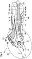
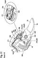
- FIG. 1 shows a cutting device 10 according to the invention.
- the cutting device 10 is designed as a garden cutting device.
- the cutting device 10 is designed as a pair of secateurs.
- the cutting device is designed as a battery-operated cutting device 10.
- another design of the cutting device 10 would also be conceivable, for example as a carpet or sheet metal snips or the like.
- the cutting device 10 has two cutting elements 12, 14 movable relative to one another ( Figure 2 , 3 ).
- the cutting elements 12, 14 are pivotable relative to one another.
- a first cutting element 12 is designed as a passive cutting edge with a cutting edge.
- the second cutting element 14 is designed as an active cutting edge with a blade.
- the cutting device 10 has two grip elements 16, 18 which can be moved relative to one another.
- the grip elements 16, 18 are pivotable or rotatable relative to one another.
- the grip elements 16, 18 are designed to be pivotable with respect to one another via at least one swivel joint 42.
- the cutting elements 12, 14 are also designed to be pivotable with respect to one another via the rotary joint 42.
- the swivel joint 42 is arranged between the grip elements 16, 18 and the cutting elements 12, 14.
- the first grip element 16 and the first cutting element 12 are connected to one another and arranged on different sides of the swivel joint 42. Furthermore, the second grip element 18 and the second cutting element 14 are at least indirectly connected to one another and are arranged on different sides of the swivel joint 42.
- a force transmission element 800 here in the form of a lever 80, connects the second cutting element 14 with the second grip element 18.
- the grip elements 16, 18 are provided to be gripped by an operator.
- the grip elements 16, 18 are provided to be gripped by an operator with the same hand. In principle, however, it would also be conceivable that the cutting device 10 is provided for two-handed operation. For example, further lever and / or translation elements could be provided in order to change a cutting force F cut at least partially relative to the force applied to the grip elements 16, 18, in particular an operating force F user .
- an opening spring 50 is arranged between the grip elements 16, 18.
- the opening spring 50 is arranged closer to the swivel joint 42 than to a free end of the gripping elements 16, 18 in relation to a longitudinal extension of the grip elements 16, 18.
- the opening spring 50 is designed as a compression spring.
- the ends of the opening spring 50 are supported on the first and second grip elements 16, 18.
- the opening spring 50 is provided to press the grip elements 16, 18 apart and thereby open the cutting device 10.
- the opening spring 50 is also provided to receive and / or guide a drive force transmission element 340, which is in operative connection with a drive unit 20, here in the form of a cable 34, in a cavity formed by it, as will be explained further below.
- a protective device 300 is also arranged between the opening spring 50 and the swivel joint 42.
- the protective device 300 extends between the two handle elements 16, 18.
- the protective device 300 is advantageously firmly connected to the second handle element 18.
- the protective device 300 is also movably received in the first grip element 16.
- the protective device can be designed, for example, as a telescopic device or as a rigid device.
- the protective device 300 is provided to protect at least one cable (not shown) of the cutting device 10, which is routed, for example, from the first to the second handle element 16, 18, from external influences and / or securely between the first and second handle element 16, 18 to include.
- the cable is, for example, a cable for the electrical connection of an energy storage unit 54 and a control unit 52 and / or a drive unit 20 or a sensor cable which goes from a 401 to the control unit 52 is performed.
- the protective device 300 also narrows an otherwise free space 301 between the swivel joint 42 and the opening spring 50 or at least partially fills it, so that, for example, an operator can inadvertently stick his finger into this space with difficulty or cut material, for example A twig or branch finds it difficult to get caught in this space.
- the protective device 300 is also a locking device for the gap 301.
- the gap 301 between the swivel joint 42 and the opening spring 50 is particularly dangerous for crushing an object 17, in particular the fingers or the skin of an operator, since they act in this area Forces due to the lever ratios or lever length of the grip elements 16, 18 around the swivel joint 42 are high.
- the protective device 300 can thus ensure that electronic components are guided in a protected and secure manner between the grip elements 16, 18. In addition, the protective device 300 serves to prevent injury.
- the cutting device 10 also has a drive unit 20.
- the drive unit 20 is designed as an electric motor.
- the electric motor is intended to be supplied with a voltage of less than 110 V, in particular with a voltage of 1 V to 36 V, preferably 3.6 V.
- the drive unit 20 is arranged in the first grip element 16.
- the drive unit 20 is arranged in a handle housing 44 of the handle element 16.
- the drive unit 20 is arranged on an end of the first grip element 16 facing away from the cutting elements 12, 14.
- the handle housing 44 has two housing shells in which the drive unit 20 is firmly received.
- the drive unit 20 is provided in at least one operating state to assist a movement of the second cutting element 14 relative to the first cutting element 12.
- the drive unit 20 is provided to support a closing movement of the cutting device 10 carried out via the grip elements 16, 18 during heavy cutting work. As a result, a force F user required by an operator to actuate the cutting device 10 can be reduced.
- the cutting device 10 also has a gear unit 38.
- the gear unit 38 is arranged in the first grip element 16.
- the gear unit 38 is arranged in the handle housing 44 of the handle element 16.
- the gear unit 38 is arranged on a side of the drive unit 20 facing the cutting elements 12, 14. In the present case, the gear unit 38 is driven directly by the drive unit 20. Power is transmitted from the drive unit 20 to the gear unit 38 via an output shaft 21 of the output unit 20 to a pinion 82 of the gear unit 38.
- the gear unit 38 is designed as a gear unit.
- the gear unit 38 has at least one gear stage.
- the gear unit 38 advantageously has several gear stages.
- the gear unit 38 has in particular one to six gear stages, advantageously four gear stages.
- the at least one gear stage is designed as a planetary gear stage 381, 382, 383, 384.
- the gear unit 38 is designed as a planetary gear unit ( Figure 4 ).
- the gear ratio of the gear unit 38 advantageously has a ratio of 30: 1 to 300: 1, in particular 100: 1 to 150: 1, in particular 130: 1. In principle, however, another translation would also be conceivable.
- the gear unit 38 is mounted in the handle element 16 via a housing 74 of the gear unit 38.
- the housing 74 of the gear unit 38 is formed by at least one ring gear 385 of the at least one planetary gear stage 381, 382, 383, 384.
- the housing 74 of the gear unit 38 can also be formed from individual serially arranged ring gears of the planetary gear stages 381, 382, 383, 384.
- the power transmission within the at least one planetary gear stage 381, 382, 383, 384 takes place in each case from a driven sun gear 386 via planets 387 of the respective planetary gear stage, which are supported on a stationary ring gear 381, to a planet carrier 388 rotating with the planets 387.
- the planet carrier 388 in turn drives a sun gear of the next gear stage 382, 383, 384.
- the planet carrier 389 of the last gear stage 384 forms the output of the gear unit 38.
- the cutting device 10 also has a coupling unit 22 ( Figure 4 and 5 ) on.
- the clutch unit 22 is designed as a self-shifting clutch unit 22.
- a “self-shifting clutch unit” should be understood to mean, in particular, a clutch unit 22 which is actuated free of external, for example electrical, switching signals, in particular a control unit 52.
- a coupling unit should preferably be underneath 22, which is actuated for a change between the clutch states free of explicit switching signals.
- This should preferably be understood to mean a clutch unit 22 which is actuated on the basis of mechanical influencing factors.
- the clutch unit 22 can therefore in particular be designed to be speed-operated, torque-operated, direction-operated and / or force-flow-operated.
- the self-shifting clutch unit 22 is designed as an overrunning clutch.
- an “overrunning clutch” is to be understood as meaning, in particular, a self-shifting clutch which is designed to be directionally actuated and / or actuated by force flow.
- the overrunning clutch is preferably at least directionally actuated.
- the overrunning clutch is preferably provided to open and / or close depending on a direction of rotation, in particular a drive and / or output side of the clutch unit 22, and / or depending on a direction of a force acting on the overrunning clutch.
- the overrunning clutch is preferably provided to open or close the drive unit 20 in at least one operating state depending on a direction of rotation, in particular a drive and / or output side, and / or depending on a direction of a force acting on the overrunning clutch.
- the coupling unit 22 is arranged in the first grip element 16.
- the coupling unit 22 is arranged in the handle housing 44 of the first handle element 16.
- the coupling unit 22 is provided for decoupling the drive unit 20 in at least one operating state in which the drive unit 20 is deactivated.
- the drive unit 20 is to be automatically deactivated and the coupling unit 22 is to be automatically decoupled if the drive unit 20 does not rotate.
- a “decoupling of the drive unit” is to be understood in particular as a decoupling of the drive unit 20 from a closing mechanism of the cutting device 10.
- the clutch unit 22 is in at least one operating state in which the drive unit 20 is deactivated, also provided for decoupling the gear unit 38.
- the coupling unit 22 is provided at least for realizing a complete manual operation to decouple the drive unit 20 and / or the gear unit 38.
- “complete manual operation” is to be understood in particular as an operating state in which the cutting device 10 is operated without any assistance from the drive unit 20.
- this is to be understood as an operating state in which the drive unit 20 is decoupled and therefore cannot be used to support a movement of the second cutting element 14 relative to the first cutting element 12.
- an advantageously smooth manual operation of the cutting device can in particular be made possible.
- the cutting device 10 can advantageously also be used without the drive unit 20, for example when there is no power supply and / or during light cutting work.
- the coupling unit 22 is advantageously provided to accelerate the opening or spreading movement of the two cutting elements 12, 14 or the two grip elements 16, 18.
- the coupling unit 22 enables an accelerated rolling up and / or unrolling of a drive force transmission element 340, here in the form of a cable 34, from a cable winch 32 or cable drum 320 of a cable winch 32 when the cutting device 10 is opened or spread, as described further below becomes.
- a drive force transmission element 340 here in the form of a cable 34
- the operating speed of the cutting device or the processing speed can be increased and the operating convenience can be increased.
- the number of possible cuts per unit of time can be increased.
- the coupling unit 22 is provided to decouple the drive unit 20 and to couple it again with a renewed closing movement with motorized power assistance .
- the coupling unit 22 has an inner rotating element 46 and an outer rotating element 48.
- the inner rotating member 46 is relative in at least one state rotatable to the outer rotating element 48.
- the outer rotary element 48 is advantageously connected to the output of the gear unit 38.
- a part of the clutch unit 22 advantageously forms a part, in particular of the last gear stage 384 of the gear unit 38.
- the outer rotary element 48 is advantageously designed in one piece with one part of the gear unit 38, in particular the planet carrier 389 of the last gear stage 384 and / or the output of the gear unit 38.
- the inner rotating element 46 and the outer rotating element 48 are secured to one another by means of an in particular coaxial connecting element 47.
- the connecting element 47 is designed as a connecting pin.
- the connecting element 47 secures the inner and outer rotary elements 46, 48 at least axially and / or radially to one another.
- the connecting shaft 47 is preferably firmly, in particular frictionally connected, to the outer rotary element 48 and at least with rotational play to the inner rotary element 46.
- the connecting shaft 47 is received on the inner rotary element 46 in a sliding bearing.
- the connecting shaft 47 also has a shoulder 471 for axially securing the inner rotary element 46 with respect to the outer rotary element 48.
- the shoulder 471 is supported on an in particular rim-like surface of the inner rotary element 46.
- the coupling unit 22 has several clamping bodies 24 ( Figure 6 and 7th ).
- a "clamping body” is to be understood in particular as an element of the coupling unit 22 which, in at least one operating state, in particular in a closed state of the coupling unit 22, is provided to clamp between two rotating elements of the coupling unit 22 that are rotatably mounted to one another.
- the clamping bodies 24 are arranged between the inner rotating element 46 and the outer rotating element 48.
- the clamping bodies 24 are arranged one behind the other in the circumferential direction around the inner rotary element 46.
- the clamping bodies 24 are designed as cylinders and / or rollers, in particular as cylindrical rollers.
- the outer rotary element 48 has a plurality of ramps 49 following one another in the circumferential direction on its inside. A number of ramps 49 corresponds to a number of clamping bodies 24.
- the clamping bodies 24 are movable between the ramps 49 arranged, the clamping bodies 24 being entrained when the outer rotary element 48 is rotated. If the outer rotating element 48 is driven in the circumferential direction against a ramp slope, the clamping bodies 24 roll into a narrower region between the outer rotating element 48 and the inner rotating element 46 and are pressed against the inner rotating element 46. This takes place when the outer rotary element 48 is driven in the drive direction 41.
- a "drive direction” is to be understood in particular as a direction of rotation of the drive unit 20 in which the drive unit 20 rotates in regular operation, in particular to support a cutting movement.
- the inner rotary element 46 is rotationally driven. In this state, the coupling unit 22 is closed, as in FIG Figure 6 is shown. If, on the other hand, the inner rotary element 46 is driven, regardless of a direction of rotation, the clamping bodies 24 remain in a valley of the ramps 49 or roll back into this and are spaced apart from the outer rotary element 48. The clamping bodies 24 are arranged freely between the rotating elements 46, 48. There is no rotary drive.
- the coupling unit 22 is opened in this state, as in FIG Figure 7 is shown.
- the outer rotary element 46 is driven by the drive unit 20 via the gear unit 38.
- the gear unit 38 and the drive unit 20 form a drive side of the coupling unit 22. If the inner rotary element 46 is driven counter to a drive direction 41, the clamping bodies 24 are moved into the valley of the ramps 49 and are also arranged freely between the rotary elements 46, 48.
- the self-shifting clutch unit 22 is spatially arranged between the cutting elements 12, 14 and the drive unit 20.
- the self-shifting clutch unit 22 is spatially arranged between a cable winch 32 and the gear unit 38. At least the cable winch 32 or an output element of the because winch 32 forms an output of the coupling unit 22
- the self-shifting clutch unit 22 has a cage 26 accommodating the clamping bodies 24 ( Figure 6 , 7th ).
- the cage 26 receives the clamping bodies 24 in receiving areas that are separate from one another.
- the cage 26 is used to position and guide the clamping bodies 24 in the circumferential direction.
- the cage 26 is provided for the purpose of spacing the clamping bodies 24 apart from one another in the circumferential direction and distributing them evenly. In particular, with a plurality of clamping bodies 24 it can be achieved that the clamping bodies 24 are in the circumferential direction perform the same movement.
- a controlled clamping of the clamping bodies 24 can preferably be made possible.
- the cage 26 is partially annular.
- the cage 26 is partially cylindrical.
- a plurality of axially protruding, circular segment-shaped webs are applied, which extend in the circumferential direction between the clamping bodies 24.
- the cage 26 is mounted on the inner rotating element 46 of the coupling unit 22.
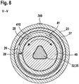
- the clutch unit 22 has a braking element 28, which is provided to brake the cage 26 ( Figure 8 ).
- the braking element 28 is designed as a spring element.
- the braking element 28 is designed as a type of spiral spring.
- the braking element 28 is designed as a loop spring.
- One end of the braking element 28 is fixedly arranged in a recess 29 of the cage 26.
- the braking element 28 extends at least partially in the circumferential direction in a spiral shape around the cage 26.
- the braking element 28 wraps around the cage 26.
- An outer surface of the braking element 28 is supported at least partially on a securing element 27 radially surrounding the braking element 28 or the cage 26.
- the securing element 27 is designed as a securing ring or fixing ring.
- the securing element 27 is arranged in a fixed manner on the coupling unit 22.
- the securing element 27 is firmly, in particular at least rotationally fixed, preferably frictionally connected to the housing 23 of the coupling unit 22.
- the inner surface of the housing 23 is structured, in particular corrugated, in the area of the area provided for the arrangement of the securing element 27.
- the braking element 28 enables the cage 26 to rotate relative to the fixed handle housing 44 in one direction of rotation, in particular a drive direction of rotation, and blocks rotation of the cage 26 in the opposite direction of rotation.
- the braking element 28 enables the cage 26 to rotate relative to the housing 23 of the coupling unit 22 or to the securing element 27 in one direction and blocks a rotation of the cage 26 in the opposite direction of rotation.
- the brake element 28 is designed to enable the cage 26 to run freely.
- the braking element 28 is designed to brake the cage 26 in the opposite drive direction 410 or to inhibit rotation or to fix the cage and to enable a rotation of the cage 26 relative to the outer support surface or the securing element 27 in the drive direction 41, in particular to enable it to be made with little friction.
- This type of loop coupling drags its free end when the cage 26 rotates in the drive direction 41 and slides on the inner surface of the securing element 27.
- the braking element 28 is provided to prevent undesired rotation of the cage 26.
- the braking element 28 is provided to prevent rotation of the cage 26 until a force is exerted, in particular a force is exerted by the drive unit 20.
- the braking element 28 can also be designed as a pawl element, another element generating a freewheel or the like.
- the inner rotary element 46 has at least one, in particular two, form-fit elements 460, 460 ′.
- the form-fit element is designed as a flange, but can also have a different shape.
- the cage 26 also has a form-fit element 260.
- the rotating body 370 has a form-fit element 370.
- the securing element 27 has at least one form-locking element 270. At least via the form-locking elements 260, 270, 370, 460, 460 'and sometimes frictional connections between the rotating body 37 and the inner rotating element 46, elements of the coupling unit 22 and the resetting unit 31 are securely connected to one another. This ensures that these elements are axially secured to one another.
- the axial securing can also be done in other ways.
- outer rotary element 48 is also axially secured to the inner rotary element 46 via the connecting element 47 and is thus positioned axially to the coupling unit 22 via the securing element 27.
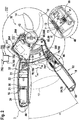
- the cutting device 10 has a reset unit 31 ( Figure 9 ).
- the reset unit 31 is arranged in the first grip element 16.
- the reset unit 31 is advantageously arranged in the handle housing 44 of the handle element 16.
- the reset unit 31 is arranged in the clutch unit 22.
- the reset unit 31 is preferably provided for a voltage of the rope.
- the resetting unit 31 is preferably provided to act on the cable winch 32 with a force, in particular with a force in the circumferential direction.
- the resetting unit 31 is particularly preferably provided to exert a tensile force on the cable 34 via the cable winch 32. In particular, the cable 34 is to be kept permanently under tension via the reset unit 31.
- the restoring unit 31 preferably effects a restoring force F vs which is less than an opening force F os of the opening spring 50 (FIG. 3).
- tension of the cable 34 can be ensured in particular even in the case of complete manual operation. In this way, undesired knotting of the rope 34 can advantageously be prevented.
- the rope 34 can be wound up without being driven.
- the resetting unit 31 has a spring element 36 and a rotating body 37. One end of the spring element 36 is firmly connected to the housing 23 of the coupling unit 22. The other end of the spring element 36 is firmly connected to the rotating body 37. The spring element 36 is arranged radially between the housing 23 of the coupling unit 22 and the rotating body 37.
- the spring element 36 surrounds the rotating body 37 radially.
- the spring element 36 is wound around the rotating body 37 several times.
- the reset unit 31 is connected at least indirectly to the cable winch 32 in particular via the rotating body 37.
- the rotating body 37 is fixed rotatably to a limited extent relative to the handle housing 44 or the housing 23 of the coupling unit 22 via the spring element 36.
- the rotating body 37 is connected to the cable winch 32 via a shaft 35.
- the rotating body 37 is advantageously connected in a rotationally fixed manner to the inner rotating element 46 of the coupling unit 22 via the shaft 35.
- the rotating body 37 can be connected to the inner rotating element 46 via at least one radial and / or axial positive-locking element.
- the rotating body 37 has a coaxial recess.
- the recess is polygonal.
- the inner contour of the recess is designed to correspond to the outer contour of the shaft 35.
- the spring element 36 is provided to apply a force to the shaft 35 in the drive direction 41.
- the spring element 36 is provided for the purpose of applying a force to the inner rotary element 46 in the drive direction 41.
- the spring element 36 is provided to transmit a tensile force to the cable 34 via the cable winch 32.
- the cable 34 is to be kept permanently under tension, in particular tensile tension, via the spring element 36.
- the spring element 36 can be pretensioned and fixed relative to the housing 23 of the coupling unit 23 with an assembly aid 360.
- the reset unit 31, in particular in connection with the clutch unit 22, can be installed preloaded as an assembly.
- the coupling unit 22 can also be opened via the spring element 36 as soon as the drive motor is deactivated.
- the inner rotary element 46 can thus be rotated in the drive direction 41 via the spring element 36, whereby the cage 26 can in turn be braked via the braking element 28 as soon as the drive motor 20 is deactivated.
- an alternative reversal of the direction of rotation of the drive motor 20 for opening the clutch unit 22 can advantageously be avoided.
- the cutting device 10 also has a cable winch 32 that can be driven by the drive unit 20.
- the cable winch 32 is arranged in the first grip element 16.
- the cable winch 32 is preferably designed to be drivable by the drive unit 20 via the coupling unit 22.
- the cable winch 32 is preferably designed such that it can be decoupled from the drive unit 20 via the coupling unit 22 in at least one operating state.
- An advantageous force action of the drive unit 20 can be achieved by the cable winch 32.
- a support for a movement of the second cutting element 14 relative to the first cutting element 12 can thereby be made possible in a structurally simple manner. An operator can thus advantageously be supported by the drive unit 20 during a closing movement.
- the cable winch 32 is arranged in the handle housing 44 of the first handle element 16.
- the cable winch 32 is arranged on a side of the coupling unit 22 facing the cutting elements 12, 14.
- the cable winch 32 is connected to the shaft 35.
- the shaft 35 is advantageously formed in one piece with the cable winch 32.
- the shaft 35 is supported by bearings, in particular sliding bearings 77, 77 '.
- the bearing 77 facing the cutting elements 12, 14 is supported in the handle housing 44 of the handle element 16.
- the bearing 77 ′ facing away from the cutting element 12, 14 is supported in the housing 23 of the coupling unit 22.
- the shaft 35 is connected to the coupling unit 22.
- the shaft 35 is connected in a rotationally fixed manner to the inner rotary element 46.
- the shaft 35 is also rotatably connected to the rotating body 37.
- the shaft 35 has a polygonal profile. It can also have a different profile for connecting to the coupling unit 22, for example a square, tongue and groove profile or another shaft-hub connection profile. Because the cable winch 32 is connected directly to the inner rotary element 46 of the coupling unit 22 and the rotary body 37 of the reset unit and also connects these two elements to one another, the device is very compact.
- the self-shifting clutch unit 22 can also be partially integrated into the cable winch 32.
- the coupling unit 22 can be partially encompassed by the cable winch 32.
- the cable winch 32 forms an output side of the coupling unit 22.
- the cable winch 32 has a cable drum 320.
- the cable drum 320 is essentially cylindrical.
- An axial extension of the cable drum 320 can be provided to only roll up the cable 34 in one layer. In principle, however, a multi-layer roll-up is also possible. By coating the rope 34, this can also be done without wear.
- the axial extension of the cable drum 320 is advantageously 5-15 mm, in particular 6 mm.
- the latter forms a shoulder at least on the side facing the rotary joint 42.
- the diameter of the cable drum 320 is advantageously less than 10 mm, in particular 7 mm.
- the cable winch 32 has a receptacle 33 for fixing the cable 34.
- the receptacle 33 is designed as an opening or as a through hole in the transverse axis direction of the cable winch 32 or shaft 35.
- the through hole has an at least substantially rectangular cross section, but can also be round. The sides of the rectangle can be rounded in an arc shape.
- the receptacle 33 can also be oval, round, angular or the like. The transitions of the through hole to the surface of the cable winch 32 are rounded. As a result, the rope 34 does not suffer any injuries when it is rolled up.
- the receptacle 33 can be designed as a press fit.
- the through hole is selected in coordination with the cable 34 with regard to its dimensions in such a way that it enables a loop to be passed through.
- it is dimensioned in coordination with the rope 34 such that it does not allow a thickening in the rope, in particular a knot, very particularly preferably a diamond knot attached to one end of the rope, to pass through.
- the knot is thus held at least positively on the receptacle 33.
- it can also be held by friction.
- the rounding of the receptacle 33 is formed under load of the rope 34 from a press fit. This strengthens the stability of the knot, allows it to protrude less and / or prevents unintentional opening.
- the shaft 35 advantageously has a larger diameter than in the area of the cable drum 320. This is advantageously 8 mm. In principle, however, the area of the receptacle 33 can also function as a cable drum.
- the cutting device 10 also has the rope 34.
- the rope 34 is preferably fixed to the second grip element 18 by means of the loop on the lever 80. It is attached to the first grip element 16 via the knot and the receptacle 33 on the cable winch 32.
- the rope 34 is preferably arranged closer to the swivel joint 42 with respect to the gripping elements 16, 18 than to the ends of the gripping elements 16, 18 spaced from the swivel joint 42, in particular closer than 10 cm, preferably between 6 and 8 cm from the swivel joint 42. It is stretched between the grip elements 16, 18.
- the cable 34 can be mounted in the first grip element 16 and / or second grip element 18 via a guide element 780, in particular a guide sleeve 78.
- the guide sleeve 78 is advantageously designed as a hollow cylinder and has a flange 783 on one side.
- the flange 783 can advantageously be provided for fixing on the first or second grip element 16, 18.
- the guide element 780 can position and / or fix the opening spring 50 on the first and / or second grip element 16, 18.
- the cylinder of the guide sleeve 78 is oriented in particular transversely to the longitudinal extension of the grip element 16, 18, in the direction of the opposite grip element 16, 18.
- An outer surface 784 of the cylinder supports the inner side or inner surface of the opening spring 50.
- a rounding 782 is provided on at least one opening, in particular on both openings of the guide sleeve 78.
- a radius of the rounding 782 is advantageously 1.5 mm.
- the inner diameter of the cylinder can widen conically in the direction of the flange 783.
- the cable 34 advantageously only touches the guide element 780 at the opening of the guide element 780 facing the other handle element 16, 18, which also serves to support the cable 34 on the guide element 780 with little friction and to support the cable 34 without contact within the opening spring 50 and / or allows the rope 34 to be rolled up over the entire width of the drum, as it were.
- the rope 34 is between the two grip elements 16, 18 stretched.
- the ends of the opening spring 50 are received on the guide sleeves 78 in the first and second grip elements 16, 18.
- the guide sleeves 78 can be formed from a stronger material than the grip elements 16, 18.
- the opening spring 50 is designed as an evolute spring, in particular as a double volute spring.
- the opening spring 50 preferably has a length of less than 100 mm, in particular 70 mm, in the relaxed state. In the compressed state, the opening spring 50 has a length of less than 25 mm, in particular 17 mm. In the compressed state, the opening spring 50 has an opening force of less than 100 N, in particular 32 N, for example.
- a diameter of the spring is, for example, 4 to 8 mm, in particular 6.6 mm, at the ends and around 10 to 15 mm, in particular 11 mm, in the middle of the opening spring 50.
- the opening spring 50 is advantageously provided to allow an opening angle ⁇ of the grip elements 16, 18 around the rotary joint 42 of up to 70 °, in particular of up to 50 ° and particularly preferably of up to 35 °.
- the cable 34 can be mounted with low friction within the opening spring 50.
- the cable 34 can be guided within the opening spring 50 with little injury, so that damage to the cable through, for example, sharp edges of the opening spring 50 is avoided.
- the opening spring 50 can have additional guide elements 781, which guide the cable 34 within the opening spring 50 in a protective and low-friction manner.
- the rope 34 is advantageously made from polyethylene, in particular from polyethylene with an ultra-high molar mass (UHMW-PE). It is a Dyneema® rope 34. It advantageously has a diameter of 2 mm and can withstand, for example, a repeated tensile force of> 1000 N as well as being rolled up on the rope drum 320. Such a rope 34 is particularly resistant to abrasion.
- the rope 34 can also be formed from polyacrylic, Kevlar, wire or the like.
- the rope 34 is connected at least indirectly to the second grip element 18 in an area between the swivel joint 42b and an end of the second grip element 18 facing away from the cutting elements 12, 14. It can be via the driving force transmission element 340 exert a support force to close the cutting elements 12, 14 on them.
- the cable 34 is connected to the second grip element 18 via the force transmission element in the form of the lever 80.
- the rope 34 can be variably wound onto the rope winch 32. Because the cable 34 is guided in the opening spring 50, it can advantageously be prevented that an operator is disturbed by the cable 34 when operating the cutting device 10. In addition, damage, soiling, exposure to weathering, injury to the rope 50 and / or the like can be avoided, in particular through the use of the evolute spring.
- a free length of the cable 34 can be varied via a drive of the cable winch 32, or a distance or opening angle ⁇ of the grip elements 16, 18 and / or an opening angle of the cutting elements 12, 14 can be varied ( Figure 2 , 3 ).
- a drive train for the power-assisting operation of the handheld power tool is advantageously formed from the following elements: drive motor 20, gear unit 38, clutch unit 22, reset unit 31 and cable winch 32. These elements are arranged in series, in particular in the order mentioned above. They are preferably arranged in the first grip element 16. If necessary, the drive motor 20 drives the gear unit 38, which drives the cable winch 32 via the coupling unit 22.
- the reset unit 31 keeps the cable 34 permanently under tension and, in conjunction with the elements of the coupling unit 22, can be provided for decoupling the coupling unit 22 when changing from power-assisted to non-power-assisted operation.
- the drive train is advantageously only supported or fixed in the handle housing 44 via the housing of the motor unit 20, the housing 74 of the gear unit 38, the housing 23 of the coupling unit 22, and the rotary bearing 77 of the cable winch 32 facing the cutting elements 12, 14.
- the coupling unit 22 and the resetting unit 31 are very compact and allow easy assembly.
- the first grip element 16 can at least as a result be made compact or short.
- An extension of the first or second grip element 16, 18 between an end of the first or second grip element 16, 18 facing away from the swivel joint 42 and the opening spring 50 is less than 150 mm, in particular 120 to 130 mm.
- An extension of the first or second grip element 16, 18 from the end facing away from the rotary joint 42 to the rotary joint 42 is advantageously less than 200 mm, in particular 170 to 190 mm.
- the total extension of the cutting device 10 is advantageously less than 300 mm, in particular 200 to 300 mm, preferably 250 to 260 mm.
- An enveloping circle diameter around the first grip element 16 in the grip area 62 is advantageously less than 40 mm, in particular 30 to 35 mm.
- An enveloping circle diameter around the second grip element 18 in the grip area is advantageously less than 30 mm, in particular around 25 mm.
- the haptics and / or ergonomics of a non-motorized, purely manual cutting device are achieved with the cutting device 10.
- the arrangement of the drive train and the arrangement of the energy storage unit 54 in at least one of the grip elements 16, 18 are made possible.
- At least one of the grip elements 16, 18 has at least at the transitions between the inside 600 of the grip and the side surfaces 610 of the at least one grip element 16, 18, an at least partially elastic and / or beveled and / or rounded area 620 ( Figure 1 ).
- the area can be set back in relation to the side surface 610 in the direction of a dividing plane of the housing shells of the at least one grip element 16, 18.
- the inner handle sides 600 mean, in particular, the inner handle surfaces facing each other.
- An opening angle ⁇ of the beveled areas 620 of both grip elements 16, 18 to one another is advantageously between 30 ° and 150 °, or the angle between an imaginary parting plane between the grip elements 16, 18 and a beveled area 620 of the first or second grip element 16, 18 Half of it.
- the opening angle ⁇ between the rotary joint 42 and the ends of the grip elements 16, 18 facing away from the rotary joint 42 varies at least between 60 ° to 120 °.
- a leg length s of the beveled surface is advantageously 5 to 10 mm and can also vary in length.
- a spacer element 630 in particular a soft stop element, is provided on the inner grip surfaces.
- the outside 64 of the grip elements 16, 18 is advantageously also rounded, in particular rounded in accordance with the above-mentioned enveloping circle diameter of the respective grip element 16, 18.
- the outside 64 advantageously has a soft grip surface in order to increase the ease of use and / or a structure in order to prevent slipping during operation.
- the grip elements 16, 18 are provided for this purpose at least almost touching each other.
- An enveloping circle diameter around the closed cutting apparatus 10 is advantageously less than 100 mm, in particular an enveloping circle diameter around the grip area 62 of the closed grip elements 16, 18 is less than 70 mm, preferably 50 to 60 mm.
- the cutting device 10 also has a control unit 52.
- the control unit 52 is arranged in the first grip element 16.
- the control unit 52 is arranged in the handle housing 44 of the handle element 16.
- the control unit 52 is provided for controlling the drive unit 20. In principle, both a pure control of the drive unit 20 and a regulation of the drive unit 20 can take place.
- the control unit 52 supplies the drive unit 20 with energy.
- the drive unit 20 can also be connected directly to the energy storage unit 54 via the switch 72.
- the control unit 52 is arranged between the drive unit 20 and the swivel joint 42.
- the control unit 52 is arranged between the cable winch 32 and the swivel joint 42.
- the control unit 52 is advantageously connected to a display element 200.
- the display element 200 indicates an activation or operation of the drive unit 20, but can also enable another form of status display.
- the display element 200 is a light.
- the light is an LED.
- the display element 200 can use the light color, for example, to show an operator information about the charge status of an energy storage unit 54, the assistance force during an assistance mode or the like and / or indicate whether an assistance mode is active or not.
- the control unit 52 is connected to the energy storage unit 54.
- the drive unit 20 can be supplied with energy from the control unit 52 via the energy storage unit 54.
- the energy storage unit 54 has at least one battery cell.
- the battery cell 58 is formed from lithium-ion cells. In principle, however, a different design of the at least one rechargeable battery cell 58 would also be conceivable.
- the battery cell 58 is arranged in the second grip element 18.
- the Battery cell 58 is arranged in a handle housing 60 of the second handle element 18.
- the battery cell 58 is connected to the control unit 52 ( Figure 2 , 3 ).
- the battery-operated handheld power tool or cutting device 10 also has a blocking device 202.
- the blocking device 202 is arranged on the first grip element 16.
- the blocking device 202 is arranged in the handle housing 44 of the handle element 16.
- Figure 11 shows a section of the cutting device 10 or the blocking device 202 in a first state.
- the cutting elements 12, 14 of the cutting device 10 are in a closed state.
- the blocking device 202 is in a first position.
- the blocking device 202 blocks an actuation and / or tool movement of the cutting device 10 relative to one another, in particular the cutting elements 12, 14 or grip elements 16, 18.
- the blocking device 202 is designed as a mechanical blocking device 202.
- the blocking device 202 has a slide switch 204.
- the slide switch 204 is intended to block and / or close or release a charging interface 211.
- the slide switch 204 is provided to be moved by an operator, in particular by a finger of an operator.
- the blocking device 202 has a latching element 206.
- the latching element 206 is provided to mechanically block or release a relative movement of the two cutting elements 12, 14 to one another.
- the slide switch 204 is mechanically connected to the latching element 206.
- the slide switch 204 is connected to the latching element 206 via a swivel joint 208.
- the blocking device 202 is arranged in the area of the control unit 52.
- the blocking device 202 is arranged in the area of a thickening of the grip element 16.
- the blocking device 202 or the slide switch 204 of the blocking device can advantageously be actuated with one-handed operation of the cutting device 10 at least with one thumb of the operator.
- the slide switch 204 is guided or mounted in a longitudinally displaceable manner via grooves 207 in the handle element 16.
- the slide switch 204 can be moved relative to the handle element 16.
- the slide switch 204 is designed to close or at least partially open an opening 209 in the handle housing 44.
- the slide switch 204 is provided to cover the charging interface 211 or to close or release.
- the slide switch 204 is provided to enable the charging interface 211 in the first position and to close the charging interface 211 in a second position.
- the locking element 206 is connected to the swivel joint 208 at a free end.
- the latching element 206 has a locking element 210 at the other free end.
- the latching element 206 is designed to engage in a first and a second recess 212, 214 of the first and second cutting elements 12, 14 by means of the locking element 210, provided the cutting elements 12, 14 are in a closed state. In the closed state, the first and second recesses 212, 214 of the cutting elements 12, 14 are aligned in the direction of the axis of rotation 149 of the swivel joint 42.
- the latching element 206 or locking element 210 is provided in this position to engage in the aligned recess 212, 214.
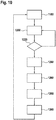
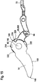
- Figure 12 shows the blocking device 202 in a second state.
- the blocking device 202 is in the second position.
- the cutting elements 12, 14 of the cutting device 10 are in an open position. In the second state, the cutting elements 12, 14 can be moved relative to one another.
- the cutting device 10 is in a state provided at least for manual operation.
- the blocking device 202 In the second position of the blocking device 202, the blocking device 202 enables an actuation and / or tool movement of the cutting device 10, in particular of the cutting elements 12, 14 or grip elements 16, 18 relative to one another.
- the charging interface 211 is blocked or closed by the slide switch 204 of the blocking device 202.
- the latching element 206 does not protrude into the recesses 212, 214 of the cutting elements 12, 14.
- At least one of the recesses 212, 214 can also be arranged in at least one structure connected to one of the cutting elements 12, 14 in a rotationally fixed manner.
- the recess 214 can also be arranged in the lever 80.
- a sealing element (not shown), which enables the charging interface 211 to be sealed, can be arranged both on the slide switch 204 and on the handle element 18. The sealing element is arranged in particular between the grip element 18 and the slide switch 204.
- the at least one sealing element advantageously ensures that the charging interface 211 is sealed in the second position of the blocking device.
- the control unit 52 or other electronic components can thus also be advantageous of the cutting device 10, which are at least in electronic contact with the charging interface 211, are protected from dust and moisture, in particular during operation of the cutting device.
- the cutting device 10 furthermore has the force transmission element in the form of the lever 80.
- the lever 80 connects the second cutting element 14 to the second grip element 18.
- the lever 80 has at least one form-fit element for connection to the cutting element 14.
- the second grip element 18 is connected to the lever 80 via at least one further swivel joint 65.
- the grip element 18 and the lever 80 are designed to be pivotable relative to one another at least to a limited extent.
- the grip element 18 and the lever 80 pivot about the further swivel joint 65.
- the grip element 18 and the lever 80 are designed to be pivotable relative to one another about the pivot axis 66.
- the pivoting movement is limited at least via the inner contour of the hollow grip element 18.
- the pivoting movement can be limited by a form-fit element formed in the grip element 18.
- the grip element 18 is also supported against the lever 80 by means of a spring 68.
- the grip element 18 is supported against the lever 80 at a free end of the lever 80 by means of the spring 68
- the cutting device 10 also has a sensor 401.
- the sensor 401 is designed to sense an operating state in which a power assistance operation is required.
- the sensor 401 or other sensors can advantageously sense an operating state in which, for the purpose of operating safety of the cutting device, in particular when an object 17 is arranged between the grip elements 16, 18, support operation is to be suspended and / or switched off.
- the sensor 401 is preferably a force sensor 40 which is provided to sense a force acting on the second grip element 18, in particular relative to the first grip element 16 and / or relative to the lever 80.
- the force sensor 40 can preferably be provided both for to detect an exact force as well as simply exceeding a limit force.
- the force sensor 40 is arranged on the second grip element 18 and / or on the force transmission element designed as a lever 80.
- the force sensor 40 is advantageously arranged integrated in the second grip element 18.
- the force sensor 40 is arranged between the lever 80 and the grip element 18.
- the force sensor 40 has at least one spring 68 and a switch 72, in particular a microswitch.
- the spring 68 advantageously supports the lever 80 with respect to an outer side 64 of the second grip element 18. If a cutting force F cut acts on the cutting elements 12, 14 when the cutting device 10 is closed, for example to cut a cut material 11, the second grip element 18 can be moved relative to the force transmission element or to the lever 80 against the spring force F gs of the spring 68 are, in particular pivoted.
- the lever 80 and the grip element 18 are arranged so as to be pivotable about the further common swivel joint 65.
- the spring 68 so to speak, couples the grip element 18 to the lever 80 in at least one operating state.
- the lever 80 has a recess and the handle element 18 has an extension which, in particular when connecting two handle shells of the second handle element 18, forms an axis of rotation 66 about which the lever 80 can rotate or pivot at least to a limited extent.
- the grip element 18 can advantageously be pivoted to a limited extent around the axis of rotation 66 with respect to the lever 80.
- the pivot limitation is ensured by at least corresponding form-locking elements on the second grip element 18 and the lever 80.
- the spring 68 can also represent a pivot limitation, in particular the compressed spring 68.
- the second grip element 18 is advantageously supported at a free end of the lever 80 by means of the spring 68 against the lever 80.
- a receiving element 69 is advantageously pushed onto the lever 80.
- the receiving element 69 advantageously serves as a receptacle, in particular a guide receptacle for the spring 68, and advantageously as a receptacle for the switch 72, in particular as a plug receptacle.
- the handle element 18 pivots relative to the lever 80. In the present case, the outer side 64 of the handle element 18 approaches the lever 80.
- the force sensor 40 has a switch 72 to detect this pivoting movement or pivoting force or to detect at least one exceeding of a threshold value, a movement of the spring 68 and / or the like.
- the switch 72 is designed as a microswitch, in particular as an opener or changeover contact.
- the switch 72 has a release element designed as a pressure element.
- the pressure element is designed as a pivot element 71, in particular as a pivot lever. It is provided for actuation of the switch 72.
- the switch 72 advantageously senses a pivoting out or a distancing of the switch 72 from the inside 63 of the second grip element 18. The switch 72 is therefore activated when the pivot element 71 is pivoted out.
- the switch 72 is deactivated in a state in which the pivot element 71 is in contact with the switch 72 and activated in a state in which the pivot element 71 is pivoted out relative to the switch 72.
- the switch 72 closes when the pivoting element 71 is pivoted out in a defined manner.
- the pivoting element 71 can be supported directly on the housing of the handle element 18 or on an additional pressure element 81 or the like.
- the pressure element 81 can be designed in such a way that it is provided for selecting a sensitivity of the force sensor 40.
- the pressure element 81 is advantageously part of the force sensor 40, which is advantageously arranged on a further switch 73.
- the other switch serves as an assist operation setting element.
- the further switch 73 is advantageously designed to be displaceable transversely with respect to the pivot element 71.
- the further switch 73 can be moved in the direction of the swivel joint 42.
- the further switch 73 is arranged on the side of the second handle element 18 that faces the first handle element 16.
- the further switch 73 is thus arranged on the inside 63 of the second grip element 18. Inadvertent actuation of the further switch 73, in particular during a cutting process, can thereby be avoided.
- the further switch 73 is designed as a slide switch.
- the further switch 73 has a pressure element 81 on which is wedge-shaped.
- the pressure element 81 is intended to touch the pivot element 71 in all operating states.
- the sensitivity of the force sensor 40 or a threshold value for triggering the switch 72 can be varied. Due to the trigonometric distance relationship of the pressure element 81 to the pivot element 71, in particular over the lever length of the lever 80 within the second grip element 18, the sensitivity of the force sensor 40 can be changed when the further switch 73 is moved.
- the switch 72 is only activated when there is a higher operating force F user .
- the switch 72 is activated when the operating force F user is lower.
- the sensitivity of the force sensor can be reduced in a cost-effective manner using mechanical means 40 set.
- Different activation levels or threshold values for the support operation of the cutting device 10 can be set, for example as a function of a varying manual force of an operator.
- the further switch 73 advantageously has three latching positions in connection with the switch receptacle, in particular the handle element 18. This means that three levels of support operation can advantageously be defined.
- the design means that there is no need for an additional on / off switch to activate an alternative, purely electronic force or displacement sensor, which would require a permanent power supply in order to detect a defined threshold value being exceeded.
- the switch 72 and thus the assist drive are therefore advantageously only activated when a mechanical force of the spring 68 in the form of a threshold value is exceeded.
- a threshold value is exceeded as a function of the spring-loaded pivoting movement of the lever 80 within the grip element 18 around the rotary joint 67, so that the switch 72 is triggered.
- a particularly cost-effective and structurally simple force sensor 40 can be provided.
- the drive force transmission element 340 which is in operative connection with the drive unit 20, acts on the lever 80 in the form of the cable 34.
- the drive unit 20 When the drive unit 20 is activated, the drive force F an is applied to the lever and the closing movement of the cutting elements 12, 14 is supported.
- the lever 80 decouples the drive force F on from a direct force application on the handle element 18. If, for example, an object 17 is arranged between the handle elements 16, 18 during a force-assisting operation of the cutting device 10, the handle elements 16, 18 cannot move any further towards one another.
- the drive force F on moves the lever 80 within the handle element 18 in the direction of its starting position, the switch 72 is opened, and the power-assist mode is ended.
- the force sensor 40 or the lever 80, the spring 68 and the switch 72 thus decouple a force-assisting operation for pressing the handle elements 16, 18 together. If an object 17 is arranged between the handle elements 16, 18, the switch 72 is inevitably opened and the drive unit 20 is deactivated so that there can be no undesirable crushing, for example of a limb or the skin of an operator, or damage to the grip elements 16, 18, for example when a branch is arranged between them. In such cases, only the Operating force F user to a crushing of the object 17. Due to the arrangement of the lever 80 in the handle element 18, in particular an arrangement of an object 17 in the entire area between the further pivot joint 65 of the lever and the ends of the handle elements 16, 18 facing away from the pivot joint 42 can be recognized and the support operation can be switched off.
- An additional sensor (not shown here) for detecting an object 17 between the grip elements 16, 18 can be dispensed with.
- the force sensor 40 is advantageously required, which is triggered when the threshold value is exceeded in order to activate the support mode, and inevitably switches off the support mode at the moment when an object 17 is arranged between the grip elements 16, 18.
- the susceptibility to errors and the risk of injury, as well as the control effort to possibly have several alternative sensors for detecting the different operating cases - power-assist mode required, object 17 between the grip elements 16, 18 - is much lower.
- the force sensor 40 would nevertheless be conceivable.
- Alternative arrangements of the spring 68, the switch 72 or the further switch 73 for realizing the same functionality are also conceivable.
- a triggering force of the force sensor or sensors 40 could be freely defined by software.
- the force sensor 40 can differentiate between different degrees of depression of the switch 72 or the pivoting of the pivoting element 71 in order to be able to draw conclusions about an exact current operating force F user .
- the force sensor 40 is also connected to the control unit 52.
- the control unit 52 is provided for controlling the drive unit 20 as a function of a signal from the force sensor 40.
- the control unit 52 is provided to activate the drive unit 20 when a defined measured value of the force sensor 40 is overwritten.
- the control unit 52 is provided to activate the drive unit 20 when the switch 72 of the force sensor 40 is closed. Furthermore, the control unit 52 is provided to stop the drive unit 20 when the switch 72 of the force sensor 40 is opened.
- a direct connection of the output unit 20 to the energy storage unit 54 via the switch 72 and without the controller 52 is also conceivable.
- the second cutting element 14 is designed as an active cutting element 14 with a cutting edge. It is designed as an exchangeable cutting element 14.
- the second cutting element 14 is at least one form-fit element 216 ( Figure 11 , 12 ) connected to the lever 80 of the cutting device 10, which in turn is connected to the second handle element 18.
- the form-fit elements 216 are provided at least for the transmission of forces in the radial direction about the axis of rotation 420, but can also be designed for the transmission of axial forces F ax in the direction of the axis of rotation 420, on the lever 80 or the cutting element 14.
- a latching lug 220 is formed on the lever 80 and engages in the form-fitting element 216 of the cutting element 14 in the connected state.
- at least one axial guide surface 332 is provided for introducing the cutting element 14 into the cutting element receptacle 400.
- Figure 13 shows a section III-III 'through the cutting device 10 or the cutting element receptacle 400.
- the first and second cutting elements 12, 14 are connected indirectly via a shaft arranged along the axis of rotation 420.
- the shaft forms a swivel joint 42 for the cutting elements 12, 14.
- Die The shaft is formed by at least one connecting element 421.
- a spacer element 423 is also arranged on the connecting element 421.
- the spacer element 423 serves at least for the axial, in the present case also the radial spacing of the connecting element 421 from the cutting elements 12, 14.
- the spacer element 423 can be fixed to the connecting element 421 via a securing element 430.
- the connecting element 421 can also be formed in one piece with the spacer element 423.
- the connecting element 421 is designed as a screw.
- the screw can be loosened and advantageously removed together with the spacer element 423 from the cutting device 10 or the handle housing 44.
- the spacer element 423 is part of a control device 422 which, independently of a clamping force F clamp of the connecting element 421, effects a defined contact pressure F anpr of the cutting elements 12, 14 towards one another in the direction of the axis of rotation 420.
- the cutting elements 12, 14 have through bores 120, 140 in the direction of the axis of rotation 420, through which the connecting element 421 protrudes.
- the radial surfaces of the through bores 120, 140 form bearing surfaces which are arranged on a corresponding bearing surface of the spacer element 423 or a sleeve that radially encases the connecting element 421.
- the spacer element 423 at least indirectly defines a minimum distance between two clamping force transmission elements in the direction of the axis of rotation 420, here in the form of the screw head 443 of the screw and in the form of an abutment 425, the abutment being designed as a screw nut, in particular as a non-rotatable screw nut, with which the Screw is connected.
- These clamping force transmission elements transmit a pretensioning force F clamp of the connecting element 421 at least indirectly to the spacer element 423. Only a definable part of the clamping force F clamp is transmitted to the axial surfaces 121, 141 of the cutting elements 12, 14 by the spacer element 423.
- At least one axial position of the two cutting elements 12, 14 along the axis of rotation or a frictional force between the cutting elements 12, 14, which occurs when they are pivoted relative to one another, can be determined independently of a tightening torque of the connecting element 423 or independently of another influencing variable .
- a longitudinal expansion I of the spacer element 423 in the direction of the axis of rotation 420 allows a relative movement of the cutting elements 12, 14, in particular a pivoting movement of the cutting elements 12, 14 with respect to one another. They advantageously corresponds to at least the sum of the width dimensions b 1, b 2 of the two cutting elements 12, 14 along the rotational axis 420.
- control device can have an elastic element 424 that acts on the cutting elements 12, 14 with respect to one another with a defined axial force or clamping force F clamp along the axis of rotation 420.
- the elastic element 424 is designed as a spring, in particular as a compression spring, particularly preferably as a wave spring.
- the elastic element 424 is arranged indirectly between an axial surface 122 of the first cutting element 12 and a radial shoulder 426 of the spacer element 423.
- the elastic element is arranged between the axial surface 122 of the first cutting element 12 and a locking ring 427.
- the locking ring 427 is supported on the shoulder 426 of the spacer element 423.
- the securing ring 427 is also supported on the handle housing 44.
- the axial force F corresponds ax and acts as a pressing force F on or as pressure or normal force between the two cutting elements 12, 14.
- the elastic member 424 a friction force between the cutting elements 12, 14 one.
- a basic actuating force for closing the cutting device 10 can be established at least partially. This allows a basic distance between the cutting elements 12, 14 to be set. Regardless of the production width - within a tolerance band - of the cutting elements 12, 14, the contact pressure F on the cutting elements 12, 14 to one another remains almost constant due to the spring constant of the elastic element 424. Further tolerances of the cutting element receptacle 400 can also be compensated for.
- a sheet of paper and a branch can thus advantageously be cut by the cutting device 10, since the cutting gap can be adapted to the requirements given by the cut material 11.
- the second cutting element 14 can be replaced without readjusting the clamping force or a tightening torque of the screw or a variation of intermediate elements is possible. Irrespective of the clamping force or the tightening torque of the connecting element 423 or the screw, the contact pressure F on between the cutting elements 12, 14 remains almost constant.
- the wave spring advantageously has an external diameter in the range of 20 mm and an internal diameter in the range of 15 mm.
- a free axial length of the wave spring is advantageously less than 5 mm, in particular 3.25 mm.
- the clamping force of the wave spring is advantageously 15 to 25 N, with a compressed length of 1.1 to 1.5 mm.
- the connecting element 423 when the connecting element 423 is loosened and in particular when the connecting and spacing element 421, 423 is completely removed, the securing ring 427 is axially supported on the handle housing 44.
- the securing ring 427 is axially supported on the handle housing 44.
- at least a reduced axial force F ax of the spring or a contact pressure F on at least the first cutting element 12 is maintained.
- the second cutting element 14 to be exchanged can at least be positioned without a connecting element 421 and / or is secured against accidentally falling out of the cutting device 10.
- the first, in particular stationary, cutting element 12 is also designed to be transversely displaceable, that is to say displaceable in the direction of the axis of rotation 420. It is secured in the direction of rotation around the axis of rotation by form-fit elements. These are supported on corresponding form-fit elements in the first grip element 16. In particular, the corresponding form-locking elements are connecting elements for connecting the grip shells of the first grip element 16.
- the elastic element 424 also serves as an overload protection element of the cutting device 10. It prevents plastic deformation of the cutting elements 12, 14 when the cutting device 10 is in operation.
- the elastic element 424 sets a threshold value F ax above which the cutting element 10 is allowed to gap.
- F ax the threshold value
- the elastic element yields at least as far as the axial stop of the second cutting element 14 on a stop element 442 and thus enables at least slight axial displacement and / or tilting within the first grip element 16 or along the Axis of rotation 420.
- the elastic behavior and the desired gaping when a defined threshold value is exceeded can be set via the spring force of the elastic element 424 and the arrangement of the control device 422.
- the control device 422 comprises at least the connecting element 421, the spacer element 423, the securing ring 427 and the elastic element 424.
- the abutment 425 of the connecting element 421 in the form of the screw nut is firmly received in the handle housing 44 of the cutting device 10. It is held in a torsion-proof manner via a hexagonal form-fitting element 428.
- a cover 429 which is connected to the handle housing 44, secures the screw nut axially so that it is positioned on the cutting device 10 even when the connecting element 421 is removed.
- a sliding element 440 in the form of a sliding ring or a sliding washer is also arranged between the handle housing 44 and the lever 80. At least one fixing element 441 is connected to the handle housing 44 in a rotationally fixed manner.
- the sliding element 440 is also arranged between the spacer element 423 and the abutment 425 designed as a screw nut.
- the abutment is thus secured axially between the sliding element 440 and the cover 429, in particular when the connecting element 421 is removed.
- the sliding element 440 decouples a potential rotational movement of the spacer element 423 from the abutment 425.
- the control device 422 can be secured against rotation at one or more points, at least indirectly with the handle housing 44 and / or the stationary first cutting element 12, so that the relative movement of the lever 80 or first cutting element 12 does not lead to an unintentional loosening of the connecting element 421.
- the sliding element, the abutment 425 and / or the spacer element 423 are received on the handle housing 44 in a manner secured against rotation.
- a thickness of the first cutting element 12 is advantageously 4 mm.
- a thickness of the second cutting element 14 is advantageously 3.5 mm at its thickest point.
- a thickness of the lever 80 is advantageously 3.5 mm.
- Figure 14 shows a cutting element which is designed as the second cutting element 14 in a plan view and a side view.
- the second cutting element 14 has a blade 143.
- the second cutting element 14 is a replaceable cutting element for the cutting device 10.
- the second cutting element 14 has a tip 146 and an end 148 opposite the tip 146. In the area of the end 148, the second cutting element 14 has a recess 214.
- the recess 214 serves as a receptacle for a locking element 210 of the blocking device 202 of the cutting device 10 for blocking a movement of the cutting elements 12, 14 relative to one another.
- the second cutting element 14 has the form-fit element 216, which is designed as a counter-locking recess for the locking lug 220 of the lever 80 of the cutting device 10.
- the form-fit element 216 serves to transmit radial forces of the grip element 18, in particular via the lever 80, around the swivel joint 42 of the cutting device 10.
- the end 148 of the second cutting element 14 is also at least partially rounded.
- the second cutting element 14 has an insertion aid 144 in the form of an inclined surface between the end 148 of the second cutting element 14 and a receptacle 142, which is designed as a recess 140, which is provided for rotatably receiving the second cutting element 14 in the cutting device 10.
- the insertion aid 144 is beveled with respect to a cut surface plane of the second cutting element 14 formed by the cut surface 145, but can also be round, in particular convex.
- the insertion aid 144 runs essentially from the center of the receptacle 142 in the radial direction to the end 148 of the second cutting element 14.
- a thickness of the second cutting element 14 decreases in the area of the insertion aid 144 in the direction of the end 148. The thickness decreases from around 3.5 mm to 2.7 mm.
- a leg length of the inclined surface is advantageously 9 mm.
- the angle ⁇ of the inclined surface is advantageously less than 30 °, in particular less than 15 ° and very particularly preferably around 5 °.
- a support surface 149 extends between the insertion aid 144 and the blade 143.
- the support surface 149 is provided for a positive connection with the lever 80. It is flat and oriented normal to the direction of the recess 142 or normal to the direction of an axis of rotation 420 of the secateurs 10.
- the opposite cutting surface 145 is configured to slide along the first cutting element 12. It swivels slidingly along the first cutting element 12 about the axis of rotation 420 or the rotary joint 42.
- An actuation of the cutting device is preferably only possible when the blocking device is in the second position.
- the cutting device is not loaded in this second position.
- the cutting device 10 is constantly in an operating mode. As soon as the switch 72 is closed, the control unit 52 activates the drive motor 20.
- the cutting device 10 in particular additionally has an operating switch by means of which the cutting device 10 can be activated and deactivated.
- the cutting device 10 can itself be activated, for example, by a defined closing and / or opening sequence of the cutting device 10. Deactivation would be conceivable as a function of time, for example.
- step 1180 If an operator wishes to carry out a cutting process during operation, such as cutting through a branch, he must position the cut material 11 to be cut between the cutting elements 12, 14 of the cutting device 10.
- the cutting elements 12, 14 can then be closed, in particular as in the case of conventional secateurs, by pressing the handle elements 16, 18 together relative to one another.
- the grip elements 16, 18 are manually pressed together by an operator in a step 1180. If the spring force of the force sensor 40 is not exceeded, the switch 72 does not output a signal.
- the control unit 52 monitors a signal from the force sensor 40 or switch 72. The control unit 52 thus monitors a force required for a cutting process.
- the control unit 52 checks whether the switch 72 of the force sensor 40 is open or closed.
- step 1200 is repeated in the following branch 1220.
- the handle elements 16, 18 are manually pivoted relative to one another by an operator.
- the cable 34 is wound onto the cable winch 32 by means of the restoring unit 31 or the spring element 36. Since a force acts on the coupling unit 22 from an output side, the coupling unit 22 is in an open state. The cable winch 32 can therefore be rotated without any resistance from the gear unit 38 and the drive unit 20. In this state, the rope 34 is kept under tension by the spring element 36.
- the grip elements 16, 18 are pressed apart by means of the opening spring 50 and the cutting device 10 is opened.
- the cable 34 is unwound from the cable winch 32 against the spring force of the spring element 36.
- the cutting device 10 can be used in a manual mode, the drive unit 20 remaining deactivated even if a force defined by the force sensor 40 is exceeded.
- the drive unit 20 is not activated, as a result of which the coupling unit 22 also remains open.
- the cutting device 10 is used in an assisted mode.
- a change from a manual mode to a supported mode always takes place during a cutting process.
- the handle elements 16, 18 are manually pivoted relative to one another by an operator. If hard clippings 11 are cut, the grip elements 16, 18 must be pressed against one another by an operator with great force. If such a high force is applied that the switch 72 closes when a spring force F gs is overcome, this is sensed by the control unit 52. The control unit 52 then activates the drive unit 20.
- the drive unit 20 is activated via the control unit 52 in a step 1240.
- the drive unit 20 is accordingly when a defined operator force is exceeded connected to a locking mechanism of the cutting device 10.
- the drive unit 20 then drives the inner rotary element 46 of the coupling unit 22 via the gear unit 38.
- the drive unit 20 is driven in the drive direction 41.
- the coupling unit 22 is closed and drives the cable winch 32.
- the cable 34 is wound onto the cable winch 32.
- the grip elements 16, 18 are now compressed or contracted by a driving force F as .
- the drive unit 20 acts on the cutting elements 12, 14 with an additional force in the case of a partially manual movement.
- the drive force F as acts on the cable 34 via the cable winch 32.
- the driving force F as acts via the cable 34 on the lever 80. If the operating force F user is still greater than a force defined by the force sensor 40 that is required to close the switch 72, the manual movement is the result of the driving force F an continues to be supported. If, on the other hand, the operating force F user decreases in such a way that the switch 72 opens, the drive unit 20 stops in a step 1260.
- the drive unit 20 can also be stopped in step 1260 if the two handle elements 16, 18 are closed or move via the Touch spacing element 630 or an object 17 is arranged between the grip elements 16, 18, whereby a force defined by the force sensor 40, which is required to close the switch 72, is also undershot.
- the operating force F user can no longer act on the force sensor 40, since the drive force F as acts on the lever 80 via the cable 34 and moves it into its starting position in which the switch 72 is open.
- the drive unit 20 is then briefly driven in the opposite drive direction 410 in a step 1280 in order to open the clutch unit 22.
- the brake element 28 brakes the cage 26, the clamping bodies 24 no longer clamp the outer with the inner rotary element 46, 48.
- This reversal of direction of the drive unit 20 or the drive of the drive unit 20 in the opposite drive direction 410 can fail for a short time, for example less than 100 milliseconds amount, in particular 40 milliseconds.
- the drive unit 20 is then deactivated in a step 1300. After the drive unit 20 has been deactivated, the method can be started from the beginning.
- the coupling unit 22 can also automatically decouple the drive unit 20 if there is no rotational movement.
- the cutting device 10 can in principle also be at least partially opened by the opening spring 50 and the cable winch 32 can be partially rotated via the cable 34 against a drive direction 41 of the drive unit 20.
- a rotation of the inner rotary element 46 in relation to the outer rotary element 48 of the coupling unit 22 can also take place and the coupling unit 22 can thus be opened.
- another method for opening the coupling unit 22 would also be conceivable.
- FIG 16 essentially corresponds to Figure 3 from a different perspective and also shows some further details that should be discussed here.
- the drive force transmission element 340 is shown in the form of a cable 34. It is fixed to the cable winch 32 by means of a knot 1500.
- the cable 34 with its loop 1502 is inserted through the receptacle 33, if necessary inserted through the guide sleeve 784, the opening spring 50 and the further guide sleeve 784, and finally pushed over the end of the lever 80 .
- the lever 80 has a taper 1504.
- the account 1500 at the other end of the rope 34 is too thick to be able to slip through the receptacle 33.
- the roundings have a quasi funnel-shaped or wedge-shaped effect and properly clamp the knot so that it clings to the receptacle and solidifies it.
- the rope can also be easily dismantled in reverse order to the assembly described above. Assembly and disassembly can be done without tools.
- Fig. 17 shows an excerpt from Fig. 16 from an opposite side.
- the knot 1500 of the rope 34 is shown symbolically as a round ball in the area of the recess 33.
- node 1500 is shown as diamond node 1508.
- Fig. 18 shows the drive force transmission element 340 or cable 34 in an individual representation. It has the loop 1502 on the left and the knot 1500 on the right, which is again shown symbolically as a round sphere.
- One end (not shown) of the initial rope ie before it was formed into a loop with a knot
- one half of the rope 34 functions as a sheath for the other half, leaving the loop 1502 on one side and two ends of the initial rope on the other.
- These two ends are now knotted - advantageously with a diamond knot.
- the diamond knot ensures a firm connection between the two ends of the rope.
- a relative movement of the two ends to one another is at least largely interrupted.
- the diamond knot 1508 thickened the rope 34 sufficiently to prevent it from slipping through the receptacle 33. It increases the diameter many times over compared to the rope 34.
- the rope 34 which, apart from the loop 1502, represents a core rope and a sheathed rope can now accommodate twice the load-bearing capacity of the initial rope. Due to the tight knotting of the ends, when the loop 1502 is loaded or when the load is applied between the loop 1502 and the knot 1500, both halves of the rope carry the same weight. In addition, there is no damaging relative movement of the rope halves to one another under load.
- the eyelet or loop is slipped over one end of the lever 80.
- the loop comes to rest on a cable receiving area of the lever 80.
- This cable receiving area is advantageously tapered at least with respect to the surrounding areas of the lever 80, in particular in order to avoid slipping or to enable the loop to be reliably located.
- Due to the rounded transitions, the receptacle 33 forms a wedge-like transition to the surface of the cable winch 32. The knot is thereby crushed. This pinching prevents at least an additional independent opening of the knot.
Landscapes
- Life Sciences & Earth Sciences (AREA)
- Forests & Forestry (AREA)
- Biodiversity & Conservation Biology (AREA)
- Ecology (AREA)
- Environmental Sciences (AREA)
- Engineering & Computer Science (AREA)
- Mechanical Engineering (AREA)
- Harvester Elements (AREA)
Claims (6)
- Dispositif de coupe (10), notamment dispositif de coupe pour le jardin, comprenant un premier et un deuxième élément de coupe mobiles l'un par rapport à l'autre (12, 14), comprenant un premier et un deuxième élément de poignée mobiles l'un par rapport à l'autre (16, 18), comprenant au moins une unité d'entraînement (20), qui est prévue dans au moins un état de fonctionnement pour au moins assister un mouvement du deuxième élément de coupe (14) par rapport au premier élément de coupe (12), et comprenant au moins un élément de transfert de force d'entraînement (340), qui est en liaison active avec l'unité d'entraînement (20) au moins dans l'état de fonctionnement, caractérisé en ce que l'élément de transfert de force d'entraînement (340) est un câble (34), qui comprend un collet (1502) et un nœud (1500), le nœud (1500) étant agencé sur, notamment au moins partiellement dans, un logement (33) d'un treuil (32) et le collet (1502) étant agencé sur un levier (80).
- Dispositif de coupe (10) selon la revendication 1, caractérisé en ce que l'élément de transfert de force d'entraînement (340) est en polyéthylène, notamment en polyéthylène de masse molaire ultra-élevée.
- Dispositif de coupe (10) selon l'une quelconque des revendications précédentes, caractérisé en ce que le nœud (1500) est un nœud de diamant (1510).
- Dispositif de coupe (10) selon l'une quelconque des revendications précédentes, caractérisé en ce que, pour la formation du collet (1502), une partie de l'élément de transfert de force d'entraînement (340), notamment presque une moitié de l'élément de transfert de force d'entraînement (340), est ramenée dans l'autre partie de l'élément de transfert de force d'entraînement (340).
- Dispositif de coupe (10) selon l'une quelconque des revendications précédentes, caractérisé en ce qu'un ressort d'ouverture, notamment un ressort à double volute, et/ou au moins un élément de conduction (780), notamment une gaine de conduction (78), notamment en polyoxyméthylène ou UHMWPE, est agencé entre le nœud (1500) et la boucle (1502).
- Dispositif de coupe (10), notamment cisailles pour le jardin, de manière particulièrement préférée cisailles pour le jardin fonctionnant avec des piles, selon l'une quelconque des revendications précédentes, caractérisé en ce que le dispositif de coupe (10) permet un fonctionnement manuel, ainsi qu'un fonctionnement manuel assisté par moteur.
Applications Claiming Priority (1)
| Application Number | Priority Date | Filing Date | Title |
|---|---|---|---|
| DE102018201164.8A DE102018201164A1 (de) | 2018-01-25 | 2018-01-25 | Schneidvorrichtung |
Publications (2)
| Publication Number | Publication Date |
|---|---|
| EP3516947A1 EP3516947A1 (fr) | 2019-07-31 |
| EP3516947B1 true EP3516947B1 (fr) | 2020-11-04 |
Family
ID=65003235
Family Applications (1)
| Application Number | Title | Priority Date | Filing Date |
|---|---|---|---|
| EP19150357.2A Active EP3516947B1 (fr) | 2018-01-25 | 2019-01-04 | Dispositif de coupe |
Country Status (3)
| Country | Link |
|---|---|
| EP (1) | EP3516947B1 (fr) |
| CN (1) | CN110073827B (fr) |
| DE (1) | DE102018201164A1 (fr) |
Families Citing this family (2)
| Publication number | Priority date | Publication date | Assignee | Title |
|---|---|---|---|---|
| CN114467531A (zh) * | 2020-11-11 | 2022-05-13 | 创科无线普通合伙 | 电动剪刀 |
| SE546362C2 (en) * | 2022-06-13 | 2024-10-15 | Komatsu Forest Ab | Control method for tree shears measuring the cutting force or speed and tree shears per se |
Family Cites Families (8)
| Publication number | Priority date | Publication date | Assignee | Title |
|---|---|---|---|---|
| JP6001427B2 (ja) * | 2011-12-21 | 2016-10-05 | スターテング工業株式会社 | 電動アシスト機能付きはさみ |
| PL3267783T3 (pl) * | 2015-03-11 | 2019-03-29 | Husqvarna Ab | Ręcznie obsługiwane urządzenie tnące |
| DE102015206959A1 (de) * | 2015-04-17 | 2016-10-20 | Robert Bosch Gmbh | Schneidevorrichtung |
| CN104802246B (zh) * | 2015-05-18 | 2017-07-07 | 湖州吴兴威国机械厂 | 一种毛竹切割器 |
| DE102016211976A1 (de) * | 2016-06-30 | 2018-01-04 | Robert Bosch Gmbh | Schneidvorrichtung |
| DE102016211974B4 (de) * | 2016-06-30 | 2024-10-17 | Robert Bosch Gmbh | Schneidvorrichtung |
| CN106962035A (zh) * | 2017-04-20 | 2017-07-21 | 郭铁映 | 一种园林用树木切割装置 |
| CN107172900B (zh) * | 2017-05-27 | 2023-09-01 | 南京工业职业技术学院 | 一种全自动草皮收割机 |
-
2018
- 2018-01-25 DE DE102018201164.8A patent/DE102018201164A1/de not_active Withdrawn
-
2019
- 2019-01-04 EP EP19150357.2A patent/EP3516947B1/fr active Active
- 2019-01-25 CN CN201910074138.9A patent/CN110073827B/zh active Active
Non-Patent Citations (1)
| Title |
|---|
| None * |
Also Published As
| Publication number | Publication date |
|---|---|
| DE102018201164A1 (de) | 2019-07-25 |
| CN110073827A (zh) | 2019-08-02 |
| EP3516947A1 (fr) | 2019-07-31 |
| CN110073827B (zh) | 2022-06-07 |
Similar Documents
| Publication | Publication Date | Title |
|---|---|---|
| EP3583839B1 (fr) | Dispositif de coupe | |
| EP3400788B1 (fr) | Dispositif de coupe | |
| EP1867434B1 (fr) | Expenseur et/ou détendeur doté d'un mécanisme pas à pas et d'un entraînement par ressort destiné au déplacement continu des deux mâchoires de serrage l'une par rapport à l'autre | |
| EP1891853B1 (fr) | Appareil de travail pouvant être tenu à la main, en particulier dispositif de découpe de branches | |
| DE102016211974B4 (de) | Schneidvorrichtung | |
| EP3003649A1 (fr) | Machine-outil portative équipée d'une transmission débrayable | |
| EP3516947B1 (fr) | Dispositif de coupe | |
| DE102017113996A1 (de) | Zwinge und Verfahren zum Betreiben einer Zwinge | |
| DE102015207151A1 (de) | Befestigungsmittel für Handwerkzeugmaschine | |
| DE3323150C2 (fr) | ||
| DE102016211973A1 (de) | Blockiervorrichtung | |
| DE102014211138A1 (de) | Vorrichtung zum manuellen oder elektromotorischen Verstellen und/oder Feststellen eines ersten Fahrzeugteils und eines zweiten Fahrzeugteils relativ zueinander | |
| DE102016211976A1 (de) | Schneidvorrichtung | |
| EP3552478B1 (fr) | Machine-outil portative | |
| DE4242814A1 (fr) | ||
| DE102016211978A1 (de) | Schneidelement für eine Gartenschere | |
| DE9401672U1 (de) | Astschere | |
| DE102016211972A1 (de) | Kontrollvorrichtung | |
| DE10019132B4 (de) | Ratschen-Ringschlüssel für Überwurfmuttern an Leitungen | |
| DE10130452A1 (de) | Umschaltgetriebe für Baumschere | |
| DE3934373C2 (fr) | ||
| AT523533B1 (de) | Vorrichtung zum Ausdrücken von Tuben | |
| DE2700929C3 (de) | Vorrichtung zum mechanischen Verbinden eines Stellantriebes mit einem zu verstellenden Element | |
| DE10358304B4 (de) | Anordnung mit einer Kraftmaschine und Spann- und/oder Spreizwerkzeug | |
| DE10358301B4 (de) | Anordnung mit Mechanismus zum Laden von Antriebsenergie, Spann- und/oder Spreizwerkzeug |
Legal Events
| Date | Code | Title | Description |
|---|---|---|---|
| PUAI | Public reference made under article 153(3) epc to a published international application that has entered the european phase |
Free format text: ORIGINAL CODE: 0009012 |
|
| STAA | Information on the status of an ep patent application or granted ep patent |
Free format text: STATUS: THE APPLICATION HAS BEEN PUBLISHED |
|
| AK | Designated contracting states |
Kind code of ref document: A1 Designated state(s): AL AT BE BG CH CY CZ DE DK EE ES FI FR GB GR HR HU IE IS IT LI LT LU LV MC MK MT NL NO PL PT RO RS SE SI SK SM TR |
|
| AX | Request for extension of the european patent |
Extension state: BA ME |
|
| STAA | Information on the status of an ep patent application or granted ep patent |
Free format text: STATUS: REQUEST FOR EXAMINATION WAS MADE |
|
| 17P | Request for examination filed |
Effective date: 20200131 |
|
| RBV | Designated contracting states (corrected) |
Designated state(s): AL AT BE BG CH CY CZ DE DK EE ES FI FR GB GR HR HU IE IS IT LI LT LU LV MC MK MT NL NO PL PT RO RS SE SI SK SM TR |
|
| RAP1 | Party data changed (applicant data changed or rights of an application transferred) |
Owner name: ROBERT BOSCH GMBH |
|
| GRAP | Despatch of communication of intention to grant a patent |
Free format text: ORIGINAL CODE: EPIDOSNIGR1 |
|
| STAA | Information on the status of an ep patent application or granted ep patent |
Free format text: STATUS: GRANT OF PATENT IS INTENDED |
|
| INTG | Intention to grant announced |
Effective date: 20200722 |
|
| GRAS | Grant fee paid |
Free format text: ORIGINAL CODE: EPIDOSNIGR3 |
|
| GRAA | (expected) grant |
Free format text: ORIGINAL CODE: 0009210 |
|
| STAA | Information on the status of an ep patent application or granted ep patent |
Free format text: STATUS: THE PATENT HAS BEEN GRANTED |
|
| AK | Designated contracting states |
Kind code of ref document: B1 Designated state(s): AL AT BE BG CH CY CZ DE DK EE ES FI FR GB GR HR HU IE IS IT LI LT LU LV MC MK MT NL NO PL PT RO RS SE SI SK SM TR |
|
| REG | Reference to a national code |
Ref country code: GB Ref legal event code: FG4D Free format text: NOT ENGLISH |
|
| REG | Reference to a national code |
Ref country code: CH Ref legal event code: EP |
|
| REG | Reference to a national code |
Ref country code: AT Ref legal event code: REF Ref document number: 1329610 Country of ref document: AT Kind code of ref document: T Effective date: 20201115 |
|
| REG | Reference to a national code |
Ref country code: IE Ref legal event code: FG4D Free format text: LANGUAGE OF EP DOCUMENT: GERMAN |
|
| REG | Reference to a national code |
Ref country code: DE Ref legal event code: R096 Ref document number: 502019000347 Country of ref document: DE |
|
| REG | Reference to a national code |
Ref country code: NL Ref legal event code: MP Effective date: 20201104 |
|
| PG25 | Lapsed in a contracting state [announced via postgrant information from national office to epo] |
Ref country code: GR Free format text: LAPSE BECAUSE OF FAILURE TO SUBMIT A TRANSLATION OF THE DESCRIPTION OR TO PAY THE FEE WITHIN THE PRESCRIBED TIME-LIMIT Effective date: 20210205 Ref country code: NO Free format text: LAPSE BECAUSE OF FAILURE TO SUBMIT A TRANSLATION OF THE DESCRIPTION OR TO PAY THE FEE WITHIN THE PRESCRIBED TIME-LIMIT Effective date: 20210204 Ref country code: FI Free format text: LAPSE BECAUSE OF FAILURE TO SUBMIT A TRANSLATION OF THE DESCRIPTION OR TO PAY THE FEE WITHIN THE PRESCRIBED TIME-LIMIT Effective date: 20201104 Ref country code: RS Free format text: LAPSE BECAUSE OF FAILURE TO SUBMIT A TRANSLATION OF THE DESCRIPTION OR TO PAY THE FEE WITHIN THE PRESCRIBED TIME-LIMIT Effective date: 20201104 Ref country code: PT Free format text: LAPSE BECAUSE OF FAILURE TO SUBMIT A TRANSLATION OF THE DESCRIPTION OR TO PAY THE FEE WITHIN THE PRESCRIBED TIME-LIMIT Effective date: 20210304 |
|
| PG25 | Lapsed in a contracting state [announced via postgrant information from national office to epo] |
Ref country code: SE Free format text: LAPSE BECAUSE OF FAILURE TO SUBMIT A TRANSLATION OF THE DESCRIPTION OR TO PAY THE FEE WITHIN THE PRESCRIBED TIME-LIMIT Effective date: 20201104 Ref country code: LV Free format text: LAPSE BECAUSE OF FAILURE TO SUBMIT A TRANSLATION OF THE DESCRIPTION OR TO PAY THE FEE WITHIN THE PRESCRIBED TIME-LIMIT Effective date: 20201104 Ref country code: PL Free format text: LAPSE BECAUSE OF FAILURE TO SUBMIT A TRANSLATION OF THE DESCRIPTION OR TO PAY THE FEE WITHIN THE PRESCRIBED TIME-LIMIT Effective date: 20201104 Ref country code: IS Free format text: LAPSE BECAUSE OF FAILURE TO SUBMIT A TRANSLATION OF THE DESCRIPTION OR TO PAY THE FEE WITHIN THE PRESCRIBED TIME-LIMIT Effective date: 20210304 Ref country code: BG Free format text: LAPSE BECAUSE OF FAILURE TO SUBMIT A TRANSLATION OF THE DESCRIPTION OR TO PAY THE FEE WITHIN THE PRESCRIBED TIME-LIMIT Effective date: 20210204 Ref country code: ES Free format text: LAPSE BECAUSE OF FAILURE TO SUBMIT A TRANSLATION OF THE DESCRIPTION OR TO PAY THE FEE WITHIN THE PRESCRIBED TIME-LIMIT Effective date: 20201104 |
|
| REG | Reference to a national code |
Ref country code: LT Ref legal event code: MG9D |
|
| PG25 | Lapsed in a contracting state [announced via postgrant information from national office to epo] |
Ref country code: HR Free format text: LAPSE BECAUSE OF FAILURE TO SUBMIT A TRANSLATION OF THE DESCRIPTION OR TO PAY THE FEE WITHIN THE PRESCRIBED TIME-LIMIT Effective date: 20201104 |
|
| PG25 | Lapsed in a contracting state [announced via postgrant information from national office to epo] |
Ref country code: EE Free format text: LAPSE BECAUSE OF FAILURE TO SUBMIT A TRANSLATION OF THE DESCRIPTION OR TO PAY THE FEE WITHIN THE PRESCRIBED TIME-LIMIT Effective date: 20201104 Ref country code: CZ Free format text: LAPSE BECAUSE OF FAILURE TO SUBMIT A TRANSLATION OF THE DESCRIPTION OR TO PAY THE FEE WITHIN THE PRESCRIBED TIME-LIMIT Effective date: 20201104 Ref country code: SM Free format text: LAPSE BECAUSE OF FAILURE TO SUBMIT A TRANSLATION OF THE DESCRIPTION OR TO PAY THE FEE WITHIN THE PRESCRIBED TIME-LIMIT Effective date: 20201104 Ref country code: SK Free format text: LAPSE BECAUSE OF FAILURE TO SUBMIT A TRANSLATION OF THE DESCRIPTION OR TO PAY THE FEE WITHIN THE PRESCRIBED TIME-LIMIT Effective date: 20201104 Ref country code: LT Free format text: LAPSE BECAUSE OF FAILURE TO SUBMIT A TRANSLATION OF THE DESCRIPTION OR TO PAY THE FEE WITHIN THE PRESCRIBED TIME-LIMIT Effective date: 20201104 Ref country code: RO Free format text: LAPSE BECAUSE OF FAILURE TO SUBMIT A TRANSLATION OF THE DESCRIPTION OR TO PAY THE FEE WITHIN THE PRESCRIBED TIME-LIMIT Effective date: 20201104 |
|
| REG | Reference to a national code |
Ref country code: DE Ref legal event code: R097 Ref document number: 502019000347 Country of ref document: DE |
|
| PG25 | Lapsed in a contracting state [announced via postgrant information from national office to epo] |
Ref country code: MC Free format text: LAPSE BECAUSE OF FAILURE TO SUBMIT A TRANSLATION OF THE DESCRIPTION OR TO PAY THE FEE WITHIN THE PRESCRIBED TIME-LIMIT Effective date: 20201104 Ref country code: DK Free format text: LAPSE BECAUSE OF FAILURE TO SUBMIT A TRANSLATION OF THE DESCRIPTION OR TO PAY THE FEE WITHIN THE PRESCRIBED TIME-LIMIT Effective date: 20201104 |
|
| PLBE | No opposition filed within time limit |
Free format text: ORIGINAL CODE: 0009261 |
|
| STAA | Information on the status of an ep patent application or granted ep patent |
Free format text: STATUS: NO OPPOSITION FILED WITHIN TIME LIMIT |
|
| PG25 | Lapsed in a contracting state [announced via postgrant information from national office to epo] |
Ref country code: LU Free format text: LAPSE BECAUSE OF NON-PAYMENT OF DUE FEES Effective date: 20210104 |
|
| REG | Reference to a national code |
Ref country code: BE Ref legal event code: MM Effective date: 20210131 |
|
| 26N | No opposition filed |
Effective date: 20210805 |
|
| PG25 | Lapsed in a contracting state [announced via postgrant information from national office to epo] |
Ref country code: AL Free format text: LAPSE BECAUSE OF FAILURE TO SUBMIT A TRANSLATION OF THE DESCRIPTION OR TO PAY THE FEE WITHIN THE PRESCRIBED TIME-LIMIT Effective date: 20201104 Ref country code: NL Free format text: LAPSE BECAUSE OF FAILURE TO SUBMIT A TRANSLATION OF THE DESCRIPTION OR TO PAY THE FEE WITHIN THE PRESCRIBED TIME-LIMIT Effective date: 20201104 Ref country code: IT Free format text: LAPSE BECAUSE OF FAILURE TO SUBMIT A TRANSLATION OF THE DESCRIPTION OR TO PAY THE FEE WITHIN THE PRESCRIBED TIME-LIMIT Effective date: 20201104 |
|
| PG25 | Lapsed in a contracting state [announced via postgrant information from national office to epo] |
Ref country code: SI Free format text: LAPSE BECAUSE OF FAILURE TO SUBMIT A TRANSLATION OF THE DESCRIPTION OR TO PAY THE FEE WITHIN THE PRESCRIBED TIME-LIMIT Effective date: 20201104 |
|
| PG25 | Lapsed in a contracting state [announced via postgrant information from national office to epo] |
Ref country code: IE Free format text: LAPSE BECAUSE OF NON-PAYMENT OF DUE FEES Effective date: 20210104 |
|
| PG25 | Lapsed in a contracting state [announced via postgrant information from national office to epo] |
Ref country code: IS Free format text: LAPSE BECAUSE OF FAILURE TO SUBMIT A TRANSLATION OF THE DESCRIPTION OR TO PAY THE FEE WITHIN THE PRESCRIBED TIME-LIMIT Effective date: 20210304 |
|
| PG25 | Lapsed in a contracting state [announced via postgrant information from national office to epo] |
Ref country code: BE Free format text: LAPSE BECAUSE OF NON-PAYMENT OF DUE FEES Effective date: 20210131 |
|
| REG | Reference to a national code |
Ref country code: CH Ref legal event code: PL |
|
| PG25 | Lapsed in a contracting state [announced via postgrant information from national office to epo] |
Ref country code: LI Free format text: LAPSE BECAUSE OF NON-PAYMENT OF DUE FEES Effective date: 20220131 Ref country code: CH Free format text: LAPSE BECAUSE OF NON-PAYMENT OF DUE FEES Effective date: 20220131 |
|
| P01 | Opt-out of the competence of the unified patent court (upc) registered |
Effective date: 20230509 |
|
| PG25 | Lapsed in a contracting state [announced via postgrant information from national office to epo] |
Ref country code: CY Free format text: LAPSE BECAUSE OF FAILURE TO SUBMIT A TRANSLATION OF THE DESCRIPTION OR TO PAY THE FEE WITHIN THE PRESCRIBED TIME-LIMIT Effective date: 20201104 |
|
| PG25 | Lapsed in a contracting state [announced via postgrant information from national office to epo] |
Ref country code: HU Free format text: LAPSE BECAUSE OF FAILURE TO SUBMIT A TRANSLATION OF THE DESCRIPTION OR TO PAY THE FEE WITHIN THE PRESCRIBED TIME-LIMIT; INVALID AB INITIO Effective date: 20190104 |
|
| PG25 | Lapsed in a contracting state [announced via postgrant information from national office to epo] |
Ref country code: MK Free format text: LAPSE BECAUSE OF FAILURE TO SUBMIT A TRANSLATION OF THE DESCRIPTION OR TO PAY THE FEE WITHIN THE PRESCRIBED TIME-LIMIT Effective date: 20201104 |
|
| PG25 | Lapsed in a contracting state [announced via postgrant information from national office to epo] |
Ref country code: MT Free format text: LAPSE BECAUSE OF FAILURE TO SUBMIT A TRANSLATION OF THE DESCRIPTION OR TO PAY THE FEE WITHIN THE PRESCRIBED TIME-LIMIT Effective date: 20201104 |
|
| PG25 | Lapsed in a contracting state [announced via postgrant information from national office to epo] |
Ref country code: TR Free format text: LAPSE BECAUSE OF FAILURE TO SUBMIT A TRANSLATION OF THE DESCRIPTION OR TO PAY THE FEE WITHIN THE PRESCRIBED TIME-LIMIT Effective date: 20201104 |
|
| PGFP | Annual fee paid to national office [announced via postgrant information from national office to epo] |
Ref country code: GB Payment date: 20260122 Year of fee payment: 8 |
|
| PGFP | Annual fee paid to national office [announced via postgrant information from national office to epo] |
Ref country code: DE Payment date: 20260319 Year of fee payment: 8 |
|
| PGFP | Annual fee paid to national office [announced via postgrant information from national office to epo] |
Ref country code: AT Payment date: 20260119 Year of fee payment: 8 |
|
| PGFP | Annual fee paid to national office [announced via postgrant information from national office to epo] |
Ref country code: FR Payment date: 20260127 Year of fee payment: 8 |