EP3516948B1 - Dispositif de traitement d'informations pour calculer le rendement quantique de photosynthèse d'une plante - Google Patents
Dispositif de traitement d'informations pour calculer le rendement quantique de photosynthèse d'une plante Download PDFInfo
- Publication number
- EP3516948B1 EP3516948B1 EP17852879.0A EP17852879A EP3516948B1 EP 3516948 B1 EP3516948 B1 EP 3516948B1 EP 17852879 A EP17852879 A EP 17852879A EP 3516948 B1 EP3516948 B1 EP 3516948B1
- Authority
- EP
- European Patent Office
- Prior art keywords
- photosynthesis
- light beam
- plant
- quantum yield
- chlorophyll fluorescence
- Prior art date
- Legal status (The legal status is an assumption and is not a legal conclusion. Google has not performed a legal analysis and makes no representation as to the accuracy of the status listed.)
- Active
Links
Images









Classifications
-
- G—PHYSICS
- G01—MEASURING; TESTING
- G01N—INVESTIGATING OR ANALYSING MATERIALS BY DETERMINING THEIR CHEMICAL OR PHYSICAL PROPERTIES
- G01N21/00—Investigating or analysing materials by the use of optical means, i.e. using sub-millimetre waves, infrared, visible or ultraviolet light
- G01N21/62—Systems in which the material investigated is excited whereby it emits light or causes a change in wavelength of the incident light
- G01N21/63—Systems in which the material investigated is excited whereby it emits light or causes a change in wavelength of the incident light optically excited
- G01N21/64—Fluorescence; Phosphorescence
- G01N21/6428—Measuring fluorescence of fluorescent products of reactions or of fluorochrome labelled reactive substances, e.g. measuring quenching effects, using measuring "optrodes"
-
- G—PHYSICS
- G01—MEASURING; TESTING
- G01N—INVESTIGATING OR ANALYSING MATERIALS BY DETERMINING THEIR CHEMICAL OR PHYSICAL PROPERTIES
- G01N21/00—Investigating or analysing materials by the use of optical means, i.e. using sub-millimetre waves, infrared, visible or ultraviolet light
- G01N21/62—Systems in which the material investigated is excited whereby it emits light or causes a change in wavelength of the incident light
- G01N21/63—Systems in which the material investigated is excited whereby it emits light or causes a change in wavelength of the incident light optically excited
- G01N21/64—Fluorescence; Phosphorescence
- G01N21/6408—Fluorescence; Phosphorescence with measurement of decay time, time resolved fluorescence
-
- A—HUMAN NECESSITIES
- A01—AGRICULTURE; FORESTRY; ANIMAL HUSBANDRY; HUNTING; TRAPPING; FISHING
- A01G—HORTICULTURE; CULTIVATION OF VEGETABLES, FLOWERS, RICE, FRUIT, VINES, HOPS OR SEAWEED; FORESTRY; WATERING
- A01G7/00—Botany in general
-
- G—PHYSICS
- G01—MEASURING; TESTING
- G01N—INVESTIGATING OR ANALYSING MATERIALS BY DETERMINING THEIR CHEMICAL OR PHYSICAL PROPERTIES
- G01N21/00—Investigating or analysing materials by the use of optical means, i.e. using sub-millimetre waves, infrared, visible or ultraviolet light
- G01N21/62—Systems in which the material investigated is excited whereby it emits light or causes a change in wavelength of the incident light
- G01N21/63—Systems in which the material investigated is excited whereby it emits light or causes a change in wavelength of the incident light optically excited
- G01N21/64—Fluorescence; Phosphorescence
- G01N21/645—Specially adapted constructive features of fluorimeters
- G01N21/648—Specially adapted constructive features of fluorimeters using evanescent coupling or surface plasmon coupling for the excitation of fluorescence
-
- G—PHYSICS
- G01—MEASURING; TESTING
- G01N—INVESTIGATING OR ANALYSING MATERIALS BY DETERMINING THEIR CHEMICAL OR PHYSICAL PROPERTIES
- G01N21/00—Investigating or analysing materials by the use of optical means, i.e. using sub-millimetre waves, infrared, visible or ultraviolet light
- G01N21/62—Systems in which the material investigated is excited whereby it emits light or causes a change in wavelength of the incident light
- G01N21/63—Systems in which the material investigated is excited whereby it emits light or causes a change in wavelength of the incident light optically excited
- G01N21/64—Fluorescence; Phosphorescence
- G01N21/6486—Measuring fluorescence of biological material, e.g. DNA, RNA, cells
-
- G—PHYSICS
- G01—MEASURING; TESTING
- G01N—INVESTIGATING OR ANALYSING MATERIALS BY DETERMINING THEIR CHEMICAL OR PHYSICAL PROPERTIES
- G01N21/00—Investigating or analysing materials by the use of optical means, i.e. using sub-millimetre waves, infrared, visible or ultraviolet light
- G01N21/62—Systems in which the material investigated is excited whereby it emits light or causes a change in wavelength of the incident light
- G01N21/63—Systems in which the material investigated is excited whereby it emits light or causes a change in wavelength of the incident light optically excited
- G01N2021/635—Photosynthetic material analysis, e.g. chrorophyll
-
- G—PHYSICS
- G01—MEASURING; TESTING
- G01N—INVESTIGATING OR ANALYSING MATERIALS BY DETERMINING THEIR CHEMICAL OR PHYSICAL PROPERTIES
- G01N21/00—Investigating or analysing materials by the use of optical means, i.e. using sub-millimetre waves, infrared, visible or ultraviolet light
- G01N21/84—Systems specially adapted for particular applications
- G01N2021/8466—Investigation of vegetal material, e.g. leaves, plants, fruits
Definitions
- the present technique relates to an information processing apparatus, an information processing method, a program, and a sensing apparatus to calculate a quantum yield of photosynthesis of a plant.
- Growth of a plant is influenced by the state of the environment such as sunshine and the temperature, but presents different behaviors depending on the species of the plant and the state of its acclimation to the environment even in the same environment. To excellently grow a plant, it is therefore necessary to not only understand the state of the environment but also diagnose the growth of the plant and arrange the environment for growth in accordance with the state of the plant.
- a technique disclosed in PTL 1 is known as a diagnosis method of this type for the growth of a plant.
- the present invention is directed to an information processing apparatus as defined in claim 1, an information processing method as defined in claim 8, a computer program as defined in claim 9, and a sensing apparatus as defined in claim 10.
- Preferred embodiments of the information processing apparatus are defined in dependent claims 2 to 7.
- the photosynthesis activity of a plant and the growth of the plant body associated therewith are influenced by the state of the environment such as the sunshine, the temperature, the vapor pressure deficit, the concentration of carbon dioxide (CO 2 concentration), the soil moisture, and the fertilizer components in the soil and, even in the same environment, each present different behaviors depending on the species of the plant and the state of the acclimation to the environment.
- the state of the environment such as the sunshine, the temperature, the vapor pressure deficit, the concentration of carbon dioxide (CO 2 concentration), the soil moisture, and the fertilizer components in the soil and, even in the same environment, each present different behaviors depending on the species of the plant and the state of the acclimation to the environment.
- CO 2 concentration concentration of carbon dioxide
- the present technique enables determination (diagnosis) of the state of the inside of a plant while, in this section, the mechanism of the photosynthesis, the techniques in the current state, and the like to be the premises for describing the present technique will first be described and the specific content of the present technique will thereafter be described.
- FIG. 1 is a diagram to explain the mechanism of the photosynthesis of a plant.
- the photosynthesis includes a photochemical reaction (Photochemical System) and a carbon reduction reaction (Calvin-Benson Cycle).
- the photochemical reaction is a reaction process of obtaining energy by decomposing water (H 2 O) using energy of light.
- the carbon reduction reaction is a reaction process of decomposing carbon dioxide (CO 2 ) and generating sugar (CH 2 O) using the energy obtained from the photochemical reaction in the pre-stage.
- the photochemical reaction is divided into a photochemical system I (PSI) and a photochemical system II (PSII) on the basis of the difference in the wavelength band of the received light.
- the photochemical reaction mainly includes light-harvesting antennas (LHCI and LHCII) that each collect the light, reaction centers (RCI and RCII: that are denoted by "P680” and "P700” in FIG. 1 ) that each excite electrons using the energy of the light, and intermediate pools (Q A , Q B , PQ, A0, and the like) that each transfer and temporarily store therein electrons along the electron transfer system.
- LHCI and LHCII light-harvesting antennas
- RCII reaction centers
- intermediate pools Q A , Q B , PQ, A0, and the like
- nicotinamide adenine dinucleotide phosphate is synthesized by an oxidationreduction reaction of a Z-scheme that presents the energy gradient of the electrons in this electron transfer system.
- Nicotinamide adenine dinucleotide phosphate is present anywhere in a living body, has two states of an oxidized form (NADP + ) and a reduced form (NADPH), and plays the role of transporting electrons and hydrogen.
- NADP + oxidized form
- NADPH reduced form
- ATP synthase synthesizes adenosine triphosphate (ATP) from adenosine diphosphate (ADP).
- the photochemical reaction has a xanthophyll cycle present therein that can release a proper amount of energy as heat changing the chemical composition thereof in accordance with the magnitude of the surplus energy.
- carbon dioxide CO 2
- NADPH nicotinamide adenine dinucleotide phosphate
- ATP adenosine triphosphate
- Chlorophyll fluorescence is fluorescence emitted from a plant associated with the photosynthesis of the plant and is a phenomenon that, when the energy is not extracted within a specific time period from the reaction center (RC) that has the electrons excited therein by the light, the energy is released as the fluorescence having a wavelength of, in the case of a higher plant, approximately 680 to 750 nm.
- the radiated energy is generally 0.5 to 3% relative to the energy of the incident light, and this percentage varies in accordance with the state of the photosynthesis of the plant.
- FIG. 2 schematically depicts the chlorophyll fluorescence of a plant.
- the reaction center (RC) is open
- the electrons excited by the light outflows through the electron transfer system and the excitation state is dissolved.
- photochemical quenching PhotoChemicalQuenching
- the reaction center the case where the intermediate pool of the electron transfer system is in the state where the intermediate pool is reduced and cannot accept any electron.
- the reaction center the reaction center (RC) is closed.
- the photochemical quenching discontinues (the electron transfer to the electron transfer system is discontinued) and the intensity of the chlorophyll fluorescence becomes maximal.
- Non-photochemical quenching Non-PhotoChemicalQuenching
- the intensity of the chlorophyll fluorescence is temporarily increased while the intensity of the chlorophyll fluorescence is reduced when the activation of the carbon reduction reaction and the chemical composition of the xanthophyll cycle are varied as the time elapses and the heat can efficiently be released.
- the reaction rate of the electron transfer system relative to the input of the light presents a high reaction rate such as picoseconds to several tens of milliseconds, and this is referred to as "short response.”
- FIG. 3 depicts description for the fact that the reaction rate of the electron transfer system in the photochemical reaction becomes picoseconds to several tens of milliseconds.
- FIG. 3 depicts description for the fact that the activation of each of the carbon reduction reaction and the xanthophyll cycle takes several seconds to several minutes.
- the values of the timing parameters depicted in FIG. 3 are each an example.
- Types of the quantum yield of the photosynthesis include, for example, "Fv/Fm” and “ ⁇ PSII,” and the values of these enable learning in real time at what degree of efficiency a plant performs the photosynthesis under the current environmental conditions.
- Fv/Fm is the maximal quantum yield of the electron transfer system of the photochemical system II (PSII) of the photosynthesis, and represents the quantum yield (the number of the output electrons relative to the number of the input photons) of the photochemical system II in the dark-adapted state, that is not limited by the carbon reduction reaction and the xanthophyll cycle.
- ⁇ PSII is the quantum yield of the electron transfer system of the photochemical system II (PSII) of the photosynthesis, and represents the quantum yield obtained when light having a specific intensity is applied and the photosynthesis is performed.
- the electron transport rate (ETR) can be calculated by using the intensity I of the input light (PPFD [ ⁇ mol/m 2 /s]), the absorbance of light by a plant (a community thereof) (0.84 is generally often used), the distribution ratio of the input light for the photochemical system I (PSI) and the photochemical system II (PSII) (a constant of 0.5 is generally often used), and the quantum yield of the electron transfer system of the photochemical system II of the photosynthesis ( ⁇ PSII) (it is assumed that 0.7 is gauged).
- the electron transport rate (ETR) is a parameter that quantitatively represents in real time at what rate the plant converts the light into electrons under the current environmental conditions and in the current state of the plant.
- the PPFD value is the value of the photosynthesis photon flux density (PPFD) and is represented by the number of photons having a wavelength from 400 to 700 nm that is the absorption wavelength of the chlorophyll, that enter the chlorophyll per unit time and per unit area.
- the efficiency of the carbon reduction reaction is fluctuated depending on the temperature and the CO 2 concentration while, in the case where the efficiency of the carbon reduction reaction is reduced and the upper limit of the acceptable energy is limited, this leads to reduction of the electron transport rate (ETR) and it is therefore known that the correlation between the ETR and the GPP is strong.
- ETR electron transport rate
- pulse-modulated fluorescence measurement is present as an approach to gauge in real time the state of the photosynthesis in accordance with the environment and the state of the plant.
- a photosynthesis gauging device using this approach of the pulse-modulated fluorescence measurement is already practically used.
- the pulse-modulated fluorescence measurement is the measurement according to which the state of the photosynthesis of a plant is measured by applying to the plant an artificial light beam that is significantly strong whose intensity substantially exceeds that of the sunlight (hereinafter, referred to as "saturated light beam”).
- FIG. 5 is a diagram depicting the configuration of a photosynthesis gauging apparatus 90 that uses the pulse-modulated fluorescence measurement.
- the photosynthesis gauging apparatus 90 gauges the quantum yield of the photosynthesis of a plant using the saturated light beam.
- the photosynthesis gauging apparatus 90 includes a central control part 900, a light emitting part 901, a light emission control part 902, a measurement light beam generating part 903, a synthesizing part 904, an optical filter 905, an optical sensor 906, a measurement light beam separation electric filter 907, a sampling part 908, a photosynthesis quantum yield computing part 909, and a result displaying part 910.
- the light emission control part 902 synthesizes a pulse-modulated measurement light beam generated by the measurement light beam generating part 903, using the synthesizing part 904 and thereby causes a light beam having a predetermined intensity to be emitted from the light emitting part 901.
- Light beams having three types of intensity are emitted from the light emitting part 901 by an LED (Light Emitting Diode).
- the light beams having the three types of intensity include a first light beam including the measurement light beam (hereinafter, referred to as “measurement light beam”), a second light beam including a steady light beam and the measurement light beam (hereinafter, referred to as “steady light beam + measurement light beam”), and a third light beam including a saturated light beam and the measurement light beam (hereinafter, referred to as "saturated light beam + measurement light beam”).
- the measurement light beam is a significantly weak light beam to measure the chlorophyll fluorescence (such as F 0 ) emitted when the reaction center (RC) is in the open state.
- the saturated light beam is a significantly strong light beam to measure the chlorophyll fluorescence (such as F m and F m ') emitted when the reaction center (RC) is completely closed.
- the saturated light beam is established as a light beam having a duration of approximately 0.5 seconds to approximately one second.
- the steady light beam is a light beam to measure the chlorophyll fluorescence (F s ) emitted in the state where a plant 1 is caused to steadily perform the photosynthesis.
- This steady light beam is a light beam to continuously be emitted for several minutes until the photosynthesis of the plant 1 is stabilized because the long response is observed.
- the measurement light beam separation electric filter 907 is a filter that removes the DC component of the electric signal obtained by the conversion by the optical sensor 906 and that extracts the intensity of the chlorophyll fluorescence relative to the measurement light beam.
- the sampling part 908 converts the electric signal obtained in the filtering process executed by the measurement light beam separation electric filter 907 from an analog signal into a digital signal.
- the photosynthesis gauging apparatus 90 is configured as above.
- the sampling of the chlorophyll fluorescence of the plant 1 is executed changing the type of the light beam to be applied to the plant 1 while the relation as depicted in FIG. 6 is obtained by plotting the relation between the light emission intensity of the light beam applied to the plant 1 and the intensity of the chlorophyll fluorescence.
- a of FIG. 6 depicts the intensity of the light beam emitted from the light emitting part 901 and B of FIG. 6 depicts the intensity of the chlorophyll fluorescence of the plant 1 caused by controlling the light beam emitted from the light emitting part 901.
- the lateral direction represents the time and the direction of the time is set to be the direction from the left side toward the right side in FIG. 6 .
- a section for only the measurement light beam to be emitted, a section for the saturated light beam and the measurement light beam (the saturated light beam + the measurement light beam) to be emitted, and a section for the steady light beam and the measurement light beam (the steady light beam + the measurement light beam) to be emitted are present in accordance with the level (intensity) of the light beams emitted from the light emitting part 901.
- the chlorophyll fluorescence (F 0 ) by the measurement light beam is obtained in the section that is immediately after the start of this gauging and in which only the measurement light beam is emitted, and the chlorophyll fluorescence (F m ) by the saturated light beam is obtained in the section in which the saturated light beam + the measurement light beam are emitted.
- Fv/Fm is thereafter determined as the quantum yield of the photosynthesis by computing Equation (1) below using the chlorophyll fluorescence (F 0 and F m ) obtained with the above light emission sequence.
- Fv/Fm F m ⁇ F 0 / F m
- the chlorophyll fluorescence (F s ) by the steady light beam is obtained in the section in which the steady light beam + the measurement light beam during the time period in which the photosynthesis of the plant 1 is in the steady state are emitted
- the chlorophyll fluorescence (F m ') by the saturated light beam is obtained in the section in which the saturated light beam + the measurement light beam during the time period in which the photosynthesis is in the steady state are emitted.
- ⁇ PSII is determined as the quantum yield of the photosynthesis by computing Equation (2) below using the chlorophyll fluorescence (F s and F m ') obtained with the above light emission sequence.
- ⁇ PSII F m ′ ⁇ F s / F s
- FIG. 7 is a diagram depicting the calculation algorithm to calculate the quantum yield (Fv/Fm) of the photosynthesis of the plant 1, using an electrical model.
- FIG. 7 depicts that, in the case where the magnitude of the input light beam is represented by "I" and the degrees of absorption of the energy as the chlorophyll fluorescence, the heat, and the photochemical reaction are respectively represented by G F , G H , and G P , I corresponds to an electric current, and G F , G H , and G P correspond to conductance elements connected in parallel to each other, for an electric circuit.
- I corresponds to an electric current
- G F , G H , and G P correspond to conductance elements connected in parallel to each other, for an electric circuit.
- the chlorophyll fluorescence (F 0 ) can be represented by the equivalent circuit depicted in A of FIG. 7 and can therefore be represented as Equation (3) below.
- Equation (3) Equation (3)
- Equation (5) the quantum yield (Fv/Fm) of the photosynthesis can therefore be represented as in Equation (5) below.
- Equation (5) the quantum yield (Fv/Fm) of the photosynthesis.
- Equation (5) the right side represents the ratio of the portion divided for the reaction center (RC), of the input light beam (I), that is, the yield.
- FIG. 8 is a diagram to explain supplement relating to the pulse-modulated fluorescence measurement executed by the photosynthesis gauging apparatus 90 in FIG. 5 .
- the measurement light beam and the saturated light beam + the measurement light beam are used as the input light beam (I) to measure the chlorophyll fluorescence (F 0 and F m ).
- the saturated light beam is applied in addition to the measurement light beam of AC, the response of the chlorophyll fluorescence is also measured in the form for the response to the saturated light beam (DC component) to be overlapped thereon.
- the saturated light beam acts only for the effect that the state representable by the electrical model depicted in B of FIG. 7 above is established and does not influence the result of the sampling executed for the measurement light beam and the chlorophyll fluorescence executed by the sampling part 908, by setting the reaction center (RC) to be in the closed state.
- the quantum yield (Fv/Fm) of the photosynthesis can thereby be computed using the above algorithm.
- the photosynthesis gauging apparatus 90 in FIG. 5 executes the pulse-modulated fluorescence measurement. Because the saturated light beam that is a significantly strong artificial light beam whose intensity substantially exceeds that of the sunlight is used in this pulse-modulated fluorescence measurement, in practice, however, the measurement in a limited area can be executed while the pulse-modulated fluorescence measurement is not suitable for the measurement in a wide-range area for which application of the saturated light beam is difficult in the case, for example, where plants in a farm field are the measurement target, and is not yet practically used at present.
- one or plural transient model(s) each represent the photosynthesis of a plant is/are prepared, a calculation algorithm in accordance with the transient model to be the target is applied to measurement data of a transient response of the chlorophyll fluorescence obtained from the plant to be measured, and the quantum yield of the photosynthesis that is an unknown parameter of the parameters relating to the transient model is thereby adapted to be estimated.
- the quantum yield of the photosynthesis is thereby enabled to be calculated without using the saturated light beam, and the state of the inside of the plant can therefore be determined (diagnosed).
- FIG. 9 is a diagram conceptually depicting parameter estimation that uses the transient model and the photosynthesis quantum yield calculation algorithm of the present technique.
- an input generation C1 represents the fact that an input light beam C2 such as, for example, the measurement light beam or a growing light beam is applied to a plant C3 to be measured. Moreover, the input generation C1 represents the fact that the transient model C5 is generated and is prepared in advance.
- a chlorophyll fluorescence output C4 is the measurement data of the transient response of the chlorophyll fluorescence of the plant C3 to be measured, obtained by sampling the plant C3 to be measured to which the input light beam C2 is applied.
- the chlorophyll fluorescence output C4 becomes input data for the photosynthesis quantum yield calculation algorithm C6.
- the transient model C5 is a model that represents the electron transfer system of the photochemical reaction in the photosynthesis of the plant.
- a plant physiological model such as, for example, a puddle model, a lake model, or a connected unit model can be used as the transient model C5.
- one or plural transient model(s) can be prepared as the transient model C5.
- the gray box model is a model that is positioned in the middle of a white box model (a first principle model) and a black box model (system identification), and is a model whose having a system structure that is partially unknown.
- the unknown parameter is estimated from the input and output data (input data) on the basis of the first principle model of the target.
- a technique disclosed in Japanese Laid-Open Patent No. 2011-137627 is present as a technique relating to the gray box.
- This literature discloses an approach of modeling the heat conduction in a building using the gray box model.
- the photosynthesis quantum yield calculation algorithm C6 is an algorithm to calculate the quantum yield of the photosynthesis from the chlorophyll fluorescence output C4 using the transient model C5.
- One or plural algorithm(s) can be prepared as the photosynthesis quantum yield calculation algorithm C6, in accordance with, for example, the type of the transient model C5 and the quantum yield of the photosynthesis to be calculated (Fv/Fm or ⁇ PSII).
- the transient model C5 corresponds to the gray box model, and includes the quantum yield of the photosynthesis of the plant C3 to be measured as the unknown parameter of the plural parameters.
- the quantum yield of the photosynthesis of the plant C3 to be measured can therefore be calculated as the unknown parameter, by applying the photosynthesis quantum yield calculation algorithm C6 in accordance with this transient model C5, to the chlorophyll fluorescence output C4 (the measurement data of the transient response of the chlorophyll fluorescence of the plant C3 to be measured) as the input data.
- a photosynthesis quantum yield computation result C7 presents the fact that the quantum yields (Fv/Fm and ⁇ PSII) of the photosynthesis of the plant C3 to be measured are calculated as the computation result of the photosynthesis quantum yield calculation algorithm C6.
- the quantum yield of the photosynthesis of the plant C3 to be measured is estimated (calculated) as the unknown parameter of the parameters relating to the transient model C5 by applying the photosynthesis quantum yield calculation algorithm C6 in accordance with the transient model C5 to the chlorophyll fluorescence output C4.
- the first embodiment to the fifth non-claimed example will be described below as specific embodiments each to realize the parameter estimation that uses the transient model C5 and the photosynthesis quantum yield calculation algorithm C6.
- the first embodiment will first be described with reference to FIG. 10 to FIG. 18 .
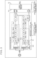
- FIG. 10 is a diagram depicting an example of the configuration of a photosynthesis gauging apparatus 10 of the first embodiment.
- the photosynthesis gauging apparatus 10 estimates (calculates) the quantum yield of the photosynthesis as the unknown parameter of the parameters relating to a transient model by applying a calculation algorithm in accordance with the transient model that presents the photosynthesis of a plant to measurement data of a transient response of the chlorophyll fluorescence obtained from the plant 1 to be measured.
- the photosynthesis gauging apparatus 10 includes a central control part 100, a light emitting part 101, a light emission control part 102, an optical filter 103, an optical sensor 104, a sampling part 105, a transient model storing part 106, a calculation algorithm storing part 107, a selector 108, a selector 109, a photosynthesis quantum yield computing part 110, and a result displaying part 111.
- the central control part 100 includes a circuit such as, for example, a CPU (Central Processing Unit) or an FPGA (Field Programmable Gate Array).
- the central control part 100 controls the operations of the components of the photosynthesis gauging apparatus 10. For example, the central control part 100 controls light emission control executed by the light emission control part 102, sampling executed by the sampling part 105, selection of the transient model executed by the selector 108, selection of the calculation algorithm executed by the selector 109, and displaying of the result executed by the result displaying part 111.
- a CPU Central Processing Unit
- FPGA Field Programmable Gate Array
- the light emitting part 101 is, for example, a light emitting apparatus that emits (radiates) a light beam by an LED (Light Emitting Diode).
- the light emitting part 101 emits, for example, light beams having three types of intensity in accordance with the control from the light emission control part 102.
- the light beams emitted from the light emitting part 101 are applied to the plant 1.
- the light emission control part 102 controls the light emission intensity and the light emission sequence of each of the light beams emitted from the light emitting part 101 in accordance with the control from the central control part 100.
- the optical filter 103 is a filter to separate the environmental light and the chlorophyll fluorescence from each other.
- a bandpass filter or a lowpass filter for the wavelength separating the excitation light beam (a visible light beam) and the chlorophyll fluorescence (having a wavelength of approximately 680 to approximately 750 nm) from each other is used.
- a bandpass filter may be used that has a narrow wavelength band and that selectively transmits the fluorescence of the sun dark line (such as, for example, oxygen (O 2 ), having the absorbance band of 687 nm).
- the optical sensor 104 is a one-dimensional or a two-dimensional sensor having the sensitivity for the wavelength of the chlorophyll fluorescence to measure (sense) the intensity of the chlorophyll fluorescence.
- the optical sensor 104 detects the light beam transmitted through the optical filter 103 using a sensing element and supplies a measurement signal (intensity value) of the chlorophyll fluorescence obtained as the result thereof to the sampling part 105.
- the one-dimensional sensing is aimed, for example, a sensing element having a photodiode mounted thereon is usable as the optical sensor 104.
- an image sensor including a sensing element that has plural pixels two-dimensionally arranged therein in repeated patterns such as a CMOS (Complementary Meatal-Oxide Semiconductor) or a CCD (Charge Coupled Device), is usable as the optical sensor 104.
- CMOS Complementary Meatal-Oxide Semiconductor
- CCD Charge Coupled Device
- the "sensing” means measuring the plant 1 to be measured. Moreover, the “sensing” also includes the meaning of shooting the plant 1 to be measured.
- the sampling part 105 executes sampling for the measurement signal (intensity value) of the chlorophyll fluorescence from the optical sensor 104 and thereby converts the measurement signal of the chlorophyll fluorescence from the analog signal to a digital signal in order of elapse of time.
- the measurement data of the chlorophyll fluorescence obtained as the result of the sampling is supplied to the photosynthesis quantum yield computing part 110.
- the measurement data obtained by the sampling is handled as one-dimensional or two-dimensional time-series measurement data of the chlorophyll fluorescence.
- the measurement data can be established as any one of various formats of data such as, for example, image data in addition to the numerical data.
- the transient model storing part 106 stores therein one or plural transient model(s).
- the selector 108 selects a transient model to be used from the transient models stored in the transient model storing part 106 and supplies the transient model to be used to the photosynthesis quantum yield computing part 110.
- the calculation algorithm storing part 107 stores therein one or plural photosynthesis quantum yield calculation algorithm(s).
- the selector 109 selects a photosynthesis quantum yield calculation algorithm to be used from the photosynthesis quantum yield calculation algorithm(s) stored in the calculation algorithm storing part 107 and supplies the photosynthesis quantum yield calculation algorithm to be used to the photosynthesis quantum yield computing part 110.
- transient model storing part 106 and the calculation algorithm storing part 107 are constituted as a storage part 130 that includes a semiconductor memory (such as, for example, a RAM (Random Access Memory)) or the like.
- a semiconductor memory such as, for example, a RAM (Random Access Memory)
- the photosynthesis quantum yield computing part 110 calculates the quantum yield of the photosynthesis that is the unknown parameter of the parameters relating to the transient model by applying the photosynthesis quantum yield calculation algorithm in accordance with the transient model that presents the photosynthesis of a plant, to the measurement data of the transient response of the chlorophyll fluorescence of the plant 1.
- the photosynthesis quantum yield computing part 110 supplies the calculated quantum yield of the photosynthesis to the result displaying part 111.
- At least one of the maximal quantum yield (Fv/Fm)of the electron transfer system of the photosynthesis or the quantum yield ( ⁇ PSII) of the electron transfer system of the photosynthesis is calculated as the quantum yield of the photosynthesis.
- the result displaying part 111 includes a display such as, for example, an LCD (Liquid Crystal Display) or an OELD (Organic Electroluminescence Display).
- the result displaying part 111 displays the data (such as, for example, numerical data or image data) relating to the result of the computation for the quantum yield (Fv/Fm and/or ⁇ PSII) of the photosynthesis supplied from the photosynthesis quantum yield computing part 110.
- all or some of the functions of the sampling part 105, the selector 108, the selector 109, and the photosynthesis quantum yield computing part 110 can be adapted to be realized by, for example, programs (software) executed by the central control part 100 constituted as a CPU.
- a of FIG. 11 depicts the intensity of the light beam emitted from the light emitting part 101 and B of FIG. 11 depicts the intensity of the chlorophyll fluorescence of the plant 1 caused by controlling the light beam emitted from the light emitting part 101.
- the growing light beams are the light beams each having the intensity used when a plant is grown, and the intensities thereof are each approximately 100 [ ⁇ mol/m 2 /s] as the minimal value.
- the intensity of the second growing light beam is higher than that of the first growing light beam.
- the gauging is generally started after the plant 1 is darkacclimatized by placing the plant 1 in a dark state for a proper time period (such as, for example, 30 minutes or longer).
- a proper time period such as, for example, 30 minutes or longer.
- the level of the intensity of the chlorophyll fluorescence substantially does not vary in the second section while the level thereof is increased immediately after the second growing light beam is applied in the third section.
- the photosynthesis gauging apparatus 10 gauges the sampling part 105 to execute the sampling of the chlorophyll fluorescence at a time ts0 in the second section (or the border between the second section and the third section) and at each of times (a time ts1, a time ts2, and a time ts3) when the level of the intensity of the chlorophyll fluorescence is increased immediately after the second growing light beam is applied in the third section.
- the time ts1, the time ts2, the time ts3 are set to satisfy the conditions that the time ts0 is the starting point, that the 250 microseconds is the minimal value, and that 500 milliseconds is the maximal value.
- the photosynthesis quantum yield computing part 110 can thereafter calculate ⁇ PSII on the basis of the measurement data of the transient response of the chlorophyll fluorescence of the plant 1 (the values of the intensity level of the chlorophyll fluorescence). In sum, in this case, the quantum yield ( ⁇ PSII) obtained when the light beam having a specific intensity is applied for the photosynthesis to be performed can be determined.
- the measurement data of the transient response of the chlorophyll fluorescence of the plant 1 is caused to be obtained by increasing (enhancing) the light emission intensity of the light beam in the light emission sequence of FIG. 11 while the point is that it is sufficient that the light emission intensity of the light beam is varied, and the measurement data of the transient response can also be obtained by, for example, reducing (weakening) the light emission intensity of the light beam.
- the central control part 100 controls the light emission control part 102 to cause the measurement light beam to be applied from the light emitting part 101 to the plant 1.
- the measurement signal of the chlorophyll fluorescence from the plant 1 to which the measurement light beam is applied is thereby input from the optical sensor 104 into the sampling part 105.
- the central control part 100 controls the sampling part 105 to cause the sampling to be executed for the measurement signal of the chlorophyll fluorescence from the optical sensor 104.
- the measurement signal of the chlorophyll fluorescence of the plant 1 to which the measurement light beam is applied is thereby converted into the digital signal and the measurement data obtained as the result thereof is output to the photosynthesis quantum yield computing part 110.
- the central control part 100 controls the components to cause the first growing light beam to be applied to the plant 1 and to cause the sampling for the chlorophyll fluorescence to be executed at the timings of the time t1, the time t2, and the time t3 in FIG. 11 .
- the central control part 100 controls the light emission control part 102 to cause the first growing light beam from the light emitting part 101 to be applied to the plant 1.
- the measurement signal of the chlorophyll fluorescence from the plant 1 to which the first growing light beam is applied is thereby input from the optical sensor 104 into the sampling part 105.
- the central control part 100 controls the sampling part 105 to cause the sampling to be executed for the measurement signal of the chlorophyll fluorescence from the optical sensor 104.
- the measurement signal of the chlorophyll fluorescence of the plant 1 to which the first growing light beam is applied is thereby converted into the digital signal and the measurement data obtained as the result thereof is output to the photosynthesis quantum yield computing part 110.
- the sampling is also executed similar to that at the timing of the time t1.
- the central control part 100 controls the light emission control part 102 to cause the application of the first growing light beam from the light emitting part 101 to be continued.
- the application of the first growing light beam to the plant 1 is started in the process of step S102 while the application of the first growing light beam to the plant 1 is also continued in the process of step S103.
- the central control part 100 controls the sampling part 105 to cause the sampling for the measurement signal of the chlorophyll fluorescence from the optical sensor 104, to be executed.
- the measurement signal of the chlorophyll fluorescence of the plant 1 to which the first growing light beam is applied is thereby converted into the digital signal and the measurement data obtained as the result thereof is output to the photosynthesis quantum yield computing part 110.
- the central control part 100 controls the components to cause the second growing light beam to be applied to the plant 1 and to cause the sampling for the chlorophyll fluorescence to be executed at the timings of the time ts1, the time ts2, and the time ts3 in FIG. 11 .
- the central control part 100 controls the light emission control part 102 to cause the second growing light beam from the light emitting part 101 to be applied to the plant 1.
- the measurement signal of the chlorophyll fluorescence from the plant 1 to which the second growing light beam is applied is thereby input from the optical sensor 104 into the sampling part 105.
- the central control part 100 controls the sampling part 105 to execute the sampling for the measurement signal of the chlorophyll fluorescence from the optical sensor 104.
- the measurement signal of the chlorophyll fluorescence of the plant 1 to which the second growing light beam is applied is thereby converted into the digital signal and the measurement data obtained as the result thereof is output to the photosynthesis quantum yield computing part 110.
- the sampling is also executed similar to that at the timing of the time ts1.
- the central control part 100 controls the selector 108 to cause the transient model to be used for the gauging of the quantum yield of the photosynthesis to be selected from the one or the plural transient model(s) stored in the transient model storing part 106.
- the transient models such as, for example, a puddle model, a lake model, and a connected unit model are stored therein
- the puddle model (a transient model thereof) can be selected.
- the central control part 100 controls the selector 109 to cause the photosynthesis quantum yield calculation algorithm that corresponds to the transient model selected in the process of step S106, to be selected from the one or the plural photosynthesis quantum yield calculation algorithm(s) stored in the calculation algorithm storing part 107.
- the photosynthesis quantum yield calculation algorithm for the puddle model can be selected.
- the central control part 100 controls the photosynthesis quantum yield computing part 110 to cause the quantum yield of the photosynthesis to be calculated by applying the photosynthesis quantum yield calculation algorithm obtained in the process of step S107 to the measurement data of the transient response obtained in the processes of steps S101 to S105.
- the central control part 100 controls the result displaying part 111 to cause the computation result of the process of step S108 to be displayed on the result displaying part 111.
- the data relating to the computation result of the quantum yields (Fv/Fm and ⁇ P3II) of the photosynthesis is thereby displayed on the result displaying part 111.
- a plant-physiological model such as, for example, a puddle model, a lake model, or a connected unit model is usable as the transient model.
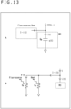
- a of FIG. 13 depicts an example of the configuration of the model of the reaction center (RC) that corresponds to the puddle model.
- the puddle model can be represented by an equivalent circuit according to which the reaction center (RC) preferentially obtains the photons that are input therein (converts the photons into electrons) and the photons unable to be obtained by the reaction center (RC) flow into the side of the chlorophyll fluorescence and the heat.
- the reaction center (RC) includes plural modules (Q A , Q B , PQ, and the like).
- the reaction center (RC) is represented as a capacitor and this capacitor accumulates the current (i(t)) corresponding to the photons preferentially input thereinto as a charge (q(t)). More over, in the case where the maximal charge storage amount of the capacitor of the reaction center (RC) is exceeded by the flowing-in of the current that corresponds to the photons to the side of the reaction center (RC), the current (I-i(t)) corresponding to the photons flows into the side of the fluorescence and the heat.
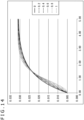
- the four waveforms denoted by "0.2,” “0.4,” “0.6,” and “0.8” each correspond to the connected unit model.
- the energy transfer among the reaction centers (RCs) occurs at a fixed probability and the waveform of the chlorophyll response becomes a shape formed by combining the shape of the natural logarithm and the shape of a sigmoid function with each other.
- the waveform denoted by "1" corresponds to the lake model.
- the energy transfer among the reaction centers (RCs) occurs at the probability of 100% and the waveform of the chlorophyll response becomes the shape of the sigmoid function.
- the modeling can be executed for the puddle model assuming that the energy unable to be transferred to the reaction center (RC) is released in the form of the chlorophyll fluorescence and heat.
- the magnitude (PPFD value) of the input light beam input into the side of the chlorophyll fluorescence and the heat is represented by "I-i(t)” and the degrees of the energy absorbed as the chlorophyll fluorescence and the heat are respectively represented by "G F " and "G H ,” the fact is depicted that I-i(t) corresponds to a current, and G F and G H each correspond to conductance, that are connected in parallel to each other.
- F 0 and F m I ⁇ G F G F + G H
- the energy is divided being influenced by the parameters of the three output elements as parallel circuits among each other.
- an element referred to as "extraction time period of the excited energy” is present, and the “extraction time period” of the reaction center (RC) is quicker than those of the chlorophyll fluorescence and the heat.
- the energy is therefore preferentially distributed to the reaction center (RC) because of this temporal priority.
- the above described puddle model handles the rest of the energy, that is unable to be received by the reaction center (RC) as the energy to be distributed to the chlorophyll fluorescence and the heat each as an independent circuit.
- the puddle model is used as the transient model
- the lake model or the connected unit model may be used.
- any other plant-physiological model can be used as the transient model, such as, for example, an excess model that is the model for the case where the leaves of a plant are heavily damaged.
- these models are each generally non-linear, not a parameter identification algorithm using the analytical solution described in the embodiments of the present technique but a parameter identification algorithm using a regression analysis may be used.
- Equation (14) can be represented as in Equation (15) below.
- Equation (17) the time constant (k) can be determined by applying first-order differentiation and second-order differentiation to Equation (17) and taking the ratios of the values obtained as the result thereof.
- first-order differential and the second-order differential in this case are respectively represented by Equation (18) and Equation (19) below.
- Equation (20) can be determined from the pieces of measurement data of three points.
- the measurement data is represented by f(t)
- the pieces of measurement data at the time t1, the time t2, and the time t3 are a, b, and c
- the slope of the graph between the times t1 and t2 are represented as below.
- Equation (21) Equation (21) below.
- the time constant (k) can be determined.
- the photosynthesis gauging apparatus 10 executes the processes from the measurement of the measurement data of the transient response of the chlorophyll fluorescence of the plant 1 to the application of the photosynthesis quantum yield calculation algorithm for the puddle model by executing the processes of steps S151 to S154 in FIG. 16 .
- the light emission sequence presented at step S151 corresponds to the first section and a partial section of the second section in the light emission sequence in FIG. 11 described above.
- the photosynthesis quantum yield computing part 110 next applies the measurement data of the transient response (the pieces of measurement data for the three points) from the sampling part 105, to Equation (21) using the approach depicted in FIG. 15 and can thereby calculate the time constant (k) (S152).
- the photosynthesis quantum yield computing part 110 next applies the measurement data of the transient response from the sampling part 105 to Equation (14) and can thereby calculate rFv (S153).
- the photosynthesis quantum yield computing part 110 applies the time constant (k) obtained in the process of step S152 and rFv obtained in the process of step S153 to Equation (22) below as the photosynthesis quantum yield calculation algorithm for the puddle model and can thereby calculate P M (S154). It is as described above that P M determined in this manner corresponds to Fv/Fm as the quantum yield of the photosynthesis.
- Fv/Fm as the quantum yield of the photosynthesis can be determined.
- ⁇ PSII is calculated as the quantum yield of the photosynthesis
- the calculation algorithm for ⁇ PSII is used.
- the time constant (k) also needs to be determined in the case where ⁇ PSII is calculated while the time constant (k) can be calculated using the approach depicted in FIG. 15 described above.
- the photosynthesis gauging apparatus 10 executes the processes of steps S171 to S174 in FIG. 17 and thereby executes the processes from the measurement of the measurement data of the transient response of the chlorophyll fluorescence of the plant 1 to the application of the photosynthesis quantum yield calculation algorithm for the puddle model.
- ⁇ PSII is calculated as the quantum yield of the photosynthesis and the light emission sequence presented at step S171 therefore corresponds to the second section and a partial section of the third section in the light emission sequence of FIG. 11 described above.
- the photosynthesis quantum yield computing part 110 can next calculate the time constant (k) on the basis of the measurement data of the transient response (the pieces of measurement data for the three points) from the sampling part 105 using the approach depicted in FIG. 15 described above (S172).
- the photosynthesis quantum yield computing part 110 can next calculate rFv on the basis of the measurement data of the transient response from the sampling part 105 (S173).
- the photosynthesis quantum yield computing part 110 thereafter applies the time constant (k) obtained in the process of step S172 and rFv obtained in the process of step S173 to Equation (24) below as the photosynthesis quantum yield calculation algorithm for the puddle model and can thereby calculate ⁇ PSII (S174).
- ⁇ PSII can be determined as the quantum yield of the photosynthesis.
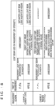
- the measurement data of the transient response of the chlorophyll fluorescence is obtained by applying the measurement light beam and the growing light beam (steady light beam) to the plant 1, and the quantum yield of the photosynthesis can be calculated even without the saturated light beam by processing the measurement data as the input data in accordance with the photosynthesis quantum yield calculation algorithm in accordance with the transient model such as the puddle model.
- the two types of light beam of the measurement light beam and the saturated light beam are used.
- the intensity of the measurement light beam used in this case is set to be approximately 10 [ ⁇ mol/m 2 /s].
- the intensity of the saturated light beam is set to be 2,000 [ ⁇ mol/m 2 /s] or higher.
- the saturated light beam is also referred to as "saturated pulse light beam.”
- the steady light beam is unnecessary.
- the two types of light beam of the steady light beam and the saturated light beam are used.
- the intensity of the steady light beam used in this gauging is the intensity to be used to grow the plant 1 and is set to be approximately 100 [ ⁇ mol/m 2 /s] as the minimal value.
- the intensity of the saturated light beam is also set to be 2,000 [ ⁇ mol/m 2 /s] or higher.
- the measurement light beam is unnecessary.
- the two types of light beam of the measurement light beam and the growing light beam (first growing light beam) are used.
- the intensity of the measurement light beam used in this gauging is set to be approximately 10 [ ⁇ mol/m 2 /s].
- the intensity of the first growing light beam is the intensity to be used to grow the plant 1 and is set to be approximately 100 [ ⁇ mol/m 2 /s] as the minimal value.
- the first growing light beam is also referred to as "first steady light beam.”
- the saturated light beam is unnecessary.
- the two types of growing light beam (the first growing light beam and the second growing light beam) are used.
- the intensities of the first growing light beam and the second growing light beam used in this gauging are the intensities to be used to grow the plant 1 and are each set to be approximately 100 [ ⁇ mol/m 2 /s] as the minimal value.
- the intensity of the second growing light beam is set to be higher than the intensity of the first growing light beam (the first growing light beam ⁇ the second growing light beam).
- the second growing light beam is also referred to as "second steady light beam.”
- the measurement light beam and the saturated light beam are unnecessary.
- the saturated light beam is necessary for both of the gauging of Fv/Fm and the gauging of ⁇ P3II.
- the saturated light beam is unnecessary for both of the gauging of Fv/Fm and the gauging of ⁇ PSII.
- a low output per unit area of the light emitting apparatus (light emitting part) necessary for the measurement is therefore sufficient compared to that of the photosynthesis gauging apparatus 90 ( FIG. 5 ) employing the technique in the current state (pulse-modulated fluorescence measurement), and the measurement in wider range is thereby enabled.
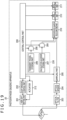
- FIG. 19 is a diagram depicting an example of the configuration of a photosynthesis gauging apparatus 20 of the second embodiment.
- the photosynthesis gauging apparatus 20 includes a central control part 200, a laser light emitting part 201, a light emission control part 202, an optical filter 203, an optical sensor 204, a sampling part 205, a transient model storing part 206, a calculation algorithm storing part 207, a selector 208, a selector 209, a photosynthesis quantum yield computing part 210, a result displaying part 211, an actuator 212, and an image synthesizing part 213.
- the transient model storing part 206 and the calculation algorithm storing part 207 are constituted as a storage part 230 that includes a semiconductor memory or the like.
- the photosynthesis gauging apparatus 20 in FIG. 19 differs therefrom in the point that the laser light emitting part 201 is disposed therein instead of the light emitting part 101, and the actuator 212 and the image synthesizing part 213 are newly disposed therein.
- the configuration except the above of the photosynthesis gauging apparatus 20 is basically similar to the configuration of the photosynthesis gauging apparatus 10, and will therefore properly not again be described.
- the laser light emitting part 201 emits (radiates) laser light beams of, for example, three levels of intensity (the measurement light beam, the first growing light beam, and the second growing light beam).
- the actuator 212 has a function of scanning a predetermined area of the plant 1 to be measured, using the laser light beams emitted from the laser light emitting part 201.
- the chlorophyll fluorescence of the plant 1 to which the laser light beam is applied is detected by the optical sensor 204 constituted as a two-dimensional sensor through the optical filter 203. Sampling of the measurement signal (intensity value) of the chlorophyll fluorescence from the optical sensor 204 is thereafter executed by the sampling part 205.
- the photosynthesis quantum yield computing part 210 calculates the quantum yields (Fv/Fm and ⁇ P3II) of the photosynthesis that each are the unknown parameter of the parameters relating to the transient model by applying the photosynthesis quantum yield calculation algorithm in accordance with the transient model that presents the photosynthesis of a plant, to the measurement data of the transient response of the chlorophyll fluorescence of the plant 1.
- the quantum yield of the photosynthesis is calculated for each scanning by the laser light beam and is supplied to the image synthesizing part 213.
- the image synthesizing part 213 synthesizes the quantum yield of the photosynthesis obtained for each scanning by the laser light beam to generate one image.
- the image generated by the image synthesizing part 213 is displayed on the result displaying part 211.
- the photosynthesis gauging apparatus 20 is configured as above.
- the photosynthesis gauging process executed by the photosynthesis gauging apparatus 20 in FIG. 19 is basically similar to the photosynthesis gauging process ( FIG. 12 ) described above but differs therefrom in the point that the light beam applied to the plant 1 is the laser light beam.
- the laser light beam from the laser light emitting part 201 ( FIG. 19 ) is used instead of the light beam from the light emitting part 101 ( FIG. 10 ) by an LED or the like when the sampling is executed in the processes of steps S101 to S105 in FIG. 12 .
- the measurement data of the transient response of the chlorophyll fluorescence is obtained by executing the scanning by the laser light beam for the plant 1, and the quantum yield of the photosynthesis can be calculated even without the saturated light beam by processing the measurement data as the input data in accordance with the photosynthesis quantum yield calculation algorithm in accordance with the transient model such as the puddle model.
- JP2006/504956A is present as a technique of gauging the quantum yield of the photosynthesis using a laser light beam.
- an apparatus is disclosed that executes two-dimensional gauging for the quantum yield of the photosynthesis by moving a beam of the laser light to thereby scan the chlorophyll fluorescence using a camera for each dot.
- a plant material is scanned using a laser light beam of approximately 1 Hz to approximately 10 kHz (that is, one second to 0.1 millisecond per dot) referred to as "Ffast gauging” and is thereafter scanned using a laser light beam of approximately 0.01 to approximately 1 Hz (that is, 100 seconds to one second per dot) referred to as “Fslow gauging.”
- the quantum yield of the photosynthetic activity is thereafter computed in accordance with Equation (25) below.
- IQP Fslow ⁇ Ffast / Fslow
- the gauging for one dot needs one second or longer and a long time is therefore necessary for the gauging in the case where the resolution is tried to be improved.
- 278 hours are necessary while, in the case where the present technique is used, when two-dimensionally arranged sensing elements are used as the optical sensor 104, points corresponding to one image can be gauged at one time and the gauging can be finished within 500 milliseconds as the maximal value.
- the photosynthesis gauging apparatus 30 ( FIG. 19 ) of the second embodiment also uses the laser light beam as the light beam to be applied to the plant 1 but, compared to the technique disclosed in the above literature, can execute the measurement without using the saturated light beam.
- a low output per unit area of the laser light emitting part 201 is therefore sufficient and the safety is therefore improved for open-air measurement and, in addition, the time period necessary for the measurement can be reduced.
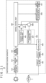
- FIG. 20 is a diagram depicting an example of the configuration of the photosynthesis gauging apparatus 30 of the third embodiment.
- the photosynthesis gauging apparatus 30 includes a central control part 300, a light emission control part 302, an optical filter 303, an optical sensor 304, a sampling part 305, a transient model storing part 306, a calculation algorithm storing part 307, a selector 308, a selector 309, a photosynthesis quantum yield computing part 310, a result displaying part 311, and an interface 312.
- the transient model storing part 306 and the calculation algorithm storing part 307 are constituted as a storage part 330 that includes a semiconductor memory or the like.
- the photosynthesis gauging apparatus 30 in FIG. 20 differs therefrom in the point that the interface 312 to connect to an external apparatus is disposed therein instead of the light emitting part 101.
- the configuration other than the above is basically similar to the configuration of the photosynthesis gauging apparatus 10 and will therefore properly not again be described.
- the interface 312 includes an input and output interface circuit and the like, and is adapted to be connectable to an external plant growing light emitting apparatus 31.
- the plant growing light emitting apparatus 31 is an apparatus that emits a light beam to grow a plant such as, for example, a light beam by an LED.
- the light beam emitted by an LED or the like is applied by the plant growing light emitting apparatus 31 for a specific time period and, thereby, the light beam having the wavelength necessary for the photosynthesis can efficiently be applied and the growth of the plant can be advanced.
- the light emission control part 302 controls the light beam emitted from the plant growing light emitting apparatus 31, through the interface 312. In accordance with the control from the light emission control part 302, the plant growing light emitting apparatus 31 emits (radiates) light beams having, for example, three levels of intensity (the measurement light beam, the first growing light beam, and the second growing light beam).
- the chlorophyll fluorescence of the plant to which the light beam from the plant growing light emitting apparatus 31 is applied is detected by the optical sensor 304 through the optical filter 303. Sampling of the measurement signal (intensity value) of the chlorophyll fluorescence from the optical sensor 304 is thereafter executed by the sampling part 305.
- the photosynthesis quantum yield computing part 310 calculates the quantum yields (Fv/Fm and ⁇ P3II) of the photosynthesis that each are the unknown parameter of the parameters relating to the transient model by applying the photosynthesis quantum yield calculation algorithm in accordance with the transient model that presents the photosynthesis of a plant, to the measurement data of the transient response of the chlorophyll fluorescence of the plant 1.
- the result of the computation by the photosynthesis quantum yield computing part 310 is displayed on the result displaying part 311.
- the photosynthesis gauging apparatus 30 is configured as above.
- the photosynthesis gauging process executed by the photosynthesis gauging apparatus 30 in FIG. 20 is basically similar to the photosynthesis gauging process ( FIG. 12 ) described above but differs therefrom in the point that the light beam to be applied to the plant 1 is applied by the external plant growing light emitting apparatus 31.
- a light beam by an LED or the like from the plant growing light emitting apparatus 31 ( FIG. 20 ) is used instead of the light beam by an LED or the like from the light emitting part 101 ( FIG. 10 ) when the sampling is executed in the processes of steps S101 to S105 in FIG. 12 .
- the measurement data of the transient response of the chlorophyll fluorescence is obtained by applying the light beam from the external plant growing light emitting apparatus 31 to the plant 1, and the quantum yield of the photosynthesis can be calculated even without the saturated light beam by processing the measurement data as the input data in accordance with the photosynthesis quantum yield calculation algorithm in accordance with the transient model such as the puddle model.
- the quantum yield of the photosynthesis can be determined on the side of the photosynthesis gauging apparatus 30 without preparing any special light source to execute the gauging for the photosynthesis.
- the photosynthesis gauging apparatus 40 includes a central control part 400, an optical filter 403, an optical sensor 404, a sampling part 405, a transient model storing part 406, a calculation algorithm storing part 407, a selector 408, a selector 409, a photosynthesis quantum yield computing part 410, a result displaying part 411, an environmental light sensor 412, a sampling part 413, and an optimal variation detecting part 414.
- the transient model storing part 406 and the calculation algorithm storing part 407 are constituted as a storage part 430 that includes a semiconductor memory or the like.
- the photosynthesis gauging apparatus 40 in FIG. 21 differs therefrom in the point that the environmental light sensor 412, the sampling part 413, and the optimal variation detecting part 414 are disposed therein instead of the light emitting part 101 and the light emission control part 102.
- the configuration other than the above is basically similar to the configuration of the photosynthesis gauging apparatus 10 and will therefore properly not again be described.
- the environmental light sensor 412 is a sensor to measure the intensity of the environmental light such as the sunlight.
- the environmental light sensor 412 supplies a measurement signal corresponding to the intensity of the environmental light to the sampling part 413.
- the sampling part 413 converts the measurement signal of the environmental light from an analog signal to a digital signal in order of elapse of time by executing the sampling for the measurement signal (intensity value) of the environmental light from the environmental light sensor 412.
- the measurement data of the environmental light obtained as the result of the sampling is supplied to the optimal variation detecting part 414.
- the optimal variation detecting part 414 detects an abrupt variation necessary for executing the photosynthesis gauging for the plant 1, of the variations of the intensity of the environmental light on the basis of the measurement data of the environmental light from the sampling part 413, and supplies the result of the detection to the central control part 400.
- the intensity variation of the environmental light corresponding to the variation of the light emission intensity to the first growing light beam for the second section is detected from the measurement light beam for the first section.
- the intensity variation of the environmental light corresponding to the variation of the light emission intensity to the second growing light beam for the third section is detected from the first growing light beam for the second section in the light emission sequence of FIG. 11 .
- the sampling of the chlorophyll fluorescence is caused to be executed at predetermined timings that correspond to the timings of the time t0, the time t1, the time t2, and the time t3 in FIG. 11 by detecting the intensity variation of the environmental light that corresponds to the variation of the light emission intensity in the light emission sequence depicted in FIG. 11 .
- the sampling of the chlorophyll fluorescence is caused to be executed at predetermined timings that correspond to the timings of the time ts0, the time ts1, the time ts2, and the time ts3 in FIG. 11 by detecting the intensity variation of the environmental light that corresponds to the variation of the light emission intensity in the light emission sequence depicted in FIG. 11 .
- the photosynthesis quantum yield computing part 410 calculates the quantum yields (Fv/Fm and ⁇ P3II) of the photosynthesis that each are the unknown parameter of the parameters relating to the transient model by applying the photosynthesis quantum yield calculation algorithm in accordance with the transient model that presents the photosynthesis of a plant, to the measurement data of the transient response of the chlorophyll fluorescence of the plant 1.
- the result of the computation by the photosynthesis quantum yield computing part 410 is displayed on the result displaying part 411.
- the photosynthesis gauging process executed by the photosynthesis gauging apparatus 40 in FIG. 21 is basically similar to the photosynthesis gauging process ( FIG. 12 ) described above but differs therefrom in the point that the light beam to be applied to the plant 1 is only the environmental light such as the sunlight and the point that the timings of the sampling of the chlorophyll fluorescence of the plant 1 are determined in accordance with the timings of the intensity variation of the environmental light.
- the environmental light such as the sunlight is used instead of the light beam by an LED or the like from the light emitting part 101 ( FIG. 10 ).
- the timings of the sampling of the chlorophyll fluorescence such as the times t0 to t3 and the times ts0 to ts3 are determined in accordance not with the variation of the light emission intensity of the light beam emitted from the light emitting part 101 ( FIG. 10 ) but with the timings of the intensity variation of the environmental light such as the sunlight.
- the measurement data of the transient response of the chlorophyll fluorescence sampled at the timings in accordance with the intensity variation of the environmental light is obtained by setting only the environmental light such as the sunlight to be applied to the plant 1, and the quantum yield of the photosynthesis can be calculated by processing the measurement data as the input data in accordance with the photosynthesis quantum yield calculation algorithm in accordance with the transient model such as the puddle model.
- the above described photosynthesis gauging apparatus 10 ( FIG. 10 ) or the like causes the light beam applied to the plant 1 to instantaneously be enhanced by controlling the intensity and the timings of the light beam applied to the plant 1, and executes the sampling at these timings.
- the photosynthesis gauging apparatus 40 of the fourth non-claimed example is adapted to detect the timings of the intensity variation and to execute sampling at the timings in accordance with the result of the detection.
- the photosynthesis gauging apparatus 40 of the fourth non-claimed example continuously measures the variation of the environmental light such as the sunlight using the environmental light sensor 412, selects the time when the convenient intensity variation of the environmental light happens to occur, and executes the gauging for the photosynthesis.
- the quantum yield of the photosynthesis is calculated using the intensity variation of the environmental light such as the sunlight without using not only the saturated light beam but also even the measurement light beam and the steady light beam (growing light beam).
- the intensity variation of the environmental light such as the sunlight, or the like is used, the light emission sequence depicted in FIG. 11 is not essential.
- the approach of measuring the intensity of the environmental light using the environmental light sensor 412 has been described as an approach of measuring the variation of the intensity of the environmental light in the fourth non-claimed example while, for example, the fourth non-claimed example may be adapted to measure the variation of the intensity of the environmental light using another approach such as, for example, an approach of measuring the illuminance on the leaf surface of the plant 1.
- FIG. 22 is a diagram depicting an example of the configuration of an information processing apparatus 50 of the fifth non-claimed example.
- the information processing apparatus 50 includes a central control part 500, a transient model storing part 506, a calculation algorithm storing part 507, a selector 508, a selector 509, a photosynthesis quantum yield computing part 510, and a result displaying part 511.
- the transient model storing part 506 and the calculation algorithm storing part 507 are constituted as a storage part 530 that includes a semiconductor memory or the like.
- the information processing apparatus 50 in FIG. 22 differs therefrom in the point that an interface 512 is disposed therein instead of the light emitting part 101 to the sampling part 105.
- the configuration except the above is set to basically be similar to the configuration of the photosynthesis gauging apparatus 10 and will therefore properly not again be described.
- the external storage 51 is, for example, a large-capacity recording apparatus such as a hard disc or a semiconductor memory.
- the external storage 51 accumulates therein files of measurement data of the transient response of the chlorophyll fluorescence of the plant 1 (hereinafter, referred to as "transient response measurement files").
- the external storage 51 provides the transient response measurement files accumulated therein to the information processing apparatus 50 in response to a request or the like from the information processing apparatus 50.
- the transient response measurement files from the external storage 51 are supplied to the photosynthesis quantum yield computing part 510 through the interface 512.
- the external chlorophyll fluorescence gauging apparatus 52 is an apparatus that gauges (measures) the chlorophyll fluorescence of the plant 1.
- the external chlorophyll fluorescence gauging apparatus 52 has the functions that correspond to those of the central control part 100, the light emitting part 101, the light emission control part 102, the optical filter 103, the optical sensor 104, and the sampling part 105 depicted in FIG. 10 , and can execute the sampling of the chlorophyll fluorescence of the plant 1 to which the measurement light beam or the growing light beams are applied.
- the external chlorophyll fluorescence gauging apparatus 52 In response to a request or the like from the information processing apparatus 50, the external chlorophyll fluorescence gauging apparatus 52 provides the measurement data of the transient response of the chlorophyll fluorescence of the plant 1 to the information processing apparatus 50 through the network 53. In the information processing apparatus 50, the measurement data of the transient response from the external chlorophyll fluorescence gauging apparatus 52 is supplied to the photosynthesis quantum yield computing part 510 through the interface 512.
- the files of the measurement data may be adapted to be provided instead of the measurement data of the transient response.
- an information processing apparatus such as a server connected to the network 53 such as the Internet may be adapted to provide the measurement data of the transient response or the transient response measurement files through the network 53.
- the transient response measurement files or the measurement data of the transient response are/is provided from the external storage 51 or the external chlorophyll fluorescence gauging apparatus 52 to the photosynthesis quantum yield computing part 510.
- the transient response measurement files include the measurement data of the transient response.
- the photosynthesis quantum yield computing part 510 calculates the quantum yields (Fv/Fm and ⁇ P3II) of the photosynthesis that each are the unknown parameter of the parameters relating to the transient model by applying the photosynthesis quantum yield calculation algorithm in accordance with the transient model that presents the photosynthesis of a plant, to the externally provided measurement data of the transient response.
- the result of the computation by the photosynthesis quantum yield computing part 510 is displayed on the result displaying part 511.
- the information processing apparatus 50 is configured as above.
- steps S101 to S105 in the pre-stage are executed by the external chlorophyll fluorescence gauging apparatus 52, or the transient response measurement files obtained in the processes of steps S101 to S105 in the pre-stage are stored in the external storage 51.
- the information processing apparatus 50 thereafter executes the processes of steps S106 to S109 in the post-stage using the measurement data of the transient response obtained from the external storage 51 or the external chlorophyll fluorescence gauging apparatus 52.
- the quantum yield of the photosynthesis can be calculated by obtaining the externally provided measurement data of the transient response, and processing the measurement data as the input data in accordance with the photosynthesis quantum yield calculation algorithm in accordance with the transient model such as the puddle model.
- FIG. 23 depicts as examples a fixed-point measuring apparatus 60A executing fixed-point observation and a moving measuring apparatus 60B executing moving observation, as specific examples of the measuring apparatus executing the measurement for the plant 1 to be measured, in the first embodiment to the fifth non-claimed example described above.
- the fixed-point measuring apparatus 60A depicted in A of FIG. 23 is fixed at a position at which the fixed-point measuring apparatus 60A can measure (sense) the plant 1 to be measured (such as, for example, a plant in a farm field), by fixed legs 61A and transmits the measurement data of the transient response of the chlorophyll fluorescence of the plant 1 measured there to the information processing apparatus 50 ( FIG. 22 ) using, for example, wireless communication or the like.
- the information processing apparatus 50 can determine the quantum yield of the photosynthesis of the plant 1 that is fixed-point-observed by the fixed-point measuring apparatus 60A by processing the measurement data of the transient response transmitted from the fixed-point measuring apparatus 60A.
- the moving measuring apparatus 60B depicted in B of FIG. 23 is, for example, an unmanned aerial vehicle (UAV), flies by the rotation of its propeller-like rotor blades 61B, and measures (aerially photographs) the plant 1 to be measured (such as, for example, a plant in a farm field) from the air over.
- the moving measuring apparatus 60B transmits the measurement data of the transient response of the chlorophyll fluorescence of the plant 1 measured there to, for example, the information processing apparatus 50 ( FIG. 22 ) using, for example, wireless communication or the like.
- the information processing apparatus 50 can determine the quantum yield of the photosynthesis of the plant 1 moving-observed by the moving measuring apparatus 60B by processing the measurement data of the transient response transmitted from the moving measuring apparatus 60B.
- the moving measuring apparatus 60B may be adapted to autonomously fly using position information such as that by the GPS (Global Positioning System) by, for example, storing the flight route in advance as coordinate data.
- GPS Global Positioning System
- the present technique is characterized in that the unknown parameter of the parameters relating to a transient model is estimated (calculated) by applying the calculation algorithm in accordance with the transient model to the measurement data of the transient response obtained from the target to be measured as the input, and this principle is applicable to all the living bodies.
- the unknown parameter of the parameters relating to a transient model can therefore be calculated by applying the calculation algorithm in accordance with the transient model presenting the functions that the living body as the target has, to the measurement data of the transient response obtained from the living body to be measured as the input.
- the series of processes described above can be executed by the hardware and can also be executed by software.
- the programs constituting the software are installed in a computer.
- FIG. 24 is a diagram depicting an example of the configuration of the hardware of the computer that executes the series of processes described above using the programs.
- a CPU Central Processing Unit
- ROM Read Only Memory
- RAM Random Access Memory
- An input and output interface 1005 is further connected to the bus 1004.
- An input part 1006, an output part 1007, a recording part 1008, a communicating part 1009, and a drive 1010 are connected to the input and output interface 1005.
- the input part 1006 includes a keyboard, a mouse, a microphone, and the like.
- the output part 1007 includes a display, a speaker, and the like.
- the recording part 1008 includes a hard disc, a non-volatile memory, or the like.
- the communicating part 1009 includes a network interface and the like.
- the drive 1010 drives a removable storage medium 1011 such as a magnetic disc, an optical disc, a magneto-optical disc, or a semiconductor memory.
- the CPU 1001 loads the programs recorded in the ROM 1002 or the recording part 1008 onto the RAM 1003 through the input and output interface 1005 and the bus 1004 and executes the programs, and the series of processes described above are thereby executed.
- the programs to be executed by the computer 1000 can be provided, for example, being recorded in the removable storage medium 1011 as a package medium or the like. Moreover, the programs can be provided through a wired or a wireless transmission medium such as a local area network, the Internet, or digital satellite broadcast.
- attaching the removable storage medium 1011 to the drive 1010 enables the programs to be installed in the recording part 1008 through the input and output interface 1005.
- the programs can be received by the communicating part 1009 through the wired or the wireless transmission medium transmission medium and can be installed in the recording part 1008.
- the programs can be installed in advance in the ROM 1002 or the recording part 1008.
- the processes executed by the computer in accordance with the programs do not need to necessarily be executed in chronological order in accordance with the order escribed as the flowcharts.
- the processes executed by the computer in accordance with the programs include the processes to be executed in parallel to each other or to be each executed individually (such as, for example, the processes executed by parallel processing or by an object).
- the programs may be those to be processed by one computer (one processor) or may be those to be processed by decentralized processing by plural computers.
Landscapes
- Health & Medical Sciences (AREA)
- Life Sciences & Earth Sciences (AREA)
- Immunology (AREA)
- Chemical & Material Sciences (AREA)
- Physics & Mathematics (AREA)
- Pathology (AREA)
- Biochemistry (AREA)
- Nuclear Medicine, Radiotherapy & Molecular Imaging (AREA)
- General Physics & Mathematics (AREA)
- General Health & Medical Sciences (AREA)
- Analytical Chemistry (AREA)
- Botany (AREA)
- Ecology (AREA)
- Forests & Forestry (AREA)
- Environmental Sciences (AREA)
- Biodiversity & Conservation Biology (AREA)
- Engineering & Computer Science (AREA)
- Biomedical Technology (AREA)
- Molecular Biology (AREA)
- Chemical Kinetics & Catalysis (AREA)
- Optics & Photonics (AREA)
- Investigating, Analyzing Materials By Fluorescence Or Luminescence (AREA)
Claims (10)
- Appareil de traitement d'informations comprenant :une partie de contrôle de l'émission de lumière (102, 202, 302) configurée pour contrôler une partie émettrice de lumière (31, 101, 201) de manière à obtenir des données de mesure d'une réponse transitoire de la fluorescence chlorophyllienne d'une plante, la partie émettrice de lumière étant configurée pour émettre un faisceau de lumière vers la plante ; etune partie calculatrice (110, 210, 310) configurée pour calculer un rendement quantique de la photosynthèse de la plante en appliquant un algorithme de calcul aux données de mesure ;dans lequel l'algorithme de calcul comporte un algorithme pour calculer le rendement quantique de la photosynthèse à partir des données de mesure, à l'aide d'un modèle transitoire représentant un système de transfert d'électrons d'une réaction photochimique dans la photosynthèse de la plante ; caractérisé en ce quela partie de contrôle de l'émission de lumière est configurée pour contrôler la partie émettrice de lumière afin d'émettre un faisceau lumineux de mesure avec une intensité d'émission de lumière permettant à l'intensité de la fluorescence chlorophyllienne de ne pas varier sensiblement, suivi d'un premier faisceau lumineux de croissance avec une intensité d'émission de lumière supérieure au faisceau lumineux de mesure permettant à l'intensité de la fluorescence chlorophyllienne d'augmenter immédiatement puis de ne pas varier sensiblement, suivi d'un second faisceau lumineux de croissance avec une intensité d'émission de lumière supérieure au premier faisceau lumineux de croissance permettant à l'intensité de la fluorescence chlorophyllienne d'augmenter immédiatement.
- Appareil de traitement d'informations selon la revendication 1, dans lequel
le rendement quantique de la photosynthèse de la plante est au moins l'un parmi un rendement quantique maximal, Fv/Fm, du système de transfert d'électrons de la photosynthèse ou un rendement quantique, ΦPSII, du système de transfert d'électrons de la photosynthèse. - Appareil de traitement d'informations selon la revendication 1, dans lequelun ou plusieurs modèles transitoires sont préparés comme modèle transitoire, etun ou plusieurs modèles de calcul sont préparés conformément au modèle transitoire, comme algorithme de calcul.
- Appareil de traitement d'informations selon la revendication 1, comprenant en outre :une partie de stockage (130, 230, 330) quistocke en son sein le modèle transitoire et l'algorithme de calcul.
- Appareil de traitement d'informations selon la revendication 1, comprenant en outre :la partie émettrice de lumière ; etun capteur (104, 204, 304) configuré pour détecter la fluorescence chlorophyllienne de la plante.
- Appareil de traitement d'informations selon la revendication 1, comprenant en outre :la partie émettrice de lumière (201), dans lequel la partie émettrice de lumière est configurée pour émettre un faisceau lumineux laser ;une partie de balayage (212) configurée pour balayer le faisceau lumineux laser ; etun capteur (204) configuré pour détecter la fluorescence chlorophyllienne de la plante.
- Appareil de traitement d'informations selon la revendication 1, dans lequel
la partie émettrice de lumière comporte un appareil émetteur de lumière externe (31) configuré pour émettre un faisceau lumineux pour la croissance de la plante, l'appareil de traitement d'informations comporte en outre :une interface (312) qui peut être connectée à l'appareil émetteur de lumière ; etun capteur (304) configuré pour détecter la fluorescence chlorophyllienne de la plante, etla partie de contrôle de l'émission de lumière (302) est configurée pour contrôler l'appareil émetteur de lumière par le biais de l'interface de manière à obtenir les données de mesure. - Procédé de traitement d'informations d'un appareil de traitement d'informations, le procédé de traitement d'informations comprenant des étapes, exécutées par l'appareil de traitement d'informations, consistant à :commander une partie émettrice de lumière (31, 101, 201) de manière à obtenir des données de mesure d'une réponse transitoire de la fluorescence chlorophyllienne d'une plante, la partie émettrice de lumière émettant un faisceau lumineux vers la plante ;
etcalculer le rendement quantique de la photosynthèse de la plante en appliquant un algorithme de calcul aux données de mesure ;dans lequel l'algorithme de calcul comporte un algorithme pour calculer le rendement quantique de la photosynthèse à partir des données de mesure, à l'aide d'un modèle transitoire représentant un système de transfert d'électrons d'une réaction photochimique dans la photosynthèse de la plante ;
caractérisé en ce quele contrôle de la partie de contrôle de l'émission de lumière comprend le contrôle de la partie émettrice de lumière afin d'émettre un faisceau lumineux de mesure avec une intensité d'émission de lumière permettant à l'intensité de la fluorescence chlorophyllienne de ne varier pas sensiblement, suivi d'un premier faisceau lumineux de croissance avec une intensité d'émission de lumière supérieure au faisceau lumineux de mesure permettant à l'intensité de la fluorescence chlorophyllienne d'augmenter immédiatement puis de pas ne varier sensiblement, suivi d'un second faisceau lumineux de croissance avec une intensité d'émission de lumière supérieure au premier faisceau lumineux de croissance permettant à l'intensité de la fluorescence chlorophyllienne d'augmenter immédiatement. - Programme permettant à un ordinateur de fonctionner comme appareil de traitement d'informations selon l'une quelconque des revendications 1 à 4.
- Appareil de détection, comprenant :un capteur configuré pour détecter la fluorescence chlorophyllienne d'une plante à mesurer ;une partie de contrôle de l'émission de lumière (102, 202, 302) configurée pour contrôler une partie émettrice de lumière (31, 101, 201) de manière à obtenir des données de mesure d'une réponse transitoire de la fluorescence de la chlorophylle de la plante, la partie émettrice de lumière étant configurée pour émettre un faisceau de lumière vers la plante ;
etune partie calculatrice (110) pour calculer le rendement quantique de la photosynthèse de la plante en appliquant un algorithme de calcul aux données de mesure ;dans lequel l'algorithme de calcul comporte un algorithme pour calculer le rendement quantique de la photosynthèse à partir des données de mesure, à l'aide d'un modèle transitoire représentant un système de transfert d'électrons d'une réaction photochimique dans la photosynthèse de la plante ; caractérisé en ce quela partie de contrôle de l'émission de lumière est configurée pour contrôler la partie émettrice de lumière afin d'émettre un faisceau lumineux de mesure avec une intensité d'émission de lumière permettant à l'intensité de la fluorescence chlorophyllienne de ne pas varier sensiblement, suivi d'un premier faisceau lumineux de croissance avec une intensité d'émission de lumière supérieure au faisceau lumineux de mesure permettant à l'intensité de la fluorescence chlorophyllienne d'augmenter immédiatement puis de ne pas varier sensiblement, suivi d'un second faisceau lumineux de croissance avec une intensité d'émission de lumière supérieure au premier faisceau lumineux de croissance permettant à l'intensité de la fluorescence chlorophyllienne d'augmenter immédiatement.
Applications Claiming Priority (2)
| Application Number | Priority Date | Filing Date | Title |
|---|---|---|---|
| JP2016186478 | 2016-09-26 | ||
| PCT/JP2017/032747 WO2018056102A1 (fr) | 2016-09-26 | 2017-09-12 | Dispositif de traitement d'informations, procédé de traitement d'informations, programme et dispositif de détection |
Publications (3)
| Publication Number | Publication Date |
|---|---|
| EP3516948A1 EP3516948A1 (fr) | 2019-07-31 |
| EP3516948A4 EP3516948A4 (fr) | 2019-10-09 |
| EP3516948B1 true EP3516948B1 (fr) | 2024-06-12 |
Family
ID=61690355
Family Applications (1)
| Application Number | Title | Priority Date | Filing Date |
|---|---|---|---|
| EP17852879.0A Active EP3516948B1 (fr) | 2016-09-26 | 2017-09-12 | Dispositif de traitement d'informations pour calculer le rendement quantique de photosynthèse d'une plante |
Country Status (5)
| Country | Link |
|---|---|
| US (1) | US11231367B2 (fr) |
| EP (1) | EP3516948B1 (fr) |
| JP (1) | JP7014170B2 (fr) |
| CN (1) | CN109714949B (fr) |
| WO (1) | WO2018056102A1 (fr) |
Families Citing this family (11)
| Publication number | Priority date | Publication date | Assignee | Title |
|---|---|---|---|---|
| US11536656B2 (en) * | 2016-06-16 | 2022-12-27 | Sony Group Corporation | Information processing device, information processing method, and program |
| JP7360649B2 (ja) * | 2019-07-10 | 2023-10-13 | 国立研究開発法人農業・食品産業技術総合研究機構 | クロロフィル含有量の測定方法及び果実の熟度判定方法 |
| DE102019131650A1 (de) * | 2019-11-22 | 2021-05-27 | Fraunhofer-Gesellschaft zur Förderung der angewandten Forschung e.V. | Verfahren zum Ermitteln und Optimieren des Gehalts von wenigstens einem Pflanzeninhaltsstoff von wenigstens einem Teil einer Pflanze |
| WO2022136243A1 (fr) | 2020-12-21 | 2022-06-30 | Boehringer Ingelheim Vetmedica Gmbh | Cartouche et système d'analyse pour tester un échantillon |
| EP4074164B1 (fr) * | 2021-04-12 | 2024-01-03 | Heliospectra AB (publ) | Contrôle de l'intensité lumineuse dans un espace de culture fermé |
| EP4145112A1 (fr) * | 2021-09-01 | 2023-03-08 | Gardin Ltd | Système et procédé de mesure de fluorescence de la chlorophylle |
| IT202200017880A1 (it) * | 2022-08-31 | 2024-03-02 | Rem Tec S R L | Sistema per monitorare la crescita delle coltivazioni in un terreno agricolo basato su metodi ottici. |
| CN115656105B (zh) * | 2022-10-27 | 2026-03-24 | 中国科学院南京地理与湖泊研究所 | 富营养化藻型水体甲烷扩散排放的卫星遥感监测方法 |
| EP4368970A1 (fr) * | 2022-11-08 | 2024-05-15 | Gardin Ltd | Procédé de mesure de la fluorescence de la chlorophylle |
| EP4385316A1 (fr) * | 2022-12-14 | 2024-06-19 | Gardin Ltd | Procédé de commande de lumière pour la croissance de plantes |
| WO2025105135A1 (fr) * | 2023-11-15 | 2025-05-22 | 国立大学法人静岡大学 | Dispositif d'acquisition d'image de fluorescence de chlorophylle |
Family Cites Families (14)
| Publication number | Priority date | Publication date | Assignee | Title |
|---|---|---|---|---|
| JP2943796B1 (ja) * | 1998-05-21 | 1999-08-30 | 新菱冷熱工業株式会社 | 植物の生育診断方法 |
| JP2001352849A (ja) | 2000-06-12 | 2001-12-25 | Nisshinbo Ind Inc | 胚様組織を用いた植物の生産方法 |
| NL1021476C2 (nl) * | 2002-09-17 | 2004-03-18 | Plant Res Int Bv | Werkwijze en inrichting voor het bepalen van de kwaliteit van plantaardig materiaal en werkwijze en inrichting voor het sorteren van plantaardig materiaal. |
| NL1021800C2 (nl) | 2002-10-31 | 2004-05-06 | Plant Res Int Bv | Werkwijze en inrichting voor het maken van beelden van de kwantumefficientie van het fotosynthesesysteem met tot doel het bepalen van de kwaliteit van plantaardig materiaal en werkwijze en inrichting voor het meten, classificeren en sorteren van plantaardig materiaal. |
| US7970461B2 (en) * | 2004-06-18 | 2011-06-28 | Andres Kink | Method and apparatus for determining conditions of a biological tissue |
| RU2354958C2 (ru) * | 2006-09-13 | 2009-05-10 | ООО "Генная и клеточная терапия" | Способ флуорометрического определения параметров фотосинтеза фотоавтотрофных организмов, устройство для его осуществления и измерительная камера |
| JP5263744B2 (ja) | 2009-04-17 | 2013-08-14 | 国立大学法人愛媛大学 | 光合成活性評価プログラムおよび光合成活性評価装置 |
| CN101953299B (zh) * | 2010-08-26 | 2012-12-12 | 中国科学院地球化学研究所 | 测定植物组培苗光合能力的方法 |
| US20120310540A1 (en) * | 2011-05-31 | 2012-12-06 | Li-Cor, Inc. | Systems and methods for estimating photosynthetic carbon assimlation |
| US20140210448A1 (en) * | 2013-01-25 | 2014-07-31 | Daniel D. Brunda | System and method for determining radiation absorption |
| CN103234947B (zh) * | 2013-04-11 | 2015-06-17 | 南京林业大学 | 一种用叶绿素荧光验证植物化感作用的方法 |
| WO2016176612A1 (fr) * | 2015-04-29 | 2016-11-03 | Board Of Trustees Of Michigan State University | Procédés d'estimation des caractéristiques photosynthétiques de couvertures végétales, et systèmes et appareil associés |
| CN104819968A (zh) * | 2015-05-07 | 2015-08-05 | 中国科学院合肥物质科学研究院 | 基于叶绿素荧光的浮游植物光合作用检测装置与方法 |
| CN105588921A (zh) * | 2016-01-29 | 2016-05-18 | 浙江农林大学 | 多胺对盐胁迫下北美冬青叶绿素荧光特性的影响研究方法 |
-
2017
- 2017-09-12 EP EP17852879.0A patent/EP3516948B1/fr active Active
- 2017-09-12 US US16/331,719 patent/US11231367B2/en active Active
- 2017-09-12 WO PCT/JP2017/032747 patent/WO2018056102A1/fr not_active Ceased
- 2017-09-12 CN CN201780057538.8A patent/CN109714949B/zh not_active Expired - Fee Related
- 2017-09-12 JP JP2018540974A patent/JP7014170B2/ja not_active Expired - Fee Related
Also Published As
| Publication number | Publication date |
|---|---|
| EP3516948A1 (fr) | 2019-07-31 |
| JPWO2018056102A1 (ja) | 2019-07-11 |
| CN109714949B (zh) | 2023-02-17 |
| US20190204228A1 (en) | 2019-07-04 |
| EP3516948A4 (fr) | 2019-10-09 |
| WO2018056102A1 (fr) | 2018-03-29 |
| CN109714949A (zh) | 2019-05-03 |
| US11231367B2 (en) | 2022-01-25 |
| JP7014170B2 (ja) | 2022-02-01 |
Similar Documents
| Publication | Publication Date | Title |
|---|---|---|
| EP3516948B1 (fr) | Dispositif de traitement d'informations pour calculer le rendement quantique de photosynthèse d'une plante | |
| Shiklomanov et al. | Enhancing global change experiments through integration of remote‐sensing techniques | |
| Zhang et al. | Advances in hyperspectral remote sensing of vegetation traits and functions | |
| Bai et al. | A multi-sensor system for high throughput field phenotyping in soybean and wheat breeding | |
| Reynolds et al. | What is cost-efficient phenotyping? Optimizing costs for different scenarios | |
| Lu et al. | Comparing the performance of multispectral and hyperspectral images for estimating vegetation properties | |
| Pauli et al. | The quest for understanding phenotypic variation via integrated approaches in the field environment | |
| Verrelst et al. | Evaluating the predictive power of sun-induced chlorophyll fluorescence to estimate net photosynthesis of vegetation canopies: A SCOPE modeling study | |
| Peng et al. | Remote estimation of gross primary productivity in soybean and maize based on total crop chlorophyll content | |
| Malenovský et al. | Scientific and technical challenges in remote sensing of plant canopy reflectance and fluorescence | |
| Coops et al. | Estimation of light-use efficiency of terrestrial ecosystems from space: A status report | |
| EP2638797B1 (fr) | Procédé de diagnostic de santé de plante et dispositif de diagnostic de santé de plante | |
| Estapa et al. | Autonomous, high-resolution observations of particle flux in the oligotrophic ocean | |
| US20100068750A1 (en) | Method for fluorometrically determining photosynthesis parameters of photoautotropic organisms, device for carrying out said method and a measurement chamber | |
| US11965869B2 (en) | Plant fluorometer for remote detection of growth dynamics | |
| Walker et al. | Survey of tools for measuring in vivo photosynthesis | |
| Dobrota et al. | Analysis of designs used in monitoring crop growth based on remote sensing methods | |
| JP2014240825A (ja) | 土壌地力形質の分析方法及び分析装置 | |
| US9047503B2 (en) | System and method for automated biological cell assay data analysis | |
| Liu et al. | Monitoring crop biomass accumulation using multi-temporal hyperspectral remote sensing data | |
| Kar et al. | Improving data management and decision-making in precision agriculture | |
| Zhou et al. | High-throughput crop phenotyping systems for controlled environments | |
| De Cannière et al. | Improved gap-filling of eddy covariance CO2 fluxes using remote sensing and environmental variables via XGBoost | |
| Cui et al. | Assessing the factors determining the relationship between solar-induced chlorophyll fluorescence and GPP | |
| Suggett et al. | Fast repetition rate (FRR) chlorophyll a fluorescence induction measurements |
Legal Events
| Date | Code | Title | Description |
|---|---|---|---|
| STAA | Information on the status of an ep patent application or granted ep patent |
Free format text: STATUS: THE INTERNATIONAL PUBLICATION HAS BEEN MADE |
|
| PUAI | Public reference made under article 153(3) epc to a published international application that has entered the european phase |
Free format text: ORIGINAL CODE: 0009012 |
|
| STAA | Information on the status of an ep patent application or granted ep patent |
Free format text: STATUS: REQUEST FOR EXAMINATION WAS MADE |
|
| 17P | Request for examination filed |
Effective date: 20190319 |
|
| AK | Designated contracting states |
Kind code of ref document: A1 Designated state(s): AL AT BE BG CH CY CZ DE DK EE ES FI FR GB GR HR HU IE IS IT LI LT LU LV MC MK MT NL NO PL PT RO RS SE SI SK SM TR |
|
| AX | Request for extension of the european patent |
Extension state: BA ME |
|
| A4 | Supplementary search report drawn up and despatched |
Effective date: 20190905 |
|
| RIC1 | Information provided on ipc code assigned before grant |
Ipc: G01N 21/64 20060101ALI20190830BHEP Ipc: A01G 7/00 20060101AFI20190830BHEP Ipc: G01N 21/84 20060101ALN20190830BHEP |
|
| DAV | Request for validation of the european patent (deleted) | ||
| DAX | Request for extension of the european patent (deleted) | ||
| RAP3 | Party data changed (applicant data changed or rights of an application transferred) |
Owner name: SONY GROUP CORPORATION |
|
| STAA | Information on the status of an ep patent application or granted ep patent |
Free format text: STATUS: EXAMINATION IS IN PROGRESS |
|
| 17Q | First examination report despatched |
Effective date: 20220510 |
|
| REG | Reference to a national code |
Ref country code: DE Ref legal event code: R079 Free format text: PREVIOUS MAIN CLASS: A01G0007000000 Ipc: G01N0021640000 Ref country code: DE Ref legal event code: R079 Ref document number: 602017082587 Country of ref document: DE Free format text: PREVIOUS MAIN CLASS: A01G0007000000 Ipc: G01N0021640000 |
|
| GRAP | Despatch of communication of intention to grant a patent |
Free format text: ORIGINAL CODE: EPIDOSNIGR1 |
|
| STAA | Information on the status of an ep patent application or granted ep patent |
Free format text: STATUS: GRANT OF PATENT IS INTENDED |
|
| RIC1 | Information provided on ipc code assigned before grant |
Ipc: G01N 21/84 20060101ALN20231218BHEP Ipc: A01G 7/00 20060101ALI20231218BHEP Ipc: G01N 21/64 20060101AFI20231218BHEP |
|
| INTG | Intention to grant announced |
Effective date: 20240111 |
|
| GRAS | Grant fee paid |
Free format text: ORIGINAL CODE: EPIDOSNIGR3 |
|
| GRAA | (expected) grant |
Free format text: ORIGINAL CODE: 0009210 |
|
| STAA | Information on the status of an ep patent application or granted ep patent |
Free format text: STATUS: THE PATENT HAS BEEN GRANTED |
|
| P01 | Opt-out of the competence of the unified patent court (upc) registered |
Effective date: 20240409 |
|
| AK | Designated contracting states |
Kind code of ref document: B1 Designated state(s): AL AT BE BG CH CY CZ DE DK EE ES FI FR GB GR HR HU IE IS IT LI LT LU LV MC MK MT NL NO PL PT RO RS SE SI SK SM TR |
|
| REG | Reference to a national code |
Ref country code: GB Ref legal event code: FG4D |
|
| REG | Reference to a national code |
Ref country code: CH Ref legal event code: EP |
|
| REG | Reference to a national code |
Ref country code: DE Ref legal event code: R096 Ref document number: 602017082587 Country of ref document: DE |
|
| REG | Reference to a national code |
Ref country code: IE Ref legal event code: FG4D |
|
| REG | Reference to a national code |
Ref country code: NL Ref legal event code: FP |
|
| PGFP | Annual fee paid to national office [announced via postgrant information from national office to epo] |
Ref country code: NL Payment date: 20240820 Year of fee payment: 8 |
|
| PG25 | Lapsed in a contracting state [announced via postgrant information from national office to epo] |
Ref country code: BG Free format text: LAPSE BECAUSE OF FAILURE TO SUBMIT A TRANSLATION OF THE DESCRIPTION OR TO PAY THE FEE WITHIN THE PRESCRIBED TIME-LIMIT Effective date: 20240612 |
|
| PG25 | Lapsed in a contracting state [announced via postgrant information from national office to epo] |
Ref country code: FI Free format text: LAPSE BECAUSE OF FAILURE TO SUBMIT A TRANSLATION OF THE DESCRIPTION OR TO PAY THE FEE WITHIN THE PRESCRIBED TIME-LIMIT Effective date: 20240612 Ref country code: HR Free format text: LAPSE BECAUSE OF FAILURE TO SUBMIT A TRANSLATION OF THE DESCRIPTION OR TO PAY THE FEE WITHIN THE PRESCRIBED TIME-LIMIT Effective date: 20240612 |
|
| PGFP | Annual fee paid to national office [announced via postgrant information from national office to epo] |
Ref country code: DE Payment date: 20240820 Year of fee payment: 8 |
|
| REG | Reference to a national code |
Ref country code: LT Ref legal event code: MG9D |
|
| PG25 | Lapsed in a contracting state [announced via postgrant information from national office to epo] |
Ref country code: GR Free format text: LAPSE BECAUSE OF FAILURE TO SUBMIT A TRANSLATION OF THE DESCRIPTION OR TO PAY THE FEE WITHIN THE PRESCRIBED TIME-LIMIT Effective date: 20240913 |
|
| PGFP | Annual fee paid to national office [announced via postgrant information from national office to epo] |
Ref country code: GB Payment date: 20240820 Year of fee payment: 8 |
|
| PGFP | Annual fee paid to national office [announced via postgrant information from national office to epo] |
Ref country code: FR Payment date: 20240820 Year of fee payment: 8 |
|
| PG25 | Lapsed in a contracting state [announced via postgrant information from national office to epo] |
Ref country code: ES Free format text: LAPSE BECAUSE OF FAILURE TO SUBMIT A TRANSLATION OF THE DESCRIPTION OR TO PAY THE FEE WITHIN THE PRESCRIBED TIME-LIMIT Effective date: 20240612 |
|
| PG25 | Lapsed in a contracting state [announced via postgrant information from national office to epo] |
Ref country code: LV Free format text: LAPSE BECAUSE OF FAILURE TO SUBMIT A TRANSLATION OF THE DESCRIPTION OR TO PAY THE FEE WITHIN THE PRESCRIBED TIME-LIMIT Effective date: 20240612 |
|
| PG25 | Lapsed in a contracting state [announced via postgrant information from national office to epo] |
Ref country code: NO Free format text: LAPSE BECAUSE OF FAILURE TO SUBMIT A TRANSLATION OF THE DESCRIPTION OR TO PAY THE FEE WITHIN THE PRESCRIBED TIME-LIMIT Effective date: 20240912 Ref country code: LV Free format text: LAPSE BECAUSE OF FAILURE TO SUBMIT A TRANSLATION OF THE DESCRIPTION OR TO PAY THE FEE WITHIN THE PRESCRIBED TIME-LIMIT Effective date: 20240612 Ref country code: HR Free format text: LAPSE BECAUSE OF FAILURE TO SUBMIT A TRANSLATION OF THE DESCRIPTION OR TO PAY THE FEE WITHIN THE PRESCRIBED TIME-LIMIT Effective date: 20240612 Ref country code: GR Free format text: LAPSE BECAUSE OF FAILURE TO SUBMIT A TRANSLATION OF THE DESCRIPTION OR TO PAY THE FEE WITHIN THE PRESCRIBED TIME-LIMIT Effective date: 20240913 Ref country code: FI Free format text: LAPSE BECAUSE OF FAILURE TO SUBMIT A TRANSLATION OF THE DESCRIPTION OR TO PAY THE FEE WITHIN THE PRESCRIBED TIME-LIMIT Effective date: 20240612 Ref country code: ES Free format text: LAPSE BECAUSE OF FAILURE TO SUBMIT A TRANSLATION OF THE DESCRIPTION OR TO PAY THE FEE WITHIN THE PRESCRIBED TIME-LIMIT Effective date: 20240612 Ref country code: BG Free format text: LAPSE BECAUSE OF FAILURE TO SUBMIT A TRANSLATION OF THE DESCRIPTION OR TO PAY THE FEE WITHIN THE PRESCRIBED TIME-LIMIT Effective date: 20240612 Ref country code: RS Free format text: LAPSE BECAUSE OF FAILURE TO SUBMIT A TRANSLATION OF THE DESCRIPTION OR TO PAY THE FEE WITHIN THE PRESCRIBED TIME-LIMIT Effective date: 20240912 |
|
| REG | Reference to a national code |
Ref country code: AT Ref legal event code: MK05 Ref document number: 1694676 Country of ref document: AT Kind code of ref document: T Effective date: 20240612 |
|
| PG25 | Lapsed in a contracting state [announced via postgrant information from national office to epo] |
Ref country code: PT Free format text: LAPSE BECAUSE OF FAILURE TO SUBMIT A TRANSLATION OF THE DESCRIPTION OR TO PAY THE FEE WITHIN THE PRESCRIBED TIME-LIMIT Effective date: 20241014 |
|
| PG25 | Lapsed in a contracting state [announced via postgrant information from national office to epo] |
Ref country code: PT Free format text: LAPSE BECAUSE OF FAILURE TO SUBMIT A TRANSLATION OF THE DESCRIPTION OR TO PAY THE FEE WITHIN THE PRESCRIBED TIME-LIMIT Effective date: 20241014 |
|
| PG25 | Lapsed in a contracting state [announced via postgrant information from national office to epo] |
Ref country code: PL Free format text: LAPSE BECAUSE OF FAILURE TO SUBMIT A TRANSLATION OF THE DESCRIPTION OR TO PAY THE FEE WITHIN THE PRESCRIBED TIME-LIMIT Effective date: 20240612 |
|
| PG25 | Lapsed in a contracting state [announced via postgrant information from national office to epo] |
Ref country code: EE Free format text: LAPSE BECAUSE OF FAILURE TO SUBMIT A TRANSLATION OF THE DESCRIPTION OR TO PAY THE FEE WITHIN THE PRESCRIBED TIME-LIMIT Effective date: 20240612 |
|
| PG25 | Lapsed in a contracting state [announced via postgrant information from national office to epo] |
Ref country code: AT Free format text: LAPSE BECAUSE OF FAILURE TO SUBMIT A TRANSLATION OF THE DESCRIPTION OR TO PAY THE FEE WITHIN THE PRESCRIBED TIME-LIMIT Effective date: 20240612 Ref country code: IS Free format text: LAPSE BECAUSE OF FAILURE TO SUBMIT A TRANSLATION OF THE DESCRIPTION OR TO PAY THE FEE WITHIN THE PRESCRIBED TIME-LIMIT Effective date: 20241012 |
|
| PG25 | Lapsed in a contracting state [announced via postgrant information from national office to epo] |
Ref country code: CZ Free format text: LAPSE BECAUSE OF FAILURE TO SUBMIT A TRANSLATION OF THE DESCRIPTION OR TO PAY THE FEE WITHIN THE PRESCRIBED TIME-LIMIT Effective date: 20240612 |
|
| PG25 | Lapsed in a contracting state [announced via postgrant information from national office to epo] |
Ref country code: RO Free format text: LAPSE BECAUSE OF FAILURE TO SUBMIT A TRANSLATION OF THE DESCRIPTION OR TO PAY THE FEE WITHIN THE PRESCRIBED TIME-LIMIT Effective date: 20240612 Ref country code: SK Free format text: LAPSE BECAUSE OF FAILURE TO SUBMIT A TRANSLATION OF THE DESCRIPTION OR TO PAY THE FEE WITHIN THE PRESCRIBED TIME-LIMIT Effective date: 20240612 |
|
| PG25 | Lapsed in a contracting state [announced via postgrant information from national office to epo] |
Ref country code: SM Free format text: LAPSE BECAUSE OF FAILURE TO SUBMIT A TRANSLATION OF THE DESCRIPTION OR TO PAY THE FEE WITHIN THE PRESCRIBED TIME-LIMIT Effective date: 20240612 |
|
| PG25 | Lapsed in a contracting state [announced via postgrant information from national office to epo] |
Ref country code: SM Free format text: LAPSE BECAUSE OF FAILURE TO SUBMIT A TRANSLATION OF THE DESCRIPTION OR TO PAY THE FEE WITHIN THE PRESCRIBED TIME-LIMIT Effective date: 20240612 Ref country code: SK Free format text: LAPSE BECAUSE OF FAILURE TO SUBMIT A TRANSLATION OF THE DESCRIPTION OR TO PAY THE FEE WITHIN THE PRESCRIBED TIME-LIMIT Effective date: 20240612 Ref country code: RO Free format text: LAPSE BECAUSE OF FAILURE TO SUBMIT A TRANSLATION OF THE DESCRIPTION OR TO PAY THE FEE WITHIN THE PRESCRIBED TIME-LIMIT Effective date: 20240612 Ref country code: PL Free format text: LAPSE BECAUSE OF FAILURE TO SUBMIT A TRANSLATION OF THE DESCRIPTION OR TO PAY THE FEE WITHIN THE PRESCRIBED TIME-LIMIT Effective date: 20240612 Ref country code: IS Free format text: LAPSE BECAUSE OF FAILURE TO SUBMIT A TRANSLATION OF THE DESCRIPTION OR TO PAY THE FEE WITHIN THE PRESCRIBED TIME-LIMIT Effective date: 20241012 Ref country code: EE Free format text: LAPSE BECAUSE OF FAILURE TO SUBMIT A TRANSLATION OF THE DESCRIPTION OR TO PAY THE FEE WITHIN THE PRESCRIBED TIME-LIMIT Effective date: 20240612 Ref country code: CZ Free format text: LAPSE BECAUSE OF FAILURE TO SUBMIT A TRANSLATION OF THE DESCRIPTION OR TO PAY THE FEE WITHIN THE PRESCRIBED TIME-LIMIT Effective date: 20240612 Ref country code: AT Free format text: LAPSE BECAUSE OF FAILURE TO SUBMIT A TRANSLATION OF THE DESCRIPTION OR TO PAY THE FEE WITHIN THE PRESCRIBED TIME-LIMIT Effective date: 20240612 |
|
| PG25 | Lapsed in a contracting state [announced via postgrant information from national office to epo] |
Ref country code: IT Free format text: LAPSE BECAUSE OF FAILURE TO SUBMIT A TRANSLATION OF THE DESCRIPTION OR TO PAY THE FEE WITHIN THE PRESCRIBED TIME-LIMIT Effective date: 20240612 |
|
| REG | Reference to a national code |
Ref country code: DE Ref legal event code: R097 Ref document number: 602017082587 Country of ref document: DE |
|
| PG25 | Lapsed in a contracting state [announced via postgrant information from national office to epo] |
Ref country code: DK Free format text: LAPSE BECAUSE OF FAILURE TO SUBMIT A TRANSLATION OF THE DESCRIPTION OR TO PAY THE FEE WITHIN THE PRESCRIBED TIME-LIMIT Effective date: 20240612 |
|
| PLBE | No opposition filed within time limit |
Free format text: ORIGINAL CODE: 0009261 |
|
| STAA | Information on the status of an ep patent application or granted ep patent |
Free format text: STATUS: NO OPPOSITION FILED WITHIN TIME LIMIT |
|
| PG25 | Lapsed in a contracting state [announced via postgrant information from national office to epo] |
Ref country code: MC Free format text: LAPSE BECAUSE OF FAILURE TO SUBMIT A TRANSLATION OF THE DESCRIPTION OR TO PAY THE FEE WITHIN THE PRESCRIBED TIME-LIMIT Effective date: 20240612 |
|
| REG | Reference to a national code |
Ref country code: CH Ref legal event code: PL |
|
| PG25 | Lapsed in a contracting state [announced via postgrant information from national office to epo] |
Ref country code: LU Free format text: LAPSE BECAUSE OF NON-PAYMENT OF DUE FEES Effective date: 20240912 |
|
| 26N | No opposition filed |
Effective date: 20250313 |
|
| REG | Reference to a national code |
Ref country code: BE Ref legal event code: MM Effective date: 20240930 |
|
| PG25 | Lapsed in a contracting state [announced via postgrant information from national office to epo] |
Ref country code: BE Free format text: LAPSE BECAUSE OF NON-PAYMENT OF DUE FEES Effective date: 20240930 |
|
| PG25 | Lapsed in a contracting state [announced via postgrant information from national office to epo] |
Ref country code: CH Free format text: LAPSE BECAUSE OF NON-PAYMENT OF DUE FEES Effective date: 20240930 |
|
| PG25 | Lapsed in a contracting state [announced via postgrant information from national office to epo] |
Ref country code: IE Free format text: LAPSE BECAUSE OF NON-PAYMENT OF DUE FEES Effective date: 20240912 |
|
| PG25 | Lapsed in a contracting state [announced via postgrant information from national office to epo] |
Ref country code: SE Free format text: LAPSE BECAUSE OF FAILURE TO SUBMIT A TRANSLATION OF THE DESCRIPTION OR TO PAY THE FEE WITHIN THE PRESCRIBED TIME-LIMIT Effective date: 20240612 |
|
| PG25 | Lapsed in a contracting state [announced via postgrant information from national office to epo] |
Ref country code: CY Free format text: LAPSE BECAUSE OF FAILURE TO SUBMIT A TRANSLATION OF THE DESCRIPTION OR TO PAY THE FEE WITHIN THE PRESCRIBED TIME-LIMIT; INVALID AB INITIO Effective date: 20170912 |
|
| PG25 | Lapsed in a contracting state [announced via postgrant information from national office to epo] |
Ref country code: HU Free format text: LAPSE BECAUSE OF FAILURE TO SUBMIT A TRANSLATION OF THE DESCRIPTION OR TO PAY THE FEE WITHIN THE PRESCRIBED TIME-LIMIT; INVALID AB INITIO Effective date: 20170912 |