EP3517211A1 - Pomme de douche à vanne de surpression - Google Patents
Pomme de douche à vanne de surpression Download PDFInfo
- Publication number
- EP3517211A1 EP3517211A1 EP19152805.8A EP19152805A EP3517211A1 EP 3517211 A1 EP3517211 A1 EP 3517211A1 EP 19152805 A EP19152805 A EP 19152805A EP 3517211 A1 EP3517211 A1 EP 3517211A1
- Authority
- EP
- European Patent Office
- Prior art keywords
- valve
- valve body
- shower head
- overpressure
- normal position
- Prior art date
- Legal status (The legal status is an assumption and is not a legal conclusion. Google has not performed a legal analysis and makes no representation as to the accuracy of the status listed.)
- Granted
Links
Images
Classifications
-
- A—HUMAN NECESSITIES
- A47—FURNITURE; DOMESTIC ARTICLES OR APPLIANCES; COFFEE MILLS; SPICE MILLS; SUCTION CLEANERS IN GENERAL
- A47K—SANITARY EQUIPMENT; ACCESSORIES THEREFOR, e.g. TOILET ACCESSORIES
- A47K3/00—Baths; Showers; Appurtenances therefor
- A47K3/28—Showers or bathing douches
- A47K3/281—Accessories for showers or bathing douches, e.g. cleaning devices for walls or floors of showers
-
- A—HUMAN NECESSITIES
- A47—FURNITURE; DOMESTIC ARTICLES OR APPLIANCES; COFFEE MILLS; SPICE MILLS; SUCTION CLEANERS IN GENERAL
- A47K—SANITARY EQUIPMENT; ACCESSORIES THEREFOR, e.g. TOILET ACCESSORIES
- A47K3/00—Baths; Showers; Appurtenances therefor
- A47K3/28—Showers or bathing douches
- A47K3/283—Fixed showers
- A47K3/286—Emergency showers
-
- B—PERFORMING OPERATIONS; TRANSPORTING
- B05—SPRAYING OR ATOMISING IN GENERAL; APPLYING FLUENT MATERIALS TO SURFACES, IN GENERAL
- B05B—SPRAYING APPARATUS; ATOMISING APPARATUS; NOZZLES
- B05B1/00—Nozzles, spray heads or other outlets, with or without auxiliary devices such as valves, heating means
- B05B1/14—Nozzles, spray heads or other outlets, with or without auxiliary devices such as valves, heating means with multiple outlet openings; with strainers in or outside the outlet opening
- B05B1/18—Roses; Shower heads
-
- B—PERFORMING OPERATIONS; TRANSPORTING
- B05—SPRAYING OR ATOMISING IN GENERAL; APPLYING FLUENT MATERIALS TO SURFACES, IN GENERAL
- B05B—SPRAYING APPARATUS; ATOMISING APPARATUS; NOZZLES
- B05B1/00—Nozzles, spray heads or other outlets, with or without auxiliary devices such as valves, heating means
- B05B1/30—Nozzles, spray heads or other outlets, with or without auxiliary devices such as valves, heating means designed to control volume of flow, e.g. with adjustable passages
- B05B1/3006—Nozzles, spray heads or other outlets, with or without auxiliary devices such as valves, heating means designed to control volume of flow, e.g. with adjustable passages the controlling element being actuated by the pressure of the fluid to be sprayed
-
- B—PERFORMING OPERATIONS; TRANSPORTING
- B05—SPRAYING OR ATOMISING IN GENERAL; APPLYING FLUENT MATERIALS TO SURFACES, IN GENERAL
- B05B—SPRAYING APPARATUS; ATOMISING APPARATUS; NOZZLES
- B05B12/00—Arrangements for controlling delivery; Arrangements for controlling the spray area
- B05B12/08—Arrangements for controlling delivery; Arrangements for controlling the spray area responsive to condition of liquid or other fluent material to be discharged, of ambient medium or of target ; responsive to condition of spray devices or of supply means, e.g. pipes, pumps or their drive means
- B05B12/085—Arrangements for controlling delivery; Arrangements for controlling the spray area responsive to condition of liquid or other fluent material to be discharged, of ambient medium or of target ; responsive to condition of spray devices or of supply means, e.g. pipes, pumps or their drive means responsive to flow or pressure of liquid or other fluent material to be discharged
- B05B12/087—Flow or presssure regulators, i.e. non-electric unitary devices comprising a sensing element, e.g. a piston or a membrane, and a controlling element, e.g. a valve
-
- B—PERFORMING OPERATIONS; TRANSPORTING
- B05—SPRAYING OR ATOMISING IN GENERAL; APPLYING FLUENT MATERIALS TO SURFACES, IN GENERAL
- B05B—SPRAYING APPARATUS; ATOMISING APPARATUS; NOZZLES
- B05B15/00—Details of spraying plant or spraying apparatus not otherwise provided for; Accessories
- B05B15/50—Arrangements for cleaning; Arrangements for preventing deposits, drying-out or blockage; Arrangements for detecting improper discharge caused by the presence of foreign matter
-
- B—PERFORMING OPERATIONS; TRANSPORTING
- B05—SPRAYING OR ATOMISING IN GENERAL; APPLYING FLUENT MATERIALS TO SURFACES, IN GENERAL
- B05B—SPRAYING APPARATUS; ATOMISING APPARATUS; NOZZLES
- B05B15/00—Details of spraying plant or spraying apparatus not otherwise provided for; Accessories
- B05B15/60—Arrangements for mounting, supporting or holding spraying apparatus
- B05B15/65—Mounting arrangements for fluid connection of the spraying apparatus or its outlets to flow conduits
- B05B15/652—Mounting arrangements for fluid connection of the spraying apparatus or its outlets to flow conduits whereby the jet can be oriented
- B05B15/654—Mounting arrangements for fluid connection of the spraying apparatus or its outlets to flow conduits whereby the jet can be oriented using universal joints
-
- B—PERFORMING OPERATIONS; TRANSPORTING
- B05—SPRAYING OR ATOMISING IN GENERAL; APPLYING FLUENT MATERIALS TO SURFACES, IN GENERAL
- B05B—SPRAYING APPARATUS; ATOMISING APPARATUS; NOZZLES
- B05B1/00—Nozzles, spray heads or other outlets, with or without auxiliary devices such as valves, heating means
- B05B1/14—Nozzles, spray heads or other outlets, with or without auxiliary devices such as valves, heating means with multiple outlet openings; with strainers in or outside the outlet opening
- B05B1/18—Roses; Shower heads
- B05B1/185—Roses; Shower heads characterised by their outlet element; Mounting arrangements therefor
Definitions
- the invention relates to a shower head with a showerhead housing, a fluid inlet into the showerhead housing, a spray jet outlet from the showerhead housing, a fluid guide in the showerhead housing from the fluid inlet to the shower jet outlet and a pressure-coupled to the fluid guide pressure relief valve with a movable valve body, which at an overpressure in the Fluid guide moves from a normal position to an overpressure position.
- overpressure means a pressure which is above a normal pressure range in which the fluid pressure in the fluid guide during normal operation under normal use of the shower head and faultless functioning of the latter taking account of customary pressure fluctuations, e.g. lies in an upstream fluid supply.
- these showerheads have a pressure relief valve which responds at an overpressure in the fluid guide in the showerhead housing in order to avoid prolonged operation of the shower head in such an overpressure state.
- the pressure relief valve is pressure-coupled to the fluid guide, ie coupled by pressure, so that the overpressure in the fluid guide acts on the pressure relief valve and moves the movable valve body in the overpressure position.
- the valve body is in its normal position, ie its intended position for the normal shower operation of the shower head position.
- shower head of this type is an overpressure protection by releasing an additional outlet cross section by means of expansion of an elastic termination.
- an outlet-side jet disc which is provided in a conventional manner with a plurality of jet outlet openings, and an adjacent part of the showerhead housing in a released annular gap provided with an annular groove ring preferably having a substantially V-shaped cross-section, wherein the additional outlet cross-section is formed in the form of arranged at the bottom of the annular groove openings, which are closed by an elastic sealing ring, such as an O-ring, which elastically expands at an overpressure in the fluid guide in the showerhead housing and thereby releases the otherwise closed openings. If there is no more pressure in the fluid guide, the sealing ring automatically returns due to its elasticity in its overpressure openings closing state.
- a pressure relief valve is provided with a valve body which is arranged centrally and axially movable on the shower head and in the normal position is approximately flush with a jet disk, while it projects slightly in overpressure position.
- the pressure relief valve has a leading from the fluid guide to the jet disk leakage opening, which is closed by the movable valve body in the normal position and released at a pressure occurring.
- the valve body is biased by a biasing spring in its closed position.
- the invention is based on the technical problem of providing a shower head of the type mentioned above, which offers over the above-mentioned prior art, in particular improvements in terms of functionality with respect to the overpressure behavior.
- the invention solves this problem by providing a shower head with the features of claim 1.
- the valve body in the overpressure position self-holding and user-operated executed in the normal position aposbewegbar.
- self-retaining in this case is the property of Valve body meant that when it has passed through an overpressure in the fluid guide in its overpressure position, it remains in this even if the pressure in the fluid guide is no longer exists.
- the return movement of the valve body from its overpressure position to its normal position is user-operated and thus not automatically. This gives the user the opportunity to first clarify the cause of the overpressure and, if necessary, to clean the shower head, in particular the effervescent spray outlet, when the overpressure is due to dirt particles and / or calcifications, as they can often be present especially at the effervescent jet outlet. Thereafter, the user can move the valve body back from its overpressure position to its normal position, so that the shower head is back in its normal operating state.
- the valve body acts position-dependent on a passage cross section of the fluid guide, wherein it reduces the passage cross-section in the overpressure position relative to the normal position.
- the overpressure valve does not release an additional overpressure opening or the corresponding increase in the total fluid outlet cross section of the showerhead in the overpressure case, but instead reduces the passage cross section of the fluid guide from the fluid inlet to the effervescent spray outlet. This reduces the volume flow of fluid passed through the showerhead.
- the volume flow reduction can for example be so strong that the fluid exits only in individual drops from the shower head. This causes the user to intervene or to maintain the shower head.
- the shower head is operated for a long time at too high pressure in the shower head housing.
- the spray jet outlet includes a plurality of jet outlet openings
- the fluid guide has a distribution chamber upstream of the jet outlet openings.
- the valve body acts on the passage cross section of the fluid guide between the fluid inlet and the distribution chamber. The valve body can thereby reduce the passage cross section of the fluid guide at this point, when an overpressure occurs in the fluid guide, whereby the volume flow of fluid into the distribution chamber can be reduced.
- the overpressure in the distribution chamber can be reduced via the jet outlet openings and the user can be indicated by the reduced volume flow that an overpressure situation exists.
- the valve body is cylindrical and movable in the axial direction in the shower head housing and has a radially projecting annular collar with at least one valve passage opening.
- the fluid guide comprises a valve chamber, in which the valve body is guided axially movably with its annular flange, and at least one valve inlet opening opening into the valve chamber and at least one valve outlet opening out of the valve chamber.
- the valve body reduces with its annular collar a passage cross section of the at least one valve outlet opening in the overpressure position compared to the normal position.
- the annular collar thus serves, in this embodiment, as a kind of movable valve closing body which releases the at least one valve outlet when the valve body is in its normal position and the valve outlet at least partially, i. completely or partially, blocks or closes when the valve body is in the overpressure position.
- the at least one valve inlet opening extends axially, as well as the at least one valve passage opening. In the normal position of the valve body, the valve passage opening is aligned with the valve inlet opening. This represents a structurally and fluidically advantageous realization for the fluid guide in this area.
- the shower head in the shower head housing includes a hollow cylindrical valve seat body on which the valve body is guided movably held and in which the valve chamber is located.
- the at least one valve outlet opening extends with a radial direction component, optionally additionally with an axial direction component, out through a cylinder jacket section of the valve seat body.
- the shower head includes a spray jet forming the spray jet outlet, and the valve body is located on a same side of the shower head housing as the jet disk. Since the jet disk side of a shower head usually represents that side of the shower head, which faces the user in operation or he can easily see and which is easily accessible to him, this measure has the advantage that the user the valve body and its current instantaneous position recognize it well and if necessary, eg to move back from its overpressure position to its normal position, easy to handle.
- the valve body protrudes in the overpressure position from the outside of the jet disk, while in the normal position it does not protrude from the outside of the jet disk, i. is aligned with this or alternatively set against this. This allows the user to very easily recognize the position of the valve body relative to the jet disk, whether an overpressure situation exists or not.
- the pressure relief valve comprises a magnet arrangement which holds the valve body in the normal position by a magnetic force, wherein the magnetic force can be overcome by an overpressure in the fluid guide, however, not by the pressure forces of any normal fluid pressure fluctuations in the fluid guide in the normal, error-free Operation of the shower head.
- the magnetic force decreases in strength with increasing distance of the valve body from the normal position to an irrelevance value in the overpressure position.
- irrelevance value in this case means that the value of the magnetic force in the overpressure position is zero or at least so low that the magnetic force is then no longer able to automatically override the valve body by overcoming its usual frictional forces and any residual fluid pressure forces To return the overpressure position to its normal position when the overpressure case is no longer present, ie the overpressure in the fluid guide has been reduced.
- the magnetic force has no relevance to the return movement of the valve body from its overpressure position to the normal position. The user can therefore decide for himself, when he wants to move the valve body back to its normal position, to which he accordingly can operate. In the normal position, the valve body then holds again by the action of the magnetic force.
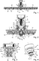
- the in the Fig. 1 and 2 The shower head shown comprises a shower head housing 1, a fluid inlet 2 in the showerhead housing 1, a shower jet outlet 3 from the showerhead housing 1, a fluid guide 4 in the shower head housing from the fluid inlet 2 to the shower jet outlet 3 and a pressure relief valve 5.
- the pressure relief valve 5 is pressure coupled to the fluid guide 4, ie a fluid pressure, which prevails in the fluid guide 4 in a corresponding region to which the pressure relief valve 5 is coupled in terms of technology acts on the pressure relief valve 5.
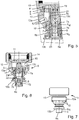
- the in the shower head of the Fig. 1 and 2 built-in pressure relief valve 5 is in the Fig. 3 to 7 illustrated in more detail. It is understood that this pressure relief valve can also be used in other shower heads.
- the pressure relief valve 5 includes a movable valve body 6, which at an overpressure in the fluid guide 4 from a normal position N S , as shown in the Fig. 3 to 5 is shown moving into a positive pressure position U S , as in the 6 and 7 and in the installed state of Fig. 1 and 2 is shown.
- the valve body 6 is designed such that it remains self-holding in the overpressure position U S and can be moved back into the normal position N S actuated by the user. This means that the valve body 5, when it has assumed its overpressure position due to an overpressure in the fluid guide 4, remains in the overpressure position U S until the user moves it back to the normal position N S , even if in the meantime the overpressure in the fluid guide 4 no longer available.
- the pressure relief valve 5 for this purpose a magnet assembly 7 which holds the valve body 6 by a magnetic force F M , which is surmounted by an overpressure of the fluid guide 4, in the normal position N S , wherein the magnetic force F M in their strength with increasing distance of the valve body 6 from the normal position N S decreases to an irrelevance value in the overpressure position Us.
- the pressure relief valve instead of such a magnet assembly includes another conventional holding power source, which acts on the valve body in the normal position N S with a overcome by the overpressure in the fluid guide 4 holding force, which no longer acts on the valve body 6 in the overpressure position Us or at least not so strong is that they could move the valve body 6 even with no longer existing excess pressure in the normal position N S.
- the magnet arrangement 7 is formed by two interacting magnets 7a, 7b, of which a first magnet 7b is arranged in or on the valve body 6 and a second magnet 7a is arranged in or on a stationary part of the overpressure valve 5.
- the two magnets 7a, 7b may, for example, be permanent magnets and provide the magnetic force F M as a magnetic attraction between the two magnets 7a, 7b which, as usual, rapidly decreases in magnitude as the distance between the two magnets 7a, 7b increases.
- the magnets 7a, 7b are suitably chosen so that they are in the normal position N S of the valve body 6, in the They have their smallest distance to provide the magnetic force F M in the required to hold the valve body 6 in its normal position N S strength, while the magnetic force F M in the overpressure position U S of the valve body 6, in which the two magnets 7 a, 7 b their maximum Have distance, practically dropped to zero or at least so far that they are no longer able to move the valve body 6 against any frictional forces and possibly present fluid pressure forces in the normal position N S.
- valve body 6 acts position-dependent on a passage cross-section D Q of the fluid guide 4 in such a way that it reduces the passage cross-section D Q in the overpressure position U S compared to the normal position N S.
- the valve body 6 is cylindrical and movable in the axial direction A R in the showerhead housing 1, wherein under axial direction A R as usual to be understood to a longitudinal center axis of the cylindrical valve body 6 parallel direction, as well as their opposite direction.
- the valve body 6 has a radially projecting annular collar 8 with at least one valve passage opening 9.
- the fluid guide 4 comprises a valve chamber 10, in which the valve body 6 is movably guided with its annular collar 8.
- the fluid guide 4 has at least one valve inlet opening 11 which opens into the valve chamber 10 and at least one valve outlet opening 12 which opens out from the valve chamber 10.
- the valve body 6 reduces with its annular collar 8 the passage cross section D Q of the at least one Ventilauslassö réelle 12 when the valve body 6 is in the overpressure position U S , compared with the operating condition when the valve body 6 is in the normal position N S.
- the valve body 6 reduces the passage cross section D Q of the fluid guide 4 in the region of the at least one valve outlet opening 12.
- the valve body acts at a different point of the fluid guide 4 on the passage cross section D Q in the sense of a reduction in excess pressure on.
- the reduction may be that the passage cross-section D Q is completely shut off, ie reduced to zero, or alternatively to a desired other reduced cross-sectional value between the value zero and a maximum value that the Passage cross section D Q has at the relevant point of the fluid guide 4, when the valve body 6 is in the overpressure position Us.
- valve chamber 10 the at least one valve inlet port 11 and the at least one valve outlet port 12 may be e.g. all be formed on the pressure relief valve 5.
- the valve chamber 10 is of annular cylindrical shape, alternatively it may have a different shape, e.g. a fully cylindrical shape.
- a plurality of valve inlet ports 11 and valve ports 9 are provided, e.g. each arranged equidistantly in the circumferential direction.
- both the at least one valve inlet opening 11 and the at least one valve passage opening 9 extend purely axially, ie parallel to the axial direction A R , the at least one valve passage opening 9 extending in alignment with the at least one valve inlet opening 11 when the valve body 6 is in the normal position N. S is located.
- the at least one valve inlet opening and / or the at least one valve passage opening runs at least in sections obliquely or perpendicular to the axial direction A R.
- the aligned transition from the respective valve inlet opening 11 to the respective valve passage opening 9 allows the fluid, in the normal position N S of the valve body 6, to pass unhindered through the at least one valve inlet opening 9 into the valve chamber 10 via the at least one valve inlet opening 11.
- valve body 6 is in the normal position N S with its respective valve passage opening 9 with no or at most a small distance from the respective valve inlet opening 11 in an associated Stirnend Scheme the valve chamber 10 opposite.
- the valve body 6 In the overpressure state U S , the valve body 6 is located with its annular collar 8 in the other end region of the valve chamber 10 and thus at a considerable distance from the or the valve inlet openings 11, so that even in the overpressure, the one or more valve inlet openings 11 are not blocked by the valve body 6.
- the pressure relief valve 5 includes a hollow cylindrical valve seat body 13, on which the valve body 6 is held out and in the valve chamber 10 is located.
- the at least one valve outlet opening 12 with a radial direction component extends outwardly through a cylinder jacket section 13a of the valve seat body 13.
- the valve seat body 13 is made of several parts joined together, in alternative embodiments, it is made in one piece. In the example shown, it is provided in an end region with an external thread 14, with which it can be screwed into an internal thread of a joint sleeve 15 of the shower head 1, as shown. Next, the valve seat body 13 in the example shown in an axially central region has an external thread 16 to which a shower outlet part 1a of the showerhead housing 1 is screwed. In alternative embodiments, the valve seat body 13 is connectable in another conventional manner with the showerhead housing.
- the shower outlet part 1a is manufactured in a flat shower construction, whereby the shower head of the Fig. 1 and 2 especially suitable as a flat overhead shower, as is known per se for use in sanitary shower rooms or shower facilities.
- the effervescent outlet part 1a is articulated via a ball joint 16 to a shower head connection part 1b, via which the shower head can be connected to a fluid supply and which forms the fluid inlet 2.
- the shower head is not configured in this flat design, but of another conventional design, such as a bell-shaped design.
- a sieve element 17 is arranged as a dirt / particle sieve.
- the effervescent outlet part 1a has a structure known per se apart from the pressure relief valve 5, which terminates with a spray jet 18 forming the effervescent jet outlet 3, which is provided with one or mostly a plurality of jet outlet openings 19, which in a predeterminable configuration have a circular or quadrangular configuration, for example Exit surface of the jet disk 18 away are arranged.
- the fluid guide 4 upstream of the jet outlet openings 19, a distribution chamber 20, from the the jet outlet openings 19 open and into which the at least one valve outlet opening 12 opens.
- the valve body 6 acts on the passage cross-section D Q of the fluid guide 4 between the fluid inlet 2 and the distribution chamber 20, in particular between the valve chamber 10 and the distribution chamber 20th
- valve body 6 is located on a same side of the showerhead housing 1 as the jet disk 18 forming the effervescent spray outlet 3. In the embodiment shown, the valve body 6 is located specifically in a central region of the jet disk 18. In alternative embodiments, the valve body 6 is with respect to the jet disk 18 arranged eccentrically.
- the valve body 6 is in the overpressure position Us from the outside of the jet disk 18.
- the shower head is in the Fig. 1 and 2 shown.
- the valve body 6 does not protrude from the outside of the jet disk 18, ie it is positioned in the interior of the shower head housing 1 in a recessed position or terminates substantially flush with the outside of the jet disk 18.
- the latter is realized in the example shown, ie in the normal position N S an outer side 6a of the valve body 6 is aligned with an outer side 13b of the valve seat body 13, which in turn terminates substantially flush with the outer side of the jet disk 18.
- a center pin 13c formed which limits the annular valve chamber 10 radially inwardly and can act as an additional guide for the valve body 6, including the valve body 6 in an associated section 6c axially between its foot-side annular collar 8 and a final with the outside 6a head portion 6b is formed correspondingly hollow cylindrical.
- a pressure passage 21 which is in fluid communication with the valve chamber 10 and leads axially forward to an end face 22 of the valve body head portion 6b.
- the pressure channel 21 includes one or more radial gaps extending axially or with an axial directional component, e.g. may each be formed by an axial or axial direction component extending groove on the outside of the center pin 13c and / or on the inside of the hollow cylindrical valve body portion 6c.
- a circumferentially continuous annular gap may be provided as a pressure channel 21, or there may be provided axially or with axial direction component extending spacer webs on at least one of these two opposing surfaces, between which then the pressure channel 21 forming spaces.
- the center pin 13c simultaneously serves to hold the second magnet 7a, while the first magnet 7b is arranged in the head portion 6b of the valve body 6.
- the magnets 7a, 7b can be inserted there into corresponding bores, which can be closed off by means of the center pin 13c by way of example with a sealing screw 23 and on the part of the valve body 6 with a cap 24 defining the outside 6a of the valve body 6.
- these magnetic insert bores may remain unlocked or otherwise terminated.
- the respective Ventilauslassö réelle 12 empties in a lower in the figures of the valve chamber 10 from this and extends radially outward and axially forward or outward, i. in the figures, down through the relevant cylinder jacket section 13a of the valve seat body 13, which in this region is e.g. Conically tapered can be designed as shown.
- a plurality of valve outlet openings 12 are provided distributed in the circumferential direction equidistantly.
- the number of valve outlet openings 12 may correspond to or be different from the number of valve passage openings 9.
- N S is the valve body 6 with its annular collar 8 at the inner or rear, ie in the figures upper, end of the valve chamber 10, wherein the respective valve passage opening 9 in alignment with the associated valve inlet opening 11 and in this area the pressure channel 21 opens.
- the valve outlet openings 12 are completely released, without the valve body 6 having the defined by the overall configuration of the shower head passage cross-section D Q of Fluid guide 4 limited. Consequently, fluid supplied via the fluid inlet 2 passes in this normal operation of the shower head via the fluid guide 4 to the shower jet outlet 3, where it exits as a corresponding shower jet. More specifically, in this case, the fluid flows via the valve inlet openings 11 and the valve passage openings 9 into the valve chamber 10 and from there via the valve outlet openings 12 into the distribution chamber 20, from where it distributes onto the jet outlet openings 19.
- an overpressure occurs, for example in the distribution chamber 20, this leads to a corresponding overpressure in the valve chamber 10 of the pressure-coupled to the fluid guide 4 pressure relief valve 5.
- the pressure in the valve chamber 10 pushes the fluid into the pressure channel 21, whereby the fluid with the appropriate pressure against the end face 22 of the valve body 6 presses.
- the magnet arrangement 7 is designed such that the magnetic force F M provided by it in the normal position N S of the valve body 6 is smaller than the oppositely acting fluid overpressure force, which is the fluid under overpressure on the valve body 6 exerts on the end face 22.
- valve body 6 disengages against the magnetic force F M from its normal position N S and moves the fluid overpressure force axially forward or outward, ie in the figures down to its overpressure position U S , which the normal position N S opposite End position of the valve body 6 represents.
- This extension movement of the valve body 6 against the magnetic force F M and against any frictional forces and against the pressure acting on the outside 6a of the valve body 6 ambient pressure can be supported by a Mitr clutch effectively a residual flow of fluid in the valve chamber 10 with appropriate system design.
- the pressure relief valve 5 also responds when the shower head is connected to a fluid supply, the fluid supply pressure is greater than that for which the shower head is designed.
- the valve body 6 In the overpressure position U S, the valve body 6, with its annular collar 8, completely or alternatively partially blocks the respective valve outlet opening 12, as for example in FIGS Fig. 2 and 5 can be seen.
- the valve body 6 reduces the passage cross section D Q of the fluid guide 4 to zero or at least to a value which is lower than the effective passage cross section of the fluid guide 4 during normal operation. This has the consequence that the flow rate of the fluid at the effervescent outlet 3 is reduced accordingly. For the user, this is easily recognizable by the fact that the shower jet stops or the shower head only drips at the shower outlet 3.
- the user can recognize the occurred overpressure case in that the valve body 6 has moved into its extended overpressure position U S and therefore projects forward or outward from the outside of the jet disk 18.
- the valve body 6, at least in its area projecting from the jet disk 18, can be made in a color-contrasting manner from the surrounding jet disk area. This can make it even easier for the user to recognize that the pressure relief valve 5 has responded.
- the fluid can no longer or at least not flow in a significant amount into the distribution chamber 20 in the overpressure position Us of the valve body 6, so that there initially existing overpressure due to the escape of the remaining fluid at the shower outlet 3 can reduce.
- the user can now take the necessary action For example, clean the shower head as a whole or at least at the shower outlet 3, ie eliminate the cause of the occurred overpressure case.
- the valve body 6 in this case initially remains in its overpressure position Us, since the two magnets 7a, 7b are now so far apart that they exert no or at least no significant magnetic force more on the valve body 6, ie, the magnet assembly 7 is not able withdraw the valve body 6 automatically in the normal position N S.
- valve body 6 After the user has eliminated the cause of the fluid overpressure, he pushes the valve body 6 back into its normal position N S , for example by pressing with a finger against the outside 6 a of the valve body 6.
- the valve body 6 forms in the example shown with its head portion 6b quasi a valve pin, which the user can push back from the extended overpressure position Us in the retracted normal position N S.
- the magnet assembly 7 then holds with its magnetic force F M the valve body 6 again in its normal position N S.
- the valve body 6 again completely releases the passage cross-section D Q of the fluid guide 4, in the example shown by completely releasing the valve outlet openings 12.
- the shower head is thus ready for use again.
- the invention provides a shower head with an advantageous overpressure valve function. Damage to the shower head can be avoided by the integrated pressure relief valve.
- the overpressure valve can provide in corresponding implementations of the shower head for a reduction of the fluid volume flow, so that the excess pressure can be reduced by residual leakage of fluid from the shower head, preferably on the Effervescent outlet, without the pressure relief valve itself leaking fluid.
- the user can easily detect an overpressure case in corresponding implementations of the shower head, eliminate the causes of the overpressure and then bring the valve body back from its overpressure position into its normal position under its own control.
- the shower head according to the invention can be used for any type of sanitary showers as well as for non-sanitary showers, if and insofar There is a need to protect the showerhead from any fluid overpressure in the fluid guide.
Landscapes
- Health & Medical Sciences (AREA)
- Public Health (AREA)
- Epidemiology (AREA)
- General Health & Medical Sciences (AREA)
- Bathtubs, Showers, And Their Attachments (AREA)
- Safety Valves (AREA)
- Nozzles (AREA)
Applications Claiming Priority (1)
| Application Number | Priority Date | Filing Date | Title |
|---|---|---|---|
| DE102018201109.5A DE102018201109B3 (de) | 2018-01-24 | 2018-01-24 | Brausekopf mit Überdruckventil |
Publications (2)
| Publication Number | Publication Date |
|---|---|
| EP3517211A1 true EP3517211A1 (fr) | 2019-07-31 |
| EP3517211B1 EP3517211B1 (fr) | 2020-06-24 |
Family
ID=64567974
Family Applications (1)
| Application Number | Title | Priority Date | Filing Date |
|---|---|---|---|
| EP19152805.8A Active EP3517211B1 (fr) | 2018-01-24 | 2019-01-21 | Pomme de douche à vanne de surpression |
Country Status (6)
| Country | Link |
|---|---|
| US (1) | US11059057B2 (fr) |
| EP (1) | EP3517211B1 (fr) |
| CN (1) | CN110064537B (fr) |
| DE (1) | DE102018201109B3 (fr) |
| RU (1) | RU2701933C1 (fr) |
| ZA (1) | ZA201900167B (fr) |
Families Citing this family (4)
| Publication number | Priority date | Publication date | Assignee | Title |
|---|---|---|---|---|
| DE102018201109B3 (de) * | 2018-01-24 | 2018-12-27 | Hansgrohe Se | Brausekopf mit Überdruckventil |
| EP3597832B1 (fr) * | 2018-07-20 | 2021-07-21 | Nikles Tec Italia S.r.l. | Dispositif de distribution d'un jet d'eau avec soupape de sécurité |
| EP3939705A1 (fr) * | 2020-07-14 | 2022-01-19 | Andreas Stihl AG & Co. KG | Appareil de nettoyage haute pression |
| CN215465284U (zh) * | 2021-05-20 | 2022-01-11 | 南昌科勒有限公司 | 一种花洒 |
Citations (4)
| Publication number | Priority date | Publication date | Assignee | Title |
|---|---|---|---|---|
| CH442165A (de) * | 1965-06-23 | 1967-08-15 | Seidl Karl | Brausekopf, insbesondere von einer Handbrause mit Überdrucksicherung |
| CN202527296U (zh) * | 2012-04-06 | 2012-11-14 | 辉煌水暖集团有限公司 | 一种带自动泄压功能的花洒 |
| EP2848315A1 (fr) * | 2012-05-10 | 2015-03-18 | Xiamen Solex High-Tech Industries Co., Ltd. | Tête sphérique antidéflagrante |
| DE102015003607A1 (de) * | 2015-03-23 | 2016-09-29 | Grohe Ag | Brausekopf für eine Sanitärbrause |
Family Cites Families (19)
| Publication number | Priority date | Publication date | Assignee | Title |
|---|---|---|---|---|
| AT252826B (de) | 1965-06-23 | 1967-03-10 | Seidl Karl | Brausekopf, insbesondere von Hand- oder Schlauchbrausen, mit Überdrucksicherung |
| KR970028016A (ko) * | 1997-03-12 | 1997-06-24 | 박연수 | 자동개폐장치의 제작방법 및 그 구성 |
| AU2003293850A1 (en) * | 2002-12-12 | 2004-06-30 | Hansgrohe Ag | Shower head with air introduction |
| EP1619315A1 (fr) * | 2004-07-22 | 2006-01-25 | Elast Kunststoffverarbeitungs-GmbH & Co. KEG | Régulateur de jet |
| CN100471577C (zh) * | 2006-01-17 | 2009-03-25 | 潘尧钊 | 淋浴喷头的出水控制机构 |
| DE102009008194B4 (de) * | 2009-02-02 | 2011-07-28 | Hansgrohe AG, 77761 | Sanitäres Abschalt- beziehungsweise Umschaltventil |
| US9095860B2 (en) * | 2009-12-31 | 2015-08-04 | Xiamen Solex High-Tech Industries Co., Ltd. | Shower with waterway switch controlled by electronic touch |
| RU2534088C1 (ru) * | 2010-10-01 | 2014-11-27 | Гроэ Аг | Душевая головка |
| US9242262B2 (en) * | 2012-05-25 | 2016-01-26 | Delta Faucet Company | Body spray with extending sprayhead |
| DE102012212300A1 (de) * | 2012-07-13 | 2014-01-16 | Hansgrohe Se | Brause |
| DE102013218741B4 (de) * | 2013-09-18 | 2015-12-24 | Aptar Radolfzell Gmbh | Spendersystem |
| CN103611643B (zh) | 2013-12-11 | 2016-08-17 | 厦门松霖科技有限公司 | 一种防爆球头 |
| CN105983492B (zh) * | 2015-02-04 | 2018-07-03 | 厦门松霖科技股份有限公司 | 一种多功能花洒 |
| CN104971834A (zh) * | 2015-06-30 | 2015-10-14 | 开平市汉顺洁具实业有限公司 | 一种防爆花洒 |
| CN204933765U (zh) * | 2015-08-14 | 2016-01-06 | 厦门松霖科技有限公司 | 一种关水复位顶喷花洒 |
| CN106140504B (zh) * | 2016-03-08 | 2019-03-22 | 福建西河卫浴科技有限公司 | 一种组合花洒及其切换出水的方法 |
| CN106269322B (zh) * | 2016-10-14 | 2019-12-03 | 浙江花乐科技股份有限公司 | 组合花洒 |
| DE102018201109B3 (de) * | 2018-01-24 | 2018-12-27 | Hansgrohe Se | Brausekopf mit Überdruckventil |
| EP3597832B1 (fr) * | 2018-07-20 | 2021-07-21 | Nikles Tec Italia S.r.l. | Dispositif de distribution d'un jet d'eau avec soupape de sécurité |
-
2018
- 2018-01-24 DE DE102018201109.5A patent/DE102018201109B3/de not_active Expired - Fee Related
-
2019
- 2019-01-10 ZA ZA2019/00167A patent/ZA201900167B/en unknown
- 2019-01-18 RU RU2019101432A patent/RU2701933C1/ru active
- 2019-01-21 EP EP19152805.8A patent/EP3517211B1/fr active Active
- 2019-01-23 US US16/255,787 patent/US11059057B2/en active Active
- 2019-01-24 CN CN201910068872.4A patent/CN110064537B/zh active Active
Patent Citations (4)
| Publication number | Priority date | Publication date | Assignee | Title |
|---|---|---|---|---|
| CH442165A (de) * | 1965-06-23 | 1967-08-15 | Seidl Karl | Brausekopf, insbesondere von einer Handbrause mit Überdrucksicherung |
| CN202527296U (zh) * | 2012-04-06 | 2012-11-14 | 辉煌水暖集团有限公司 | 一种带自动泄压功能的花洒 |
| EP2848315A1 (fr) * | 2012-05-10 | 2015-03-18 | Xiamen Solex High-Tech Industries Co., Ltd. | Tête sphérique antidéflagrante |
| DE102015003607A1 (de) * | 2015-03-23 | 2016-09-29 | Grohe Ag | Brausekopf für eine Sanitärbrause |
Also Published As
| Publication number | Publication date |
|---|---|
| CN110064537A (zh) | 2019-07-30 |
| US20190224696A1 (en) | 2019-07-25 |
| RU2701933C1 (ru) | 2019-10-02 |
| US11059057B2 (en) | 2021-07-13 |
| ZA201900167B (en) | 2019-08-28 |
| DE102018201109B3 (de) | 2018-12-27 |
| CN110064537B (zh) | 2021-11-19 |
| EP3517211B1 (fr) | 2020-06-24 |
Similar Documents
| Publication | Publication Date | Title |
|---|---|---|
| EP2664719B1 (fr) | Élément d'installation sanitaire | |
| EP3517212B1 (fr) | Dispositif de génération de jets de douche à vanne de surpression | |
| EP3517211B1 (fr) | Pomme de douche à vanne de surpression | |
| EP1918465B1 (fr) | Régulateur jet comprenant une codification en couleur du débit | |
| EP3305412B1 (fr) | Dispositif de production de jets | |
| DE102015016902A1 (de) | Ventilkäfig zum Aufnehmen eines Ventilglieds und Verfahren zum Betätigen eines Stellventils mit einem Ventilkäfig und einem Ventilglied | |
| DE2816139A1 (de) | Dosierventil | |
| EP3513008B1 (fr) | Unité d'écoulement sanitaire | |
| DE202007009832U1 (de) | Anschlussarmatur | |
| DE102007054673B4 (de) | Bandschmiereinrichtung und/oder Reinigungs-Desinfektionsanlage | |
| DE102016225987A1 (de) | Brausestrahlaustrittsvorrichtung und damit ausgerüstete Brause | |
| EP3325864B1 (fr) | Vanne de régulation commandée par son propre fluide | |
| WO2009006956A1 (fr) | Évacuation d'eau pour une installation sanitaire basse pression | |
| EP3268830A1 (fr) | Unité de régulation du débit | |
| DE2050749B2 (de) | Strahlregler für Wasserleitungshähne | |
| EP3300807B1 (fr) | Dispositif d'étranglement de l'écoulement et douche sanitaire | |
| DE102006053625A1 (de) | Rotordüse | |
| EP3599399B1 (fr) | Soupape sanitaire pourvue d'une soupape à membrane | |
| EP4133198B1 (fr) | Dispositif de commutation | |
| DE102011076049B4 (de) | Strahlregler | |
| DE19729053B4 (de) | Düse zur Staubbekämpfung im untertägigen Berg- und Tunnelbau mit einer staubbindenden Flüssigkeit | |
| DE102015001025A1 (de) | Sanitärarmatur | |
| EP0854407A1 (fr) | Appareil de régulation de pression de gaz | |
| DE102007032839B4 (de) | Wasserauslauf für eine sanitäre Niederdruck-Auslaufarmatur | |
| DE102009009852B4 (de) | Plattenablaufventil, insbesondere zum Beeinflussen des Ansteuerdrucks eines Regelventils |
Legal Events
| Date | Code | Title | Description |
|---|---|---|---|
| PUAI | Public reference made under article 153(3) epc to a published international application that has entered the european phase |
Free format text: ORIGINAL CODE: 0009012 |
|
| STAA | Information on the status of an ep patent application or granted ep patent |
Free format text: STATUS: THE APPLICATION HAS BEEN PUBLISHED |
|
| AK | Designated contracting states |
Kind code of ref document: A1 Designated state(s): AL AT BE BG CH CY CZ DE DK EE ES FI FR GB GR HR HU IE IS IT LI LT LU LV MC MK MT NL NO PL PT RO RS SE SI SK SM TR |
|
| AX | Request for extension of the european patent |
Extension state: BA ME |
|
| STAA | Information on the status of an ep patent application or granted ep patent |
Free format text: STATUS: REQUEST FOR EXAMINATION WAS MADE |
|
| 17P | Request for examination filed |
Effective date: 20191017 |
|
| RBV | Designated contracting states (corrected) |
Designated state(s): AL AT BE BG CH CY CZ DE DK EE ES FI FR GB GR HR HU IE IS IT LI LT LU LV MC MK MT NL NO PL PT RO RS SE SI SK SM TR |
|
| RIC1 | Information provided on ipc code assigned before grant |
Ipc: B05B 12/08 20060101ALI20191105BHEP Ipc: B05B 1/18 20060101AFI20191105BHEP Ipc: B05B 15/654 20180101ALI20191105BHEP Ipc: B05B 15/50 20180101ALI20191105BHEP |
|
| GRAP | Despatch of communication of intention to grant a patent |
Free format text: ORIGINAL CODE: EPIDOSNIGR1 |
|
| STAA | Information on the status of an ep patent application or granted ep patent |
Free format text: STATUS: GRANT OF PATENT IS INTENDED |
|
| INTG | Intention to grant announced |
Effective date: 20200115 |
|
| GRAS | Grant fee paid |
Free format text: ORIGINAL CODE: EPIDOSNIGR3 |
|
| GRAA | (expected) grant |
Free format text: ORIGINAL CODE: 0009210 |
|
| STAA | Information on the status of an ep patent application or granted ep patent |
Free format text: STATUS: THE PATENT HAS BEEN GRANTED |
|
| AK | Designated contracting states |
Kind code of ref document: B1 Designated state(s): AL AT BE BG CH CY CZ DE DK EE ES FI FR GB GR HR HU IE IS IT LI LT LU LV MC MK MT NL NO PL PT RO RS SE SI SK SM TR |
|
| REG | Reference to a national code |
Ref country code: GB Ref legal event code: FG4D Free format text: NOT ENGLISH |
|
| REG | Reference to a national code |
Ref country code: CH Ref legal event code: EP |
|
| REG | Reference to a national code |
Ref country code: DE Ref legal event code: R096 Ref document number: 502019000068 Country of ref document: DE |
|
| REG | Reference to a national code |
Ref country code: AT Ref legal event code: REF Ref document number: 1283363 Country of ref document: AT Kind code of ref document: T Effective date: 20200715 |
|
| REG | Reference to a national code |
Ref country code: IE Ref legal event code: FG4D Free format text: LANGUAGE OF EP DOCUMENT: GERMAN |
|
| PG25 | Lapsed in a contracting state [announced via postgrant information from national office to epo] |
Ref country code: NO Free format text: LAPSE BECAUSE OF FAILURE TO SUBMIT A TRANSLATION OF THE DESCRIPTION OR TO PAY THE FEE WITHIN THE PRESCRIBED TIME-LIMIT Effective date: 20200924 Ref country code: GR Free format text: LAPSE BECAUSE OF FAILURE TO SUBMIT A TRANSLATION OF THE DESCRIPTION OR TO PAY THE FEE WITHIN THE PRESCRIBED TIME-LIMIT Effective date: 20200925 Ref country code: FI Free format text: LAPSE BECAUSE OF FAILURE TO SUBMIT A TRANSLATION OF THE DESCRIPTION OR TO PAY THE FEE WITHIN THE PRESCRIBED TIME-LIMIT Effective date: 20200624 Ref country code: LT Free format text: LAPSE BECAUSE OF FAILURE TO SUBMIT A TRANSLATION OF THE DESCRIPTION OR TO PAY THE FEE WITHIN THE PRESCRIBED TIME-LIMIT Effective date: 20200624 Ref country code: SE Free format text: LAPSE BECAUSE OF FAILURE TO SUBMIT A TRANSLATION OF THE DESCRIPTION OR TO PAY THE FEE WITHIN THE PRESCRIBED TIME-LIMIT Effective date: 20200624 |
|
| REG | Reference to a national code |
Ref country code: LT Ref legal event code: MG4D |
|
| PG25 | Lapsed in a contracting state [announced via postgrant information from national office to epo] |
Ref country code: HR Free format text: LAPSE BECAUSE OF FAILURE TO SUBMIT A TRANSLATION OF THE DESCRIPTION OR TO PAY THE FEE WITHIN THE PRESCRIBED TIME-LIMIT Effective date: 20200624 Ref country code: RS Free format text: LAPSE BECAUSE OF FAILURE TO SUBMIT A TRANSLATION OF THE DESCRIPTION OR TO PAY THE FEE WITHIN THE PRESCRIBED TIME-LIMIT Effective date: 20200624 Ref country code: BG Free format text: LAPSE BECAUSE OF FAILURE TO SUBMIT A TRANSLATION OF THE DESCRIPTION OR TO PAY THE FEE WITHIN THE PRESCRIBED TIME-LIMIT Effective date: 20200924 Ref country code: LV Free format text: LAPSE BECAUSE OF FAILURE TO SUBMIT A TRANSLATION OF THE DESCRIPTION OR TO PAY THE FEE WITHIN THE PRESCRIBED TIME-LIMIT Effective date: 20200624 |
|
| REG | Reference to a national code |
Ref country code: NL Ref legal event code: MP Effective date: 20200624 |
|
| PG25 | Lapsed in a contracting state [announced via postgrant information from national office to epo] |
Ref country code: NL Free format text: LAPSE BECAUSE OF FAILURE TO SUBMIT A TRANSLATION OF THE DESCRIPTION OR TO PAY THE FEE WITHIN THE PRESCRIBED TIME-LIMIT Effective date: 20200624 Ref country code: AL Free format text: LAPSE BECAUSE OF FAILURE TO SUBMIT A TRANSLATION OF THE DESCRIPTION OR TO PAY THE FEE WITHIN THE PRESCRIBED TIME-LIMIT Effective date: 20200624 |
|
| PG25 | Lapsed in a contracting state [announced via postgrant information from national office to epo] |
Ref country code: EE Free format text: LAPSE BECAUSE OF FAILURE TO SUBMIT A TRANSLATION OF THE DESCRIPTION OR TO PAY THE FEE WITHIN THE PRESCRIBED TIME-LIMIT Effective date: 20200624 Ref country code: IT Free format text: LAPSE BECAUSE OF FAILURE TO SUBMIT A TRANSLATION OF THE DESCRIPTION OR TO PAY THE FEE WITHIN THE PRESCRIBED TIME-LIMIT Effective date: 20200624 Ref country code: SM Free format text: LAPSE BECAUSE OF FAILURE TO SUBMIT A TRANSLATION OF THE DESCRIPTION OR TO PAY THE FEE WITHIN THE PRESCRIBED TIME-LIMIT Effective date: 20200624 Ref country code: RO Free format text: LAPSE BECAUSE OF FAILURE TO SUBMIT A TRANSLATION OF THE DESCRIPTION OR TO PAY THE FEE WITHIN THE PRESCRIBED TIME-LIMIT Effective date: 20200624 Ref country code: CZ Free format text: LAPSE BECAUSE OF FAILURE TO SUBMIT A TRANSLATION OF THE DESCRIPTION OR TO PAY THE FEE WITHIN THE PRESCRIBED TIME-LIMIT Effective date: 20200624 Ref country code: ES Free format text: LAPSE BECAUSE OF FAILURE TO SUBMIT A TRANSLATION OF THE DESCRIPTION OR TO PAY THE FEE WITHIN THE PRESCRIBED TIME-LIMIT Effective date: 20200624 Ref country code: PT Free format text: LAPSE BECAUSE OF FAILURE TO SUBMIT A TRANSLATION OF THE DESCRIPTION OR TO PAY THE FEE WITHIN THE PRESCRIBED TIME-LIMIT Effective date: 20201026 |
|
| PG25 | Lapsed in a contracting state [announced via postgrant information from national office to epo] |
Ref country code: PL Free format text: LAPSE BECAUSE OF FAILURE TO SUBMIT A TRANSLATION OF THE DESCRIPTION OR TO PAY THE FEE WITHIN THE PRESCRIBED TIME-LIMIT Effective date: 20200624 Ref country code: SK Free format text: LAPSE BECAUSE OF FAILURE TO SUBMIT A TRANSLATION OF THE DESCRIPTION OR TO PAY THE FEE WITHIN THE PRESCRIBED TIME-LIMIT Effective date: 20200624 Ref country code: IS Free format text: LAPSE BECAUSE OF FAILURE TO SUBMIT A TRANSLATION OF THE DESCRIPTION OR TO PAY THE FEE WITHIN THE PRESCRIBED TIME-LIMIT Effective date: 20201024 |
|
| REG | Reference to a national code |
Ref country code: DE Ref legal event code: R097 Ref document number: 502019000068 Country of ref document: DE |
|
| PG25 | Lapsed in a contracting state [announced via postgrant information from national office to epo] |
Ref country code: DK Free format text: LAPSE BECAUSE OF FAILURE TO SUBMIT A TRANSLATION OF THE DESCRIPTION OR TO PAY THE FEE WITHIN THE PRESCRIBED TIME-LIMIT Effective date: 20200624 |
|
| PLBE | No opposition filed within time limit |
Free format text: ORIGINAL CODE: 0009261 |
|
| STAA | Information on the status of an ep patent application or granted ep patent |
Free format text: STATUS: NO OPPOSITION FILED WITHIN TIME LIMIT |
|
| 26N | No opposition filed |
Effective date: 20210325 |
|
| PG25 | Lapsed in a contracting state [announced via postgrant information from national office to epo] |
Ref country code: SI Free format text: LAPSE BECAUSE OF FAILURE TO SUBMIT A TRANSLATION OF THE DESCRIPTION OR TO PAY THE FEE WITHIN THE PRESCRIBED TIME-LIMIT Effective date: 20200624 Ref country code: MC Free format text: LAPSE BECAUSE OF FAILURE TO SUBMIT A TRANSLATION OF THE DESCRIPTION OR TO PAY THE FEE WITHIN THE PRESCRIBED TIME-LIMIT Effective date: 20200624 |
|
| PG25 | Lapsed in a contracting state [announced via postgrant information from national office to epo] |
Ref country code: LU Free format text: LAPSE BECAUSE OF NON-PAYMENT OF DUE FEES Effective date: 20210121 |
|
| REG | Reference to a national code |
Ref country code: BE Ref legal event code: MM Effective date: 20210131 |
|
| PG25 | Lapsed in a contracting state [announced via postgrant information from national office to epo] |
Ref country code: IE Free format text: LAPSE BECAUSE OF NON-PAYMENT OF DUE FEES Effective date: 20210121 |
|
| PG25 | Lapsed in a contracting state [announced via postgrant information from national office to epo] |
Ref country code: BE Free format text: LAPSE BECAUSE OF NON-PAYMENT OF DUE FEES Effective date: 20210131 |
|
| REG | Reference to a national code |
Ref country code: CH Ref legal event code: PL |
|
| PG25 | Lapsed in a contracting state [announced via postgrant information from national office to epo] |
Ref country code: LI Free format text: LAPSE BECAUSE OF NON-PAYMENT OF DUE FEES Effective date: 20220131 Ref country code: CH Free format text: LAPSE BECAUSE OF NON-PAYMENT OF DUE FEES Effective date: 20220131 |
|
| PG25 | Lapsed in a contracting state [announced via postgrant information from national office to epo] |
Ref country code: CY Free format text: LAPSE BECAUSE OF FAILURE TO SUBMIT A TRANSLATION OF THE DESCRIPTION OR TO PAY THE FEE WITHIN THE PRESCRIBED TIME-LIMIT Effective date: 20200624 |
|
| PG25 | Lapsed in a contracting state [announced via postgrant information from national office to epo] |
Ref country code: HU Free format text: LAPSE BECAUSE OF FAILURE TO SUBMIT A TRANSLATION OF THE DESCRIPTION OR TO PAY THE FEE WITHIN THE PRESCRIBED TIME-LIMIT; INVALID AB INITIO Effective date: 20190121 |
|
| PG25 | Lapsed in a contracting state [announced via postgrant information from national office to epo] |
Ref country code: MK Free format text: LAPSE BECAUSE OF FAILURE TO SUBMIT A TRANSLATION OF THE DESCRIPTION OR TO PAY THE FEE WITHIN THE PRESCRIBED TIME-LIMIT Effective date: 20200624 |
|
| PG25 | Lapsed in a contracting state [announced via postgrant information from national office to epo] |
Ref country code: MT Free format text: LAPSE BECAUSE OF FAILURE TO SUBMIT A TRANSLATION OF THE DESCRIPTION OR TO PAY THE FEE WITHIN THE PRESCRIBED TIME-LIMIT Effective date: 20200624 |
|
| REG | Reference to a national code |
Ref country code: AT Ref legal event code: MM01 Ref document number: 1283363 Country of ref document: AT Kind code of ref document: T Effective date: 20240121 |
|
| PG25 | Lapsed in a contracting state [announced via postgrant information from national office to epo] |
Ref country code: AT Free format text: LAPSE BECAUSE OF NON-PAYMENT OF DUE FEES Effective date: 20240121 |
|
| PG25 | Lapsed in a contracting state [announced via postgrant information from national office to epo] |
Ref country code: TR Free format text: LAPSE BECAUSE OF FAILURE TO SUBMIT A TRANSLATION OF THE DESCRIPTION OR TO PAY THE FEE WITHIN THE PRESCRIBED TIME-LIMIT Effective date: 20200624 |
|
| PGFP | Annual fee paid to national office [announced via postgrant information from national office to epo] |
Ref country code: GB Payment date: 20260126 Year of fee payment: 8 |
|
| PGFP | Annual fee paid to national office [announced via postgrant information from national office to epo] |
Ref country code: DE Payment date: 20260127 Year of fee payment: 8 |
|
| PGFP | Annual fee paid to national office [announced via postgrant information from national office to epo] |
Ref country code: AT Payment date: 20260410 Year of fee payment: 5 |
|
| PGFP | Annual fee paid to national office [announced via postgrant information from national office to epo] |
Ref country code: FR Payment date: 20260126 Year of fee payment: 8 |