EP3517255A2 - Robotersteuerungsvorrichtung, robotersystem und verfahren zur erstellung eines steuerungsprogramms - Google Patents
Robotersteuerungsvorrichtung, robotersystem und verfahren zur erstellung eines steuerungsprogramms Download PDFInfo
- Publication number
- EP3517255A2 EP3517255A2 EP19153471.8A EP19153471A EP3517255A2 EP 3517255 A2 EP3517255 A2 EP 3517255A2 EP 19153471 A EP19153471 A EP 19153471A EP 3517255 A2 EP3517255 A2 EP 3517255A2
- Authority
- EP
- European Patent Office
- Prior art keywords
- work
- robot
- parameters
- control device
- force
- Prior art date
- Legal status (The legal status is an assumption and is not a legal conclusion. Google has not performed a legal analysis and makes no representation as to the accuracy of the status listed.)
- Pending
Links
Images









Classifications
-
- B—PERFORMING OPERATIONS; TRANSPORTING
- B25—HAND TOOLS; PORTABLE POWER-DRIVEN TOOLS; MANIPULATORS
- B25J—MANIPULATORS; CHAMBERS PROVIDED WITH MANIPULATION DEVICES
- B25J9/00—Program-controlled manipulators
- B25J9/16—Program controls
- B25J9/1656—Program controls characterised by programming, planning systems for manipulators
- B25J9/1658—Program controls characterised by programming, planning systems for manipulators characterised by programming language
-
- B—PERFORMING OPERATIONS; TRANSPORTING
- B25—HAND TOOLS; PORTABLE POWER-DRIVEN TOOLS; MANIPULATORS
- B25J—MANIPULATORS; CHAMBERS PROVIDED WITH MANIPULATION DEVICES
- B25J9/00—Program-controlled manipulators
- B25J9/16—Program controls
- B25J9/1656—Program controls characterised by programming, planning systems for manipulators
-
- B—PERFORMING OPERATIONS; TRANSPORTING
- B25—HAND TOOLS; PORTABLE POWER-DRIVEN TOOLS; MANIPULATORS
- B25J—MANIPULATORS; CHAMBERS PROVIDED WITH MANIPULATION DEVICES
- B25J13/00—Controls for manipulators
- B25J13/06—Control stands, e.g. consoles, switchboards
-
- B—PERFORMING OPERATIONS; TRANSPORTING
- B25—HAND TOOLS; PORTABLE POWER-DRIVEN TOOLS; MANIPULATORS
- B25J—MANIPULATORS; CHAMBERS PROVIDED WITH MANIPULATION DEVICES
- B25J13/00—Controls for manipulators
- B25J13/08—Controls for manipulators by means of sensing devices, e.g. viewing or touching devices
-
- B—PERFORMING OPERATIONS; TRANSPORTING
- B25—HAND TOOLS; PORTABLE POWER-DRIVEN TOOLS; MANIPULATORS
- B25J—MANIPULATORS; CHAMBERS PROVIDED WITH MANIPULATION DEVICES
- B25J9/00—Program-controlled manipulators
- B25J9/0081—Program-controlled manipulators with leader teach-in means
-
- B—PERFORMING OPERATIONS; TRANSPORTING
- B25—HAND TOOLS; PORTABLE POWER-DRIVEN TOOLS; MANIPULATORS
- B25J—MANIPULATORS; CHAMBERS PROVIDED WITH MANIPULATION DEVICES
- B25J9/00—Program-controlled manipulators
- B25J9/16—Program controls
-
- B—PERFORMING OPERATIONS; TRANSPORTING
- B25—HAND TOOLS; PORTABLE POWER-DRIVEN TOOLS; MANIPULATORS
- B25J—MANIPULATORS; CHAMBERS PROVIDED WITH MANIPULATION DEVICES
- B25J9/00—Program-controlled manipulators
- B25J9/16—Program controls
- B25J9/1628—Program controls characterised by the control loop
- B25J9/1633—Program controls characterised by the control loop compliant, force, torque control, e.g. combined with position control
-
- B—PERFORMING OPERATIONS; TRANSPORTING
- B25—HAND TOOLS; PORTABLE POWER-DRIVEN TOOLS; MANIPULATORS
- B25J—MANIPULATORS; CHAMBERS PROVIDED WITH MANIPULATION DEVICES
- B25J9/00—Program-controlled manipulators
- B25J9/16—Program controls
- B25J9/1656—Program controls characterised by programming, planning systems for manipulators
- B25J9/1671—Program controls characterised by programming, planning systems for manipulators characterised by simulation, either to verify existing program or to create and verify new program, CAD/CAM oriented, graphic oriented programming systems
-
- G—PHYSICS
- G05—CONTROLLING; REGULATING
- G05B—CONTROL OR REGULATING SYSTEMS IN GENERAL; FUNCTIONAL ELEMENTS OF SUCH SYSTEMS; MONITORING OR TESTING ARRANGEMENTS FOR SUCH SYSTEMS OR ELEMENTS
- G05B19/00—Program-control systems
- G05B19/02—Program-control systems electric
-
- G—PHYSICS
- G05—CONTROLLING; REGULATING
- G05B—CONTROL OR REGULATING SYSTEMS IN GENERAL; FUNCTIONAL ELEMENTS OF SUCH SYSTEMS; MONITORING OR TESTING ARRANGEMENTS FOR SUCH SYSTEMS OR ELEMENTS
- G05B19/00—Program-control systems
- G05B19/02—Program-control systems electric
- G05B19/18—Numerical control [NC], i.e. automatically operating machines, in particular machine tools, e.g. in a manufacturing environment, so as to execute positioning, movement or co-ordinated operations by means of program data in numerical form
- G05B19/409—Numerical control [NC], i.e. automatically operating machines, in particular machine tools, e.g. in a manufacturing environment, so as to execute positioning, movement or co-ordinated operations by means of program data in numerical form characterised by using manual data input [MDI] or by using control panel, e.g. controlling functions with the panel; characterised by control panel details or by setting parameters
-
- B—PERFORMING OPERATIONS; TRANSPORTING
- B25—HAND TOOLS; PORTABLE POWER-DRIVEN TOOLS; MANIPULATORS
- B25J—MANIPULATORS; CHAMBERS PROVIDED WITH MANIPULATION DEVICES
- B25J9/00—Program-controlled manipulators
- B25J9/16—Program controls
- B25J9/1679—Program controls characterised by the tasks executed
- B25J9/1687—Assembly, peg and hole, palletising, straight line, weaving pattern movement
Definitions
- the present invention relates to a robot control device, a robot system, and a method of creating a control program for controlling a robot.
- a control program representing work of a robot is created based on taught results .
- a teaching playback robot system means a system for operating a robot by executing a control program created by teaching.
- the procedure of creating the control program is called "teaching", and various teaching methods have been devised in the related art.
- JP-A-2014-233814 discloses a technology for displaying guidance information for setting parameters for operations of a robot on a screen of a teaching device in order to create a control program for a robot that executes force control using a force detector.
- a teacher (operator) can perform teaching by setting parameters according to the guidance information.
- An advantage of some aspects of the invention is to solve at least a part of the problems described above, and the invention can be implemented as the following aspects.
- the invention also provides a robot control device as recited in claim 10; a robot system as recired in claim 11, including a robot and such a robot control device; and a method of creating a control program for controlling a robot as recited in claim 12, with optional features of the method being recited in the dependent claims 13 to 15.
- the invention can be realized in various aspects other than the described above. For example, it can be realized in aspects of a computer program for realizing functions of a robot control device, a non-transitory storage medium storing the computer program, and the like.
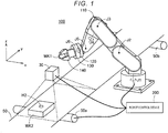
- Fig. 1 is a perspective view of a robot system in a first embodiment.
- the robot system includes a camera 30, a transport device 50, a robot 100, and a robot control device 200.
- the robot 100 and the robot control device 200 are communicably connected via a cable or radio.
- the robot 100 is a single arm robot that is used by attaching various end effectors on an arm flange 120 at a tip end of an arm 110.
- the arm 110 has six joints J1 to J6.
- the joints J2, J3, and J5 are bending joints and the joints J1, J4, and J6 are twisting joints.
- Various end effectors for performing work such as gripping and processing on an object (workpiece) are installed on the arm flange 120 at the tip end of the joint J6.
- a point in a vicinity of the tip end of the arm 110 can be set as a tool center point (TCP).
- TCP is a position used as a reference of the positions of the end effectors, and can be set at any position.
- a predetermined position on a rotation axis of the joint J6 can be set as the TCP.
- a six-axis robot is used, but a robot having another joint mechanism may be used.
- the robot 100 can set the end effectors at any positions in any orientations within a movable range of the arm 110.
- a force detector 130 and an end effector 140 are installed on the arm flange 120.
- the end effector 140 is a gripper, but any other type of end effector can be used.
- the force detector 130 is a six-axis sensor that measures three-axis force acting on the end effector 140 and torque acting around the three axes.
- the force detector 130 measures magnitude of force parallel to three measurement axes orthogonal to each other in a sensor coordinate system which is a unique coordinate system, and the magnitude of torque around the three measurement axes.
- a force sensor as a force detector may be provided at any one or more joints J1 to J5 other than the joint J6.
- the force detector may only measure the force and torque in a direction of control, and a unit for directly measuring the force and torque like the force detector 130 or a unit for measuring the torque of the joint of the robot to obtain the force and the torque indirectly may be used.
- the force detector may measure the force and torque only in the direction of controlling force.
- a coordinate system that defines a space in which the robot 100 is installed is called a robot coordinate system.
- a robot coordinate system is a rectangular coordinate system in three dimensions defined by an x axis and a y axis orthogonal to each other on a horizontal plane and a z axis with an upward vertical direction as a positive direction.
- the rotation angle around the x axis is represented by Rx
- the rotation angle around the y axis is represented by Ry
- the rotation angle around the z axis is represented by Rz.
- Any position in the three-dimensional space can be represented by the position in the x, y, and z directions
- any orientation in the three-dimensional space can be represented by the rotation angle in the Rx, Ry, and Rz directions.
- position it may also mean position and orientation.
- force it may also mean force and torque.
- a workpiece WK2 is transported by the transport device 50.
- the transport device 50 includes transport rollers 50a and 50b.
- the transport device 50 can transport the workpiece WK2 placed on a transport surface by moving the transport surface by rotating these transport rollers 50a and 50b.
- the camera 30 is installed above the transport device 50.
- the camera 30 is installed such that the workpiece WK2 on the transport surface is in the visual field.
- a fitting hole H2 is formed on a surface of the workpiece WK2.
- the end effector 140 can perform work of fitting a workpiece WK1 gripped by the end effector 140 into the fitting hole H2 of the workpiece WK2.
- the fitting work may be performed in a state in which the transport surface is stopped, or, may be executed while moving the transport surface.
- the transport device 50 and the camera 30 can be omitted.
- the robot control device 200 controls the arm 110, the end effector 140, the transport device 50, and the camera 30.
- the functions of the robot control device 200 are realized, for example, by a computer with a processor and a memory executing a computer program.
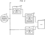
- Fig. 2 is a conceptual diagram showing an example in which a control device of a robot is constituted by a plurality of processors.
- personal computers 400 and 410 and a cloud service 500 provided via a network environment such as LAN are illustrated in addition to the robot 100 and the control device 200 thereof.
- Each of the personal computers 400 and 410 includes a processor and a memory.
- a processor and a memory can be used in the cloud service 500.
- the control device of the robot 100 can be realized by using some or all of a plurality of these processors.
- Fig. 3 is a conceptual diagram showing another example of a control device of a robot constituted by a plurality of processors. This example is different from Fig. 2 in that the control device 200 of the robot 100 is stored in the robot 100. The control device of the robot 100 can also be realized by using some or all of a plurality of these processors in this example.
- Fig. 4 is a block diagram showing functions of the control device 200.
- the control device 200 includes a processor 210, a memory 220, a display device 260, and an input device 270.
- the memory 220 includes a main memory and a non-volatile memory.
- the processor 210 realizes functions of a robot control program creation unit 240 and a control execution unit 250 by executing a program instruction 222 stored in the memory 220 in advance.
- the robot control program creation unit 240 includes a display control unit 242 and a conversion unit 244.
- the display control unit 242 displays an input screen (described later) for creating an operation flow of work of the robot 100 on the display device 260.
- the conversion unit 244 converts the operation flow created in the input screen into a control program 224.
- the converted control program 224 is stored in the memory 220.
- the control program 224 may be written in a low level language such as a machine language, or, in a high level language such as a robot language.
- the control execution unit 250 causes the robot 100 to execute an operation of work by executing the control program 224 created as described above.
- the input device 270 is an input device such as a keyboard or a mouse, and the input and setting by a teacher are performed using the input device 270.
- Some or all of the functions of the robot control program creation unit 240 and the control execution unit 250 may be realized by a hardware circuit. The functions of the robot control program creation unit 240 will be described later.
- Fig. 5 is a flowchart showing a procedure for creating a robot control program
- Figs. 6A to 6F are explanatory diagrams of the procedure.
- the process in Fig. 5 starts when the teacher operates an application program for executing the robot control program creation unit 240.
- Fig. 6A shows an example of a window W1 displayed on the display device 260 by the display control unit 242 when the robot control program creation unit 240 is operated.
- the window W1 corresponds to an input screen for creating an operation flow of work including one or more force control operations.
- the window W1 includes the following areas.
- a plurality of areas in the window W1 may or may not be divided into different frames .
- a button BT1 for indicating the start of the procedure for creating the control program of the work is provided on the upper left of the window W1.
- an input screen for starting step S110 in Fig. 5 is displayed on the display device 260 by the display control unit 242.
- the operation of the teacher inputting work parameter into a box on the input screen will be referred to as "input”
- receiving the parameter input by the teacher and changing into an inner value will be referred to as "setting”.
- Fig. 6B shows an example of a window W2 as an input screen for starting step S110.
- the window W2 corresponds to a screen for selecting work from among a plurality of options.
- the title of the window W2 is "new force sequence”.
- Sequence means work represented by an operation flow
- force sequence means work including operations using force control (called “force control operation”).
- the window W2 includes the following areas.
- the procedure proceeds to the procedure of Fig. 6C (Step 2) without using the sequence copy. That is, in Fig. 6B , when the teacher presses the "next" button without inputting a field F23, the display content of the window W2 is changed to Fig. 6C .
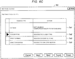
- Fig. 6C the following plurality of types of sequence options are displayed.
- the plurality of options of the sequence shown in Fig. 6C is an example, and any other type of option may be displayed on the input screen.
- the teacher selects the cylinder fitting sequence Sq2 and pushes the "Next" button, the procedure proceeds from step S110 of Fig. 5 to step S120, the input screen for setting work parameters of the work is displayed.
- Fig. 6D shows an example of the display content of the window W2 when performing setting of work parameter in step S120.
- the window W2 is configured as an input screen for setting the planned start position of work and the direction of work as a work parameter of cylindrical fitting and includes the following areas.
- the window W2 at this time is configured as an input screen for setting workpiece information as a work parameter of the cylinder fitting, and includes the following areas.
- the work parameters related to the work set in Figs. 6D and 6E are different from each of the operation parameters included in the work, and are parameters related to the entire operation.
- the operation parameters (described later) in the individual operations included in the work are parameters for individually defining each operation.
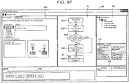
- step S130 of Fig. 5 the operation flow of the work is automatically created and displayed on the display device 260.
- Fig. 6F shows the operation flow of the set work displayed in the first window W1. The following contents are displayed in each area on the window W1.
- Fig. 7 shows an example of a plurality of operation objects which are usable when an operation flow is constituted
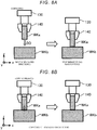
- Figs. 8A to 8D show outlines of operations of some operation objects.
- a plurality of operation objects can be categorized into the following four categories. All of these operations involve force control.
- Contacting is an operation of moving in a designated direction and stopping when receiving reaction force.
- the category of the contacting operation includes a contacting object.
- a workpiece WKa held by the end effector 140 is moved in a designated direction DD and the end effector 140 is stopped when the reaction force is measured by the force detector 130.
- the workpieces WKa and WKb shown in Fig. 8A have no relation to the workpieces WK1 and WK2 shown in Fig. 1 , and are virtual workpieces for describing an outline of an operation. This point is also applied to Figs. 8B to Fig. 8D described later.
- Copying is an operation of maintaining the state in which the force of a designated axis becomes zero.
- the category of the copying operation includes the following three types of operation objects.
- Probing is an operation of probing a position where the force of the designated direction becomes zero.
- the category of the probing operation includes the following two types of operation objects.
- Pressing is an operation of pressing with designated force in the designated direction.
- the category of the pressing operation includes the following two types of operation objects.
- parameters of four objects OB1 to OB4 shown in Fig. 6F for example, the following parameters can be set.
- a parameter defining end condition of an operation and a parameter defining a success determination condition of an operation can be set.
- Threshold value of force 5 N (Operation stops when the force exceeds 5 N.)
- the parameter setting area PR in which the parameters defining the operation, the parameters defining the end condition of the operation, and the parameters defining the success determination condition of the operation can be set, it is possible to easily create a control program including end of operation and success/failure determination. It may be a mode in which it is not possible to set one or both of the parameters defining the end condition of the operation, the parameters defining the success determination condition of the operation.
- an alarm mark AL is displayed with respect to the fourth operation object OB4.
- the alarm mark AL is a mark displayed when an unacceptable parameter value is included in the parameters set in the parameter setting area PR with respect to the operation object OB4. Items and values of the defective parameters may be displayed when the mouse pointer is moved over the alarm mark AL.
- the teacher sees the alarm mark AL, since the teacher knows that there is a deficiency in the parameter of the operation object OB4, the deficiency in the parameter can be corrected.
- An alarm or an error may be displayed at another position in the screen instead of displaying the alarm mark AL in the operation object OB.
- alarms or errors may be displayed in the tree of the sequence display area SQ, or, alarms or errors related to the same operation object OB may be displayed at a plurality of positions.
- an alarm or an error may be displayed.
- the display of an alarm or an error of such work parameter may be displayed in, for example, the tree of the sequence display area SQ.
- the end condition or the success determination condition of the operation parameter can be set to include a condition of executing determination based on the frequency of the force measured in the force detector 130.
- Fig. 9 is a graph showing an example of change in force F measured by the force detector 130.
- the force F vibrates during a period PP after 0.5 seconds from the start of the operation.
- Such a vibration can be an effect of a peripheral device (for example, operation of conveyor).
- the control device 200 may execute frequency analysis of temporal change of the force F, and the detection of the power spectrum of the frequency designated in advance being equal to or lower than the threshold value or equal to or higher than the threshold value may be used as a part of the end condition or the success determination condition.
- Fig. 10 is an explanatory diagram showing an example of the relation between the work parameters set in Figs. 6D and 6E and the operation parameter.
- an example of work parameters displayed in the parameter setting area PR on the window W1 ( Fig. 6F ) is shown. These work parameters are, for example, displayed in the parameter setting area PR by selecting the sequence block SB1 in the operation flow creation area FL. These work parameters are the work parameters set in the input screens of Figs. 6D and 6E .
- a dialog DL1 showing operation parameters influenced by the work parameters is displayed.
- the relationship display button BT of the fitting direction when clicked, it is displayed in the dialog DL1 that the fitting direction affects the contacting direction of contacting operation, the pressing direction of the pressing and probing operation, the moving direction of the pressing and moving operation, and the force control in the six axes directions.
- the teacher can check the relationship between the work parameters and the operation parameters of each operation from the dialog DL1.
- the operation parameter of the force control operation automatically set from the work parameter is not limited to the direction of force control, and other operation parameters may be automatically set according to the work parameter.
- the moving amount while pressing of the pressing and moving operation (moving amount in the -Z direction at the right end of Fig. 8D ) may be automatically set from workpiece information (for example, fitting depth) of the work parameter.
- workpiece information for example, fitting depth
- an automatic setting mode of the parameter one mode may be selected from a first mode in which only the work parameter can be changed, a second mode in which only the operation parameter can be changed, and a third mode in which both of the work parameter and the operation parameter can be changed. In this way, a novice can create a work sequence using only the work parameter, and an expert can perform further detailed corrections using the operation parameter.
- the operation parameter is edited with the work parameter as correct.
- the robot 100 When the operation flow of the work is created as shown in Fig. 6F , it is possible to cause the robot 100 to execute the work according to the operation flow.
- the conversion unit 244 ( Fig. 4 ) converts the operation flow into a control program, and the control execution unit 250 causes the robot 100 to execute the work by executing the control program. This corresponds to a trial of the control program.
- Fig. 11A is an explanatory diagram showing an example of a screen showing a result of work executed according to an operation flow.
- an execution stop mark SM is set in the third operation object OB3 in the operation flow creation area FL.
- the execution stop mark SM means temporarily stopping the execution in the operation object OB3.
- the execution stop mark SM can be set, for example, using the context menu of each operation object.
- the context menu is a menu displayed by right-clicking the mouse.
- the temporal change of the force Fx in the X axis direction and the torque Tx around the X axis are displayed among the plurality of force measured by the force detector 130 at the time of executing the operation flow.
- the main view area MV it is possible to select and display any one or more temporal change of force of the plurality of force measured by the force detector 130. It is also possible to display the temporal change of the measured position of the TCP and the temporal change of the difference between the target position and the measured position of the TCP on the main view area MV.
- the period of displaying the result in the main view area MV can be an operation period of any one of the operation objects in the operation flow, or can be the entire period from the start to stop of the execution.
- the execution result of the operation period of the operation object is displayed.
- the sequence block SB1 is selected, the result of the entire period from the start to stop of the execution is displayed.
- the period of displaying result in the main view area MV may be an operation period over a plurality of continuing operation objects.
- the information of some execution results of the control program is also displayed in the result area RS.
- Other types of results than the one shown in Fig. 11A may be displayed in the main view area MV.
- information related to the robot such as the speed and the angle of each joint of the robot may be displayed.
- the window W1 is further configured to include a field or a button for saving the data as the executed result in a desired place.
- the data storage destination may be within the robot control device 200, or in the computer or the cloud connected to the robot control device 200.
- the data format may be a database or a file format.
- the teacher can observe the execution result of the control program and adjust the parameters of individual objects as necessary.
- the adjustment can be executed by changing the parameters of the object displayed in the parameter setting area PR in the state where any one of the objects OB1 to OB4 in the operation flow creation area FL is selected.
- the parameters of the contacting object are adjusted so as to lower the speed in the contacting operation.
- Fig. 11B shows an example of the result re-executing the control program after the adjustment of the parameters.
- the peaks of the force Fnew and Tnew after the adjustment are lower than the peaks of the force Fold and Told before the adjustment.
- the window W1 since it is possible to perform a trial of the adjustment of the parameters of the object of the operation flow generated in the operation flow creation area FL and the work according to the operation flow, an operation flow that runs appropriately can be easily created. However, such adjustment and trial processes may be omitted.
- Fig. 11A in the case where the data of the past execution result is saved, it is also possible to display the past data.
- the conversion unit 244 converts the operation flow into a control program according to the indication of the teacher in step S140 in Fig. 5 .
- the indication can be performed, for example, by selecting "create control program" from the context menu of the operation flow creation area FL. It is preferable that any one method of the following three types of methods can be selectively performed for the conversion from the operation flow to a control program and execution.
- Fig. 12 shows an example of a window W3 as an input screen displayed when the operation flow is converted into a control program according to the indication of the teacher.
- This window W3 includes a sequence selecting area F31 for selecting a sequence (that is an operation flow) to be converted into a control program and a program file name setting area F32 for setting the file name of the control program.
- the sequence selecting area F31 may be omitted.
- the window W3 may be configured to include an area for designating information such as a storage destination of parameters.
- the operation flow is converted into a control program by the conversion unit 244, and the control program is stored in the memory 220.
- step S150 of Fig. 5 the robot control device 200 controls the robot and causes the robot to execute the work according to the control program created in step S140.
- This work can be executed as a checking work for checking the operations of the robot 100 on the production line or an original work for manufacturing a product on the production line.
- a screen for setting the work parameter of the selected work Figs. 6D and 6E
- a screen Fig. 6F
- displays the operation flow of the work in an editable manner so that the operation flow of the work can be easily generated. Since some of the operation parameters of the force control operation are automatically set from the work parameter set for the selected work, the teacher can easily create the control program.
- Fig. 13A shows a display example of operation parameters in the case where a six-axis force sensor is used as the force detector 130.
- a six-axis force sensor is used as the force detector 130.
- the force control directions and the setting values are displayed in a portion of the parameter setting area PR ( Fig. 6F ) with respect to the pressing operation.
- the six-axis force sensor it is possible to designate what kind of force control is to be executed for all the force of the six axes (force Fx, Fy, and Fz of three axes and torques Tx, Ty, and Tz around three axes).
- Fig. 13B shows a display example of operation parameters in the case of using a three-axis force sensor as the force detector 130.
- the three-axis force sensor it is possible to designate what kind of force control is to be executed for the force Fx, Fy, and Fz detectable with a three-axis sensor.
- the force tilt Tx, Ty, and Tz around three axes
- a method of setting the parameters in the setting disabled state is, as shown in Fig. 13B , not to display the parameters on the input screen.
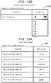
- Fig. 14A shows another display example of operation parameters in the case of using the six-axis force sensor as the force detector 130.
- the contacting direction force control direction
- the setting values are displayed in a portion of the parameter setting area PR with respect to the contacting operation.
- any one direction can be selected from the directions X, Y, Z, U, V, and W of the force of six axes, and either a positive direction or a negative direction can be selected for each direction.
- the directions U, V, and W mean the directions of the torques Tx, Ty, and Tz.
- Fig. 14B shows a display example of operation parameters in the case of using the three-axis force sensor as the force detector 130.
- any one direction can be selected from the directions X, Y, and Z of force detectable with the three-axis sensor, and either a positive direction or a negative direction can be selected for each direction.
- the force tilt Tx, Ty, and Tz around three axes
- Fig. 15A is an explanatory diagram of a display example of operation parameters suitable for the six-axis robot.
- an example in which the force control directions and the setting values are displayed in a portion of the parameter setting area PR ( Fig. 6F ) with respect to the pressing operation is shown.
- Fig. 15B shows a display example of operation parameters suitable for a SCARA robot which is a four-axis robot.
- SCARA robot In the case of using the SCARA robot, it is possible to designate what kind of force control is to be executed for the directions of four axes controllable by the SCARA robot. On the other hand, for the directions uncontrollable by the SCARA robot, it is preferable to set the state of those parameters to a setting disabled state.
- Fig. 16A shows another display example of operation parameters suitable for the six-axis robot.
- the contacting direction force control direction
- the setting values are displayed in a portion of the parameter setting area PR with respect to the contacting operation.
- any one direction can be selected from the directions X, Y, Z, U, V, and W of the force of six axes, and either a positive direction or a negative direction can be selected for each direction.
- Fig. 16B shows another display example of operation parameters suitable for the SCARA robot with four axes.
- any one direction can be selected from the directions X, Y, Z, and U of the force of four axes controllable by the SCARA robot, and either a positive direction or a negative direction can be selected for each direction.
- the directions uncontrollable by the SCARA robot it is preferable to set the state of those parameters to a setting disabled state.
- the teacher if the unnecessary parameters are set in the setting disabled state according to the type of the robot and the type of the sensor (force detector) connected to the robot control device 200, it is possible for the teacher to easily set only necessary parameters .
- the limitation on the display and input of the operation parameters according to the type of the robot and the limitation on the display and input of the parameters according to the type of the force detector are different, severer limitations are applied.
- the types of the sensor not only the force detector 130 but also other types of sensors such as the types of the camera 30 (for example, either a monocular camera or a stereo camera) may be used.
- Fig. 17A is an explanatory diagram showing an example of input prohibition of operation parameters.
- the shape of the "probing route" and the dimensions thereof are displayed in the parameter setting area PR.
- the shape of the "probing route” is set to be a spiral, and the diameter and the pitch value of the spiral are set as the dimension.
- the parameters (moving distance in X, Y, Z directions) in the case where the "probing route" is not a spiral among the parameters present in the parameter setting area PR are in the setting disabled state (here, grayout state).
- Fig. 17B is an explanatory diagram showing another example of input prohibition of operation parameters.
- the shape of the "probing route" is set to be a straight line, and the values of the moving distances in the X, Y, and Z directions are set as the dimensions.
- the parameters in the case where the "probing route" is not a straight line (diameter and pitch of spiral) are in the setting disabled state (grayout state) .
- Figs. 17A and 17B when there is an unnecessary parameter according to the parameters set for a certain operation object, and the state of the parameter is changed to the setting disabled state, it is possible for the teacher to easily set only necessary parameters.
- other work parameters may be set in the setting disabled state according to the work parameters, or a specific operation parameter may be set in the setting disabled state according to a certain work parameter.
- Fig. 18 is an explanatory diagram showing a setting example of an interruption permission timing of work in still another embodiment.
- the parameter setting area PR at the upper left of Fig. 18 two interruption permission timings of "interruption during operation” and "interruption after operation” are displayed as work parameters.
- an interruption permission timing setting dialogue DL3 is opened, and setting values of the interruption permission timing related to each operation in the work will be displayed.
- the interruption permission timing related to each operation may be set in the dialogue DL3, or, one of the operation objects may be selected in the operation flow creation area FL ( Fig. 6F ) and set as the operation parameter of the work in the parameter setting area PR.
- the permission and non-permission of "interruption during operation”, and the permission and non-permission of "interruption after operation” mean the following settings S1e, S1n, S2e, and S2n, respectively.
- the temporary stop signal is a signal for requesting a temporary stop of the work of the robot 100, and for example, a signal from a sensor detecting that a safety door is opened, a sensor detecting that a person is approaching, or the like.
- interruption permission timing is set for each of the four objects OB1 to OB4.
- Such an interruption permission timing is set in order to interrupt the work at an appropriate timing suitable for the content of the operation in the work when a temporary stop signal is generated during the work. For example, if the work of the polishing operation is interrupted when the temporary stop signal is received during the polishing operation, polishing unevenness occurs. For example, if non-permission is set for "interruption during operation" for the operations executing polishing (pressing and moving operation), and permission is set for "interruption after operation", the work of the polishing operation is not interrupted until the end, so that it is possible to prevent occurrence of defects such as polishing unevenness.
- the interruption permission timing can be appropriately set.
- Such setting of the interruption permission timing is difficult to set in the case of directly inputting the control program of the robot, but there is an advantage that it is comparatively easy to perform setting in the case of setting content of work using an operation flow (sequence) including one or more operation objects.
- Fig. 19A shows a setting example in a mode in which it is possible to set both "interruption during operation” and "interruption after operation".
- the determination of interrupting the work in the mode is the same as the content of the above-described settings S1e, S1n, S2e, and S2n.
- S1e, S1n, S2e, and S2n In the case where none of the interruption permission timing on the final operation D in the operation flow is set as permission, and a temporary stop signal is received during the operation D, it is preferable that the operation of the robot 100 is stopped at the end of the final operation D.
- Fig. 19B shows a setting example in a mode where only "interruption during operation" can be set.
- the determination of interrupting the work in the mode is the same as the content of the above-described settings S1e and S1n.
- Fig. 19C shows a setting example in the mode where only "interruption after operation" can be set.
- the determination of interrupting the work in the mode is the same as the content of the above-described settings S2e and S2n.
- the setting of the interruption permission timing is possible for the force control operations during the work, it is possible to execute the interruption of the work at a preferable timing when the robot control device 200 receives the temporary stop signal from the outside. Accordingly, it is possible to easily create a control program capable of reducing the possibility of occurrence of defections such as product defection.
- a screen may be configured so that a time-out can be set for work. For example, even in a case of continuing work and when the work continues for more than the designated time-out time in advance, the work may be interrupted at that point in time.
Landscapes
- Engineering & Computer Science (AREA)
- Robotics (AREA)
- Mechanical Engineering (AREA)
- Human Computer Interaction (AREA)
- Physics & Mathematics (AREA)
- General Physics & Mathematics (AREA)
- Automation & Control Theory (AREA)
- Manufacturing & Machinery (AREA)
- Software Systems (AREA)
- Manipulator (AREA)
- Numerical Control (AREA)
Applications Claiming Priority (1)
| Application Number | Priority Date | Filing Date | Title |
|---|---|---|---|
| JP2018011355A JP6973119B2 (ja) | 2018-01-26 | 2018-01-26 | ロボット制御装置及びロボットシステム |
Publications (2)
| Publication Number | Publication Date |
|---|---|
| EP3517255A2 true EP3517255A2 (de) | 2019-07-31 |
| EP3517255A3 EP3517255A3 (de) | 2020-01-22 |
Family
ID=65228437
Family Applications (1)
| Application Number | Title | Priority Date | Filing Date |
|---|---|---|---|
| EP19153471.8A Pending EP3517255A3 (de) | 2018-01-26 | 2019-01-24 | Robotersteuerungsvorrichtung, robotersystem und verfahren zur erstellung eines steuerungsprogramms |
Country Status (4)
| Country | Link |
|---|---|
| US (1) | US20190232492A1 (de) |
| EP (1) | EP3517255A3 (de) |
| JP (1) | JP6973119B2 (de) |
| CN (1) | CN110076751B (de) |
Families Citing this family (17)
| Publication number | Priority date | Publication date | Assignee | Title |
|---|---|---|---|---|
| JP7069747B2 (ja) | 2018-01-26 | 2022-05-18 | セイコーエプソン株式会社 | ロボット制御装置及びロボットシステム |
| JP7087632B2 (ja) * | 2018-04-26 | 2022-06-21 | セイコーエプソン株式会社 | ロボット制御装置 |
| US10576526B2 (en) * | 2018-07-03 | 2020-03-03 | Komatsu Industries Corporation | Workpiece conveying system, and workpiece conveying method |
| WO2020200468A1 (en) * | 2019-04-05 | 2020-10-08 | Abb Schweiz Ag | System for optimizing robot performance |
| JP7260002B2 (ja) * | 2020-01-16 | 2023-04-18 | オムロン株式会社 | 制御装置、制御方法、及び制御プログラム |
| JP7563117B2 (ja) * | 2020-10-30 | 2024-10-08 | セイコーエプソン株式会社 | ロボット制御方法およびロボットシステム |
| JP7619037B2 (ja) * | 2020-12-21 | 2025-01-22 | セイコーエプソン株式会社 | プログラム作成支援方法、プログラム作成支援装置、プログラム作成支援プログラム及び記憶媒体 |
| CN113009874B (zh) * | 2021-02-18 | 2022-12-09 | 西门子工厂自动化工程有限公司 | 拧丝实验设备控制方法、装置、电子设备和介质 |
| JP2023004016A (ja) * | 2021-06-25 | 2023-01-17 | セイコーエプソン株式会社 | プログラム作成装置およびプログラム |
| JP2023004015A (ja) * | 2021-06-25 | 2023-01-17 | セイコーエプソン株式会社 | プログラム作成装置、プログラムおよびロボット動作プログラム |
| JP2023007084A (ja) * | 2021-07-01 | 2023-01-18 | セイコーエプソン株式会社 | 力制御パラメーター設定支援方法および力制御パラメーター設定支援システム |
| JP7666223B2 (ja) * | 2021-08-18 | 2025-04-22 | 新東工業株式会社 | 自動塗布装置、及び自動塗布方法 |
| DE102021210750B3 (de) * | 2021-09-27 | 2022-08-04 | OPTIMA pharma GmbH | Verfahren und Vorrichtung zur Behebung von Störungen in einer Füll- und/oder Verschließ- und/oder Nachverarbeitungsanlage |
| JP2023112867A (ja) * | 2022-02-02 | 2023-08-15 | セイコーエプソン株式会社 | 生成方法、コンピュータープログラム、および、生成システム |
| JP7799275B2 (ja) | 2022-03-04 | 2026-01-15 | 新東工業株式会社 | ロボット、及び、その制御方法 |
| US20240001551A1 (en) * | 2022-06-02 | 2024-01-04 | Worcester Polytechnic Institute | Autonomous robotic assembly of arbitrary part shapes |
| WO2024176466A1 (ja) * | 2023-02-24 | 2024-08-29 | ファナック株式会社 | 制御装置及びロボットシステム |
Citations (1)
| Publication number | Priority date | Publication date | Assignee | Title |
|---|---|---|---|---|
| JP2014233814A (ja) | 2013-06-04 | 2014-12-15 | 株式会社安川電機 | ロボット教示補助装置、ロボットシステムおよびロボット教示方法 |
Family Cites Families (8)
| Publication number | Priority date | Publication date | Assignee | Title |
|---|---|---|---|---|
| JP3486903B2 (ja) * | 1999-09-06 | 2004-01-13 | 日邦プレシジョン株式会社 | 装置の動作手順作成システム及びその動作手順が記録された記録媒体並びに制御システム |
| US6993456B2 (en) * | 1999-09-30 | 2006-01-31 | Rockwell Automation Technologies, Inc. | Mechanical-electrical template based method and apparatus |
| US7860609B2 (en) * | 2005-05-06 | 2010-12-28 | Fanuc Robotics America, Inc. | Robot multi-arm control system |
| DE102010012598A1 (de) * | 2010-02-26 | 2011-09-01 | Kuka Laboratories Gmbh | Prozessmodulbibliothek und Programmierumgebung zur Programmierung eines Manipulatorprozesses |
| JP5962590B2 (ja) * | 2013-05-31 | 2016-08-03 | 株式会社安川電機 | ロボットシステムおよび被加工物の製造方法 |
| JP5850004B2 (ja) * | 2013-08-09 | 2016-02-03 | 株式会社安川電機 | ロボット制御装置及びロボット制御方法 |
| JP6460690B2 (ja) * | 2014-09-16 | 2019-01-30 | キヤノン株式会社 | ロボット装置、ロボット制御方法、プログラム及び記録媒体 |
| KR102603939B1 (ko) * | 2015-07-08 | 2023-11-20 | 유니버셜 로보츠 에이/에스 | 제3자 기여를 가진 산업용 로봇의 최종 사용자 프로그래밍 확장 방법 |
-
2018
- 2018-01-26 JP JP2018011355A patent/JP6973119B2/ja active Active
-
2019
- 2019-01-24 EP EP19153471.8A patent/EP3517255A3/de active Pending
- 2019-01-24 CN CN201910070913.3A patent/CN110076751B/zh active Active
- 2019-01-25 US US16/257,256 patent/US20190232492A1/en not_active Abandoned
Patent Citations (1)
| Publication number | Priority date | Publication date | Assignee | Title |
|---|---|---|---|---|
| JP2014233814A (ja) | 2013-06-04 | 2014-12-15 | 株式会社安川電機 | ロボット教示補助装置、ロボットシステムおよびロボット教示方法 |
Non-Patent Citations (1)
| Title |
|---|
| BISCHOFF R ET AL: "The MORPHA style guide for icon-based programming", ROBOT AND HUMAN INTERACTIVE COMMUNICATION, 2002. PROCEEDINGS. 11TH IEE E INTERNATIONAL WORKSHOP ON SEPT. 25-27, 2002, PISCATAWAY, NJ, USA,IEEE, 25 September 2002 (2002-09-25), pages 482 - 487, XP010611690, ISBN: 978-0-7803-7545-1 * |
Also Published As
| Publication number | Publication date |
|---|---|
| US20190232492A1 (en) | 2019-08-01 |
| JP2019126894A (ja) | 2019-08-01 |
| CN110076751B (zh) | 2024-02-13 |
| EP3517255A3 (de) | 2020-01-22 |
| CN110076751A (zh) | 2019-08-02 |
| JP6973119B2 (ja) | 2021-11-24 |
Similar Documents
| Publication | Publication Date | Title |
|---|---|---|
| EP3517255A2 (de) | Robotersteuerungsvorrichtung, robotersystem und verfahren zur erstellung eines steuerungsprogramms | |
| US11167417B2 (en) | Robot control device and robot system | |
| US11389954B2 (en) | Robot control device | |
| JP7067107B2 (ja) | ロボット制御装置及びロボットシステム | |
| JP4235214B2 (ja) | ロボットプログラムを作成するための装置、プログラム、記録媒体及び方法 | |
| JP6698268B2 (ja) | ロボット | |
| US10656618B2 (en) | Numerical controller | |
| JP4940715B2 (ja) | ピッキングシステム | |
| US20230330802A1 (en) | Flaw grinding system, flaw grinding method, and steel-product manufacturing method employing the flaw grinding method | |
| US11740062B2 (en) | Control device, measurement system, and measurement method | |
| US20050256606A1 (en) | Method in the control of a machine tool cell | |
| US20230241763A1 (en) | Generation Method, Computer Program, And Generation System | |
| EP0477430B1 (de) | Off-line-Lernverfahren für industriellen Roboter | |
| JP3450609B2 (ja) | ロボットのオフライン教示装置 | |
| JP3560216B2 (ja) | 作業支援装置 | |
| Antonelli et al. | FREE: flexible and safe interactive human-robot environment for small batch exacting applications | |
| JPH06134684A (ja) | ロボット軌道を教示するための方法 | |
| CN114549821A (zh) | 视觉模板生成、目标检测方法和装置及机器人系统 | |
| JP2002361581A (ja) | 作業自動化装置、作業自動化方法およびその方法を記憶した記憶媒体 | |
| JP2686158B2 (ja) | データ演算入力機能を有する数値制御装置 | |
| Sarida et al. | Human-robot interaction for robotic inspections based on mixed reality | |
| Dario Antonelli et al. | FREE: Flexible and Safe Interactive Human-Robot Environment for Small Batch Exacting Applications | |
| JPH04286004A (ja) | 教示点データ作成装置 | |
| JPS61168013A (ja) | 図形情報のタブレツト入力方式 | |
| JPH0784618A (ja) | ロボットの座標系設定方法 |
Legal Events
| Date | Code | Title | Description |
|---|---|---|---|
| PUAI | Public reference made under article 153(3) epc to a published international application that has entered the european phase |
Free format text: ORIGINAL CODE: 0009012 |
|
| STAA | Information on the status of an ep patent application or granted ep patent |
Free format text: STATUS: THE APPLICATION HAS BEEN PUBLISHED |
|
| AK | Designated contracting states |
Kind code of ref document: A2 Designated state(s): AL AT BE BG CH CY CZ DE DK EE ES FI FR GB GR HR HU IE IS IT LI LT LU LV MC MK MT NL NO PL PT RO RS SE SI SK SM TR |
|
| AX | Request for extension of the european patent |
Extension state: BA ME |
|
| RIC1 | Information provided on ipc code assigned before grant |
Ipc: B25J 9/16 20060101AFI20190730BHEP Ipc: G05B 19/409 20060101ALI20190730BHEP |
|
| PUAL | Search report despatched |
Free format text: ORIGINAL CODE: 0009013 |
|
| AK | Designated contracting states |
Kind code of ref document: A3 Designated state(s): AL AT BE BG CH CY CZ DE DK EE ES FI FR GB GR HR HU IE IS IT LI LT LU LV MC MK MT NL NO PL PT RO RS SE SI SK SM TR |
|
| AX | Request for extension of the european patent |
Extension state: BA ME |
|
| RIC1 | Information provided on ipc code assigned before grant |
Ipc: B25J 9/16 20060101AFI20191218BHEP Ipc: G05B 19/409 20060101ALI20191218BHEP |
|
| STAA | Information on the status of an ep patent application or granted ep patent |
Free format text: STATUS: REQUEST FOR EXAMINATION WAS MADE |
|
| 17P | Request for examination filed |
Effective date: 20200617 |
|
| RBV | Designated contracting states (corrected) |
Designated state(s): AL AT BE BG CH CY CZ DE DK EE ES FI FR GB GR HR HU IE IS IT LI LT LU LV MC MK MT NL NO PL PT RO RS SE SI SK SM TR |
|
| STAA | Information on the status of an ep patent application or granted ep patent |
Free format text: STATUS: EXAMINATION IS IN PROGRESS |
|
| 17Q | First examination report despatched |
Effective date: 20220103 |