EP3517508A1 - Procédé de traitement de décharge de liquide zéro pour récupérer de l'eau à partir d'un effluent liquide contaminé en vue de sa réutilisation ultérieure - Google Patents
Procédé de traitement de décharge de liquide zéro pour récupérer de l'eau à partir d'un effluent liquide contaminé en vue de sa réutilisation ultérieure Download PDFInfo
- Publication number
- EP3517508A1 EP3517508A1 EP18195919.8A EP18195919A EP3517508A1 EP 3517508 A1 EP3517508 A1 EP 3517508A1 EP 18195919 A EP18195919 A EP 18195919A EP 3517508 A1 EP3517508 A1 EP 3517508A1
- Authority
- EP
- European Patent Office
- Prior art keywords
- water
- stage
- osmosis
- liquid discharge
- salts
- Prior art date
- Legal status (The legal status is an assumption and is not a legal conclusion. Google has not performed a legal analysis and makes no representation as to the accuracy of the status listed.)
- Withdrawn
Links
- XLYOFNOQVPJJNP-UHFFFAOYSA-N water Substances O XLYOFNOQVPJJNP-UHFFFAOYSA-N 0.000 title claims abstract description 89
- 238000000034 method Methods 0.000 title claims abstract description 58
- 239000007788 liquid Substances 0.000 title claims abstract description 55
- 230000008569 process Effects 0.000 title claims abstract description 53
- 238000011282 treatment Methods 0.000 title claims abstract description 41
- 208000028659 discharge Diseases 0.000 title claims abstract description 40
- 239000012528 membrane Substances 0.000 claims abstract description 56
- 238000001223 reverse osmosis Methods 0.000 claims abstract description 48
- 238000011084 recovery Methods 0.000 claims abstract description 38
- 238000009292 forward osmosis Methods 0.000 claims abstract description 36
- 238000005516 engineering process Methods 0.000 claims abstract description 32
- 150000003839 salts Chemical class 0.000 claims abstract description 26
- 238000010612 desalination reaction Methods 0.000 claims abstract description 25
- 239000007787 solid Substances 0.000 claims abstract description 21
- 238000007791 dehumidification Methods 0.000 claims abstract description 16
- 238000001556 precipitation Methods 0.000 claims abstract description 16
- 239000002351 wastewater Substances 0.000 claims abstract description 16
- 238000001704 evaporation Methods 0.000 claims abstract description 10
- 230000008020 evaporation Effects 0.000 claims abstract description 10
- 230000000737 periodic effect Effects 0.000 claims abstract description 7
- 238000004140 cleaning Methods 0.000 claims abstract description 6
- 239000012141 concentrate Substances 0.000 claims description 23
- 239000002244 precipitate Substances 0.000 claims description 11
- 230000015572 biosynthetic process Effects 0.000 claims description 8
- 238000004519 manufacturing process Methods 0.000 claims description 8
- 238000005065 mining Methods 0.000 claims description 4
- 230000003204 osmotic effect Effects 0.000 claims description 3
- 238000010926 purge Methods 0.000 claims description 3
- 229910000831 Steel Inorganic materials 0.000 claims 1
- 239000010959 steel Substances 0.000 claims 1
- 239000000243 solution Substances 0.000 description 24
- HPALAKNZSZLMCH-UHFFFAOYSA-M sodium;chloride;hydrate Chemical compound O.[Na+].[Cl-] HPALAKNZSZLMCH-UHFFFAOYSA-M 0.000 description 21
- 239000012267 brine Substances 0.000 description 19
- 230000008901 benefit Effects 0.000 description 10
- 239000013505 freshwater Substances 0.000 description 10
- 239000012535 impurity Substances 0.000 description 10
- OKTJSMMVPCPJKN-UHFFFAOYSA-N Carbon Chemical compound [C] OKTJSMMVPCPJKN-UHFFFAOYSA-N 0.000 description 9
- 238000000605 extraction Methods 0.000 description 7
- 238000001914 filtration Methods 0.000 description 7
- 150000002500 ions Chemical class 0.000 description 7
- 239000012466 permeate Substances 0.000 description 7
- 239000000047 product Substances 0.000 description 7
- 230000011514 reflex Effects 0.000 description 7
- RYGMFSIKBFXOCR-UHFFFAOYSA-N Copper Chemical compound [Cu] RYGMFSIKBFXOCR-UHFFFAOYSA-N 0.000 description 6
- 229910052802 copper Inorganic materials 0.000 description 6
- 239000010949 copper Substances 0.000 description 6
- 230000004907 flux Effects 0.000 description 6
- 230000009467 reduction Effects 0.000 description 6
- 239000000126 substance Substances 0.000 description 6
- 241000243142 Porifera Species 0.000 description 5
- FAPWRFPIFSIZLT-UHFFFAOYSA-M Sodium chloride Chemical compound [Na+].[Cl-] FAPWRFPIFSIZLT-UHFFFAOYSA-M 0.000 description 5
- 238000013461 design Methods 0.000 description 5
- 238000005265 energy consumption Methods 0.000 description 5
- 238000009434 installation Methods 0.000 description 5
- 230000002829 reductive effect Effects 0.000 description 5
- 239000011780 sodium chloride Substances 0.000 description 5
- 238000004065 wastewater treatment Methods 0.000 description 5
- 239000003643 water by type Substances 0.000 description 5
- BUGBHKTXTAQXES-UHFFFAOYSA-N Selenium Chemical compound [Se] BUGBHKTXTAQXES-UHFFFAOYSA-N 0.000 description 4
- 239000000356 contaminant Substances 0.000 description 4
- 238000002425 crystallisation Methods 0.000 description 4
- 230000008030 elimination Effects 0.000 description 4
- 238000003379 elimination reaction Methods 0.000 description 4
- 238000012545 processing Methods 0.000 description 4
- 229910052711 selenium Inorganic materials 0.000 description 4
- 239000011669 selenium Substances 0.000 description 4
- XEEYBQQBJWHFJM-UHFFFAOYSA-N Iron Chemical compound [Fe] XEEYBQQBJWHFJM-UHFFFAOYSA-N 0.000 description 3
- 238000003723 Smelting Methods 0.000 description 3
- 229910052793 cadmium Inorganic materials 0.000 description 3
- BDOSMKKIYDKNTQ-UHFFFAOYSA-N cadmium atom Chemical compound [Cd] BDOSMKKIYDKNTQ-UHFFFAOYSA-N 0.000 description 3
- 239000002041 carbon nanotube Substances 0.000 description 3
- 229910021393 carbon nanotube Inorganic materials 0.000 description 3
- 239000012159 carrier gas Substances 0.000 description 3
- 238000000975 co-precipitation Methods 0.000 description 3
- 239000000428 dust Substances 0.000 description 3
- 230000007613 environmental effect Effects 0.000 description 3
- 239000002245 particle Substances 0.000 description 3
- 238000005498 polishing Methods 0.000 description 3
- 229920006395 saturated elastomer Polymers 0.000 description 3
- 238000004062 sedimentation Methods 0.000 description 3
- 238000000108 ultra-filtration Methods 0.000 description 3
- 239000002699 waste material Substances 0.000 description 3
- 241000446313 Lamella Species 0.000 description 2
- VYPSYNLAJGMNEJ-UHFFFAOYSA-N Silicium dioxide Chemical compound O=[Si]=O VYPSYNLAJGMNEJ-UHFFFAOYSA-N 0.000 description 2
- 238000003491 array Methods 0.000 description 2
- 230000033228 biological regulation Effects 0.000 description 2
- 238000009835 boiling Methods 0.000 description 2
- 230000008859 change Effects 0.000 description 2
- 238000006243 chemical reaction Methods 0.000 description 2
- 238000005352 clarification Methods 0.000 description 2
- 238000007865 diluting Methods 0.000 description 2
- 238000009300 dissolved air flotation Methods 0.000 description 2
- 239000003651 drinking water Substances 0.000 description 2
- 235000020188 drinking water Nutrition 0.000 description 2
- 230000000694 effects Effects 0.000 description 2
- 238000005188 flotation Methods 0.000 description 2
- 239000007789 gas Substances 0.000 description 2
- 239000004519 grease Substances 0.000 description 2
- 230000006872 improvement Effects 0.000 description 2
- 230000006698 induction Effects 0.000 description 2
- 229910052742 iron Inorganic materials 0.000 description 2
- 239000000463 material Substances 0.000 description 2
- 238000013327 media filtration Methods 0.000 description 2
- 229910052751 metal Inorganic materials 0.000 description 2
- 239000002184 metal Substances 0.000 description 2
- 238000012856 packing Methods 0.000 description 2
- 230000010287 polarization Effects 0.000 description 2
- 230000002265 prevention Effects 0.000 description 2
- 230000003134 recirculating effect Effects 0.000 description 2
- 238000004064 recycling Methods 0.000 description 2
- 239000013049 sediment Substances 0.000 description 2
- 238000000926 separation method Methods 0.000 description 2
- 125000006850 spacer group Chemical group 0.000 description 2
- 241000894007 species Species 0.000 description 2
- 239000010409 thin film Substances 0.000 description 2
- 230000035899 viability Effects 0.000 description 2
- 241000437284 Andalucia Species 0.000 description 1
- 241000894006 Bacteria Species 0.000 description 1
- ZOXJGFHDIHLPTG-UHFFFAOYSA-N Boron Chemical compound [B] ZOXJGFHDIHLPTG-UHFFFAOYSA-N 0.000 description 1
- MWRWFPQBGSZWNV-UHFFFAOYSA-N Dinitrosopentamethylenetetramine Chemical compound C1N2CN(N=O)CN1CN(N=O)C2 MWRWFPQBGSZWNV-UHFFFAOYSA-N 0.000 description 1
- 210000001956 EPC Anatomy 0.000 description 1
- 239000004952 Polyamide Substances 0.000 description 1
- 239000004695 Polyether sulfone Substances 0.000 description 1
- 229910006130 SO4 Inorganic materials 0.000 description 1
- DWAQJAXMDSEUJJ-UHFFFAOYSA-M Sodium bisulfite Chemical compound [Na+].OS([O-])=O DWAQJAXMDSEUJJ-UHFFFAOYSA-M 0.000 description 1
- 241000700605 Viruses Species 0.000 description 1
- 238000009825 accumulation Methods 0.000 description 1
- 239000002253 acid Substances 0.000 description 1
- 238000010306 acid treatment Methods 0.000 description 1
- 230000002378 acidificating effect Effects 0.000 description 1
- 230000009471 action Effects 0.000 description 1
- 230000002411 adverse Effects 0.000 description 1
- 238000013475 authorization Methods 0.000 description 1
- 229910052788 barium Inorganic materials 0.000 description 1
- 229910052796 boron Inorganic materials 0.000 description 1
- 239000006227 byproduct Substances 0.000 description 1
- 229910052791 calcium Inorganic materials 0.000 description 1
- 229940112112 capex Drugs 0.000 description 1
- 238000009388 chemical precipitation Methods 0.000 description 1
- 239000003795 chemical substances by application Substances 0.000 description 1
- 239000000084 colloidal system Substances 0.000 description 1
- 239000013065 commercial product Substances 0.000 description 1
- 230000002860 competitive effect Effects 0.000 description 1
- 239000002131 composite material Substances 0.000 description 1
- 150000001875 compounds Chemical class 0.000 description 1
- 238000009833 condensation Methods 0.000 description 1
- 230000005494 condensation Effects 0.000 description 1
- 239000000470 constituent Substances 0.000 description 1
- 238000011109 contamination Methods 0.000 description 1
- 238000001816 cooling Methods 0.000 description 1
- 239000000498 cooling water Substances 0.000 description 1
- 238000009295 crossflow filtration Methods 0.000 description 1
- 230000008025 crystallization Effects 0.000 description 1
- 230000001351 cycling effect Effects 0.000 description 1
- 238000000151 deposition Methods 0.000 description 1
- 230000008021 deposition Effects 0.000 description 1
- 238000011161 development Methods 0.000 description 1
- 238000004821 distillation Methods 0.000 description 1
- 230000005611 electricity Effects 0.000 description 1
- 239000003344 environmental pollutant Substances 0.000 description 1
- 239000012527 feed solution Substances 0.000 description 1
- 238000011049 filling Methods 0.000 description 1
- 239000012467 final product Substances 0.000 description 1
- FEBLZLNTKCEFIT-VSXGLTOVSA-N fluocinolone acetonide Chemical compound C1([C@@H](F)C2)=CC(=O)C=C[C@]1(C)[C@]1(F)[C@@H]2[C@@H]2C[C@H]3OC(C)(C)O[C@@]3(C(=O)CO)[C@@]2(C)C[C@@H]1O FEBLZLNTKCEFIT-VSXGLTOVSA-N 0.000 description 1
- 230000005484 gravity Effects 0.000 description 1
- 230000036541 health Effects 0.000 description 1
- 238000010438 heat treatment Methods 0.000 description 1
- 229910001385 heavy metal Inorganic materials 0.000 description 1
- 239000010842 industrial wastewater Substances 0.000 description 1
- 229910052500 inorganic mineral Inorganic materials 0.000 description 1
- 239000013067 intermediate product Substances 0.000 description 1
- 230000002262 irrigation Effects 0.000 description 1
- 238000003973 irrigation Methods 0.000 description 1
- 230000000670 limiting effect Effects 0.000 description 1
- 239000010808 liquid waste Substances 0.000 description 1
- 229910052749 magnesium Inorganic materials 0.000 description 1
- QSHDDOUJBYECFT-UHFFFAOYSA-N mercury Chemical compound [Hg] QSHDDOUJBYECFT-UHFFFAOYSA-N 0.000 description 1
- 229910052753 mercury Inorganic materials 0.000 description 1
- 239000011707 mineral Substances 0.000 description 1
- 239000000203 mixture Substances 0.000 description 1
- 239000011368 organic material Substances 0.000 description 1
- 230000020477 pH reduction Effects 0.000 description 1
- 230000036961 partial effect Effects 0.000 description 1
- 231100000719 pollutant Toxicity 0.000 description 1
- 229920002647 polyamide Polymers 0.000 description 1
- 229920006393 polyether sulfone Polymers 0.000 description 1
- 229920000642 polymer Polymers 0.000 description 1
- 239000011148 porous material Substances 0.000 description 1
- 238000004321 preservation Methods 0.000 description 1
- 230000005180 public health Effects 0.000 description 1
- 239000008213 purified water Substances 0.000 description 1
- 238000011160 research Methods 0.000 description 1
- 230000002441 reversible effect Effects 0.000 description 1
- 230000000630 rising effect Effects 0.000 description 1
- 239000013535 sea water Substances 0.000 description 1
- 238000010008 shearing Methods 0.000 description 1
- 239000000377 silicon dioxide Substances 0.000 description 1
- 239000002002 slurry Substances 0.000 description 1
- 235000010267 sodium hydrogen sulphite Nutrition 0.000 description 1
- 239000002910 solid waste Substances 0.000 description 1
- 229910052712 strontium Inorganic materials 0.000 description 1
- 238000012360 testing method Methods 0.000 description 1
- 238000002207 thermal evaporation Methods 0.000 description 1
- 238000012546 transfer Methods 0.000 description 1
- 230000009466 transformation Effects 0.000 description 1
- 230000001960 triggered effect Effects 0.000 description 1
- 230000008016 vaporization Effects 0.000 description 1
- 238000003911 water pollution Methods 0.000 description 1
Images

Classifications
-
- C—CHEMISTRY; METALLURGY
- C02—TREATMENT OF WATER, WASTE WATER, SEWAGE, OR SLUDGE
- C02F—TREATMENT OF WATER, WASTE WATER, SEWAGE, OR SLUDGE
- C02F1/00—Treatment of water, waste water, or sewage
- C02F1/44—Treatment of water, waste water, or sewage by dialysis, osmosis or reverse osmosis
- C02F1/441—Treatment of water, waste water, or sewage by dialysis, osmosis or reverse osmosis by reverse osmosis
-
- C—CHEMISTRY; METALLURGY
- C02—TREATMENT OF WATER, WASTE WATER, SEWAGE, OR SLUDGE
- C02F—TREATMENT OF WATER, WASTE WATER, SEWAGE, OR SLUDGE
- C02F1/00—Treatment of water, waste water, or sewage
- C02F1/02—Treatment of water, waste water, or sewage by heating
- C02F1/04—Treatment of water, waste water, or sewage by heating by distillation or evaporation
-
- C—CHEMISTRY; METALLURGY
- C02—TREATMENT OF WATER, WASTE WATER, SEWAGE, OR SLUDGE
- C02F—TREATMENT OF WATER, WASTE WATER, SEWAGE, OR SLUDGE
- C02F1/00—Treatment of water, waste water, or sewage
- C02F1/44—Treatment of water, waste water, or sewage by dialysis, osmosis or reverse osmosis
-
- C—CHEMISTRY; METALLURGY
- C02—TREATMENT OF WATER, WASTE WATER, SEWAGE, OR SLUDGE
- C02F—TREATMENT OF WATER, WASTE WATER, SEWAGE, OR SLUDGE
- C02F9/00—Multistage treatment of water, waste water or sewage
-
- C—CHEMISTRY; METALLURGY
- C02—TREATMENT OF WATER, WASTE WATER, SEWAGE, OR SLUDGE
- C02F—TREATMENT OF WATER, WASTE WATER, SEWAGE, OR SLUDGE
- C02F1/00—Treatment of water, waste water, or sewage
- C02F1/02—Treatment of water, waste water, or sewage by heating
- C02F1/04—Treatment of water, waste water, or sewage by heating by distillation or evaporation
- C02F1/048—Purification of waste water by evaporation
-
- C—CHEMISTRY; METALLURGY
- C02—TREATMENT OF WATER, WASTE WATER, SEWAGE, OR SLUDGE
- C02F—TREATMENT OF WATER, WASTE WATER, SEWAGE, OR SLUDGE
- C02F1/00—Treatment of water, waste water, or sewage
- C02F1/02—Treatment of water, waste water, or sewage by heating
- C02F1/04—Treatment of water, waste water, or sewage by heating by distillation or evaporation
- C02F1/10—Treatment of water, waste water, or sewage by heating by distillation or evaporation by direct contact with a particulate solid or with a fluid, as a heat transfer medium
-
- C—CHEMISTRY; METALLURGY
- C02—TREATMENT OF WATER, WASTE WATER, SEWAGE, OR SLUDGE
- C02F—TREATMENT OF WATER, WASTE WATER, SEWAGE, OR SLUDGE
- C02F1/00—Treatment of water, waste water, or sewage
- C02F1/44—Treatment of water, waste water, or sewage by dialysis, osmosis or reverse osmosis
- C02F1/445—Treatment of water, waste water, or sewage by dialysis, osmosis or reverse osmosis by forward osmosis
-
- C—CHEMISTRY; METALLURGY
- C02—TREATMENT OF WATER, WASTE WATER, SEWAGE, OR SLUDGE
- C02F—TREATMENT OF WATER, WASTE WATER, SEWAGE, OR SLUDGE
- C02F1/00—Treatment of water, waste water, or sewage
- C02F1/52—Treatment of water, waste water, or sewage by flocculation or precipitation of suspended impurities
- C02F2001/5218—Crystallization
-
- C—CHEMISTRY; METALLURGY
- C02—TREATMENT OF WATER, WASTE WATER, SEWAGE, OR SLUDGE
- C02F—TREATMENT OF WATER, WASTE WATER, SEWAGE, OR SLUDGE
- C02F2103/00—Nature of the water, waste water, sewage or sludge to be treated
- C02F2103/10—Nature of the water, waste water, sewage or sludge to be treated from quarries or from mining activities
-
- C—CHEMISTRY; METALLURGY
- C02—TREATMENT OF WATER, WASTE WATER, SEWAGE, OR SLUDGE
- C02F—TREATMENT OF WATER, WASTE WATER, SEWAGE, OR SLUDGE
- C02F2103/00—Nature of the water, waste water, sewage or sludge to be treated
- C02F2103/16—Nature of the water, waste water, sewage or sludge to be treated from metallurgical processes, i.e. from the production, refining or treatment of metals, e.g. galvanic wastes
-
- Y—GENERAL TAGGING OF NEW TECHNOLOGICAL DEVELOPMENTS; GENERAL TAGGING OF CROSS-SECTIONAL TECHNOLOGIES SPANNING OVER SEVERAL SECTIONS OF THE IPC; TECHNICAL SUBJECTS COVERED BY FORMER USPC CROSS-REFERENCE ART COLLECTIONS [XRACs] AND DIGESTS
- Y02—TECHNOLOGIES OR APPLICATIONS FOR MITIGATION OR ADAPTATION AGAINST CLIMATE CHANGE
- Y02A—TECHNOLOGIES FOR ADAPTATION TO CLIMATE CHANGE
- Y02A20/00—Water conservation; Efficient water supply; Efficient water use
- Y02A20/124—Water desalination
-
- Y—GENERAL TAGGING OF NEW TECHNOLOGICAL DEVELOPMENTS; GENERAL TAGGING OF CROSS-SECTIONAL TECHNOLOGIES SPANNING OVER SEVERAL SECTIONS OF THE IPC; TECHNICAL SUBJECTS COVERED BY FORMER USPC CROSS-REFERENCE ART COLLECTIONS [XRACs] AND DIGESTS
- Y02—TECHNOLOGIES OR APPLICATIONS FOR MITIGATION OR ADAPTATION AGAINST CLIMATE CHANGE
- Y02A—TECHNOLOGIES FOR ADAPTATION TO CLIMATE CHANGE
- Y02A20/00—Water conservation; Efficient water supply; Efficient water use
- Y02A20/124—Water desalination
- Y02A20/131—Reverse-osmosis
Definitions
- the present application is directed to a zero liquid discharge in which it is possible to recover almost all of the water from a contaminated liquid effluent for reuse, avoiding the complete or partial discharge.
- the process progressively reduces the volume of the liquid effluent and concentrates pollutants up to the last treatment step. A stream of decontaminated water and a solid residue wherein all contaminants are concentrated are obtained.
- Freshwater scarcity one of the most critical global challenges of our time, poses a major threat to economic growth, water security, and ecosystem health.
- the challenge of providing adequate and safe drinking water is further complicated by climate change and the pressures of economic development and industrialization.
- the public and industrial sectors consume substantial amounts of freshwater while producing vast quantities of wastewater. If inadequately treated, wastewater discharge into the aquatic environment causes severe pollution that adversely impacts aquatic ecosystems and public health.
- Zero liquid discharge is an eager wastewater management strategy that eliminates any liquid waste leaving the plant or facility boundary, with the majority of water being recovered for reuse. ZLD obviates the risk of pollution associated with wastewater discharge and maximizes water usage efficiency, thereby striking a balance between exploitation of freshwater resources and preservation of aquatic environments.
- An installation with zero liquid discharge can be defined as an installation in which there is no discharge of effluents to the environment or they are not eliminated by conventional means, such as unloading them in the sewerage system.
- Zero liquid discharge plants use effluent treatment technologies that condition all effluents for reuse, either for landscape irrigation or to replace conventional water supplies in an industrial process. The reuse of effluents reduces, as previously mentioned, the demand for fresh water.
- the technologies present in the ZLD type facilities include sedimentation, dissolved air flotation, media filtration, activated carbon filtration, ultrafiltration, and reverse osmosis.
- the technologies to be used vary widely depending on the case. For example, in the electricity generation industry, effluents with large amounts of salts usually require an evaporation step, which separates the solid waste to be deposited in filling areas. Evaporation produces clean water for reuse in cooling or other processes.
- Mining is another industry that can benefit from ZLD facilities for the treatment of its effluents, since the raw effluents from mining are acidic and extremely saline, and often contain a large amount of sediment.
- An example of a treatment plant in the mining industry that has been disclosed is the one that was put into practice at the Collahuasi copper mine, whose effluent treatment plant was sized to treat a flow of 216 m 3 /h, approximately 5 million liters per day.
- the facility uses a series of treatments, including sedimentation, dissolved air flotation, media filtration, activated carbon filtration, ultrafiltration, and reverse osmosis.
- the removal of as much sediment as possible from the water is particularly important.
- fouling refers to all phenomena related to the fouling of the membranes
- the flotation process the suspended solids are deposited by means of the force of gravity.
- the flotation by dissolved air allows the elimination of various colloidal materials and dispersed particles.
- the water is filtered to remove the solids that still remain in it after the flotation stage.
- the removal of dissolved organic material is completed by filtration with activated carbon, followed by ultrafiltration. This last step ensures the elimination of residual suspended solids, colloids, and organic matter-including bacteria and viruses - before the water is treated by reverse osmosis.
- the final polishing step in the water treatment process is the reverse osmosis desalination, by which it is ensured that the dissolved salts and heavy metals are removed from the water before reuse.
- the conventional physicochemical process does not eliminate the selenium species, so it requires a second stage for an alternative treatment method such as iron coprecipitation, biological reduction or zero liquid discharge (ZLD) processes to achieve the elimination objectives.
- ZLD processes are considered ideal because they reduce the liquid discharged to the environment and allow a maximum of water recovery.
- the present invention aims to provide a ZLD process to solve the problems related to the species to be eliminated, and further, that can be versatile to be applicable to other industries and environments.
- RO Reverse osmosis
- the zero liquid discharge according to the invention include other technologies such as advanced RO, forward osmosis (FO), membrane distillation, humidification-dehumidification and alternative evaporators.
- advanced RO forward osmosis
- FO forward osmosis
- membrane distillation membrane distillation
- humidification-dehumidification and alternative evaporators.
- the zero liquid discharge treatment process object of the present invention which has been depicted in Fig. 1 comprises the following steps:
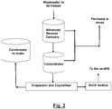
- the ZLD treatment process according to the invention comprises the abovementioned three stages associated, respectively, to desalination, concentration and evaporation-crystallization, placed in series and where the concentrate of each stage is introduced in the following stage.
- the ZLD treatment process according to the invention has greater economic viability than those zero discharge processes because of including an intermediate concentration stage (second stage) to further reduce the volume of the desalination stage (the first stage of advanced reverse osmosis) prior to the evaporation and crystallization stage (third stage).
- the zero liquid discharge treatment process object of the present invention which has been schematically depicted in Fig. 1 comprises mainly three steps: 1) a first step of desalination by advanced reverse osmosis; 2) a second step of concentration by applying one of the technologies of the group formed by vibratory osmosis, forward osmosis and humidification-dehumidification; and 3) a third step of evaporation-crystallization.
- Fig. 2 a general scheme of a system to perform the zero liquid discharge treatment process of the invention.
- CCD-RO Closed-Circuit Desalination Reverse-Osmosis technology
- a ReFlex RO system is a reverse osmosis system comprised of off-the-shelf equipment including membranes which features Desalitech's advanced and proprietary process design and engineering.
- Desalitech's ReFlex products work by recirculating pressurized feedwater until a desired recovery level is reached. Brine is replaced with fresh feed without stopping the flow of pressurized feed or permeate.
- the low initial pressure of each CCDTM sequence means a lower average operating pressure and less pump energy than required in traditional RO systems.
- ReFlex RO systems achieve recovery by recirculation, not with multiple membrane elements and stages in series, and can therefore reach any desired recovery percentage in a single stage. Over 97% has been demonstrated, limited only by the scaling characteristics of the pretreated feed water. Recovery is adjustable at the system control panel, providing unmatched flexibility. Cross flow supplied by a circulation pump washes the membrane and salinity cycling disrupts and greatly reduces scaling and fouling.
- Cycle times are shorter than the induction time for scale deposition and frequent and complete brine rejection can stop and even reverse precipitation, making very high recovery rates possible even from difficult source waters.
- Short membrane arrays and high cross flow also allow ReFlex systems to operate at higher average flux rates without exceeding membrane manufacturer's flow or recovery specifications. Over five years of continuous operation in commercial installations has proven that ReFlex products are reliable.
- RO Reverse Osmosis
- FR Flow Reversal
- This is a two or three stage osmosis system with continuous operation but alternating the different stages periodically with each other: from time to time the last stage in which the concentration of salts and therefore the precipitation potential are greater, are gone interchanging with the first stage by means of a system of valves that treat the liquid effluent of lower concentration. In this way it is also avoided giving time to the formation of precipitates and the degree of recovery is increased.
- This process for scale prevention on membranes surfaces works by periodically switching the flow direction in RO pressure vessel arrays.
- the frequency of switching is dictated by the time it takes for a supersaturated solution in the concentrate to grow a population of scale particles that can allow continued scale growth (denoted the "Induction Time”).
- Induction Time By using the effectively under- saturated feed to sweep away the beginning scale particles in the concentrate before they exceed a critical size, extensive precipitation is prevented. As a consequence, the system can reach higher recoveries.
- the flow reversal principle is based on the fact that during filtration, the feed flow and the brine flow are switched before supersaturated solutions can precipitate from the concentrate onto the membrane.
- Vibratory Osmosis stage of osmosis that incorporates vibratory membranes that achieve recovering water and concentrating the rejection of the previous stage with high content in solids and high potential of formation of precipitates.
- VSEP Vibratory Shear Enhanced Processing
- New Logic Research, Inc. which are made of various polymers such as polyethersulfone, polyamides, and other thin film composites.
- VSEP Vibratory Shear Enhanced Processing
- Over 200 different membranes types are routinely employed in VSEP systems. Vibration is applied to the membranes to avoid precipitation of scaling agents. By doing so, it is possible to increase the recovery efficiency.
- VSEP uses the same thin film polymeric membranes found in spiral-would RO membrane systems, but they are developed in a different way. The membranes are attached to evenly spaced discs than tightly wound around a spacer.
- VSEP By performing a shift approximately 54 times per second, VSEP can achieve up to 90% recovery in a single pass. By arranging VSEP systems in series, recoveries greater than 99% are attainable. VSEP helps meet discharge guidelines, recycles water and improves mine economics.
- a VSEP system occupying only 20 square feet of floor space can support up to 1500 square feet of membrane area and do the work of a system 10 to 100 times larger.
- the system is also modular for easy expansion and its installation is no more complicated than the installation of a pump.
- Forward osmosis stage that uses forward osmosis (FO) membranes to concentrate the rejection with a solids content and moderate precipitate formation potential.
- F forward osmosis
- the water passes from the rejection of the previous stage to a solution of higher salinity due to the difference in osmotic pressure.
- the PFO Recycler is a combined FO and RO process using off-the shelf RO products configured in an easy to operate design specifically designed to maximize efficiency of Porifera's patented FO elements and systems.
- the PFO Concentrator is a modified FO and RO process that utilizes certain aspects of combining FO and multiple RO steps to achieve higher salinity concentrations using less energy than thermal processes.
- Membrane and elements by Porifera Inc. provide optimal flux and rejection in the market. The combination of best membrane and best element provides the smallest footprint, lowest CAPEX, and lowest OPEX FO based system.
- the plate and frame (PF) format has the advantage of a short path on the permeate/draw solution side of the membrane, which improves hydrodynamic efficiency and has the potential to reduce concentration polarization.
- the plate separation is quite wide to ensure that the feed channels do not become clogged.
- FO a narrower feed channel is used, and this gives a good packing density.
- the channel width has to be carefully selected to ensure that there is not an excessive pressure drop at the cross-flow velocity employed for the channel length required.
- Porifera Inc. uses a building block system made up by several PFO modules and the PFO modules are made by several PFO elements piled up.
- the element sizes used are relatively small with a typical commercial product having a 7 m 2 membrane area. Different spacer options are used depending on application.
- the products are claimed to be able to operate in the key competitive flux range of around 30 Imh or more at a low-pressure loss across the module.
- the PFO module has an important flexibility and versatility of the feed and draw flow arrangement, with the possibility of configuring the elements in the stack for series, parallel, and tapered flow schemes. In series, cross-flow velocity can be increased whereas if there is a significant concentration change in a single pass, the flow can be configured in parallel.
- a FO based process provides many benefits when treating challenging waste streams. These benefits include high fouling resistance to most particulates, organics, and other constituents that often lead to rapid fouling and downtime for other membrane technologies (e.g., MF, UF, NF, and RO) and thermal technologies.
- membrane technologies e.g., MF, UF, NF, and RO
- Oasys Water, Inc. has developed the ClearFlo family of products and claim it can be applied to treat industrial wastewaters containing up to 5 times the salinity of seawater.
- the ClearFlo family of Water Transformation Solutions includes three key components: its patented forward osmosis membranes, a unique draw solution together with a draw solution recovery system.
- the ClearFlo Membrane Brine Concentrator (MBC)TM incorporates the FO membrane elements, the patented draw solution as well as the recovery system.
- Oasys Water, Inc. has developed a forward osmosis system that uses a specially formulated draw solution that forces fresh water across the membrane. Feed water enters the system at one side of the membrane module as draw solution flows in from the other end in opposite direction. The concentration gradient formed drives the water across the semi permeable membrane diluting the draw solution.
- the dilute draw solution is regenerated using a thermal recovery process. In the thermal recovery system, the diluted draw solution is recovered by heating the solution to evaporate the draw solutes, leaving behind purified water.
- the MBCTM system based on Engineered Osmosis (ie Forward Osmosis), can reduce disposal volumes by more than 80%, which in turn reduces the total cost of water treatment by up to 30%. It can also treat high saline waters with salt content ranging from 5 to 15% and generates a drinking water quality reuse product together with a reduced volume brine for disposal It can achieve up to 85% water recovery and discharges brine with up to 25% salt concentration.
- Engineered Osmosis ie Forward Osmosis
- the technology can use renewable energy sources such as solarthermal, geothermal and industrial cogeneration heat.
- the ClearFlo Complete zero liquid discharge (ZLD) system can operate with a lower capacity crystallizer, requiring less thermal and electrical energy inputs and lower total cost.
- Oasys Water Inc. offers the ClearFlo Complete system as a comprehensive solution in partnership with the leading crystallizer providers and a network of leading EPCs and system operators.
- the ClearFlo Complete system provides a path to ZLD with lower cost, more reliable operation, and a greater operating flexibility when comparing to other technologies.
- the pretreated feed is pumped to the MBCTM System Feed Tank. From the system feed tank, sodium bisulfite and anti-scalant are dosed inline to deoxidize and control scale, respectively, as the stream is pumped to the FO Membrane Array.
- Feed water and concentrated draw solution flow countercurrent through the FO modules separated by the high performance Oasys FO membrane. Water diffuses across the membrane, diluting the draw solution while simultaneously concentrating greater than 99 percent of the feed water dissolved solids in the concentrated brine.
- Diluted draw solution exits the FO Array and is pumped into the Draw Recovery Column where the draw solutes are stripped from the solution along with some water vapour.
- the concentrated brine exiting the FO membrane array is pumped into the Brine Column where any draw solutes that reverse-permeated into the brine are also recovered and then routed to the Draw Recovery Column.
- the mixed gas stream flows out the top of the Draw Recovery Column, where it is compressed and fully condensed in a heat exchanger.
- the Draw Recovery and Brine Column reboilers both utilize customer-supplied steam as an energy source.
- the condenser heat exchanger utilizes customer-supplied cooling water as a heat sink.
- Intermediate product water is collected at the bottom of the Draw Recovery Column and passed through the Polishing RO System. This step reduces the product water TDS to below 500 mg/L and ensures recovery of the remaining nonvolatized draw solutes.
- the concentrate from the RO system is routed to the MBC System Feed Tank.
- the high quality, low TDS permeate from the RO system can be reused in the site's operations or safely discharged.
- the MBC draw solution recovery system integrates the Draw Recovery Column, the Brine Column, and the Polishing RO in order to maintain virtually 100% of the draw solutes within the system while maximizing energy efficiency.
- Humidification - dehumidification stage in which hot air comes into contact with the rejection of the previous stage. During this contact, the rejection is concentrated when water passes from it to the hot air. In the stage of dehumidification the hot air is cooled condensing the decontaminated water. Concentration through humidification-dehumidification is a variant to be used in cases where there is the possibility of using sources of residual heat from another process or heat from renewable energies.
- the company Gradiant Corporation offers a smart way to implement the humidification-dehumidification stages, by combining the Carrier Gas Extraction (CGETM) technology with the Selective Chemical Extraction (SCETM) process in a continuous, atmospheric pressure, ambient temperature humidification-dehumidification (HDH) desalination process to vaporize water controlling co-precipitation effects.
- Air is recirculated through a humidifier and multistage bubble column dehumidifier in a closed loop.
- As saline feedwater enters the unit it is preheated in the dehumidifier before being heated an additional 10-15°C using a natural gas-fired boiler. Some of the feedwater is evaporated as it is sprayed over a packed bed.
- the water-saturated air is then pumped up through small holes in a series of shallow, water-filled trays in the dehumidifier. As water bubbles pass through the fresh water in the trays, it joins the water it is passing through creating more fresh water. Meanwhile the nonevaporated portion of the feed is removed as saturated brine. This so-called “bubble column” allows condensation of water vapor without needing expensive metal heat exchangers.
- Selective Chemical Extraction is a proprietary set of treatment technologies that are cost-effective improvements on conventional precipitation technologies. They were designed to address treatment challenges posed by high levels of contamination found in produces and flowback waters.
- Selective Chemical Extraction is a multi-step treatment process customizable to meet any effluent quality including oil and grease removal, H2S stripping, VOC and semi-volatile removal, ion-specific removal and lamella clarification.
- SCE Selective Chemical Extraction
- SCETM Selective Chemical Extraction
- Additional pretreatment may include oil and grease removal, H2S stripping, VOC and semi-volatile removal, ion specific removal and lamella clarification.
- SCETM is operated in the oilfield today by Gradiant Corporation producing various grades of clean brine at low costs and with minimal operator interference.
- CGETM Carrier Gas Extraction
- Carrier gas extraction (CGE) process recirculates air through a humidifier and multistage bubble column dehumidifier in a closed loop.
- CGE Carrier gas extraction
- saline feedwater enters the unit it is preheated in the dehumidifier before being heated an additional 10-15°C using a natural gas-fired boiler.
- Some of the feedwater is evaporated as it is sprayed over a packed bed and condensed as distillate in the dehumidifier. Meanwhile, the nonevaporated portion of the feed is removed as saturated brine and the now re-humidified air is then returned to the dehumidifier column to continue the process.
- the CGE desalination technology can achieve high recoveries stated to be in the 70-85% range for saline feedwater and is stated to be a cost-effective version of standard chemical-precipitation techniques.
- the combination of technologies, according to Gradiant allows these systems to treat waters with higher levels of contaminants.
- Custom Control systems are used to optimize the system to run at peak thermal performance, minimize operator intervention, and minimize chemical consumption.
- several design innovations allow these systems to use less energy and treat water at lower costs than competing treatment methods.
- Design innovations include vaporizing the water below boiling temperatures using the dry air carrier gas, incorporating a column with microbubbles providing a direct-contact condenser that optimizes condensing surfaces resulting in more efficient heat transfer and minimizes hardware, utilizing lower temperature differences between the warm and cool water than in a conventional dehumidifying system, and using inexpensive materials in the heat exchanger.
- the technologies can produce water of specific characteristics ranging from 50 ppm TDS (total dissolved solids) to 260,000 ppm TDS.
- the zero liquid discharge stage acts as a crystallizer, recovering the reject water from the concentration stage by evaporation and producing a stream of solids.
- This part of the system comprises evaporators followed by crystallizers.
- the evaporators the volume of the liquid effluent is reduced by evaporation, obtaining a condensate of water.
- the crystallizers the contaminants present in the liquid effluent precipitate with the solids. Examples of evaporators which may be used are the ones offered by the companies GE Power & Water, Evatherm and Inerco.
Landscapes
- Life Sciences & Earth Sciences (AREA)
- Hydrology & Water Resources (AREA)
- Engineering & Computer Science (AREA)
- Environmental & Geological Engineering (AREA)
- Water Supply & Treatment (AREA)
- Chemical & Material Sciences (AREA)
- Organic Chemistry (AREA)
- Separation Using Semi-Permeable Membranes (AREA)
Priority Applications (2)
| Application Number | Priority Date | Filing Date | Title |
|---|---|---|---|
| EP18195919.8A EP3517508A1 (fr) | 2018-09-21 | 2018-09-21 | Procédé de traitement de décharge de liquide zéro pour récupérer de l'eau à partir d'un effluent liquide contaminé en vue de sa réutilisation ultérieure |
| ES201930814A ES2754898R1 (es) | 2018-09-21 | 2019-09-20 | Proceso de tratamiento de descarga cero de líquidos para recuperar agua de un efluente líquido contaminado para su posterior reutilización |
Applications Claiming Priority (1)
| Application Number | Priority Date | Filing Date | Title |
|---|---|---|---|
| EP18195919.8A EP3517508A1 (fr) | 2018-09-21 | 2018-09-21 | Procédé de traitement de décharge de liquide zéro pour récupérer de l'eau à partir d'un effluent liquide contaminé en vue de sa réutilisation ultérieure |
Publications (1)
| Publication Number | Publication Date |
|---|---|
| EP3517508A1 true EP3517508A1 (fr) | 2019-07-31 |
Family
ID=63798777
Family Applications (1)
| Application Number | Title | Priority Date | Filing Date |
|---|---|---|---|
| EP18195919.8A Withdrawn EP3517508A1 (fr) | 2018-09-21 | 2018-09-21 | Procédé de traitement de décharge de liquide zéro pour récupérer de l'eau à partir d'un effluent liquide contaminé en vue de sa réutilisation ultérieure |
Country Status (2)
| Country | Link |
|---|---|
| EP (1) | EP3517508A1 (fr) |
| ES (1) | ES2754898R1 (fr) |
Cited By (2)
| Publication number | Priority date | Publication date | Assignee | Title |
|---|---|---|---|---|
| CN110451596A (zh) * | 2019-08-28 | 2019-11-15 | 黑珀(上海)工业技术有限公司 | 一种载气萃取hpe蒸发系统 |
| WO2021069960A1 (fr) * | 2019-10-08 | 2021-04-15 | Saline Water Conversion Corporation | Système et procédé de dessalement et de production de minéraux à récupération élevée |
Citations (5)
| Publication number | Priority date | Publication date | Assignee | Title |
|---|---|---|---|---|
| US20020108906A1 (en) * | 2000-07-07 | 2002-08-15 | Hidayat Husain | Multi-stage filtration and softening module and reduced scaling operation |
| US20140224716A1 (en) * | 2013-02-08 | 2014-08-14 | Oasys Water, Inc. | Osmotic separation systems and methods |
| CN205603386U (zh) * | 2016-01-14 | 2016-09-28 | 麦王环境技术股份有限公司 | 浓盐水零排放膜浓缩设备 |
| US20170216774A1 (en) * | 2016-01-29 | 2017-08-03 | Massachusetts Institute Of Technology | Batch Pressure-Driven Membrane Liquid Separation Using A Pressure Exchanger for Efficiency |
| CN108423910A (zh) * | 2018-05-17 | 2018-08-21 | 北京今大禹环境技术股份有限公司 | 一种利用废热实现高盐高有机物废水零排放的处理系统 |
Family Cites Families (5)
| Publication number | Priority date | Publication date | Assignee | Title |
|---|---|---|---|---|
| IL157430A (en) * | 2003-08-17 | 2009-08-03 | Avi Efraty | Apparatus for continuous closed circuit desalination under variable pressure with a single container |
| ES2375002B1 (es) * | 2008-07-30 | 2013-02-11 | Desalación Integral Systems, S.L. | Perfeccionamientos en el objeto de la patente n. p200600257 por: planta desaladora-depuradora de aguas salobres y residuos industriales con descarga líquida cero. |
| US8727325B2 (en) * | 2011-05-24 | 2014-05-20 | Saltworks Technologies Inc. | Method, apparatus and system for concentrating solutions using evaporation |
| CN207537309U (zh) * | 2017-11-06 | 2018-06-26 | 西安热工研究院有限公司 | Igcc电厂煤气化与含硫混合废水处理回用零排放系统 |
| CN209065675U (zh) * | 2018-09-14 | 2019-07-05 | 山东聊城倍杰特环保工程设计有限公司 | 一种高含盐废水的多级零排放处理设备 |
-
2018
- 2018-09-21 EP EP18195919.8A patent/EP3517508A1/fr not_active Withdrawn
-
2019
- 2019-09-20 ES ES201930814A patent/ES2754898R1/es not_active Withdrawn
Patent Citations (5)
| Publication number | Priority date | Publication date | Assignee | Title |
|---|---|---|---|---|
| US20020108906A1 (en) * | 2000-07-07 | 2002-08-15 | Hidayat Husain | Multi-stage filtration and softening module and reduced scaling operation |
| US20140224716A1 (en) * | 2013-02-08 | 2014-08-14 | Oasys Water, Inc. | Osmotic separation systems and methods |
| CN205603386U (zh) * | 2016-01-14 | 2016-09-28 | 麦王环境技术股份有限公司 | 浓盐水零排放膜浓缩设备 |
| US20170216774A1 (en) * | 2016-01-29 | 2017-08-03 | Massachusetts Institute Of Technology | Batch Pressure-Driven Membrane Liquid Separation Using A Pressure Exchanger for Efficiency |
| CN108423910A (zh) * | 2018-05-17 | 2018-08-21 | 北京今大禹环境技术股份有限公司 | 一种利用废热实现高盐高有机物废水零排放的处理系统 |
Cited By (2)
| Publication number | Priority date | Publication date | Assignee | Title |
|---|---|---|---|---|
| CN110451596A (zh) * | 2019-08-28 | 2019-11-15 | 黑珀(上海)工业技术有限公司 | 一种载气萃取hpe蒸发系统 |
| WO2021069960A1 (fr) * | 2019-10-08 | 2021-04-15 | Saline Water Conversion Corporation | Système et procédé de dessalement et de production de minéraux à récupération élevée |
Also Published As
| Publication number | Publication date |
|---|---|
| ES2754898R1 (es) | 2020-04-27 |
| ES2754898A2 (es) | 2020-04-20 |
Similar Documents
| Publication | Publication Date | Title |
|---|---|---|
| Kim | A review of desalting process techniques and economic analysis of the recovery of salts from retentates | |
| CN108264180B (zh) | 一种高含盐废水的零排放处理方法及系统 | |
| US20140299529A1 (en) | Systems, Apparatus, and Methods for Separating Salts from Water | |
| EP2374761A2 (fr) | Système de traitement des eaux à zéro décharge liquide et procédé | |
| Wenten et al. | Integrated processes for desalination and salt production: A mini-review | |
| US9822021B2 (en) | Forward osmosis separation processes | |
| CN108218087B (zh) | 一种基于多级电驱动离子膜处理高含盐废水的系统 | |
| CN108275820A (zh) | 水处理方法 | |
| CN108275815B (zh) | 一种高盐废水零排放蒸发结晶盐分质系统及方法 | |
| KR102169490B1 (ko) | 고농도 폐수의 다단계 진공 증발 농축을 이용한 무방류 폐수 처리시스템 | |
| US20130233797A1 (en) | Methods for osmotic concentration of hyper saline streams | |
| US10384967B2 (en) | Water treatment systems and methods | |
| WO2013188450A1 (fr) | Procédés de concentration par distillation membranaire durable de courants hyper salins | |
| US20220017385A1 (en) | Temperature swing solvent extraction for descaling of feedstreams | |
| US20250091906A1 (en) | Temperature swing solvent extraction for descaling of feedstreams | |
| US20160052812A1 (en) | Reject recovery reverse osmosis (r2ro) | |
| CN108623062A (zh) | 一种多级膜结晶综合处理含盐废水的系统 | |
| EA022491B1 (ru) | Система и способ термической дистилляции | |
| CN205603386U (zh) | 浓盐水零排放膜浓缩设备 | |
| EP3242858B1 (fr) | Procédé et système de purification d'eau osmotique fonctionnant à l'énergie solaire | |
| Prabakar et al. | Emerging investigator series: a state-of-the-art review on large-scale desalination technologies and their brine management | |
| CN206901951U (zh) | 垃圾焚烧飞灰废水零排放和资源化装置 | |
| ES2754898A2 (es) | Proceso de tratamiento de descarga cero de líquidos para recuperar agua de un efluente líquido contaminado para su posterior reutilización | |
| Bordbar et al. | A review on sustainable hybrid water treatment processes | |
| CN105293803A (zh) | 一种高浓度废水的处理方法 |
Legal Events
| Date | Code | Title | Description |
|---|---|---|---|
| PUAI | Public reference made under article 153(3) epc to a published international application that has entered the european phase |
Free format text: ORIGINAL CODE: 0009012 |
|
| STAA | Information on the status of an ep patent application or granted ep patent |
Free format text: STATUS: THE APPLICATION HAS BEEN PUBLISHED |
|
| AK | Designated contracting states |
Kind code of ref document: A1 Designated state(s): AL AT BE BG CH CY CZ DE DK EE ES FI FR GB GR HR HU IE IS IT LI LT LU LV MC MK MT NL NO PL PT RO RS SE SI SK SM TR |
|
| AX | Request for extension of the european patent |
Extension state: BA ME |
|
| STAA | Information on the status of an ep patent application or granted ep patent |
Free format text: STATUS: THE APPLICATION IS DEEMED TO BE WITHDRAWN |
|
| 18D | Application deemed to be withdrawn |
Effective date: 20200201 |