EP3517685A1 - Pièce rapportée pour une machine de nettoyage du sol - Google Patents
Pièce rapportée pour une machine de nettoyage du sol Download PDFInfo
- Publication number
- EP3517685A1 EP3517685A1 EP18153709.3A EP18153709A EP3517685A1 EP 3517685 A1 EP3517685 A1 EP 3517685A1 EP 18153709 A EP18153709 A EP 18153709A EP 3517685 A1 EP3517685 A1 EP 3517685A1
- Authority
- EP
- European Patent Office
- Prior art keywords
- attachment
- cleaning machine
- coupling
- floor cleaning
- actuating shaft
- Prior art date
- Legal status (The legal status is an assumption and is not a legal conclusion. Google has not performed a legal analysis and makes no representation as to the accuracy of the status listed.)
- Granted
Links
Images

Classifications
-
- A—HUMAN NECESSITIES
- A47—FURNITURE; DOMESTIC ARTICLES OR APPLIANCES; COFFEE MILLS; SPICE MILLS; SUCTION CLEANERS IN GENERAL
- A47L—DOMESTIC WASHING OR CLEANING; SUCTION CLEANERS IN GENERAL
- A47L11/00—Machines for cleaning floors, carpets, furniture, walls, or wall coverings
- A47L11/24—Floor-sweeping machines, motor-driven
-
- A—HUMAN NECESSITIES
- A47—FURNITURE; DOMESTIC ARTICLES OR APPLIANCES; COFFEE MILLS; SPICE MILLS; SUCTION CLEANERS IN GENERAL
- A47L—DOMESTIC WASHING OR CLEANING; SUCTION CLEANERS IN GENERAL
- A47L11/00—Machines for cleaning floors, carpets, furniture, walls, or wall coverings
- A47L11/28—Floor-scrubbing machines, motor-driven
-
- A—HUMAN NECESSITIES
- A47—FURNITURE; DOMESTIC ARTICLES OR APPLIANCES; COFFEE MILLS; SPICE MILLS; SUCTION CLEANERS IN GENERAL
- A47L—DOMESTIC WASHING OR CLEANING; SUCTION CLEANERS IN GENERAL
- A47L11/00—Machines for cleaning floors, carpets, furniture, walls, or wall coverings
- A47L11/28—Floor-scrubbing machines, motor-driven
- A47L11/282—Floor-scrubbing machines, motor-driven having rotary tools
- A47L11/283—Floor-scrubbing machines, motor-driven having rotary tools the tools being disc brushes
-
- A—HUMAN NECESSITIES
- A47—FURNITURE; DOMESTIC ARTICLES OR APPLIANCES; COFFEE MILLS; SPICE MILLS; SUCTION CLEANERS IN GENERAL
- A47L—DOMESTIC WASHING OR CLEANING; SUCTION CLEANERS IN GENERAL
- A47L11/00—Machines for cleaning floors, carpets, furniture, walls, or wall coverings
- A47L11/40—Parts or details of machines not provided for in groups A47L11/02 - A47L11/38, or not restricted to one of these groups, e.g. handles, arrangements of switches, skirts, buffers, levers
-
- A—HUMAN NECESSITIES
- A47—FURNITURE; DOMESTIC ARTICLES OR APPLIANCES; COFFEE MILLS; SPICE MILLS; SUCTION CLEANERS IN GENERAL
- A47L—DOMESTIC WASHING OR CLEANING; SUCTION CLEANERS IN GENERAL
- A47L11/00—Machines for cleaning floors, carpets, furniture, walls, or wall coverings
- A47L11/40—Parts or details of machines not provided for in groups A47L11/02 - A47L11/38, or not restricted to one of these groups, e.g. handles, arrangements of switches, skirts, buffers, levers
- A47L11/4036—Parts or details of the surface treating tools
-
- A—HUMAN NECESSITIES
- A47—FURNITURE; DOMESTIC ARTICLES OR APPLIANCES; COFFEE MILLS; SPICE MILLS; SUCTION CLEANERS IN GENERAL
- A47L—DOMESTIC WASHING OR CLEANING; SUCTION CLEANERS IN GENERAL
- A47L11/00—Machines for cleaning floors, carpets, furniture, walls, or wall coverings
- A47L11/40—Parts or details of machines not provided for in groups A47L11/02 - A47L11/38, or not restricted to one of these groups, e.g. handles, arrangements of switches, skirts, buffers, levers
- A47L11/4052—Movement of the tools or the like perpendicular to the cleaning surface
- A47L11/4055—Movement of the tools or the like perpendicular to the cleaning surface for lifting the tools to a non-working position
-
- E—FIXED CONSTRUCTIONS
- E01—CONSTRUCTION OF ROADS, RAILWAYS, OR BRIDGES
- E01H—STREET CLEANING; CLEANING OF PERMANENT WAYS; CLEANING BEACHES; DISPERSING OR PREVENTING FOG IN GENERAL CLEANING STREET OR RAILWAY FURNITURE OR TUNNEL WALLS
- E01H1/00—Removing undesirable matter from roads or like surfaces, with or without moistening of the surface
- E01H1/02—Brushing apparatus, e.g. with auxiliary instruments for mechanically loosening dirt
- E01H1/05—Brushing apparatus, e.g. with auxiliary instruments for mechanically loosening dirt with driven brushes
- E01H1/053—Brushing apparatus, e.g. with auxiliary instruments for mechanically loosening dirt with driven brushes having vertical axes
-
- E—FIXED CONSTRUCTIONS
- E01—CONSTRUCTION OF ROADS, RAILWAYS, OR BRIDGES
- E01H—STREET CLEANING; CLEANING OF PERMANENT WAYS; CLEANING BEACHES; DISPERSING OR PREVENTING FOG IN GENERAL CLEANING STREET OR RAILWAY FURNITURE OR TUNNEL WALLS
- E01H1/00—Removing undesirable matter from roads or like surfaces, with or without moistening of the surface
- E01H1/02—Brushing apparatus, e.g. with auxiliary instruments for mechanically loosening dirt
- E01H1/05—Brushing apparatus, e.g. with auxiliary instruments for mechanically loosening dirt with driven brushes
- E01H1/056—Brushing apparatus, e.g. with auxiliary instruments for mechanically loosening dirt with driven brushes having horizontal axes
-
- A—HUMAN NECESSITIES
- A01—AGRICULTURE; FORESTRY; ANIMAL HUSBANDRY; HUNTING; TRAPPING; FISHING
- A01D—HARVESTING; MOWING
- A01D42/00—Mowers convertible to apparatus for purposes other than mowing; Mowers capable of performing operations other than mowing
- A01D42/06—Sweeping or cleaning lawns or other surfaces
Definitions
- the present invention relates to an attachment for attachment to a floor cleaning machine.
- Attachments for floor cleaning machines which can be attached to the machine frame, for example, at the front end or the rear end, are well known in the prior art. For example, sweeping units, scrubbing units or simply receiving platforms for other devices that can be used to clean a floor surface, such as vacuum cleaners or the like, are supported on the machine frame.
- attachments often have to be disassembled during the cleaning operation of the floor cleaning machine to make it more maneuverable for use in confined spaces.
- attachments require that they be moved between a lowered operating position in which, for example, bristles on the attachment engage with a floor surface to be cleaned and a raised position in which the bristles are out of engagement with the floor surface To be able to move the machine faster and without wear on the bristles. Therefore, in addition to a simple coupling mechanism for the attachment often required that in addition a lifting mechanism is provided, with which the vertical position of the attachment can be changed.
- an attachment and a system of a floor cleaning machine and an attachment to provide that are simple and allow to couple the attachment to the machine frame of the floor cleaning machine and to adjust vertically relative to this.
- the attachment has a base frame comprising a front end and a coupling end, wherein the coupling end in the mounted state on a Floor cleaning machine points to this, while the coupling end points away.
- a support member is provided on the base frame, which is configured to support the attachment relative to a bottom surface and spaced thereof to keep.
- the support element is to be designed to hold the attachment at a height relative to the bottom surface, which allows a floor cleaning machine to be moved up to the attachment such that by a simple vertical movement a first coupling element on the attachment engages a second one Coupling element can be brought to the machine frame of the floor cleaning machine.
- the attachment according to the invention has a first coupling element, which can be brought by a simple vertical movement into engagement with a second coupling element on the floor cleaning machine.
- This first coupling element may, for example, be designed as a hook element which can be brought into engagement with a corresponding eyelet or ring element on the machine frame. But there are also other embodiments conceivable.
- the attachment has a pressure element which is pivotally mounted on the base frame and which can come into abutment with a free end, which is arranged away from the pivot axis of the pressure element with a contact surface on the machine frame of the floor cleaning surface ,
- the contact surface is preferably vertical, but may also be oriented differently.
- an actuating element is provided on the attachment according to the invention, which can be pivoted about a horizontally extending axis in the normal operating state of the attachment relative to the base frame, wherein the actuating element is coupled to an actuating shaft which is supported about a horizontal pivot axis pivotally mounted on the base frame.
- the first coupling element is arranged such that it defines, together with the horizontal pivot axis of the actuating shaft, a transverse plane which runs such that on the one hand the pivot axis extends therein and on the other hand the first coupling element is likewise arranged therein.
- the transverse plane extends transversely to the direction of travel of the floor cleaning machine and from the floor surface upwards through the first coupling element.
- the transverse plane can run in such a way that when the attachment is arranged on a bottom surface in normal operation, the transverse plane is perpendicular to the bottom surface and through the first coupling element.
- the support element is coupled to the actuating shaft, so that during pivoting the actuating shaft, the support element between an extended and at least one retracted position is pivoted, wherein the free end of the support member in the extended position has a greater distance from the base frame than in the at least one retracted position is the case.
- the pressure element is also coupled to the actuating shaft so that it is pivoted when pivoting the actuating shaft between a release position, a coupling position and a Aushebewolf, the position of the free end of the pressure element in the release position along an adjustment direction which is perpendicular to the transverse plane the front end of the base frame is closer than the position of the free end in the Aushebewolf.
- the free end of the pressure element in the release position relative to the coupling end retreated further into the interior of the base frame, as is the case in the Aushebewolf.
- the position of the free end of the pressure element in the coupling position between the position in the release position and in the Aushebewolf is arranged.
- the support element and the pressure element are coupled to the actuating shaft in such a way that when the support element is in the extended position, the pressure element is in the release position.
- the support member is in at least one of the retracted positions when the pressure element is in the raised position or the coupling position.
- the coupling as described above, it is achieved that, when the actuating element, for example in the form of an actuating lever, is actuated such that the support element is moved from the extended to the retracted position, with a vertical movement the attachment is connected relative to the floor cleaning machine, first the first coupling element comes into engagement with the second coupling element on the machine frame of the floor cleaning machine.
- the actuating element or the actuating shaft is first achieved that the attachment is locked to the machine frame.
- the pressure element is moved along the displacement direction to the contact surface, which is provided on the machine frame of the floor cleaning machine and is vertically aligned.
- the pressure element is supported on the machine frame and is in a predetermined angular position, by the position of the free end of the pressure element is fixed, held relative to the machine frame without the attachment must be further supported by the support member on the bottom surface.
- the attachment from the coupling position can be further raised by the fact that the actuating element is moved so that the pressure element moves into the Aushebegna.
- the actuating shaft extends along the pivot axis. However, it is not absolutely necessary for the actuating shaft, to which the pressure element and the support element are coupled, to coincide with the pivot axis thereof.
- the support element is attached directly to the actuating shaft and thus pivots about the pivot axis.
- the support element is attached directly to the actuating shaft and thus pivots about the pivot axis.
- no complicated structures are required to couple the support element with the actuating shaft, so that a pivoting of the actuating shaft then causes a pivotal movement of the support element.
- both the pressure element and the actuating element or only one of them can be fastened directly to the actuating shaft.
- a particularly simple structure is realized in each case.
- an impeller may be provided at the free end of the support member, which allows the attachment to slide over a bottom surface when the support member is in the extended position.
- a guide for the actuating lever which forms the actuating element, is provided which is designed such that the actuating lever, when he out of the is pivoted to the coupling position corresponding position in the release position, a movement parallel to the pivot axis and then performs a pivoting movement about the pivot axis.
- the attachment can be designed as Kehraggregrat, wherein it has a brush element with a central body, on which are provided wegertiernde bristles.
- the brush member is rotationally driven, and the attachment is configured such that the free ends of the bristles are spaced from a bottom surface to be cleaned when the attachment is in the raised position while engaging the bottom surface when in the coupling position located.
- the axis of rotation of the brush element can be either perpendicular or parallel to the pivot axis.
- a system comprising a floor cleaning machine and an attachment according to one of the embodiments described above, wherein a landing gear for moving the floor cleaning machine over a floor surface to be cleaned is provided on the floor cleaning machine or on its machine frame, and the machine frame continues vertically extending abutment surface and seen in the vertical direction overlying second coupling element, which is adapted to be able to engage with the first coupling element on the attachment when the attachment is lowered vertically when the support member is transferred from the extended to the retracted position.
- an attachment 1 described below for a floor cleaning machine 3 which is only indicated schematically, is designed as sweeping unit.
- the floor cleaning machine 3 in this case has a chassis for moving the floor cleaning machine 3 over a floor surface.
- the present invention is not limited to attachments designed as sweeping units, but can also be found in scrubbing units, mowing units or simple receiving platforms for other devices that can be used to clean a floor surface, such as vacuum cleaners or the like.
- an attachment 1 designed as a brush roller brush element 5 with a central body 7 and extending away therefrom bristles 9, wherein in a coupling position, the free ends of Intervene bristles 9 with the bottom surface 11, over which the attachment 1 is moved during operation of the floor cleaning machine 3 by de chassis.
- the attachment 1 In a Aushebe too the attachment 1, the free ends of the bristles 9 are spaced from the bottom surface 11.
- the attachment 1 has two side brushes 13, which also have a central body and extending therefrom bristles 15, wherein also here the bristles 15 are then in engagement with the bottom surface 11 when the attachment 1 is in the coupling position, and of the Floor surface 11 are spaced when the attachment 1 is in the Aushebewolf.
- the sweeping roller 5 rotates about a horizontally extending axis of rotation, while the side brush 13 is driven to rotate about a vertically extending axis of rotation.
- Both the sweeping roller 5 and the side brushes 13 are mounted on a base frame 17 of the attachment 1, to which an actuating shaft 19 is also provided, which extends in the normal operating position of the attachment 1 substantially horizontally and transversely to the direction of movement of the floor cleaning machine 3.
- the actuating shaft 19 is pivotally mounted about a pivot axis on the base frame 17, wherein the pivot axis extends in the embodiment described here along the actuating shaft 19. But it is also conceivable that the actuating shaft pivots about a pivot axis which extends parallel offset to the actuating shaft.
- actuating lever 21 actuating element Fixedly coupled to the actuating shaft 19 is designed as an actuating lever 21 actuating element, which thus also pivots about the pivot axis. Furthermore, a support element 23 is firmly attached to the actuating shaft, so that this at Swiveling the actuating shaft 19 is pivoted with. At the free end of the support member 23, an impeller 25 is mounted in the embodiment described here. The support member 23 with the impeller 25 is adapted to support the attachment 1 in a disassembled state in which it is detached from the floor cleaning machine 3, with a free end on the bottom surface 11,
- a first coupling element 27 is provided on the base frame 17 of the attachment 1, which can engage with a second, attached to the floor cleaning machine 3 coupling element 29.
- the first and the second coupling element 27, 29 are designed such that they can intervene with a vertical movement of the attachment 1 towards the bottom surface 11 relative to the floor cleaning machine 3 with each other so that the attachment 1 against further vertical movement towards the Bottom surface 11 and also a movement parallel to the bottom surface 11 is locked relative to the floor cleaning machine 3.
- the first coupling element 27 is configured as a hook, which engages in the second coupling element 29 designed as an eyelet on the floor cleaning machine 3.
- other configurations are also conceivable here, but in which case it must be ensured that the previously described locking function is realized both in the vertical and in the horizontal direction.
- a pressure element 31 (see Fig. 2 ) fixed so that it is pivoted with a pivoting movement of the actuating shaft 19 with.
- the pressure element 31 is designed and attached to the base frame 17 in such a way that it can come to rest with its free end with a preferably vertically extending contact surface 33 on the floor cleaning machine 3.
- a guide 35 is provided for the actuating lever 21 to the attachment 1, along which the actuating lever 21 is guided.
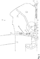
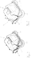
- the actuating lever 21 occupy a position corresponding to a release position, as shown in FIG Fig. 4 is shown and in which the actuating lever 21 is pivoted furthest away from the floor cleaning machine 3 forward (see also Fig. 1 ).
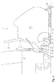
- the actuating lever 21 by pivoting together with the actuating shaft 19 which in Fig. 5 occupy shown position corresponding to a coupling position and also in Fig. 5 is shown.
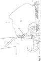
- the guide 35 is designed such that the actuating lever 21, when he from the position corresponding to the coupling position ( Fig. 2 and 5 ) into the release position ( Fig. 1 and 4 ) is pivoted, a movement parallel to the pivot axis or actuating shaft 19 and then performs a pivoting movement about the pivot axis. This ensures that the actuating lever 21 is not in a train from the Aushebewolf Fig. 3 and 6 into the release position ( Fig. 1 and 4 ) can be pivoted.
- the first coupling element 27 and the pivot axis coinciding here with the actuating shaft 19 define a transverse plane V in which the pivot axis or actuating shaft 19 extends.
- the transverse plane V extends transversely to the direction of travel F of the floor cleaning machine 3 and from the bottom surface 11 upwards through the first coupling element 27. In the embodiment described here, the transverse plane V extends in almost vertical direction through the first coupling element 27th
- the support member 23 is so firmly coupled to the actuating shaft 19 that upon pivoting of the actuating shaft 19 by means of the actuating lever 21, the support element between an extended position, the in Fig. 1 is pivoted, and a first retracted position and a second retracted position is pivoted in the Fig. 2 and 3 are reproduced.
- the free end of the support member 23 and thus the impeller 25 has a greater distance from the base frame 17 than in the retracted positions.
- the attachment 1 can be supported in the extended position of the support member 23 of this on the bottom surface 11.
- the pressure element 31 is also fixedly coupled to the actuating shaft 19, in such a way that by pivoting the actuating shaft 19 by means of the actuating lever 21, the pressure element 23 between a release position ( Fig. 1 ), a coupling position ( Fig. 2 ) and a withdrawal order ( Fig. 3 ) is pivoted.
- the connection to the actuating shaft 19 is such that the position of the free end of the pressure element 31 in the release position ( Fig. 1 ), seen along an adjustment direction which is perpendicular to the transverse plane V, the front end of the attachment 1 is closer than in the Aushebegna ( Fig. 3 ) the case is.
- the support element 23 and the pressure element 31 are attached to the actuating shaft 19 so that when the pressure element 31 is pivoted into the release position, the support member 23 is pivoted to the extended position and thus the attachment 1 is supported on the bottom surface 11.
- the pressure member 31 is pivoted by means of the actuating lever 21 in the Aushebewolf or the coupling position, the support member 23 is in one of the two retracted positions, and the attachment 1 is not with the impeller 25 on the bottom surface 11.
- the attachment 1 described above can now be attached in the following manner to a floor cleaning machine 3 and lowered and dug.
- the actuating lever 21 When pivoting the actuating shaft 19 in the release position, the support member 23 is lowered onto the bottom surface 11 and the attachment 1 is raised, so that the first coupling element 27 is disengaged from the second coupling element 29. The attachment 1 is then released from the floor cleaning machine 1.
Landscapes
- Engineering & Computer Science (AREA)
- Architecture (AREA)
- Civil Engineering (AREA)
- Structural Engineering (AREA)
- Nozzles For Electric Vacuum Cleaners (AREA)
- Cleaning In General (AREA)
- Handcart (AREA)
Priority Applications (4)
| Application Number | Priority Date | Filing Date | Title |
|---|---|---|---|
| EP18153709.3A EP3517685B1 (fr) | 2018-01-26 | 2018-01-26 | Pièce rapportée pour une machine de nettoyage du sol |
| KR1020190009308A KR102746428B1 (ko) | 2018-01-26 | 2019-01-24 | 바닥 청소기용 부착 장치 |
| CN201910073842.2A CN110074728B (zh) | 2018-01-26 | 2019-01-25 | 用于洁地机的附件 |
| JP2019011340A JP7197380B2 (ja) | 2018-01-26 | 2019-01-25 | 床清掃機用のアタッチメント |
Applications Claiming Priority (1)
| Application Number | Priority Date | Filing Date | Title |
|---|---|---|---|
| EP18153709.3A EP3517685B1 (fr) | 2018-01-26 | 2018-01-26 | Pièce rapportée pour une machine de nettoyage du sol |
Publications (2)
| Publication Number | Publication Date |
|---|---|
| EP3517685A1 true EP3517685A1 (fr) | 2019-07-31 |
| EP3517685B1 EP3517685B1 (fr) | 2020-07-29 |
Family
ID=61054258
Family Applications (1)
| Application Number | Title | Priority Date | Filing Date |
|---|---|---|---|
| EP18153709.3A Active EP3517685B1 (fr) | 2018-01-26 | 2018-01-26 | Pièce rapportée pour une machine de nettoyage du sol |
Country Status (4)
| Country | Link |
|---|---|
| EP (1) | EP3517685B1 (fr) |
| JP (1) | JP7197380B2 (fr) |
| KR (1) | KR102746428B1 (fr) |
| CN (1) | CN110074728B (fr) |
Cited By (1)
| Publication number | Priority date | Publication date | Assignee | Title |
|---|---|---|---|---|
| CN116927059A (zh) * | 2023-07-25 | 2023-10-24 | 中铁四局集团有限公司 | 一种公路施工用标示线移动涂刷装置 |
Citations (2)
| Publication number | Priority date | Publication date | Assignee | Title |
|---|---|---|---|---|
| FR2229374A1 (en) * | 1973-05-14 | 1974-12-13 | Charpenet Louis Joseph | Tractor drawn mechanical sweeping machine - rotary broom can be compensated fof wear, front lifts for transportation |
| EP2733262A2 (fr) * | 2012-11-20 | 2014-05-21 | Franz Schneider GmbH & Co. KG | Appareil de balayage pour un véhicule d'enfant, notamment pour un trotteur |
Family Cites Families (9)
| Publication number | Priority date | Publication date | Assignee | Title |
|---|---|---|---|---|
| JP2602125Y2 (ja) * | 1996-07-12 | 1999-12-27 | 山崎産業株式会社 | 床面等処理装置 |
| JP3804265B2 (ja) * | 1998-03-31 | 2006-08-02 | 株式会社豊田自動織機 | 掃除車の制動装置 |
| JP5243879B2 (ja) * | 2008-08-04 | 2013-07-24 | 富士重工業株式会社 | 清掃ロボットのサイドブラシ支持装置 |
| DE102010038303A1 (de) * | 2010-07-22 | 2012-01-26 | Alfred Kärcher Gmbh & Co. Kg | Saugreinigungsvorrichtung |
| CN103717117A (zh) * | 2011-08-02 | 2014-04-09 | 阿尔弗雷德·凯驰两合公司 | 可行驶的地板清洁机和用于操作地板清洁机的方法 |
| CN104023611B (zh) * | 2011-11-02 | 2016-11-23 | 阿尔弗雷德·凯驰两合公司 | 用手引导的地板清洁机 |
| EP2954817B1 (fr) * | 2014-06-11 | 2016-10-26 | Hako GmbH | Machine de nettoyage du sol |
| WO2016150485A1 (fr) * | 2015-03-24 | 2016-09-29 | Alfred Kärcher Gmbh & Co. Kg | Machine de nettoyage de sol et procédé pour faire fonctionner une machine de nettoyage de sol |
| JP6272543B2 (ja) * | 2017-10-31 | 2018-01-31 | シャープ株式会社 | 掃除機 |
-
2018
- 2018-01-26 EP EP18153709.3A patent/EP3517685B1/fr active Active
-
2019
- 2019-01-24 KR KR1020190009308A patent/KR102746428B1/ko active Active
- 2019-01-25 JP JP2019011340A patent/JP7197380B2/ja active Active
- 2019-01-25 CN CN201910073842.2A patent/CN110074728B/zh active Active
Patent Citations (2)
| Publication number | Priority date | Publication date | Assignee | Title |
|---|---|---|---|---|
| FR2229374A1 (en) * | 1973-05-14 | 1974-12-13 | Charpenet Louis Joseph | Tractor drawn mechanical sweeping machine - rotary broom can be compensated fof wear, front lifts for transportation |
| EP2733262A2 (fr) * | 2012-11-20 | 2014-05-21 | Franz Schneider GmbH & Co. KG | Appareil de balayage pour un véhicule d'enfant, notamment pour un trotteur |
Cited By (1)
| Publication number | Priority date | Publication date | Assignee | Title |
|---|---|---|---|---|
| CN116927059A (zh) * | 2023-07-25 | 2023-10-24 | 中铁四局集团有限公司 | 一种公路施工用标示线移动涂刷装置 |
Also Published As
| Publication number | Publication date |
|---|---|
| EP3517685B1 (fr) | 2020-07-29 |
| KR102746428B1 (ko) | 2024-12-23 |
| CN110074728A (zh) | 2019-08-02 |
| KR20190091210A (ko) | 2019-08-05 |
| CN110074728B (zh) | 2021-09-14 |
| JP7197380B2 (ja) | 2022-12-27 |
| JP2019126738A (ja) | 2019-08-01 |
Similar Documents
| Publication | Publication Date | Title |
|---|---|---|
| DE19654867C2 (de) | Schwenkbare Anhängerkupplung für Kraftfahrzeuge | |
| DE3024664C2 (fr) | ||
| DE60309224T2 (de) | Reifenabdrückvorrichtung und Reifendemontiereinheit für eine Reifenwechselmaschine | |
| EP2954817B1 (fr) | Machine de nettoyage du sol | |
| EP3354829B1 (fr) | Dispositif d'actionnement pour véhicule automobile | |
| DE102016118887B4 (de) | Luftleitvorrichtung für ein Kraftfahrzeug | |
| EP0007335B1 (fr) | Bac a pieds repliables | |
| EP3517685B1 (fr) | Pièce rapportée pour une machine de nettoyage du sol | |
| EP1714603B1 (fr) | Machine à nettoyer les sols | |
| DE2638904C2 (de) | Oberlenker einer Dreipunktanbauvorrichtung zum Anbau von Arbeitsgeräten an einen Ackerschlepper | |
| EP1371305B1 (fr) | Table extensible | |
| DE102013220149B4 (de) | Bodenreinigungsmaschine mit Transportsicherung für Seitenbesen | |
| EP3403562B1 (fr) | Dispositif de ventouse pour une machine de nettoyage de sol et machine de nettoyage de sol | |
| DE20120964U1 (de) | Abstützvorrichtung für Baumaschinen wie Hydraulikbagger u.dgl. | |
| DE102012023357A1 (de) | Vorrichtung und Verfahren zur Positionierung und Arretierung von Ergänzungsteilen für den Kranbetrieb | |
| DE8715674U1 (de) | Heuwerbungsmaschine | |
| DE910028C (de) | Einrichtung zum Kuppeln des Aufliegers von Sattelschleppern | |
| DE2905460A1 (de) | Gewinnungsmaschine | |
| DE4012586C1 (en) | Height-adjustable agricultural trailer coupling - has actuating shaft, protruding coaxially into guide bush, coupled to guide plates | |
| EP0831054A2 (fr) | Dispositif de levage, en particulier plate-forme à ciseaux | |
| DE19752234A1 (de) | Antriebsvorrichtung für hin- und hergehende Schwenkbewegungen | |
| DE2435477B1 (de) | Geräteanbauvorrichtung mit Abstützung der Oberlenker gegenüber den Unterlenkern durch Blattfedern, insbesondere für einen Schlepper | |
| DE102004024173B4 (de) | Beschlagsystem für einen Fahrzeugsitz | |
| DE202018001461U1 (de) | Schwenkbare Randscheibe | |
| DE828775C (de) | Hebevorrichtung fuer das Maehmaschinenschneidwerk |
Legal Events
| Date | Code | Title | Description |
|---|---|---|---|
| PUAI | Public reference made under article 153(3) epc to a published international application that has entered the european phase |
Free format text: ORIGINAL CODE: 0009012 |
|
| STAA | Information on the status of an ep patent application or granted ep patent |
Free format text: STATUS: THE APPLICATION HAS BEEN PUBLISHED |
|
| AK | Designated contracting states |
Kind code of ref document: A1 Designated state(s): AL AT BE BG CH CY CZ DE DK EE ES FI FR GB GR HR HU IE IS IT LI LT LU LV MC MK MT NL NO PL PT RO RS SE SI SK SM TR |
|
| AX | Request for extension of the european patent |
Extension state: BA ME |
|
| STAA | Information on the status of an ep patent application or granted ep patent |
Free format text: STATUS: REQUEST FOR EXAMINATION WAS MADE |
|
| 17P | Request for examination filed |
Effective date: 20191125 |
|
| RBV | Designated contracting states (corrected) |
Designated state(s): AL AT BE BG CH CY CZ DE DK EE ES FI FR GB GR HR HU IE IS IT LI LT LU LV MC MK MT NL NO PL PT RO RS SE SI SK SM TR |
|
| GRAP | Despatch of communication of intention to grant a patent |
Free format text: ORIGINAL CODE: EPIDOSNIGR1 |
|
| STAA | Information on the status of an ep patent application or granted ep patent |
Free format text: STATUS: GRANT OF PATENT IS INTENDED |
|
| INTG | Intention to grant announced |
Effective date: 20200206 |
|
| GRAS | Grant fee paid |
Free format text: ORIGINAL CODE: EPIDOSNIGR3 |
|
| GRAA | (expected) grant |
Free format text: ORIGINAL CODE: 0009210 |
|
| STAA | Information on the status of an ep patent application or granted ep patent |
Free format text: STATUS: THE PATENT HAS BEEN GRANTED |
|
| REG | Reference to a national code |
Ref country code: HK Ref legal event code: DE Ref document number: 40012090 Country of ref document: HK |
|
| AK | Designated contracting states |
Kind code of ref document: B1 Designated state(s): AL AT BE BG CH CY CZ DE DK EE ES FI FR GB GR HR HU IE IS IT LI LT LU LV MC MK MT NL NO PL PT RO RS SE SI SK SM TR |
|
| REG | Reference to a national code |
Ref country code: CH Ref legal event code: EP |
|
| REG | Reference to a national code |
Ref country code: DE Ref legal event code: R096 Ref document number: 502018001970 Country of ref document: DE |
|
| REG | Reference to a national code |
Ref country code: AT Ref legal event code: REF Ref document number: 1295933 Country of ref document: AT Kind code of ref document: T Effective date: 20200815 |
|
| REG | Reference to a national code |
Ref country code: IE Ref legal event code: FG4D Free format text: LANGUAGE OF EP DOCUMENT: GERMAN |
|
| REG | Reference to a national code |
Ref country code: LT Ref legal event code: MG4D |
|
| REG | Reference to a national code |
Ref country code: NL Ref legal event code: MP Effective date: 20200729 |
|
| PG25 | Lapsed in a contracting state [announced via postgrant information from national office to epo] |
Ref country code: FI Free format text: LAPSE BECAUSE OF FAILURE TO SUBMIT A TRANSLATION OF THE DESCRIPTION OR TO PAY THE FEE WITHIN THE PRESCRIBED TIME-LIMIT Effective date: 20200729 Ref country code: SE Free format text: LAPSE BECAUSE OF FAILURE TO SUBMIT A TRANSLATION OF THE DESCRIPTION OR TO PAY THE FEE WITHIN THE PRESCRIBED TIME-LIMIT Effective date: 20200729 Ref country code: PT Free format text: LAPSE BECAUSE OF FAILURE TO SUBMIT A TRANSLATION OF THE DESCRIPTION OR TO PAY THE FEE WITHIN THE PRESCRIBED TIME-LIMIT Effective date: 20201130 Ref country code: NO Free format text: LAPSE BECAUSE OF FAILURE TO SUBMIT A TRANSLATION OF THE DESCRIPTION OR TO PAY THE FEE WITHIN THE PRESCRIBED TIME-LIMIT Effective date: 20201029 Ref country code: HR Free format text: LAPSE BECAUSE OF FAILURE TO SUBMIT A TRANSLATION OF THE DESCRIPTION OR TO PAY THE FEE WITHIN THE PRESCRIBED TIME-LIMIT Effective date: 20200729 Ref country code: GR Free format text: LAPSE BECAUSE OF FAILURE TO SUBMIT A TRANSLATION OF THE DESCRIPTION OR TO PAY THE FEE WITHIN THE PRESCRIBED TIME-LIMIT Effective date: 20201030 Ref country code: LT Free format text: LAPSE BECAUSE OF FAILURE TO SUBMIT A TRANSLATION OF THE DESCRIPTION OR TO PAY THE FEE WITHIN THE PRESCRIBED TIME-LIMIT Effective date: 20200729 Ref country code: ES Free format text: LAPSE BECAUSE OF FAILURE TO SUBMIT A TRANSLATION OF THE DESCRIPTION OR TO PAY THE FEE WITHIN THE PRESCRIBED TIME-LIMIT Effective date: 20200729 Ref country code: BG Free format text: LAPSE BECAUSE OF FAILURE TO SUBMIT A TRANSLATION OF THE DESCRIPTION OR TO PAY THE FEE WITHIN THE PRESCRIBED TIME-LIMIT Effective date: 20201029 |
|
| PG25 | Lapsed in a contracting state [announced via postgrant information from national office to epo] |
Ref country code: IS Free format text: LAPSE BECAUSE OF FAILURE TO SUBMIT A TRANSLATION OF THE DESCRIPTION OR TO PAY THE FEE WITHIN THE PRESCRIBED TIME-LIMIT Effective date: 20201129 Ref country code: LV Free format text: LAPSE BECAUSE OF FAILURE TO SUBMIT A TRANSLATION OF THE DESCRIPTION OR TO PAY THE FEE WITHIN THE PRESCRIBED TIME-LIMIT Effective date: 20200729 Ref country code: PL Free format text: LAPSE BECAUSE OF FAILURE TO SUBMIT A TRANSLATION OF THE DESCRIPTION OR TO PAY THE FEE WITHIN THE PRESCRIBED TIME-LIMIT Effective date: 20200729 Ref country code: RS Free format text: LAPSE BECAUSE OF FAILURE TO SUBMIT A TRANSLATION OF THE DESCRIPTION OR TO PAY THE FEE WITHIN THE PRESCRIBED TIME-LIMIT Effective date: 20200729 |
|
| PG25 | Lapsed in a contracting state [announced via postgrant information from national office to epo] |
Ref country code: NL Free format text: LAPSE BECAUSE OF FAILURE TO SUBMIT A TRANSLATION OF THE DESCRIPTION OR TO PAY THE FEE WITHIN THE PRESCRIBED TIME-LIMIT Effective date: 20200729 |
|
| PG25 | Lapsed in a contracting state [announced via postgrant information from national office to epo] |
Ref country code: RO Free format text: LAPSE BECAUSE OF FAILURE TO SUBMIT A TRANSLATION OF THE DESCRIPTION OR TO PAY THE FEE WITHIN THE PRESCRIBED TIME-LIMIT Effective date: 20200729 Ref country code: DK Free format text: LAPSE BECAUSE OF FAILURE TO SUBMIT A TRANSLATION OF THE DESCRIPTION OR TO PAY THE FEE WITHIN THE PRESCRIBED TIME-LIMIT Effective date: 20200729 Ref country code: CZ Free format text: LAPSE BECAUSE OF FAILURE TO SUBMIT A TRANSLATION OF THE DESCRIPTION OR TO PAY THE FEE WITHIN THE PRESCRIBED TIME-LIMIT Effective date: 20200729 Ref country code: EE Free format text: LAPSE BECAUSE OF FAILURE TO SUBMIT A TRANSLATION OF THE DESCRIPTION OR TO PAY THE FEE WITHIN THE PRESCRIBED TIME-LIMIT Effective date: 20200729 Ref country code: SM Free format text: LAPSE BECAUSE OF FAILURE TO SUBMIT A TRANSLATION OF THE DESCRIPTION OR TO PAY THE FEE WITHIN THE PRESCRIBED TIME-LIMIT Effective date: 20200729 |
|
| REG | Reference to a national code |
Ref country code: DE Ref legal event code: R097 Ref document number: 502018001970 Country of ref document: DE |
|
| PG25 | Lapsed in a contracting state [announced via postgrant information from national office to epo] |
Ref country code: AL Free format text: LAPSE BECAUSE OF FAILURE TO SUBMIT A TRANSLATION OF THE DESCRIPTION OR TO PAY THE FEE WITHIN THE PRESCRIBED TIME-LIMIT Effective date: 20200729 |
|
| PLBE | No opposition filed within time limit |
Free format text: ORIGINAL CODE: 0009261 |
|
| STAA | Information on the status of an ep patent application or granted ep patent |
Free format text: STATUS: NO OPPOSITION FILED WITHIN TIME LIMIT |
|
| PG25 | Lapsed in a contracting state [announced via postgrant information from national office to epo] |
Ref country code: SK Free format text: LAPSE BECAUSE OF FAILURE TO SUBMIT A TRANSLATION OF THE DESCRIPTION OR TO PAY THE FEE WITHIN THE PRESCRIBED TIME-LIMIT Effective date: 20200729 |
|
| 26N | No opposition filed |
Effective date: 20210430 |
|
| PG25 | Lapsed in a contracting state [announced via postgrant information from national office to epo] |
Ref country code: MC Free format text: LAPSE BECAUSE OF FAILURE TO SUBMIT A TRANSLATION OF THE DESCRIPTION OR TO PAY THE FEE WITHIN THE PRESCRIBED TIME-LIMIT Effective date: 20200729 Ref country code: SI Free format text: LAPSE BECAUSE OF FAILURE TO SUBMIT A TRANSLATION OF THE DESCRIPTION OR TO PAY THE FEE WITHIN THE PRESCRIBED TIME-LIMIT Effective date: 20200729 |
|
| REG | Reference to a national code |
Ref country code: CH Ref legal event code: PL |
|
| PG25 | Lapsed in a contracting state [announced via postgrant information from national office to epo] |
Ref country code: LU Free format text: LAPSE BECAUSE OF NON-PAYMENT OF DUE FEES Effective date: 20210126 |
|
| REG | Reference to a national code |
Ref country code: BE Ref legal event code: MM Effective date: 20210131 |
|
| PG25 | Lapsed in a contracting state [announced via postgrant information from national office to epo] |
Ref country code: CH Free format text: LAPSE BECAUSE OF NON-PAYMENT OF DUE FEES Effective date: 20210131 Ref country code: LI Free format text: LAPSE BECAUSE OF NON-PAYMENT OF DUE FEES Effective date: 20210131 |
|
| PG25 | Lapsed in a contracting state [announced via postgrant information from national office to epo] |
Ref country code: IE Free format text: LAPSE BECAUSE OF NON-PAYMENT OF DUE FEES Effective date: 20210126 |
|
| PG25 | Lapsed in a contracting state [announced via postgrant information from national office to epo] |
Ref country code: BE Free format text: LAPSE BECAUSE OF NON-PAYMENT OF DUE FEES Effective date: 20210131 |
|
| PG25 | Lapsed in a contracting state [announced via postgrant information from national office to epo] |
Ref country code: CY Free format text: LAPSE BECAUSE OF FAILURE TO SUBMIT A TRANSLATION OF THE DESCRIPTION OR TO PAY THE FEE WITHIN THE PRESCRIBED TIME-LIMIT Effective date: 20200729 |
|
| PG25 | Lapsed in a contracting state [announced via postgrant information from national office to epo] |
Ref country code: HU Free format text: LAPSE BECAUSE OF FAILURE TO SUBMIT A TRANSLATION OF THE DESCRIPTION OR TO PAY THE FEE WITHIN THE PRESCRIBED TIME-LIMIT; INVALID AB INITIO Effective date: 20180126 |
|
| REG | Reference to a national code |
Ref country code: AT Ref legal event code: MM01 Ref document number: 1295933 Country of ref document: AT Kind code of ref document: T Effective date: 20230126 |
|
| PG25 | Lapsed in a contracting state [announced via postgrant information from national office to epo] |
Ref country code: AT Free format text: LAPSE BECAUSE OF NON-PAYMENT OF DUE FEES Effective date: 20230126 |
|
| PG25 | Lapsed in a contracting state [announced via postgrant information from national office to epo] |
Ref country code: MK Free format text: LAPSE BECAUSE OF FAILURE TO SUBMIT A TRANSLATION OF THE DESCRIPTION OR TO PAY THE FEE WITHIN THE PRESCRIBED TIME-LIMIT Effective date: 20200729 Ref country code: AT Free format text: LAPSE BECAUSE OF NON-PAYMENT OF DUE FEES Effective date: 20230126 |
|
| PG25 | Lapsed in a contracting state [announced via postgrant information from national office to epo] |
Ref country code: MT Free format text: LAPSE BECAUSE OF FAILURE TO SUBMIT A TRANSLATION OF THE DESCRIPTION OR TO PAY THE FEE WITHIN THE PRESCRIBED TIME-LIMIT Effective date: 20200729 |
|
| PG25 | Lapsed in a contracting state [announced via postgrant information from national office to epo] |
Ref country code: TR Free format text: LAPSE BECAUSE OF FAILURE TO SUBMIT A TRANSLATION OF THE DESCRIPTION OR TO PAY THE FEE WITHIN THE PRESCRIBED TIME-LIMIT Effective date: 20200729 |
|
| PGFP | Annual fee paid to national office [announced via postgrant information from national office to epo] |
Ref country code: GB Payment date: 20260122 Year of fee payment: 9 |
|
| PGFP | Annual fee paid to national office [announced via postgrant information from national office to epo] |
Ref country code: DE Payment date: 20260120 Year of fee payment: 9 |
|
| PGFP | Annual fee paid to national office [announced via postgrant information from national office to epo] |
Ref country code: AT Payment date: 20260410 Year of fee payment: 5 |
|
| PGFP | Annual fee paid to national office [announced via postgrant information from national office to epo] |
Ref country code: IT Payment date: 20260130 Year of fee payment: 9 |
|
| PGFP | Annual fee paid to national office [announced via postgrant information from national office to epo] |
Ref country code: FR Payment date: 20260123 Year of fee payment: 9 |