EP3517698B1 - Vorgefertigte bodenplatte und verfahren zur herstellung eines bodenbelags und gebäude aus vorgefertigten bodenplatten - Google Patents
Vorgefertigte bodenplatte und verfahren zur herstellung eines bodenbelags und gebäude aus vorgefertigten bodenplatten Download PDFInfo
- Publication number
- EP3517698B1 EP3517698B1 EP19154203.4A EP19154203A EP3517698B1 EP 3517698 B1 EP3517698 B1 EP 3517698B1 EP 19154203 A EP19154203 A EP 19154203A EP 3517698 B1 EP3517698 B1 EP 3517698B1
- Authority
- EP
- European Patent Office
- Prior art keywords
- floor slab
- slab
- floor
- building
- service systems
- Prior art date
- Legal status (The legal status is an assumption and is not a legal conclusion. Google has not performed a legal analysis and makes no representation as to the accuracy of the status listed.)
- Active
Links
Images




Classifications
-
- E—FIXED CONSTRUCTIONS
- E04—BUILDING
- E04B—GENERAL BUILDING CONSTRUCTIONS; WALLS, e.g. PARTITIONS; ROOFS; FLOORS; CEILINGS; INSULATION OR OTHER PROTECTION OF BUILDINGS
- E04B5/00—Floors; Floor construction with regard to insulation; Connections specially adapted therefor
- E04B5/48—Special adaptations of floors for incorporating ducts, e.g. for heating or ventilating
-
- B—PERFORMING OPERATIONS; TRANSPORTING
- B28—WORKING CEMENT, CLAY, OR STONE
- B28B—SHAPING CLAY OR OTHER CERAMIC COMPOSITIONS; SHAPING SLAG; SHAPING MIXTURES CONTAINING CEMENTITIOUS MATERIAL, e.g. PLASTER
- B28B1/00—Producing shaped prefabricated articles from the material
- B28B1/08—Producing shaped prefabricated articles from the material by vibrating or jolting
- B28B1/084—Producing shaped prefabricated articles from the material by vibrating or jolting the vibrating moulds or cores being moved horizontally for making strands of moulded articles
-
- B—PERFORMING OPERATIONS; TRANSPORTING
- B28—WORKING CEMENT, CLAY, OR STONE
- B28B—SHAPING CLAY OR OTHER CERAMIC COMPOSITIONS; SHAPING SLAG; SHAPING MIXTURES CONTAINING CEMENTITIOUS MATERIAL, e.g. PLASTER
- B28B11/00—Apparatus or processes for treating or working the shaped or preshaped articles
- B28B11/04—Apparatus or processes for treating or working the shaped or preshaped articles for coating or applying engobing layers
- B28B11/042—Apparatus or processes for treating or working the shaped or preshaped articles for coating or applying engobing layers with insulating material
-
- E—FIXED CONSTRUCTIONS
- E04—BUILDING
- E04B—GENERAL BUILDING CONSTRUCTIONS; WALLS, e.g. PARTITIONS; ROOFS; FLOORS; CEILINGS; INSULATION OR OTHER PROTECTION OF BUILDINGS
- E04B5/00—Floors; Floor construction with regard to insulation; Connections specially adapted therefor
- E04B5/02—Load-carrying floor structures formed substantially of prefabricated units
- E04B5/04—Load-carrying floor structures formed substantially of prefabricated units with beams or slabs of concrete or other stone-like material, e.g. asbestos cement
- E04B5/043—Load-carrying floor structures formed substantially of prefabricated units with beams or slabs of concrete or other stone-like material, e.g. asbestos cement having elongated hollow cores
-
- E—FIXED CONSTRUCTIONS
- E04—BUILDING
- E04B—GENERAL BUILDING CONSTRUCTIONS; WALLS, e.g. PARTITIONS; ROOFS; FLOORS; CEILINGS; INSULATION OR OTHER PROTECTION OF BUILDINGS
- E04B5/00—Floors; Floor construction with regard to insulation; Connections specially adapted therefor
- E04B5/16—Load-carrying floor structures wholly or partly cast or similarly formed in situ
- E04B5/17—Floor structures partly formed in situ
- E04B5/23—Floor structures partly formed in situ with stiffening ribs or other beam-like formations wholly or partly prefabricated
- E04B5/26—Floor structures partly formed in situ with stiffening ribs or other beam-like formations wholly or partly prefabricated with filling members between the beams
-
- E—FIXED CONSTRUCTIONS
- E04—BUILDING
- E04C—STRUCTURAL ELEMENTS; BUILDING MATERIALS
- E04C3/00—Structural elongated elements designed for load-supporting
- E04C3/02—Joists; Girders, trusses, or trusslike structures, e.g. prefabricated; Lintels; Transoms; Braces
- E04C3/20—Joists; Girders, trusses, or trusslike structures, e.g. prefabricated; Lintels; Transoms; Braces of concrete or other stone-like material, e.g. with reinforcements or tensioning members
- E04C3/26—Joists; Girders, trusses, or trusslike structures, e.g. prefabricated; Lintels; Transoms; Braces of concrete or other stone-like material, e.g. with reinforcements or tensioning members prestressed
Definitions
- the invention relates to a floor slab, which is intended for forming a flooring deck, and which floor slab includes cast concrete and building service systems.
- the invention also relates to a method for forming a flooring deck and a building formed of precast floor slabs.
- a flooring deck is used in buildings of two or more floors, in which the flooring deck is the ceiling of the lower floor and the floor of the upper floor. It is known to start building the flooring deck using hollow-core slabs, the hollow cores of which can be used, for example, for installing electrical cabling. On top of the hollow-core slab comes a surface screed and the chosen floor covering. Electrical heating can also be installed in the surface screed. In the lower floor, a so-called suspended ceiling is used, which is attached to the hollow-core slabs. Ventilation and electrical installation, for example, are installed in the air space remaining between the ceiling and the hollow-core slab. As such, building using hollow-core slabs is rapid and reasonably economical. Heating, plumbing, ventilation and electrical installations are, however, difficult despite that hollow cores.
- the inserts make the floor slab lighter than a mass concrete slab.
- the inserts are omitted and drainpipes, electrical conduits, and heating pipes are placed inside the floor slab during manufacture.
- at least some of the building service systems are factory-installed.
- a separate surface screed is avoided, so that the flooring deck takes up less of the room height than previously.
- the sound insulation of a concrete floor slab is poor.
- a floor slab is laborious to manufacture and the finished floor slab is heavy despite the inserts. This limits the span, even if prestressed reinforcement is used.
- building service systems can only be installed in a floor slab to a limited extent.
- the invention is intended to create a new type of floor slab, according to claim 1, which is cheap to manufacture and in which building service systems can be fitted, and which is lower and lighter than previously, but which has a greater load-bearing capacity.
- the intention is to create a new type of method for forming a flooring deck, by which at the same time a significant number of the building service systems installations can be made.
- the invention is intended to create a new type of building formed of floor slabs, in which the building service systems can be arranged more easily and freely than before.
- the floor slab according to the invention there is a new and surprising construction, by which the ratio of the load-bearing capacity of the floor slab to its total mass is greater than before. At the same time, the overall height of the floor slab is clearly reduced, but the width and span are greater. In addition, the insulating capacity of the floor slab improves. Using the method, the manufacture of a floor slab is rapid and the building service systems are effectively arranged in the finished building.
- the floor slab in intended to form a flooring deck.
- the factory-made floor slab includes cast concrete and building service systems.
- the cast concrete includes a ribbed slab 10 and a cast cover 11 closing the ribbed slab 10 in order to form a load-bearing hollow-core structure.
- building service systems are arranged in the hollow cores 13 in the hollow structure formed. If necessary, feed-throughs can be made in the ribs for building service systems. Thus it is easy to install building service systems, a great deal of which will fit into the floor slab.
- the floor slab becomes light compared to a solid structure.
- Figure 1a shows a ribbed slab 10, which is slipform cast. Slipform casting is quick and the length of the ribbed slab can be chosen freely.
- the ribbed slab 10 additionally includes longitudinal prestressed reinforcement 12. The length of the floor slab can then be increased further.
- FIG 1b there is a cover 11, which is also slipform cast, cast on top of the ribbed slab 10.
- the cover can be cast on top of all the ribs, or then the outermost ribs used as casting forms, according to Figures 1b and 1c . Independently of the application, the cover adheres to the ribs, thus forming a composite structure.
- the thickness of a rib corresponds essentially to the thickness of the web of the ribbed slab. As does the thickness of the cover.
- the castings then dry evenly. For example, with a thickness of 50 mm and a rib height of 230 mm a floor slab of six to seven metres will be achieved, the load-bearing capacity of which will be sufficient without intermediate supports. At the same time, space of 130 mm will remain between the web and the cover, so that drain and ventilation pipes with diameters of 110 mm and 100 mm will also fit inside the floor slab. The span can easily be increased by altering the height of the ribs.
- the ribbed slab is cast in two parts, so that first of all a basic ribbed slab is slipformed, on top of the ribs of which additional parts are slipformed (in Figure 1a on the section lines).
- a basic ribbed slab spans of eight to nine metres can be achieved.
- Corresponding dimensions are 10 - 12 metres with a height of 350 mm and 16 - 18 metres with a height of 500 mm.
- the total thickness of the floor slab can be as much as 650 - 800 mm.
- the width of the floor slab is 2400 mm. With small changes to the casting machine a width of as much as 3000 mm can be achieved. Then using a single casting machine floor slabs of different dimensions can be made by simply altering the height of the ribs.
- the cover 11 is already cast.
- the building service systems are arranged in the hollow covers 13 formed in the hollow structure.
- the building service systems are fitted to the floor slab.
- the floor slab is then factory-made and ready for installation, containing also the building service systems.
- An preading insulation 14 is also arranged in the hollow cores 13 of the hollow-core structure formed.
- the ribbed slab 10 is filled with spreading insulation 14 before the casting of the cover 11. The thermal and sound insulation of the floor slab then improves.
- the insulation supports the inner building service systems and reduces the total mass of the floor slab.
- the insulation is preferably crushed foamed glass or a similar spreading material.
- crushed foamed glass Due to its foamed cellular structure, crushed foamed glass is light in weight (about 190 kg/m 3 ) and extremely insulating (thermal conductivity when dry about 0.1 W/mK). In addition, crushed foamed glass settles well, which permits the cover to be cast directly on top of the crushed foamed glass. If necessary, at the hollow cores a protective fabric is used to prevent the cast concrete dropping down. In addition, the crushed foamed glass is non-combustible and completely recyclable (it does not contain organic matter). Crushed foamed glass is granular, so that the gaps between the building service systems installations are easily filled. A similar insulation can be, for example, siporex lightweight crushed concrete, or foamed crushed concrete granules, or EPS concrete. The self-weight of dry EPS concrete is about 350 kg/m 3 and its thermal conductivity about 0.08 W/mK.
- Figure 2a shows an air-conditioning pipe 15 installed between the ribs 16, and even, if necessary, through the ribs 16.
- the connection 17 is an air-conditioning pipe 15.
- the feed-throughs required are machined in the cast ribbed slab. Drainpipes, electrical conduits, and other building-service-systems components can be similarly installed.
- the gaps between the ribs 16 are filled with a spreading insulation 14, preferably crushed foamed glass.
- the cover 11 has already been cast on top.
- One connection opens to the upper surface of the floor slab.
- the connection can quite as easily also open to the lower surface of the floor slab.
- the actual floor covering comes on top of the cover.
- the air-conditioning pipe 15 is preferably formed of two small pipes 24 and 25 ( Figure 5 ). Firstly, the small pipes can cross over each other inside the floor slab. Secondly, two small pipes are cheaper than a large pipe. In the adjacent hollow core two pipes crossing over are shown schematically.
- the building service systems must often be taken through several floor slabs, as in the invention the floor slab contains the greatest possible share of the building service systems, such as air-conditioning pipes.
- a factory-made floor slab must be joined to an adjacent floor slab.
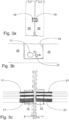
- two floor slabs 26 are set in parallel.
- building service systems include a connection 17, the end 18 of which is arranged to be exposed for part of the distance. The connections can then be connected on the building site.
- the end 18 is arranged in the recess 19 formed in the cast concrete.
- the recesses in the parallel floor slabs are next to each other ( Figure 3a ).
- Figure 3b shows a side view perpendicularly to the connections 17.
- the larger connections are, for example, drain or air-conditioning pipes and the smaller ones electrical conduits or waterpipe casings.
- Figure 3c is a top view.
- the parallel floor slabs are installed with a small gap of, for example, 15 mm.
- the distance between the outermost ribs is then, for example, 60 mm.
- the end 18 of the connection 17 includes a joint part 20 arranged to move, which is arranged to extend to the end 22 of a corresponding connection 21 in another floor slab, to join the connections to each other.
- the connection can then be connected easily, rapidly, and securely.
- the depth of the recess is 180 mm, which is in practice the maximum size of the joint part. This then avoids the joint part protruding outside the external dimensions of the floor slab. With the aforementioned dimensioning, the joint part set in place extends over the ends of both connections by 50 mm, which ensures a tight connection.
- One alternative joint part 20 is a muff, which is external in Figure 4 .
- the muff can also be internal. In the muff there is preferably sealing and, if necessary, also tensioning means.
- the muff's position in the finished flooring deck is shown by a broken-line rectangle.
- the rib is cut and a separate casting wall 23 is made to limit the recess.
- the casting wall supports the connections and also prevents the insulation from leaking out.
- the building service systems are left partly exposed and after connecting the building service systems of adjacent floor slabs the exposed parts are covered with concrete. In other words, the recesses 19 of Figure 4 and the gap between the floor slabs are filled with a single casting.
- Rigid connections such as drain and air-conditioning pipes, must be aligned sufficiently precisely for the joint part to be able to be moved into place.
- Flexible electrical conduits and waterpipe casings permit a slightly greater tolerance.
- this alignment is taken into account and otherwise too it is sought to minimize the number of joints.
- the entire flooring deck and the floor slabs it demands are planned beforehand and the floor slabs are made at the factory read for installation. According to the invention, separate joint parts are used, which are installed when forming the deck.
- the ends of the floor slab must be closed.
- slipforming conventional formwork is avoided. Moulds are mainly only used at the recesses.
- a two-part mould is placed, by which the end walls of two consecutive slipformed floor slabs are cast. The end walls become part of the composite structure.
- the concrete casting is formed by slipforming, from which the floor slab is separated by sawing.
- the diagonally shaded areas depict the end walls, which are separated from each other by sawing. Sawing can even be done only after the casting of the cover.
- the thickness of the example slab shown in Figure 5 is 350 mm. Equipped with prestressed reinforcing strands, the span can be chosen to be as much as 12 000 mm.
- the width of the floor slab 26 is increased at the same time to be 2400 mm. This is then a considerably larger slab than a normal hollow-core slab.
- the floor slab shown is, however, suitable for transportation using normal equipment and can even be handled on site, though the floor slab weighs nearly thirteen tonnes.
- the lower and upper strands and the cover casting mesh are joined together by dowels.
- the same reference numbers are used for parts that are functionally the same.
- the space left over from building service systems is filled with a suitable material, when the cover can be cast. Sound and thermal insulation also improves.
- the space in the hollow cores can be filled with an insulating material, such as mineral wool or polyurethane. However these are expensive and placing them takes time. Some insulating material may be combustible, which increase the fire load. Preferably a spreadable and non-combustible material is used.
- Various lightweight concretes are possible. These harden when drying and lock the building service systems in place. In lightweight concrete, the filler can be expended clay or styrox, i.e. the aforesaid EPS. When using expanded-clay concrete, protective fabric is not needed.
- crushed foamed glass is used, which is even lighter than lightweight concrete.
- crushed foamed glass spreads into even small holes, but does not harden. Thus in cases of possible damage the building service systems can be drilled out and locally repaired. Crushed foamed glass is then easy to remove.
- crushed foamed glass is non-combustible and easily recycled. After compaction, the cover can be cast on top of the crushed foamed glass.
- the ribbed slab together with the reinforcing steel is cast first. After sufficient drying, the building service systems are installed and the remaining spaces are filled with a material, such as the aforesaid crushed foamed glass. Finally the cover is cast with reinforcing mesh. If necessary, protective fabric strips or similar are used under the cover casting to prevent the cover casting seeping into the insulation. After the casting has dried sufficiently, the tension in the reinforcement is released and the tightness and joints of the connections are checked and protected during storage and transporting.
- FIG 6a the air-conditioning pipes 15 are in two different places.
- Figures 6a, 6b , and 7 also show the socket anchors 27, to which the lifting chains are attached.
- the socket anchor 27 is cast between the ribs 16 as part of the floor slab 26. In the casting of the cover 11, the head of the socket anchor 27 remains in the recess. Nevertheless, the connecting part can be threaded through the head of the socket anchor. The floor slab can then be safely lifted by four socket anchors.
- each floor slab is installed in a preplanned location and position. The protection is removed and the connections connected and the floor slabs are cast in.
- essentially all the feed-ins inside a floor are implemented using connections inside the floor slab. This avoids separate reservations and ducts for building service systems. The making of lines and ducts on the building site is also eliminated. Between floors, one or more vertical ducts are used, the connections in which being connected to the connections coming from the deck. More generally, in a building formed of floor slabs according to the invention, a feed point 29 ( Figure 8 ) is arranged for the building service systems formed from the floor slabs 26 joined to the floor 28.
- the hot-water line is connected to a pipe in the floor slab, which extends to the area of the deck. Similarly, the other connections are connected, so that the entire floor's deck is taken care of in a centralized manner.
- the drainpipes and exhaust-air ducts also come to the feed point.
- the feed point 29 is preferably formed by a shaft 30, which is arranged separately from other spaces. The building service systems can then be easily isolated and monitored. Adjustments and maintenance are also easy to do.
- the outline of the shaft 30 is emphasized with a thick line.
- the shaft 30 extends to the various floors of the building. Then, for example, replacement air can be distributed from the air-conditioning room through the ducts run in the shaft to the air-conditioning ducts in the decks of the various floors.
- Figure 8 shows schematically a part of a building that is formed of the floor slabs 26 according to the invention.
- Each floor slab 26 extends from a window 34 to the plane of the lift shafts 33.
- Next to the lift shafts 33 is a shaft 30 according to the invention.
- the deck is designed for each object, so that the connections are at the desired locations.
- the replacement-air ducts are placed to open near the window's 34 surface.
- the air-conditioning pipes being inside the floor slab 26, the replacement-air device can be placed on the lower surface of the floor slab.
- the installation height remains low and the replacement air spreads evenly to a wide area.
- the replacement air is preferably directed towards the window surface, thus preventing misting of the windows.
- the replacement-air pipe 15 is lowest in Figure 8 and initially it has a size of 160 mm. The final part has a size of 100 mm and the replacement-air pipe opens close to the windows 34.
- Figure 9 shows a side view of the same part of the building.
- a replacement-air pipe 15 is shown, which open near the surface of the window 34.
- an exhaust-air pipe is shown.
- On the first floor are domestic-water pipes, which descend from the ceiling to a suitable height. In the shaft 30, each connection is connected to the vertical ducts.
- the floor slab can also be used installed at a slant arranged as a ceiling.
- the building service systems then contain mainly electrical cables and air-conditioning ducts, which would be difficult to implement if made in the known manner.
- the structure of the floor slab according to the invention is a prestressed slab element, which is cast in two parts.
- the lower part, in which the prestressed reinforcement strands are located, is cast first.
- the prestressed strands are located in the area of the ribs, so that feed-throughs can be made in the hollow cores.
- the piping is installed and the cores are filled, for example with EPS concrete.
- the cover is reinforced and cast.
- the deck formed of floor slabs is connected to the local district-heating network.
- the heating and cooling system is water-circulation radiation heating.
- the main heating pipes are steel pipes to be threaded or welded in the shaft and the main cooling pipes are copper or steel pipes.
- the distribution pipes coming from the headers in the floor slabs are of PEX piping in casings.
- Water and drain lines are connected to the network of the local waterworks. Networks for cold and hot domestic water and warm circulating water are made in the building.
- the main pipes of the domestic-water network are of copper and the distribution lines in the elements after the headers are of encased PEX piping. In the vertical rises there are leak detectors.
- the material of the drainpipes is plastic, that of the exposed drains is cast iron or stainless steel.
- the drains of the water furnishings are run mainly inside the floor slab.
- the building has a distributed replacement and exhaust-air ventilation system equipped with heat recovery.
- the main ducts of the ventilation system run a separate shaft built on site and the horizontal runs are inside the floor slab, in accordance with the invention.
- the material is galvanized steel.
- the diameter of the duct running inside the floor slab can be as much as 160 mm. Nevertheless it has space to cross over the other pipes of the system.
- the replacement and exhaust ducts run in parallel in the floor slab.
- the terminal devices of the ventilation are installed, for example, in the cover plate of a radiator panel.
- the replacement-air duct extends to close to the window surface. Window misting problems are then avoided. This is important, especially in passive buildings, in which air and heat leaks are minimized.
- the exhaust-air duct is placed to open at a different location sufficiently far from the replacement-air duct.
Landscapes
- Engineering & Computer Science (AREA)
- Architecture (AREA)
- Structural Engineering (AREA)
- Physics & Mathematics (AREA)
- Electromagnetism (AREA)
- Civil Engineering (AREA)
- Chemical & Material Sciences (AREA)
- Ceramic Engineering (AREA)
- Mechanical Engineering (AREA)
- Manufacturing & Machinery (AREA)
- Building Environments (AREA)
- Floor Finish (AREA)
Claims (11)
- Bodenplatte, die dazu bestimmt ist, einen Bodenbelag zu bilden, und wobei die Bodenplatte (26) gegossenen Beton in Form einer tragenden Hohlkernstruktur aufweist, die eine Längsverstärkung (12) verwendet, wobei der gegossene Beton eine gerippte Betonplatte (10) einschließt und die Verstärkung (12) vorgespannt ist und die gerippte Betonplatte (10) eine gegossene Abdeckung (11) aufweist, die die gerippte Betonplatte (10) verschließt, wobei die gerippte Platte (10) und die Abdeckung (11) separat unter Verwendung von Gleitformen gegossen sind, dadurch gekennzeichnet, dass die Bodenplatte (26) haustechnische Systeme einschließt, und die haustechnischen Systeme so angeordnet sind, dass sie in den hohlen Kernen (13) der Hohlkernstruktur ausgebildet sind, und die haustechnischen Systeme eine Verbindung (17) einschließen, deren eines Ende (18) so angeordnet ist, dass es über einen Teil des Abstands freiliegt, und dass die Verbindung (17) eine Klimatisierungsleitung (15) ist und das Ende (18) der Verbindung (17) einen beweglichen Gelenkteil (20) einschließt, der so angeordnet ist, dass er sich zum Ende (22) einer entsprechenden Verbindung (21) erstreckt, die zu einer anderen Bodenplatte gehört, um die Verbindungen miteinander zu verbinden.
- Bodenplatte nach Anspruch 1, dadurch gekennzeichnet, dass in den hohlen Kernen (13) der gebildeten Hohlkernstruktur eine Isolierung (14) angeordnet ist, die aus zerkleinertem Schaumglas oder einem anderen ähnlichen Streumaterial besteht.
- Bodenplatte nach Anspruch 1 oder 2, dadurch gekennzeichnet, dass das Ende (18) in einer im gegossenen Beton ausgebildeten Vertiefung (19) angeordnet ist.
- Bodenplatte nach einem der Ansprüche 1 bis 3, dadurch gekennzeichnet, dass die Klimatisierungsleitung (15) aus zwei kleinen Leitungen (24, 25) gebildet ist.
- Verfahren zum Herstellen eines Bodenbelags, bei dem der Bodenbelag aus mehreren Bodenplatten (26) nach einem der Ansprüche 1 bis 4 gebildet wird, die gegossenen Beton in Form einer lasttragenden Hohlkernstruktur mit einer Längsverstärkung (12) einschließen, wobei der gegossene Beton eine gerippte Betonplatte (10) einschließt und der gegossene Beton durch erstes Gießen durch Gleitformen einer gerippten Betonplatte (10) gebildet wird, wenn die Verstärkung (12) vorgespannt ist, die durch separates Gießen einer Abdeckung (11) geschlossen wird, um die lasttragende Hohlkernstruktur zu bilden, dadurch gekennzeichnet, dass die Bodenplatte (26) haustechnische Systeme einschließt, die in den hohlen Kernen (13) angeordnet sind, bevor die Abdeckung (11) durch Gleitformen gegossen wird, wobei die haustechnischen Systeme eine Verbindung (17) einschließen, deren Ende (18) so angeordnet ist, dass es für einen Teil des Abstands freigelegt ist, und dass die Verbindung (17) eine Klimatisierungsleitung (15) ist, wobei das Ende (18) der Verbindung (17) einen beweglichen Gelenkteil (20) einschließt, der so angeordnet ist, dass er sich bis zum Ende (22) einer entsprechenden Verbindung (21) erstreckt, die zu einer anderen Bodenplatte gehört, um die Verbindungen miteinander zu verbinden.
- Verfahren nach Anspruch 5, dadurch gekennzeichnet, dass nach dem Anordnen der haustechnischen Systeme vor dem Gießen der Abdeckung (11) die gerippte Platte (10) mit einer Streuisolierung (14) gefüllt wird.
- Verfahren nach Anspruch 5 oder 6, dadurch gekennzeichnet, dass der gegossene Beton durch Gleitformen gegossen wird, von denen die Bodenplatte durch Sägen getrennt wird.
- Verfahren nach einem der Ansprüche 5 bis 7, dadurch gekennzeichnet, dass die haustechnischen Systeme teilweise freigelegt werden, und dass nach der Verbindung der haustechnischen Systeme der parallelen Bodenplatten (26) die freigelegten Teile mit gegossenem Beton abgedeckt werden.
- Gebäude gebildet aus Bodenplatten nach einem der Ansprüche 1 bis 4, dadurch gekennzeichnet, dass ein Zuführungspunkt (29) für die im Boden (28) von zusammengefügten Bodenplatten (26) gebildeten haustechnischen Systeme angeordnet ist.
- Gebäude nach Anspruch 9, dadurch gekennzeichnet, dass sich die Zuführungsstelle (29) in einem Schacht (30) befindet, der getrennt von den übrigen Räumen angeordnet ist.
- Gebäude nach Anspruch 10, dadurch gekennzeichnet, dass sich der Schacht (30) bis zu den verschiedenen Böden (28) des Gebäudes erstreckt.
Applications Claiming Priority (1)
| Application Number | Priority Date | Filing Date | Title |
|---|---|---|---|
| FI20185078 | 2018-01-29 |
Publications (3)
| Publication Number | Publication Date |
|---|---|
| EP3517698A1 EP3517698A1 (de) | 2019-07-31 |
| EP3517698B1 true EP3517698B1 (de) | 2024-05-29 |
| EP3517698C0 EP3517698C0 (de) | 2024-05-29 |
Family
ID=65861188
Family Applications (1)
| Application Number | Title | Priority Date | Filing Date |
|---|---|---|---|
| EP19154203.4A Active EP3517698B1 (de) | 2018-01-29 | 2019-01-29 | Vorgefertigte bodenplatte und verfahren zur herstellung eines bodenbelags und gebäude aus vorgefertigten bodenplatten |
Country Status (1)
| Country | Link |
|---|---|
| EP (1) | EP3517698B1 (de) |
Cited By (1)
| Publication number | Priority date | Publication date | Assignee | Title |
|---|---|---|---|---|
| EP4628670A1 (de) | 2024-04-03 | 2025-10-08 | SBS Betoni Oy | Fertigplatte, verfahren zur herstellung einer fertigplatte und gebäude aus fertigplatten |
Families Citing this family (4)
| Publication number | Priority date | Publication date | Assignee | Title |
|---|---|---|---|---|
| CN108590005B (zh) * | 2018-04-20 | 2019-05-24 | 长安大学 | 一种装配整体式暗梁空心双向楼盖及装配方法 |
| FI129460B (en) | 2019-02-12 | 2022-02-28 | Elematic Oyj | Method for manufacturing prefabricated concrete products |
| CN113309282A (zh) * | 2021-06-11 | 2021-08-27 | 中电建十一局工程有限公司 | 一种空心楼板施工工艺 |
| CN115095075A (zh) * | 2022-07-28 | 2022-09-23 | 成都市建筑设计研究院有限公司 | 一种能够容纳设备管线的不规则曲面混凝土楼盖板 |
Family Cites Families (3)
| Publication number | Priority date | Publication date | Assignee | Title |
|---|---|---|---|---|
| US3994639A (en) * | 1973-01-11 | 1976-11-30 | Hewitt Frederick M | Apparatus for extruding concrete |
| DE3006672A1 (de) * | 1980-02-22 | 1981-09-10 | Otto 6000 Frankfurt Ruppmann | Hohlkoerper-bauelement aus stahlbeton |
| CH699439B1 (de) * | 2007-06-05 | 2010-03-15 | Mueller Ernst Kg | Fertigelement für den Trockenbau. |
-
2019
- 2019-01-29 EP EP19154203.4A patent/EP3517698B1/de active Active
Cited By (1)
| Publication number | Priority date | Publication date | Assignee | Title |
|---|---|---|---|---|
| EP4628670A1 (de) | 2024-04-03 | 2025-10-08 | SBS Betoni Oy | Fertigplatte, verfahren zur herstellung einer fertigplatte und gebäude aus fertigplatten |
Also Published As
| Publication number | Publication date |
|---|---|
| EP3517698A1 (de) | 2019-07-31 |
| EP3517698C0 (de) | 2024-05-29 |
Similar Documents
| Publication | Publication Date | Title |
|---|---|---|
| EP3517698B1 (de) | Vorgefertigte bodenplatte und verfahren zur herstellung eines bodenbelags und gebäude aus vorgefertigten bodenplatten | |
| US7100336B2 (en) | Concrete building panel with a low density core and carbon fiber and steel reinforcement | |
| US20210301528A1 (en) | Systems and methods for constructing a single-storey building | |
| US6536168B1 (en) | Apparatus and methods for moldable and customizable structures | |
| US6119417A (en) | Sloped concrete roof systems | |
| EP2483488B1 (de) | Bauwerk mit vorgefertigten gerippten paneelen | |
| EP0880627B1 (de) | Boden- und deckenstrukturen | |
| US20070144093A1 (en) | Method and apparatus for fabricating a low density wall panel with interior surface finished | |
| US6845591B1 (en) | Hollow-core slab for forming a floor field in which ducts can be incorporated, and method for forming a floor field with ducts using such hollow-core slabs | |
| CN106368358A (zh) | 模块化集成楼板及房屋 | |
| KR100284894B1 (ko) | 경량단열패널을 이용한 온돌바닥구조 | |
| EP2495376A1 (de) | Zwischendecke und ein Verfahren zum Zirkulieren von Luft in der Zwischendecke | |
| EP1258574B1 (de) | Tragende Verbundplatte für Gebäude | |
| IE86668B1 (en) | Structural panel and a building structure formed therefrom | |
| RU2119020C1 (ru) | Многоэтажное здание со стенами из мелкоштучных камней и способ его возведения | |
| RU2796099C1 (ru) | Типовой модуль крупнопанельного здания | |
| JP7051358B2 (ja) | プレキャスト合成スラブ、拡幅用プレート、及びプレキャスト合成スラブを用いた床構造、並びに建物 | |
| RU2780187C1 (ru) | Способ сооружения узла цокольного перекрытия с колонной над холодными и проветриваемыми подпольями | |
| RU2806208C1 (ru) | Способ сооружения узла несущей стены из бетонных блоков и монолитного цокольного перекрытия над холодными или проветриваемыми подпольями | |
| CN216586666U (zh) | 综合管廊通风投料节点结构及综合管廊系统 | |
| KR100711021B1 (ko) | 천정마감재를 겸한 콘크리트 슬래브 거푸집 공법 | |
| US20250237056A1 (en) | Wall panel with window aperture | |
| RU2799676C1 (ru) | Способ сопряжения стены из легких стальных тонкостенных конструкций с цокольным перекрытием над проветриваемыми и холодными подпольями | |
| EP3334867A1 (de) | Fertiggebäudesystem | |
| EA052544B1 (ru) | Многослойная стеновая панель |
Legal Events
| Date | Code | Title | Description |
|---|---|---|---|
| PUAI | Public reference made under article 153(3) epc to a published international application that has entered the european phase |
Free format text: ORIGINAL CODE: 0009012 |
|
| STAA | Information on the status of an ep patent application or granted ep patent |
Free format text: STATUS: THE APPLICATION HAS BEEN PUBLISHED |
|
| AK | Designated contracting states |
Kind code of ref document: A1 Designated state(s): AL AT BE BG CH CY CZ DE DK EE ES FI FR GB GR HR HU IE IS IT LI LT LU LV MC MK MT NL NO PL PT RO RS SE SI SK SM TR |
|
| AX | Request for extension of the european patent |
Extension state: BA ME |
|
| STAA | Information on the status of an ep patent application or granted ep patent |
Free format text: STATUS: REQUEST FOR EXAMINATION WAS MADE |
|
| 17P | Request for examination filed |
Effective date: 20200129 |
|
| RBV | Designated contracting states (corrected) |
Designated state(s): AL AT BE BG CH CY CZ DE DK EE ES FI FR GB GR HR HU IE IS IT LI LT LU LV MC MK MT NL NO PL PT RO RS SE SI SK SM TR |
|
| STAA | Information on the status of an ep patent application or granted ep patent |
Free format text: STATUS: EXAMINATION IS IN PROGRESS |
|
| 17Q | First examination report despatched |
Effective date: 20220309 |
|
| RIN1 | Information on inventor provided before grant (corrected) |
Inventor name: SUUTARINEN, TIMO |
|
| GRAP | Despatch of communication of intention to grant a patent |
Free format text: ORIGINAL CODE: EPIDOSNIGR1 |
|
| STAA | Information on the status of an ep patent application or granted ep patent |
Free format text: STATUS: GRANT OF PATENT IS INTENDED |
|
| RIC1 | Information provided on ipc code assigned before grant |
Ipc: E04C 3/26 20060101ALN20231213BHEP Ipc: B28B 3/22 20060101ALN20231213BHEP Ipc: E04B 5/48 20060101ALI20231213BHEP Ipc: E04B 5/26 20060101ALI20231213BHEP Ipc: E04B 5/04 20060101AFI20231213BHEP |
|
| INTG | Intention to grant announced |
Effective date: 20240108 |
|
| GRAS | Grant fee paid |
Free format text: ORIGINAL CODE: EPIDOSNIGR3 |
|
| GRAA | (expected) grant |
Free format text: ORIGINAL CODE: 0009210 |
|
| STAA | Information on the status of an ep patent application or granted ep patent |
Free format text: STATUS: THE PATENT HAS BEEN GRANTED |
|
| AK | Designated contracting states |
Kind code of ref document: B1 Designated state(s): AL AT BE BG CH CY CZ DE DK EE ES FI FR GB GR HR HU IE IS IT LI LT LU LV MC MK MT NL NO PL PT RO RS SE SI SK SM TR |
|
| REG | Reference to a national code |
Ref country code: CH Ref legal event code: EP |
|
| REG | Reference to a national code |
Ref country code: IE Ref legal event code: FG4D |
|
| REG | Reference to a national code |
Ref country code: DE Ref legal event code: R096 Ref document number: 602019052820 Country of ref document: DE |
|
| U01 | Request for unitary effect filed |
Effective date: 20240625 |
|
| U07 | Unitary effect registered |
Designated state(s): AT BE BG DE DK EE FI FR IT LT LU LV MT NL PT SE SI Effective date: 20240704 |
|
| PG25 | Lapsed in a contracting state [announced via postgrant information from national office to epo] |
Ref country code: IS Free format text: LAPSE BECAUSE OF FAILURE TO SUBMIT A TRANSLATION OF THE DESCRIPTION OR TO PAY THE FEE WITHIN THE PRESCRIBED TIME-LIMIT Effective date: 20240929 |
|
| PG25 | Lapsed in a contracting state [announced via postgrant information from national office to epo] |
Ref country code: HR Free format text: LAPSE BECAUSE OF FAILURE TO SUBMIT A TRANSLATION OF THE DESCRIPTION OR TO PAY THE FEE WITHIN THE PRESCRIBED TIME-LIMIT Effective date: 20240529 |
|
| PG25 | Lapsed in a contracting state [announced via postgrant information from national office to epo] |
Ref country code: GR Free format text: LAPSE BECAUSE OF FAILURE TO SUBMIT A TRANSLATION OF THE DESCRIPTION OR TO PAY THE FEE WITHIN THE PRESCRIBED TIME-LIMIT Effective date: 20240830 |
|
| PG25 | Lapsed in a contracting state [announced via postgrant information from national office to epo] |
Ref country code: ES Free format text: LAPSE BECAUSE OF FAILURE TO SUBMIT A TRANSLATION OF THE DESCRIPTION OR TO PAY THE FEE WITHIN THE PRESCRIBED TIME-LIMIT Effective date: 20240529 |
|
| PG25 | Lapsed in a contracting state [announced via postgrant information from national office to epo] |
Ref country code: PL Free format text: LAPSE BECAUSE OF FAILURE TO SUBMIT A TRANSLATION OF THE DESCRIPTION OR TO PAY THE FEE WITHIN THE PRESCRIBED TIME-LIMIT Effective date: 20240529 |
|
| PG25 | Lapsed in a contracting state [announced via postgrant information from national office to epo] |
Ref country code: PL Free format text: LAPSE BECAUSE OF FAILURE TO SUBMIT A TRANSLATION OF THE DESCRIPTION OR TO PAY THE FEE WITHIN THE PRESCRIBED TIME-LIMIT Effective date: 20240529 Ref country code: IS Free format text: LAPSE BECAUSE OF FAILURE TO SUBMIT A TRANSLATION OF THE DESCRIPTION OR TO PAY THE FEE WITHIN THE PRESCRIBED TIME-LIMIT Effective date: 20240929 Ref country code: HR Free format text: LAPSE BECAUSE OF FAILURE TO SUBMIT A TRANSLATION OF THE DESCRIPTION OR TO PAY THE FEE WITHIN THE PRESCRIBED TIME-LIMIT Effective date: 20240529 Ref country code: GR Free format text: LAPSE BECAUSE OF FAILURE TO SUBMIT A TRANSLATION OF THE DESCRIPTION OR TO PAY THE FEE WITHIN THE PRESCRIBED TIME-LIMIT Effective date: 20240830 Ref country code: ES Free format text: LAPSE BECAUSE OF FAILURE TO SUBMIT A TRANSLATION OF THE DESCRIPTION OR TO PAY THE FEE WITHIN THE PRESCRIBED TIME-LIMIT Effective date: 20240529 Ref country code: RS Free format text: LAPSE BECAUSE OF FAILURE TO SUBMIT A TRANSLATION OF THE DESCRIPTION OR TO PAY THE FEE WITHIN THE PRESCRIBED TIME-LIMIT Effective date: 20240829 |
|
| PG25 | Lapsed in a contracting state [announced via postgrant information from national office to epo] |
Ref country code: CZ Free format text: LAPSE BECAUSE OF FAILURE TO SUBMIT A TRANSLATION OF THE DESCRIPTION OR TO PAY THE FEE WITHIN THE PRESCRIBED TIME-LIMIT Effective date: 20240529 |
|
| PG25 | Lapsed in a contracting state [announced via postgrant information from national office to epo] |
Ref country code: RO Free format text: LAPSE BECAUSE OF FAILURE TO SUBMIT A TRANSLATION OF THE DESCRIPTION OR TO PAY THE FEE WITHIN THE PRESCRIBED TIME-LIMIT Effective date: 20240529 Ref country code: SK Free format text: LAPSE BECAUSE OF FAILURE TO SUBMIT A TRANSLATION OF THE DESCRIPTION OR TO PAY THE FEE WITHIN THE PRESCRIBED TIME-LIMIT Effective date: 20240529 |
|
| PG25 | Lapsed in a contracting state [announced via postgrant information from national office to epo] |
Ref country code: SM Free format text: LAPSE BECAUSE OF FAILURE TO SUBMIT A TRANSLATION OF THE DESCRIPTION OR TO PAY THE FEE WITHIN THE PRESCRIBED TIME-LIMIT Effective date: 20240529 |
|
| PG25 | Lapsed in a contracting state [announced via postgrant information from national office to epo] |
Ref country code: SM Free format text: LAPSE BECAUSE OF FAILURE TO SUBMIT A TRANSLATION OF THE DESCRIPTION OR TO PAY THE FEE WITHIN THE PRESCRIBED TIME-LIMIT Effective date: 20240529 Ref country code: SK Free format text: LAPSE BECAUSE OF FAILURE TO SUBMIT A TRANSLATION OF THE DESCRIPTION OR TO PAY THE FEE WITHIN THE PRESCRIBED TIME-LIMIT Effective date: 20240529 Ref country code: RO Free format text: LAPSE BECAUSE OF FAILURE TO SUBMIT A TRANSLATION OF THE DESCRIPTION OR TO PAY THE FEE WITHIN THE PRESCRIBED TIME-LIMIT Effective date: 20240529 Ref country code: CZ Free format text: LAPSE BECAUSE OF FAILURE TO SUBMIT A TRANSLATION OF THE DESCRIPTION OR TO PAY THE FEE WITHIN THE PRESCRIBED TIME-LIMIT Effective date: 20240529 |
|
| U20 | Renewal fee for the european patent with unitary effect paid |
Year of fee payment: 7 Effective date: 20250122 |
|
| PLBE | No opposition filed within time limit |
Free format text: ORIGINAL CODE: 0009261 |
|
| STAA | Information on the status of an ep patent application or granted ep patent |
Free format text: STATUS: NO OPPOSITION FILED WITHIN TIME LIMIT |
|
| 26N | No opposition filed |
Effective date: 20250303 |
|
| REG | Reference to a national code |
Ref country code: CH Ref legal event code: PL |
|
| PG25 | Lapsed in a contracting state [announced via postgrant information from national office to epo] |
Ref country code: MC Free format text: LAPSE BECAUSE OF FAILURE TO SUBMIT A TRANSLATION OF THE DESCRIPTION OR TO PAY THE FEE WITHIN THE PRESCRIBED TIME-LIMIT Effective date: 20240529 |
|
| GBPC | Gb: european patent ceased through non-payment of renewal fee |
Effective date: 20250129 |
|
| PG25 | Lapsed in a contracting state [announced via postgrant information from national office to epo] |
Ref country code: GB Free format text: LAPSE BECAUSE OF NON-PAYMENT OF DUE FEES Effective date: 20250129 |
|
| PG25 | Lapsed in a contracting state [announced via postgrant information from national office to epo] |
Ref country code: CH Free format text: LAPSE BECAUSE OF NON-PAYMENT OF DUE FEES Effective date: 20250131 |
|
| PG25 | Lapsed in a contracting state [announced via postgrant information from national office to epo] |
Ref country code: IE Free format text: LAPSE BECAUSE OF NON-PAYMENT OF DUE FEES Effective date: 20250129 |
|
| U20 | Renewal fee for the european patent with unitary effect paid |
Year of fee payment: 8 Effective date: 20260126 |
|
| PGFP | Annual fee paid to national office [announced via postgrant information from national office to epo] |
Ref country code: NO Payment date: 20260123 Year of fee payment: 8 |