EP3517732B1 - Aube composite renforcé et procédé de fabrication d'une aube - Google Patents
Aube composite renforcé et procédé de fabrication d'une aube Download PDFInfo
- Publication number
- EP3517732B1 EP3517732B1 EP19153804.0A EP19153804A EP3517732B1 EP 3517732 B1 EP3517732 B1 EP 3517732B1 EP 19153804 A EP19153804 A EP 19153804A EP 3517732 B1 EP3517732 B1 EP 3517732B1
- Authority
- EP
- European Patent Office
- Prior art keywords
- blade
- fiber plies
- spanwise
- composite fiber
- plies
- Prior art date
- Legal status (The legal status is an assumption and is not a legal conclusion. Google has not performed a legal analysis and makes no representation as to the accuracy of the status listed.)
- Active
Links
Images




Classifications
-
- B—PERFORMING OPERATIONS; TRANSPORTING
- B29—WORKING OF PLASTICS; WORKING OF SUBSTANCES IN A PLASTIC STATE IN GENERAL
- B29D—PRODUCING PARTICULAR ARTICLES FROM PLASTICS OR FROM SUBSTANCES IN A PLASTIC STATE
- B29D99/00—Subject matter not provided for in other groups of this subclass
- B29D99/0025—Producing blades or the like, e.g. blades for turbines, propellers, or wings
-
- F—MECHANICAL ENGINEERING; LIGHTING; HEATING; WEAPONS; BLASTING
- F01—MACHINES OR ENGINES IN GENERAL; ENGINE PLANTS IN GENERAL; STEAM ENGINES
- F01D—NON-POSITIVE DISPLACEMENT MACHINES OR ENGINES, e.g. STEAM TURBINES
- F01D5/00—Blades; Blade-carrying members; Heating, heat-insulating, cooling or antivibration means on the blades or the members
- F01D5/12—Blades
- F01D5/14—Form or construction
- F01D5/147—Construction, i.e. structural features, e.g. of weight-saving hollow blades
-
- B—PERFORMING OPERATIONS; TRANSPORTING
- B29—WORKING OF PLASTICS; WORKING OF SUBSTANCES IN A PLASTIC STATE IN GENERAL
- B29C—SHAPING OR JOINING OF PLASTICS; SHAPING OF MATERIAL IN A PLASTIC STATE, NOT OTHERWISE PROVIDED FOR; AFTER-TREATMENT OF THE SHAPED PRODUCTS, e.g. REPAIRING
- B29C70/00—Shaping composites, i.e. plastics material comprising reinforcements, fillers or preformed parts, e.g. inserts
- B29C70/04—Shaping composites, i.e. plastics material comprising reinforcements, fillers or preformed parts, e.g. inserts comprising reinforcements only, e.g. self-reinforcing plastics
- B29C70/28—Shaping operations therefor
- B29C70/30—Shaping by lay-up, i.e. applying fibres, tape or broadsheet on a mould, former or core; Shaping by spray-up, i.e. spraying of fibres on a mould, former or core
- B29C70/302—Details of the edges of fibre composites, e.g. edge finishing or means to avoid delamination
-
- B—PERFORMING OPERATIONS; TRANSPORTING
- B32—LAYERED PRODUCTS
- B32B—LAYERED PRODUCTS, i.e. PRODUCTS BUILT-UP OF STRATA OF FLAT OR NON-FLAT, e.g. CELLULAR OR HONEYCOMB, FORM
- B32B27/00—Layered products comprising a layer of synthetic resin
- B32B27/06—Layered products comprising a layer of synthetic resin as the main or only constituent of a layer, which is next to another layer of the same or of a different material
- B32B27/08—Layered products comprising a layer of synthetic resin as the main or only constituent of a layer, which is next to another layer of the same or of a different material of synthetic resin
-
- B—PERFORMING OPERATIONS; TRANSPORTING
- B32—LAYERED PRODUCTS
- B32B—LAYERED PRODUCTS, i.e. PRODUCTS BUILT-UP OF STRATA OF FLAT OR NON-FLAT, e.g. CELLULAR OR HONEYCOMB, FORM
- B32B3/00—Layered products comprising a layer with external or internal discontinuities or unevennesses, or a layer of non-planar shape; Layered products comprising a layer having particular features of form
- B32B3/10—Layered products comprising a layer with external or internal discontinuities or unevennesses, or a layer of non-planar shape; Layered products comprising a layer having particular features of form characterised by a discontinuous layer, i.e. formed of separate pieces of material
- B32B3/14—Layered products comprising a layer with external or internal discontinuities or unevennesses, or a layer of non-planar shape; Layered products comprising a layer having particular features of form characterised by a discontinuous layer, i.e. formed of separate pieces of material characterised by a face layer formed of separate pieces of material which are juxtaposed side-by-side
-
- B—PERFORMING OPERATIONS; TRANSPORTING
- B32—LAYERED PRODUCTS
- B32B—LAYERED PRODUCTS, i.e. PRODUCTS BUILT-UP OF STRATA OF FLAT OR NON-FLAT, e.g. CELLULAR OR HONEYCOMB, FORM
- B32B5/00—Layered products characterised by the non- homogeneity or physical structure, i.e. comprising a fibrous, filamentary, particulate or foam layer; Layered products characterised by having a layer differing constitutionally or physically in different parts
- B32B5/02—Layered products characterised by the non- homogeneity or physical structure, i.e. comprising a fibrous, filamentary, particulate or foam layer; Layered products characterised by having a layer differing constitutionally or physically in different parts characterised by structural features of a fibrous or filamentary layer
- B32B5/12—Layered products characterised by the non- homogeneity or physical structure, i.e. comprising a fibrous, filamentary, particulate or foam layer; Layered products characterised by having a layer differing constitutionally or physically in different parts characterised by structural features of a fibrous or filamentary layer characterised by the relative arrangement of fibres or filaments of different layers, e.g. the fibres or filaments being parallel or perpendicular to each other
-
- B—PERFORMING OPERATIONS; TRANSPORTING
- B32—LAYERED PRODUCTS
- B32B—LAYERED PRODUCTS, i.e. PRODUCTS BUILT-UP OF STRATA OF FLAT OR NON-FLAT, e.g. CELLULAR OR HONEYCOMB, FORM
- B32B5/00—Layered products characterised by the non- homogeneity or physical structure, i.e. comprising a fibrous, filamentary, particulate or foam layer; Layered products characterised by having a layer differing constitutionally or physically in different parts
- B32B5/22—Layered products characterised by the non- homogeneity or physical structure, i.e. comprising a fibrous, filamentary, particulate or foam layer; Layered products characterised by having a layer differing constitutionally or physically in different parts characterised by the presence of two or more layers which are next to each other and are fibrous, filamentary, formed of particles or foamed
- B32B5/24—Layered products characterised by the non- homogeneity or physical structure, i.e. comprising a fibrous, filamentary, particulate or foam layer; Layered products characterised by having a layer differing constitutionally or physically in different parts characterised by the presence of two or more layers which are next to each other and are fibrous, filamentary, formed of particles or foamed one layer being a fibrous or filamentary layer
- B32B5/26—Layered products characterised by the non- homogeneity or physical structure, i.e. comprising a fibrous, filamentary, particulate or foam layer; Layered products characterised by having a layer differing constitutionally or physically in different parts characterised by the presence of two or more layers which are next to each other and are fibrous, filamentary, formed of particles or foamed one layer being a fibrous or filamentary layer another layer next to it also being fibrous or filamentary
-
- F—MECHANICAL ENGINEERING; LIGHTING; HEATING; WEAPONS; BLASTING
- F01—MACHINES OR ENGINES IN GENERAL; ENGINE PLANTS IN GENERAL; STEAM ENGINES
- F01D—NON-POSITIVE DISPLACEMENT MACHINES OR ENGINES, e.g. STEAM TURBINES
- F01D5/00—Blades; Blade-carrying members; Heating, heat-insulating, cooling or antivibration means on the blades or the members
- F01D5/12—Blades
- F01D5/28—Selecting particular materials; Particular measures relating thereto; Measures against erosion or corrosion
- F01D5/282—Selecting composite materials, e.g. blades with reinforcing filaments
-
- F—MECHANICAL ENGINEERING; LIGHTING; HEATING; WEAPONS; BLASTING
- F04—POSITIVE - DISPLACEMENT MACHINES FOR LIQUIDS; PUMPS FOR LIQUIDS OR ELASTIC FLUIDS
- F04D—NON-POSITIVE-DISPLACEMENT PUMPS
- F04D29/00—Details, component parts, or accessories
- F04D29/26—Rotors specially for elastic fluids
- F04D29/32—Rotors specially for elastic fluids for axial flow pumps
- F04D29/38—Blades
- F04D29/388—Blades characterised by construction
-
- B—PERFORMING OPERATIONS; TRANSPORTING
- B29—WORKING OF PLASTICS; WORKING OF SUBSTANCES IN A PLASTIC STATE IN GENERAL
- B29C—SHAPING OR JOINING OF PLASTICS; SHAPING OF MATERIAL IN A PLASTIC STATE, NOT OTHERWISE PROVIDED FOR; AFTER-TREATMENT OF THE SHAPED PRODUCTS, e.g. REPAIRING
- B29C70/00—Shaping composites, i.e. plastics material comprising reinforcements, fillers or preformed parts, e.g. inserts
- B29C70/04—Shaping composites, i.e. plastics material comprising reinforcements, fillers or preformed parts, e.g. inserts comprising reinforcements only, e.g. self-reinforcing plastics
- B29C70/06—Fibrous reinforcements only
- B29C70/10—Fibrous reinforcements only characterised by the structure of fibrous reinforcements, e.g. hollow fibres
- B29C70/16—Fibrous reinforcements only characterised by the structure of fibrous reinforcements, e.g. hollow fibres using fibres of substantial or continuous length
- B29C70/22—Fibrous reinforcements only characterised by the structure of fibrous reinforcements, e.g. hollow fibres using fibres of substantial or continuous length oriented in at least two directions forming a two-dimensional [2D] structure
- B29C70/228—Fibrous reinforcements only characterised by the structure of fibrous reinforcements, e.g. hollow fibres using fibres of substantial or continuous length oriented in at least two directions forming a two-dimensional [2D] structure the structure being stacked in parallel layers with fibres of adjacent layers crossing at substantial angles
-
- B—PERFORMING OPERATIONS; TRANSPORTING
- B29—WORKING OF PLASTICS; WORKING OF SUBSTANCES IN A PLASTIC STATE IN GENERAL
- B29K—INDEXING SCHEME ASSOCIATED WITH SUBCLASSES B29B, B29C OR B29D, RELATING TO MOULDING MATERIALS OR TO MATERIALS FOR MOULDS, REINFORCEMENTS, FILLERS OR PREFORMED PARTS, e.g. INSERTS
- B29K2307/00—Use of elements other than metals as reinforcement
- B29K2307/04—Carbon
-
- B—PERFORMING OPERATIONS; TRANSPORTING
- B29—WORKING OF PLASTICS; WORKING OF SUBSTANCES IN A PLASTIC STATE IN GENERAL
- B29K—INDEXING SCHEME ASSOCIATED WITH SUBCLASSES B29B, B29C OR B29D, RELATING TO MOULDING MATERIALS OR TO MATERIALS FOR MOULDS, REINFORCEMENTS, FILLERS OR PREFORMED PARTS, e.g. INSERTS
- B29K2309/00—Use of inorganic materials not provided for in groups B29K2303/00 - B29K2307/00, as reinforcement
- B29K2309/08—Glass
-
- B—PERFORMING OPERATIONS; TRANSPORTING
- B29—WORKING OF PLASTICS; WORKING OF SUBSTANCES IN A PLASTIC STATE IN GENERAL
- B29L—INDEXING SCHEME ASSOCIATED WITH SUBCLASS B29C, RELATING TO PARTICULAR ARTICLES
- B29L2031/00—Other particular articles
- B29L2031/08—Blades for rotors, stators, fans, turbines or the like, e.g. screw propellers
-
- B—PERFORMING OPERATIONS; TRANSPORTING
- B32—LAYERED PRODUCTS
- B32B—LAYERED PRODUCTS, i.e. PRODUCTS BUILT-UP OF STRATA OF FLAT OR NON-FLAT, e.g. CELLULAR OR HONEYCOMB, FORM
- B32B2262/00—Composition or structural features of fibres which form a fibrous or filamentary layer or are present as additives
- B32B2262/10—Inorganic fibres
- B32B2262/101—Glass fibres
-
- B—PERFORMING OPERATIONS; TRANSPORTING
- B32—LAYERED PRODUCTS
- B32B—LAYERED PRODUCTS, i.e. PRODUCTS BUILT-UP OF STRATA OF FLAT OR NON-FLAT, e.g. CELLULAR OR HONEYCOMB, FORM
- B32B2262/00—Composition or structural features of fibres which form a fibrous or filamentary layer or are present as additives
- B32B2262/10—Inorganic fibres
- B32B2262/106—Carbon fibres, e.g. graphite fibres
-
- B—PERFORMING OPERATIONS; TRANSPORTING
- B32—LAYERED PRODUCTS
- B32B—LAYERED PRODUCTS, i.e. PRODUCTS BUILT-UP OF STRATA OF FLAT OR NON-FLAT, e.g. CELLULAR OR HONEYCOMB, FORM
- B32B2603/00—Vanes, blades, propellers, rotors with blades
-
- B—PERFORMING OPERATIONS; TRANSPORTING
- B64—AIRCRAFT; AVIATION; COSMONAUTICS
- B64D—EQUIPMENT FOR FITTING IN OR TO AIRCRAFT; FLIGHT SUITS; PARACHUTES; ARRANGEMENT OR MOUNTING OF POWER PLANTS OR PROPULSION TRANSMISSIONS IN AIRCRAFT
- B64D33/00—Arrangement in aircraft of power plant parts or auxiliaries not otherwise provided for
- B64D33/02—Arrangement in aircraft of power plant parts or auxiliaries not otherwise provided for of combustion air intakes
- B64D2033/022—Arrangement in aircraft of power plant parts or auxiliaries not otherwise provided for of combustion air intakes comprising bird or foreign object protections
-
- B—PERFORMING OPERATIONS; TRANSPORTING
- B64—AIRCRAFT; AVIATION; COSMONAUTICS
- B64D—EQUIPMENT FOR FITTING IN OR TO AIRCRAFT; FLIGHT SUITS; PARACHUTES; ARRANGEMENT OR MOUNTING OF POWER PLANTS OR PROPULSION TRANSMISSIONS IN AIRCRAFT
- B64D27/00—Arrangement or mounting of power plants in aircraft; Aircraft characterised by the type or position of power plants
- B64D27/02—Aircraft characterised by the type or position of power plants
- B64D27/16—Aircraft characterised by the type or position of power plants of jet type
-
- B—PERFORMING OPERATIONS; TRANSPORTING
- B64—AIRCRAFT; AVIATION; COSMONAUTICS
- B64D—EQUIPMENT FOR FITTING IN OR TO AIRCRAFT; FLIGHT SUITS; PARACHUTES; ARRANGEMENT OR MOUNTING OF POWER PLANTS OR PROPULSION TRANSMISSIONS IN AIRCRAFT
- B64D33/00—Arrangement in aircraft of power plant parts or auxiliaries not otherwise provided for
- B64D33/02—Arrangement in aircraft of power plant parts or auxiliaries not otherwise provided for of combustion air intakes
-
- F—MECHANICAL ENGINEERING; LIGHTING; HEATING; WEAPONS; BLASTING
- F05—INDEXING SCHEMES RELATING TO ENGINES OR PUMPS IN VARIOUS SUBCLASSES OF CLASSES F01-F04
- F05D—INDEXING SCHEME FOR ASPECTS RELATING TO NON-POSITIVE-DISPLACEMENT MACHINES OR ENGINES, GAS-TURBINES OR JET-PROPULSION PLANTS
- F05D2220/00—Application
- F05D2220/30—Application in turbines
- F05D2220/36—Application in turbines specially adapted for the fan of turbofan engines
-
- F—MECHANICAL ENGINEERING; LIGHTING; HEATING; WEAPONS; BLASTING
- F05—INDEXING SCHEMES RELATING TO ENGINES OR PUMPS IN VARIOUS SUBCLASSES OF CLASSES F01-F04
- F05D—INDEXING SCHEME FOR ASPECTS RELATING TO NON-POSITIVE-DISPLACEMENT MACHINES OR ENGINES, GAS-TURBINES OR JET-PROPULSION PLANTS
- F05D2300/00—Materials; Properties thereof
- F05D2300/60—Properties or characteristics given to material by treatment or manufacturing
- F05D2300/603—Composites; e.g. fibre-reinforced
- F05D2300/6034—Orientation of fibres, weaving, ply angle
-
- Y—GENERAL TAGGING OF NEW TECHNOLOGICAL DEVELOPMENTS; GENERAL TAGGING OF CROSS-SECTIONAL TECHNOLOGIES SPANNING OVER SEVERAL SECTIONS OF THE IPC; TECHNICAL SUBJECTS COVERED BY FORMER USPC CROSS-REFERENCE ART COLLECTIONS [XRACs] AND DIGESTS
- Y02—TECHNOLOGIES OR APPLICATIONS FOR MITIGATION OR ADAPTATION AGAINST CLIMATE CHANGE
- Y02T—CLIMATE CHANGE MITIGATION TECHNOLOGIES RELATED TO TRANSPORTATION
- Y02T50/00—Aeronautics or air transport
- Y02T50/60—Efficient propulsion technologies, e.g. for aircraft
Definitions
- the present disclosure relates generally to blades and, more particularly, to reinforced composite blades and methods of making such reinforced composite blades.
- carbon composite material has several advantages such as high stiffness, high strength, low weight, high chemical resistance, high temperature tolerance and low thermal expansion. These properties have made carbon composite fibers popular and advanced in many fields including aerospace, civil engineering, military and motorsports. However, carbon composite fibers are relatively expensive when compared with other fibers, such as glass fibers or plastic fibers.
- carbon composite fibers are usually laid on some portions of engine blades of aircraft such as the tip portion of blade, trailing and/or leading edges of blade, sometimes even the entire surface of blade, which allows the blades to be designed with required stiffness and strength.
- US 7,575,417 B2 relates to a fan blade including a plurality of fiber composite layers and at least one high elongation fiber composite strip joining one of the fiber composite layers at a joint.
- the present disclosure intends to obtain a blade with high stiffness and high strength as well as the ability of withstanding high strain which is not easily to be delaminated when external impacts like interlaminar shear and/or through-thickness direct stresses are applied to the blade. In this way, stronger, thinner, lighter and fewer blades will enhance the airflow and make for a lighter and more efficient blade fan that will improve the aircraft engine's overall performance and fuel burn.
- the invention is defined by the independent device claim 1 directed to a blade and by the independent method claim 13 directed to a method of making a blade.
- Fig. 2 shows a blade in an embodiment of the invention. More particularly, the blade shown in Figure 2 can be employed in gas turbines of aircrafts.
- the present disclosure as shown and described herein is not limited to be used in an aero engine (turbine), a land based and/or industrial turbine unless otherwise specified in the claims can incorporate the blades as described herein as well.
- blade 20 can be a fan blade which includes a root 21 by which blade 20 attaches to a rotor disc and a tip 22 opposite to root 21. It will be seen that blade 20 includes a concave pressure side 26 and an opposite convex suction side 27 extending in chordwise direction from the leading edge 28 to the trailing edge 29 respectively. Also, concave pressure side 26 and convex suction side 27 extend in spanwise direction from root 21 to tip 22 respectively. It could be appreciated that concave pressure side 26 has a first surface and convex suction side 27 has a second surface.
- Blade 20 comprises a plurality of first composite fiber plies 40 and a plurality of second composite fiber plies 30, and the second composite fiber plies prone to suffering from high strain. More particularly, the second composite fiber plies 30 are disposed at the leading edge 28 of the blade 20 in this embodiment. Optionally, the second composite fiber plies 30 can be disposed at the trailing edge 29 of the fan blade 20 in another embodiment. Alternatively, the second composite fiber plies 30 are disposed at both of the leading edge 28 and the trailing edge 29 of the fan blade 20 in further embodiment.
- the first composite fiber plies 40 extend in chordwise direction from the leading edge 28 to the trailing edge 29 and in spanwise direction from the root 21 to the tip 22.
- the first composite fiber plies can use carbon fibers since they have comparatively high stiffness and strength. However, if the blade has the first composite fiber plies (for example, carbon fiber plies) only, it is not sufficient for the blade to resist the high strain induced by bending deformations coming from the external load during the bird strike. Thus, a supplementary of the second composite fiber plies 30 (for example, glass, aramid, polymer, basalt fiber plies or a combination thereof) in combination with the first composite fiber plies 40 can make up for the incapability of resisting the high strain.
- the glass composite fibers have the ability of withstanding higher strain to failure compared to carbon composite fibers.
- the second composite fiber plies can select various kinds of fibers with high strain resistance. Preferably, the second composite fibers can be glass fibers.
- Figure 3 shows a leading or a trailing edge of a blade in an embodiment of the invention in an illustrative cross-sectional view.
- a plurality of second composite fiber plies 30 are used to provide the leading edge 28 or the trailing edge 29 with more strain-resistance protection.
- a plurality of the second composite fiber plies 30 comprise spanwise fiber plies 31, 33, 35 decreasing both in chordwise length and in spanwise length monotonically from surface of the blade inwardly.
- a plurality of the second composite fiber plies 30 comprise non-spanwise fiber plies 32, 34, 36 not monotonically decreasing or increasing from surface of the blade inwardly.
- a plurality of the second composite fiber plies comprise spanwise fiber plies decreasing both in chordwise length and in spanwise length monotonically from surface of the blade inwardly and non-spanwise fiber plies not monotonically decreasing or increasing from surface of the blade inwardly.
- the second composite fiber plies 30 comprise first spanwise fiber ply 31, first non-spanwise fiber ply 32, second spanwise fiber ply 33, second non-spanwise fiber ply 34, third spanwise fiber ply 35, third non-spanwise fiber ply 36, fourth spanwise fiber ply 37 and fourth non-spanwise fiber ply 38 extending from leading edge towards trailing edge (or from trailing edge towards leading edge) and extending from the surfaces 26, 27 inwardly.
- the spanwise fiber plies including first spanwise fiber ply 31, second spanwise fiber ply 33, third spanwise fiber ply 35, and fourth spanwise fiber ply 37.
- spanwise fiber plies have fibers arranged in spanwise direction, which means the fibers in the spanwise fiber plies have 0° relative to the spanwise direction of the blade 20. In another word, the fibers in these spanwise fiber plies are oriented in a direction parallel to the spanwise direction of the blade 20.
- the non-spanwise fiber plies including first non-spanwise fiber ply 32, second non-spanwise fiber ply 34, third non-spanwise fiber ply 36, and fourth non-spanwise fiber ply 38. These non-spanwise fiber plies have fibers arranged at an angle relative to the spanwise direction of the blade 20. The selection of the angle of fibers in non-spanwise fiber plies will be discussed in the following description accompanying with Fig.
- FIG. 9 there are eight second composite fiber plies laid on surfaces 26, 27.
- the number of the second composite fiber plies of blade 20 is merely for purposes of illustration and discussion and is not intended to limitation. Those of ordinary skill in the art, using the disclosures provided herein, shall understand that the number of the second composite fiber plies and/or the first composite fiber plies of blade 20 can be adjusted without deviating from the scope of the present disclosure. In one example, there are six second composite fiber plies laid on both surfaces 26, 27, as depicted in Fig 4 . Or, there are more than eight second composite fiber plies laid on both surfaces 26, 27.
- the number of second composite fiber plies laid on one of surfaces 26, 27 could be less or more than that of the other one of surfaces 26, 27, which means the number of the first composite fiber plies and/or the second composite fiber plies laid on the surface 26 is different from that laid on surface 27. More particularly, there are eight second composite fiber plies laid on one of surfaces 26, 27, while there are ten second composite fiber plies laid on the other one of surfaces 26, 27.
- the first composite fiber plies 40 do not extend to the end of leading edge and/or the end of trailing edge, which means the leading edge or trailing edge has the second composite fiber plies only, for example, glass fiber plies.
- the thickness of blade tapers from middle portion of blade to edge portion of blade. That is, the thickness of blade is thicker in the middle portion while is thinner in the edge portions (including the leading edge and trailing edge) since no carbon fiber layers exists in these portions.
- the number of glass fiber plies applied leads to the amount of chordwise length where the portion of leading edge or the portion of trailing edge is entirely covered by glass fiber plies. The more glass fiber plies are added, the more portion of the trailing edge or the leading edge becomes entirely-glass.
- the trailing edge or the leading edge of the blade could withstand the highest strain during a bird impact since the glass fiber plies have higher strain to failure than that of carbon fiber plies, such that the trailing edge or the leading edge with entirely-glass fiber plies offers an improved bird-strike capability.
- the second composite fiber plies 30 are made of unidirectional fibers since the unidirectional fibers have better property (i.e. higher strength) than that of non-unidirectional fibers and could withstand higher load compared to the non-unidirectional fibers.
- Figure 4 shows a leading or a trailing edge of a blade according to another embodiment of the invention in an illustrative cross-sectional view.
- a plurality of second composite fiber plies 30 are used to provide the leading edge 28 or the trailing edge 29 with more strain-resistance protection.
- the second composite fiber plies 30 comprise first spanwise fiber ply 31, first non-spanwise fiber ply 32, second spanwise fiber ply 33, second non-spanwise fiber ply 34, third spanwise fiber ply 35, and third non-spanwise fiber ply 36, extending from leading edge towards trailing edge (or from trailing edge towards leading edge) and extending from the surfaces 26, 27 inwardly.
- the spanwise fiber plies including first spanwise fiber ply 31, second spanwise fiber ply 33, and third spanwise fiber ply 35. These spanwise fiber plies have fibers arranged in spanwise direction, which means the fibers in the spanwise fiber plies have 0° relative to the spanwise direction of the blade 20. In another word, the fibers in these spanwise fiber plies are oriented in a direction parallel to the spanwise direction of the blade 20.
- the non-spanwise fiber plies including first non-spanwise fiber ply 32, second non-spanwise fiber ply 34, and third non-spanwise fiber ply 36.
- the first composite fiber plies 40 extend to the end of leading edge and/or the end of trailing edge. In this way, the second composite fiber plies and the first composite fiber plies are both present in the leading edge and/or trailing edge.
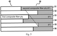
- Figure 5 shows an enlarged cross-sectional view of a leading or a trailing edge of a blade.
- the non-spanwise fiber plies 32, 34 are arranged between two adjacent spanwise fiber plies 31, 33, 35. This means the two adjacent spanwise fiber plies are spaced by one non-spanwise fiber ply. In the same manner, the two adjacent non-spanwise fiber plies are spaced by one spanwise fiber ply as well. For instance, first spanwise fiber ply 31 and second spanwise fiber ply 33 is spaced by first non-spanwise fiber ply 32.
- Figure 5 illustratively shows ends of the second composite fiber plies are staggered in chordwise direction of the blade ( Figure 4 also shows).
- ends of first spanwise fiber ply 31, first non-spanwise fiber ply 32, second spanwise fiber ply 33, second non-spanwise fiber ply 34, third spanwise fiber ply 35, and third non-spanwise fiber ply 36 are staggered so as to form interlock between the first composite fiber plies and the second composite fiber plies, thereby to prevent the plural adjacent second composite fiber plies (i.e. two or more than two adjacent second composite fiber plies) end at the same spot.
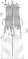
- Figure 6 illustratively shows ends of the second composite fiber plies are staggered in spanwise direction of the blade according to an embodiment of the invention.
- the second composite fiber plies 30 could be disposed at the leading edge or the trailing edge of the blade, and each of the second composite fiber plies is a part of one whole layer of blade.
- the first composite fiber ply and the second composite fiber ply are two separate pieces, but they are combined together to form one whole layer.
- first spanwise fiber ply 31 ends of first spanwise fiber ply 31, first non-spanwise fiber ply 32, second spanwise fiber ply 33, second non-spanwise fiber ply 34, third spanwise fiber ply 35, and third non-spanwise fiber ply 36 are also staggered so as to form interlock between the first composite fiber plies 40 and the second composite fiber plies 30, thereby to prevent the plural adjacent second composite fiber plies (i.e. two or more than two adjacent second composite fiber plies) end at the same spot.
- first spanwise fiber ply 31 being represented in solid line
- the other second composite fiber plies 32, 33, 34, 35, 36 are represented in broken lines such as dotted line and dot-dash line.
- the smallest rectangle area represents two second composite fiber plies 32, 35, wherein one is first non-spanwise fiber ply 32, and the other is third spanwise fiber ply 35 though first non-spanwise fiber ply 32 and third spanwise fiber ply 35 are overlapped in one area in Figure 6 .
- the second composite fiber plies end differently both in chordwise direction and in spanwise direction creating a staggered pattern.
- the interlock depends how the second composite fiber plies end.
- the interlock used herein actually is formed in a region where the material transition from one to another, for example, from all carbon to carbon and glass, and then to all glass. There will be a quick change in material properties in this region.
- the ends of the second composite fiber plies are designed to be staggered in chordwise direction and/or in spanwise direction of the blade which is beneficial to smooth such material transition. Thus, such interlock will stop the second composite fiber plies and/or the first composite fiber plies from delamination.
- Figure 7 shows the delamination of first composite fiber plies and second composite fiber plies when the load is applied on them.
- ends of all six second composite fiber plies are aligned, namely, they all end at the same or the substantially same spot, which will create a local strength weakness, leading to the disengagement of the first composite fiber plies and the second composite fiber plies while causing delamination between the plies of the first composite fiber plies and delamination between the plies of second composite fiber plies.
- Chordwise length used herein means the length size of second composite fiber ply or first composite fiber ply extending from leading edge 28 to trailing edge 29.
- Spanwise length used herein means the length size of second composite fiber ply or first composite fiber ply extending from root 21 to tip 22.
- chordwise length and spanwise length of spanwise fiber plies change regularly, that is, chordwise length and spanwise length of spanwise fiber plies decrease monotonically from first surface inwardly.
- chordwise length and spanwise length of first spanwise fiber ply 31 decrease successively (along the solid slash in Fig. 5 ) from surface toward interior.
- lengths of non-spanwise fiber plies do not decrease or increase monotonically from surface toward interior. Namely, neither chordwise length nor spanwise length of non-spanwise fiber plies decreases or increases monotonically from surface toward interior.
- Figure 8 is an enlarged and partial cross-sectional view of a leading or a trailing edge of a blade in another embodiment of the invention.
- blade comprises a plurality of first composite fiber plies and a plurality of second composite fiber plies.
- the first composite fiber plies and the second composite fiber plies are configured in the similar way as those shown in Fig. 5 .
- the chordwise length of first spanwise fiber ply 31, second spanwise fiber ply 33 and third spanwise fiber ply 35 decreases successively (along the solid slash).
- spanwise length of first spanwise fiber ply 31, second spanwise fiber ply 33 and third spanwise fiber ply 35 are also decreases successively from surface toward interior (not shown in Figures but similar to what is represented in Figure 6 ). While the chordwise length and spanwise length of non-spanwise fiber plies 32, 34 and 36 do not decrease or increase monotonically from surface toward interior either.
- Figures 9-11 show the orientation of fibers in the non-spanwise fiber plies and in the spanwise fiber plies when they are manufactured together.
- first spanwise fiber ply 31 has fibers 311 which are parallel to the spanwise direction of the blade (0° relative to the spanwise direction of the blade).
- the first non-spanwise fiber ply 32 adjacently disposed below the first spanwise fiber ply 31 has fibers 321 which are oriented at an angle of 45° relative to the spanwise direction of the blade (shown with the solid line).
- the first non-spanwise fiber ply can also has fibers 321 which are oriented at an angle of -45° relative to the spanwise direction of the blade (shown with the dashed line).
- the first non-spanwise fiber ply has fibers 321 which are oriented at an angle of 75° relative to the spanwise direction of the blade (shown with the solid line), or has fibers 321 are oriented at an angle of -75° relative to the spanwise direction of the blade (shown with the dashed line).
- Fig. 10 the first non-spanwise fiber ply has fibers 321 which are oriented at an angle of 75° relative to the spanwise direction of the blade (shown with the solid line), or has fibers 321 are oriented at an angle of -75° relative to the spanwise direction of the blade (shown with the dashed line).
- Fig. 10 the first non-spanwise fiber ply has fibers 321 which are oriented at an angle of 75° relative to the spanwise direction of
- the first non-spanwise fiber ply has fibers 321 which are oriented at an angle of 15° relative to the spanwise direction of the blade (shown with the solid line), or has fibers 321 are oriented at an angle of -15° relative to the spanwise direction of the blade (shown with the dashed line).
- the fibers woven in the first non-spanwise fiber ply can be oriented at an angle ranging from ⁇ 15° to ⁇ 75° relative to spanwise direction of the blade.
- the first non-spanwise fiber ply could have fibers oriented at angle of 45°
- the second non-spanwise fiber ply could have fibers oriented at angle of 15° (or 30°)
- the third non-spanwise fiber ply could have fibers oriented at angle of 75° (or 60°).
- the spanwise fiber plies takes the majority of load since they are oriented parallel to the spanwise direction of the blade. The external load comes from multiple directions. If the fibers of all the plies run in only one direction, it would be strong in that direction, but will actually result in strength weakness in the other directions.
- fibers 321 of the first non-spanwise fiber ply is just for illustration not for limitation.
- the fibers oriented at an angle between ⁇ 15° and ⁇ 75° can be applied to any other non-spanwise fiber plies, for instance, second or third non-spanwise fiber ply.
- first non-spanwise fiber ply 32 and the third spanwise fiber ply 35 end at the same spot or substantively end at a same spot.
- first non-spanwise fiber ply 32 and the third spanwise fiber ply 35 are separated by the second spanwise fiber ply 33 and the second non-spanwise fiber ply 34 (two plies), which avoid two adjacent fiber plies end at same spot, thereby reducing the possibility of forming local strength weakness.
- it also works when at least one ply is disposed between two adjacent second composite fiber plies ending at the same spot or at the substantively same spot.
- no more than two plies of a plurality of the second composite fiber plies end at a same spot or substantively end at a same spot.
- no more than two plies of a plurality of the second composite fiber plies end at a same spot or substantively end at a same spot both in chordwise direction and in spanwise direction.
- two plies substantively end at a same or substantially same spot means that the length (for example, the chordwise length or the spanwise length) of two plies 32, 35 differs within ⁇ 100 mil (the difference D ranges from -100 mil to 100 mil, i.e. -2,54 mm to 2,54 mm) .
- no more than two plies 32, 35 of a plurality of the second composite fiber plies end at the substantively same spot differ (the difference D) within 20 times of an average thickness of one ply of the second composite fiber plies.
- chordwise length L1 of each of a plurality of the first composite fiber plies 40 accounts for 50% to 99% of the whole chordwise length of the blade
- chordwise length L2 of each of a plurality of the second composite fiber plies 30 accounts for 1% to 50% of the whole chordwise length of the blade.
- Chordwise length used herein means the length size of second composite fiber ply or first composite fiber ply extending from leading edge to trailing edge.
- Edge thickness of the blade is made up of entirely second composite fiber plies (i.e. glass fiber plies) accounting for 1% to 50% of the whole chordwise length of the blade.
- the blade thickness tapers in the manner of being thicker in the middle of the blade to being thinner on the edge of the blade.
- the number of second composite fiber plies used drives the amount of chordwise length where the part is entirely second composite fiber material such as glass. More second composite fiber plies make trailing or leading edge of blade withstand higher strain during a bird impact since the reinforcement fiber material such as glass has higher strain to failure to provide an improved bird-strike capability.
- the second composite fiber plies 30 wrap around trailing edge 29 (shown in Fig. 2 ) to cover the trailing edge.
- the second composite fiber plies 30 can have same or similar structure as shown in Fig 3 , 4 and 5 .
- Figures 12, 13 and 14 are illustrative cross-sectional views of blade in different embodiments of the invention.
- the second composite fiber plies 30 are disposed at the trailing edge 29 of blade which wrap around the trailing edge.
- the second composite fiber plies 30 are disposed at the leading edge 28 of blade which wrap around the leading edge.
- the second composite fiber plies 30 are disposed at both the leading edge 28 and trailing edge 29 of blade which wrap around both two edges.
- the second composite fiber plies i.e. glass fiber
- the stiffness of the blade will decrease if the reinforcement glass fiber plies are laid up more while composite carbon fiber layers are laid up less. So, it is not suggested to dispose the reinforcement glass fiber plies throughout the surfaces of the blade.
- Figure 15 shows the process of a method of making a blade according to an embodiment of the invention.
- the first composite fiber ply and the second composite fiber ply are two separate pieces, but they are combined together to form one whole layer.
- Each whole layer of the blade including the first composite fiber ply and the second composite fiber ply is laid down before laying the next whole layer, and repeating step 110 to step 130 until the desired layers are obtained on the blade 140.
- ends of the second composite fiber plies be staggered (for example, be staggered in both chordwise direction and spanwise direction of the blade) such that interlock between the first composite fiber plies and the second composite fiber plies is formed at a region where the second composite fiber plies end and meet with the first composite fiber plies.
- Figure 16 shows the process of a method of making a blade according to another embodiment of the invention.
- Step 110 and step 120 shown in Fig. 15 could be reversed in a contrary sequence in Fig. 16 .
- a subsequent whole layer i.e. a second whole layer
- the previous whole layer of blade i.e. the first whole layer
- the blade 20 could be constructed from one side of the blade toward the other side of the blade, or from two sides of the blade simultaneously.
- the first composite fiber plies and the second composite fiber plies are combined together via any conventional techniques known in the art such as autoclave cure, press cure, resin transfer molding (RTM), vacuum assisted resin transfer molding (VARTM) and so on. It could be understood that the expression of “combine”, “combined” and/or “combination” used herein intends to mean first composite fiber plies and second composite fiber plies meet with each other rather than being physically joined together when they are laid down together on the blade.
- first composite fiber plies and second composite fiber plies may vary depend on the actual requirements of the blade.
- Blade represented in the above-mentioned embodiments as well as defined in the claims appended as follows may be incorporated in an engine of an aircraft (i.e. GE9X from General Electric Company).
- the second composite fiber plies according the present application could be applied in turbine blade as well. That is, the second composite fiber plies are disposed at the leading edge and/or trailing edge of the turbine blade.
- the carbon composite fibers have high stiffness and high strength.
- Some blades use the carbon composite fibers be designed in a way that run all the way to the trailing edge and/or leading edge.
- the carbon composite fibers have lower strain to failure compared to glass fibers.
- the present disclosure adopts reinforcement fiber materials such as glass fibers, and reinforcement structure such as the interlock generated transition area in by the staggered ends of the second composite fiber plies in both chordwise direction and spanwise direction of the blade.
- the glass fibers have a higher strain to failure resulting in an improved birdstrike capability compared to the carbon composite fibers.
- chordwise length and spanwise length of reinforcement spanwise glass plies monotonically tapers from the surface inwardly.
- the chordwise length and spanwise length of reinforcement non-spanwise glass plies do not monotonically increase or monotonically decrease from the surface inwardly. This provides a smooth and robust transition from all carbon to carbon and glass then to all glass.
- the blade of the present disclosure has the following advantages of 1) having a higher strain to failure at the trailing edge and/or leading edge; 2) allowing the blade to be designed with a reduced thickness and larger chord; and 3) making the machines like engine or aircraft incorporating such engine in a good performance and high efficiency.
Landscapes
- Engineering & Computer Science (AREA)
- Mechanical Engineering (AREA)
- Chemical & Material Sciences (AREA)
- Composite Materials (AREA)
- General Engineering & Computer Science (AREA)
- Materials Engineering (AREA)
- Architecture (AREA)
- Turbine Rotor Nozzle Sealing (AREA)
- Moulding By Coating Moulds (AREA)
- Laminated Bodies (AREA)
Claims (13)
- Aube (20) destinée à un moteur d'avion, comprenant :une pluralité de premières couches de fibres composites (40) ; etune pluralité de secondes couches de fibres composites (30) ;les extrémités des secondes couches de fibres (30) étant décalées de telle sorte que l'emboîtement entre les premières couches de fibres composites (40) et les secondes couches de fibres composites (30) est formé dans une région où les secondes couches de fibres composites (30) se terminent et se rejoignent avec les premières couches de fibres composites (40) ; caractérisé en ce quela pluralité des secondes couches de fibres composites (30) comprend des couches de fibres dans le sens de l'envergure (31, 33, 35 37) diminuant à la fois en longueur dans le sens de la corde et en longueur dans le sens de l'envergure de manière monotone à partir de la surface de l'aube vers l'intérieur et des couches de fibres qui ne vont pas dans le sens de l'envergure (32, 34, 36, 38) diminuant ou augmentant de manière non monotone à la fois en longueur dans le sens de la corde et en longueur dans le sens de l'envergure à partir de la surface de l'aube vers l'intérieur, dans laquelle les couches de fibres dans le sens de l'envergure ont des fibres disposées dans une direction suivant l'envergure, et dans laquelle les couches de fibres qui ne vont pas dans le sens de l'envergure ont des fibres disposées à un angle par rapport à la direction suivant l'envergure.
- Aube selon la revendication 1, dans laquelle les secondes couches de fibres composites (30) comprennent des fibres unidirectionnelles (311, 321).
- Aube selon l'une quelconque des revendications précédentes, dans laquelle les couches de fibres qui ne vont pas dans le sens de l'envergure (32, 34, 36) sont disposées entre des couches de fibres dans le sens de l'envergure (31, 33, 35 37) adjacentes de telle sorte que les couches de fibres dans le sens de l'envergure (31, 33, 35, 37) adjacentes sont espacées par les couches de fibres qui ne vont pas dans le sens de l'envergure (32, 34, 36).
- Aube selon la revendication 1 ou 3, dans laquelle les couches de fibres qui ne vont pas dans le sens de l'envergure (32, 34, 36, 38) ont des fibres (321) orientées à un angle compris entre 15 ° et 75 ° et/ou ont des fibres (321) orientées à un angle compris entre - 75 ° et -15 ° par rapport à une direction suivant l'envergure de l'aube.
- Aube selon l'une quelconque des revendications précédentes, dans laquelle pas plus de deux couches (32, 35) d'une pluralité des secondes couches de fibres composites (30) se terminent au même endroit ou sensiblement au même endroit.
- Aube selon la revendication 5, dans laquelle pas plus de deux couches (32, 35) d'une pluralité des secondes couches de fibres composites (30) se terminant sensiblement au même endroit diffèrent à moins de 2,54 mm (100 mil), ou pas plus de deux couches (32, 35) d'une pluralité de secondes couches de fibres composites (30) se terminant sensiblement au même endroit diffèrent de 20 fois d'une épaisseur moyenne d'une couche des secondes couches de fibres composites (30).
- Aube selon l'une quelconque des revendications 5 ou 6, dans laquelle au moins une couche est disposée entre les secondes couches de fibres composites adjacentes se terminant au même endroit ou sensiblement au même endroit.
- Aube selon l'une quelconque des revendications précédentes, dans laquelle la longueur dans le sens de la corde de chacune d'une pluralité des premières couches de fibres composites représente 50 % à 99 % de la longueur totale dans le sens de la corde de l'aube et la longueur dans le sens de la corde de chacune d'une pluralité des secondes couches de fibres composites représente 1 % à 50 % de toute la longueur dans le sens de la corde de l'aube.
- Aube selon l'une quelconque des revendications précédentes, dans laquelle une pluralité des premières couches de fibres composites ne s'étendent pas jusqu'à une extrémité d'un bord d'attaque et/ou une extrémité d'un bord de fuite de l'aube.
- Aube selon la revendication 9, dans laquelle l'épaisseur du bord de l'aube est constituée entièrement de secondes couches de fibres composites représentant 1 % à 50 % de la longueur totale dans le sens de la corde de l'aube.
- Aube selon l'une quelconque des revendications précédentes, dans laquelle les secondes couches de fibres composites sont disposées sur un bord de fuite et/ou un bord d'attaque de l'aube.
- Moteur d'un aéronef comprenant l'une quelconque des aubes (20) des revendications 1 à 11.
- Procédé de fabrication d'une aube comprenant :la pose d'une pluralité de premières couches de fibres composites sur l'aube (110) ; etla pose d'une pluralité de secondes couches de fibres composites (120) en combinaison avec la pluralité des premières couches de fibres composites (130) pour que les extrémités des secondes couches de fibres composites soient décalées de telle sorte que l'emboîtement entre les premières couches de fibres composites et les secondes couches de fibres composites est formé dans une région où les secondes couches de fibres composites se terminent et rejoignent les premières couches de fibres composites ; et caractérisé en ce quela pluralité des secondes couches de fibres composites (30) comprend des couches de fibres dans le sens de l'envergure (31, 33, 35, 37) diminuant à la fois en longueur dans le sens de la corde et en longueur dans le sens de l'envergure de manière monotone à partir de la surface de l'aube vers l'intérieur et des couches de fibres qui ne vont pas dans le sens de l'envergure (32, 34, 36, 38) diminuant ou augmentant de manière non monotone à la fois en longueur dans le sens de la corde et en longueur dans le sens de l'envergure à partir de la surface de l'aube vers l'intérieur, dans lequel les couches de fibres dans le sens de l'envergure ont des fibres disposées dans une direction suivant l'envergure, et dans lequel les couches de fibres qui ne vont pas dans le sens de l'envergure ont des fibres disposées à un angle par rapport à la direction suivant l'envergure.
Applications Claiming Priority (1)
| Application Number | Priority Date | Filing Date | Title |
|---|---|---|---|
| US15/882,044 US11931981B2 (en) | 2018-01-29 | 2018-01-29 | Reinforced composite blade and method of making a blade |
Publications (2)
| Publication Number | Publication Date |
|---|---|
| EP3517732A1 EP3517732A1 (fr) | 2019-07-31 |
| EP3517732B1 true EP3517732B1 (fr) | 2022-03-23 |
Family
ID=65236909
Family Applications (1)
| Application Number | Title | Priority Date | Filing Date |
|---|---|---|---|
| EP19153804.0A Active EP3517732B1 (fr) | 2018-01-29 | 2019-01-25 | Aube composite renforcé et procédé de fabrication d'une aube |
Country Status (5)
| Country | Link |
|---|---|
| US (1) | US11931981B2 (fr) |
| EP (1) | EP3517732B1 (fr) |
| JP (1) | JP2019173746A (fr) |
| CN (1) | CN110094237B (fr) |
| CA (1) | CA3030334A1 (fr) |
Families Citing this family (13)
| Publication number | Priority date | Publication date | Assignee | Title |
|---|---|---|---|---|
| FR3087701B1 (fr) * | 2018-10-30 | 2021-11-26 | Safran Aircraft Engines | Hybridation des fibres du renfort fibreux d'une aube de soufflante |
| FR3108666B1 (fr) * | 2020-03-27 | 2022-04-01 | Safran Aircraft Engines | Texture fibreuse pour aube de turbomachine en matériau composite |
| FR3111658B1 (fr) * | 2020-06-18 | 2022-07-15 | Safran Aircraft Engines | Aube en matériau composite à renfort fibreux tissé tridimensionnel et peau tissée bidimensionnel et son procédé de fabrication |
| CN114961873B (zh) * | 2021-02-25 | 2024-05-31 | 中国航发商用航空发动机有限责任公司 | 可恢复变形的叶片及包含其的涡扇发动机 |
| CN113147053B (zh) * | 2021-05-21 | 2023-01-24 | 江苏恒神股份有限公司 | 加筋结构件端框及其成型方法 |
| US11927113B2 (en) * | 2021-08-06 | 2024-03-12 | Rtx Corporation | Composite fan blade airfoil, methods of manufacture thereof and articles comprising the same |
| WO2024006078A1 (fr) * | 2022-06-27 | 2024-01-04 | Helicoid Industries Inc. | Fibre renforcée résistante aux chocs importants pour la protection de bord d'attaque de structures aérodynamiques |
| US12503980B2 (en) | 2022-11-01 | 2025-12-23 | General Electric Company | Gas turbine engine |
| US12326155B2 (en) | 2023-02-20 | 2025-06-10 | General Electric Company | Turbine engine with composite airfoils |
| US12320273B2 (en) * | 2023-02-20 | 2025-06-03 | General Electric Company | Turbine engine with composite airfoils |
| WO2025109815A1 (fr) * | 2023-11-21 | 2025-05-30 | 株式会社Ihi | Lame en matériau composite |
| US20250361658A1 (en) * | 2024-05-24 | 2025-11-27 | General Electric Company | Three-dimensional woven fabric for a composite component |
| CN119860316B (zh) * | 2024-12-31 | 2025-10-17 | 中国华能集团清洁能源技术研究院有限公司 | 风机叶片和风机 |
Family Cites Families (27)
| Publication number | Priority date | Publication date | Assignee | Title |
|---|---|---|---|---|
| US4051289A (en) * | 1976-04-12 | 1977-09-27 | General Electric Company | Composite airfoil construction |
| CA2070522A1 (fr) | 1991-07-22 | 1993-01-23 | Jan C. Schilling | Aubes/pales composites pour soufflante |
| US5375978A (en) * | 1992-05-01 | 1994-12-27 | General Electric Company | Foreign object damage resistant composite blade and manufacture |
| US5876651A (en) | 1996-05-29 | 1999-03-02 | United Technologies Corporation | Method for forming a composite structure |
| US7575417B2 (en) * | 2003-09-05 | 2009-08-18 | General Electric Company | Reinforced fan blade |
| US7510379B2 (en) * | 2005-12-22 | 2009-03-31 | General Electric Company | Composite blading member and method for making |
| JP4699255B2 (ja) * | 2006-03-24 | 2011-06-08 | 三菱重工業株式会社 | 風車翼 |
| AT503290B1 (de) * | 2006-06-23 | 2007-09-15 | Fischer Adv Components Gmbh | Führungsträger für triebwerksverkleidungen |
| DE102006049818A1 (de) | 2006-10-18 | 2008-04-24 | Rolls-Royce Deutschland Ltd & Co Kg | Fanschaufel aus Textilverbundwerkstoff |
| US8475895B2 (en) * | 2006-11-21 | 2013-07-02 | General Electric Company | Articles comprising composite structures having mounting flanges |
| US20090165924A1 (en) * | 2006-11-28 | 2009-07-02 | General Electric Company | Method of manufacturing cmc articles having small complex features |
| CN102308083B (zh) | 2008-12-05 | 2016-04-13 | 模组风能公司 | 高效风轮机叶片 |
| DE102009009272B4 (de) * | 2009-02-17 | 2013-02-28 | Siemens Aktiengesellschaft | Qualitätsprüfung für Rotorblätter einer Windenergieanlage |
| GB0908707D0 (en) | 2009-05-21 | 2009-07-01 | Rolls Royce Plc | Reinforced composite aerofoil blade |
| EP2594805B1 (fr) * | 2010-07-15 | 2019-05-01 | IHI Corporation | Pale de rotor de soufflante et soufflante |
| US20130064676A1 (en) | 2011-09-13 | 2013-03-14 | United Technologies Corporation | Composite filled metal airfoil |
| US20130330496A1 (en) * | 2012-06-06 | 2013-12-12 | General Electric Company | Composite structure with low density core and composite stitching reinforcement |
| EP2971558A1 (fr) | 2013-03-13 | 2016-01-20 | Rolls-Royce Corporation | Composant composite conforme et procédé de fabrication |
| EP2781734B1 (fr) | 2013-03-20 | 2019-02-20 | Siemens Aktiengesellschaft | Pale de rotor avec une structure de support segmentée et procédé de fabrication de ladite pale |
| US20160250812A1 (en) | 2013-10-14 | 2016-09-01 | United Technologies Corporation | Automated laminate composite solid ply generation |
| US20150240659A1 (en) | 2014-02-24 | 2015-08-27 | U.S. Army Research Laboratory Attn: Rdrl-Loc-I | Airfoil or rotor blade having a continuous trailing edge flap |
| WO2015155446A1 (fr) * | 2014-04-07 | 2015-10-15 | Snecma | Verrou de rotor de turbomachine |
| US20160032939A1 (en) | 2014-07-31 | 2016-02-04 | General Electric Company | Airfoil structures |
| GB201507281D0 (en) | 2015-04-29 | 2015-06-10 | Composite Technology & Applic Ltd | Methods and systems for bonding |
| US9976429B2 (en) | 2015-06-09 | 2018-05-22 | General Electric Company | Composite disk |
| US10450870B2 (en) | 2016-02-09 | 2019-10-22 | General Electric Company | Frangible gas turbine engine airfoil |
| US10590945B2 (en) * | 2016-08-10 | 2020-03-17 | United Technologies Corporation | Fiber composite material and preform and fan blade made therefrom |
-
2018
- 2018-01-29 US US15/882,044 patent/US11931981B2/en active Active
-
2019
- 2019-01-17 CA CA3030334A patent/CA3030334A1/fr not_active Abandoned
- 2019-01-25 EP EP19153804.0A patent/EP3517732B1/fr active Active
- 2019-01-28 JP JP2019011926A patent/JP2019173746A/ja active Pending
- 2019-01-29 CN CN201910085604.3A patent/CN110094237B/zh active Active
Non-Patent Citations (1)
| Title |
|---|
| None * |
Also Published As
| Publication number | Publication date |
|---|---|
| US11931981B2 (en) | 2024-03-19 |
| CN110094237A (zh) | 2019-08-06 |
| CN110094237B (zh) | 2022-07-15 |
| JP2019173746A (ja) | 2019-10-10 |
| US20190234420A1 (en) | 2019-08-01 |
| CA3030334A1 (fr) | 2019-07-29 |
| EP3517732A1 (fr) | 2019-07-31 |
Similar Documents
| Publication | Publication Date | Title |
|---|---|---|
| EP3517732B1 (fr) | Aube composite renforcé et procédé de fabrication d'une aube | |
| US8647070B2 (en) | Reinforced composite aerofoil blade | |
| CN109098929B (zh) | 具有混合式翼梁帽的风力涡轮叶片及制造的相关联方法 | |
| US20130064676A1 (en) | Composite filled metal airfoil | |
| EP2096269B1 (fr) | Ensemble d'enlignement de revêtements de soufflante pour moteur à turbine à gaz | |
| US7780420B1 (en) | Turbine blade with a foam metal leading or trailing edge | |
| US8715809B2 (en) | Composite structure | |
| EP3561232B1 (fr) | Composant composite | |
| CN103183128B (zh) | 内部护罩、具有内部护罩的飞行器以及相关方法 | |
| US20110229334A1 (en) | Composite leading edge sheath and dovetail root undercut | |
| US20150204200A1 (en) | Fibre composite component for the rotor blade of a wind turbine | |
| US9878501B2 (en) | Method of manufacturing a frangible blade | |
| US20140086751A1 (en) | Annulus filler for axial flow machine | |
| US9243512B1 (en) | Rotary machine with a frangible composite blade | |
| JP2012086564A (ja) | 複合材料部品及びその製造方法 | |
| US10865649B2 (en) | Gas turbine engine | |
| GB2406145A (en) | Reinforced composite blade | |
| US20180274374A1 (en) | Blade comprising a leading edge shield and method for producing the blade | |
| WO2014139534A1 (fr) | Pales d'éolienne dotées de longerons en couches, à plusieurs composants, et systèmes et procédés associés | |
| CN105008670A (zh) | 包括多个插入件区段的混合涡轮叶片 | |
| US9828862B2 (en) | Frangible airfoil | |
| WO2016115352A1 (fr) | Profil aérodynamique composite cassant | |
| US12565843B2 (en) | Composite blade | |
| CN116412060B (zh) | 叶片的腹板及叶片 | |
| GB2569455A (en) | Gas turbine engine |
Legal Events
| Date | Code | Title | Description |
|---|---|---|---|
| PUAI | Public reference made under article 153(3) epc to a published international application that has entered the european phase |
Free format text: ORIGINAL CODE: 0009012 |
|
| STAA | Information on the status of an ep patent application or granted ep patent |
Free format text: STATUS: THE APPLICATION HAS BEEN PUBLISHED |
|
| AK | Designated contracting states |
Kind code of ref document: A1 Designated state(s): AL AT BE BG CH CY CZ DE DK EE ES FI FR GB GR HR HU IE IS IT LI LT LU LV MC MK MT NL NO PL PT RO RS SE SI SK SM TR |
|
| AX | Request for extension of the european patent |
Extension state: BA ME |
|
| STAA | Information on the status of an ep patent application or granted ep patent |
Free format text: STATUS: REQUEST FOR EXAMINATION WAS MADE |
|
| 17P | Request for examination filed |
Effective date: 20200131 |
|
| RBV | Designated contracting states (corrected) |
Designated state(s): AL AT BE BG CH CY CZ DE DK EE ES FI FR GB GR HR HU IE IS IT LI LT LU LV MC MK MT NL NO PL PT RO RS SE SI SK SM TR |
|
| STAA | Information on the status of an ep patent application or granted ep patent |
Free format text: STATUS: EXAMINATION IS IN PROGRESS |
|
| 17Q | First examination report despatched |
Effective date: 20200527 |
|
| GRAP | Despatch of communication of intention to grant a patent |
Free format text: ORIGINAL CODE: EPIDOSNIGR1 |
|
| STAA | Information on the status of an ep patent application or granted ep patent |
Free format text: STATUS: GRANT OF PATENT IS INTENDED |
|
| INTG | Intention to grant announced |
Effective date: 20210510 |
|
| GRAJ | Information related to disapproval of communication of intention to grant by the applicant or resumption of examination proceedings by the epo deleted |
Free format text: ORIGINAL CODE: EPIDOSDIGR1 |
|
| STAA | Information on the status of an ep patent application or granted ep patent |
Free format text: STATUS: EXAMINATION IS IN PROGRESS |
|
| INTC | Intention to grant announced (deleted) | ||
| GRAP | Despatch of communication of intention to grant a patent |
Free format text: ORIGINAL CODE: EPIDOSNIGR1 |
|
| STAA | Information on the status of an ep patent application or granted ep patent |
Free format text: STATUS: GRANT OF PATENT IS INTENDED |
|
| INTG | Intention to grant announced |
Effective date: 20211019 |
|
| GRAS | Grant fee paid |
Free format text: ORIGINAL CODE: EPIDOSNIGR3 |
|
| GRAA | (expected) grant |
Free format text: ORIGINAL CODE: 0009210 |
|
| STAA | Information on the status of an ep patent application or granted ep patent |
Free format text: STATUS: THE PATENT HAS BEEN GRANTED |
|
| AK | Designated contracting states |
Kind code of ref document: B1 Designated state(s): AL AT BE BG CH CY CZ DE DK EE ES FI FR GB GR HR HU IE IS IT LI LT LU LV MC MK MT NL NO PL PT RO RS SE SI SK SM TR |
|
| REG | Reference to a national code |
Ref country code: GB Ref legal event code: FG4D |
|
| REG | Reference to a national code |
Ref country code: CH Ref legal event code: EP |
|
| REG | Reference to a national code |
Ref country code: IE Ref legal event code: FG4D |
|
| REG | Reference to a national code |
Ref country code: DE Ref legal event code: R096 Ref document number: 602019012701 Country of ref document: DE |
|
| REG | Reference to a national code |
Ref country code: AT Ref legal event code: REF Ref document number: 1477558 Country of ref document: AT Kind code of ref document: T Effective date: 20220415 |
|
| REG | Reference to a national code |
Ref country code: LT Ref legal event code: MG9D |
|
| REG | Reference to a national code |
Ref country code: NL Ref legal event code: MP Effective date: 20220323 |
|
| PG25 | Lapsed in a contracting state [announced via postgrant information from national office to epo] |
Ref country code: SE Free format text: LAPSE BECAUSE OF FAILURE TO SUBMIT A TRANSLATION OF THE DESCRIPTION OR TO PAY THE FEE WITHIN THE PRESCRIBED TIME-LIMIT Effective date: 20220323 Ref country code: RS Free format text: LAPSE BECAUSE OF FAILURE TO SUBMIT A TRANSLATION OF THE DESCRIPTION OR TO PAY THE FEE WITHIN THE PRESCRIBED TIME-LIMIT Effective date: 20220323 Ref country code: NO Free format text: LAPSE BECAUSE OF FAILURE TO SUBMIT A TRANSLATION OF THE DESCRIPTION OR TO PAY THE FEE WITHIN THE PRESCRIBED TIME-LIMIT Effective date: 20220623 Ref country code: LT Free format text: LAPSE BECAUSE OF FAILURE TO SUBMIT A TRANSLATION OF THE DESCRIPTION OR TO PAY THE FEE WITHIN THE PRESCRIBED TIME-LIMIT Effective date: 20220323 Ref country code: HR Free format text: LAPSE BECAUSE OF FAILURE TO SUBMIT A TRANSLATION OF THE DESCRIPTION OR TO PAY THE FEE WITHIN THE PRESCRIBED TIME-LIMIT Effective date: 20220323 Ref country code: BG Free format text: LAPSE BECAUSE OF FAILURE TO SUBMIT A TRANSLATION OF THE DESCRIPTION OR TO PAY THE FEE WITHIN THE PRESCRIBED TIME-LIMIT Effective date: 20220623 |
|
| REG | Reference to a national code |
Ref country code: AT Ref legal event code: MK05 Ref document number: 1477558 Country of ref document: AT Kind code of ref document: T Effective date: 20220323 |
|
| PG25 | Lapsed in a contracting state [announced via postgrant information from national office to epo] |
Ref country code: LV Free format text: LAPSE BECAUSE OF FAILURE TO SUBMIT A TRANSLATION OF THE DESCRIPTION OR TO PAY THE FEE WITHIN THE PRESCRIBED TIME-LIMIT Effective date: 20220323 Ref country code: GR Free format text: LAPSE BECAUSE OF FAILURE TO SUBMIT A TRANSLATION OF THE DESCRIPTION OR TO PAY THE FEE WITHIN THE PRESCRIBED TIME-LIMIT Effective date: 20220624 Ref country code: FI Free format text: LAPSE BECAUSE OF FAILURE TO SUBMIT A TRANSLATION OF THE DESCRIPTION OR TO PAY THE FEE WITHIN THE PRESCRIBED TIME-LIMIT Effective date: 20220323 |
|
| PG25 | Lapsed in a contracting state [announced via postgrant information from national office to epo] |
Ref country code: NL Free format text: LAPSE BECAUSE OF FAILURE TO SUBMIT A TRANSLATION OF THE DESCRIPTION OR TO PAY THE FEE WITHIN THE PRESCRIBED TIME-LIMIT Effective date: 20220323 |
|
| PG25 | Lapsed in a contracting state [announced via postgrant information from national office to epo] |
Ref country code: SM Free format text: LAPSE BECAUSE OF FAILURE TO SUBMIT A TRANSLATION OF THE DESCRIPTION OR TO PAY THE FEE WITHIN THE PRESCRIBED TIME-LIMIT Effective date: 20220323 Ref country code: SK Free format text: LAPSE BECAUSE OF FAILURE TO SUBMIT A TRANSLATION OF THE DESCRIPTION OR TO PAY THE FEE WITHIN THE PRESCRIBED TIME-LIMIT Effective date: 20220323 Ref country code: RO Free format text: LAPSE BECAUSE OF FAILURE TO SUBMIT A TRANSLATION OF THE DESCRIPTION OR TO PAY THE FEE WITHIN THE PRESCRIBED TIME-LIMIT Effective date: 20220323 Ref country code: PT Free format text: LAPSE BECAUSE OF FAILURE TO SUBMIT A TRANSLATION OF THE DESCRIPTION OR TO PAY THE FEE WITHIN THE PRESCRIBED TIME-LIMIT Effective date: 20220725 Ref country code: ES Free format text: LAPSE BECAUSE OF FAILURE TO SUBMIT A TRANSLATION OF THE DESCRIPTION OR TO PAY THE FEE WITHIN THE PRESCRIBED TIME-LIMIT Effective date: 20220323 Ref country code: EE Free format text: LAPSE BECAUSE OF FAILURE TO SUBMIT A TRANSLATION OF THE DESCRIPTION OR TO PAY THE FEE WITHIN THE PRESCRIBED TIME-LIMIT Effective date: 20220323 Ref country code: CZ Free format text: LAPSE BECAUSE OF FAILURE TO SUBMIT A TRANSLATION OF THE DESCRIPTION OR TO PAY THE FEE WITHIN THE PRESCRIBED TIME-LIMIT Effective date: 20220323 Ref country code: AT Free format text: LAPSE BECAUSE OF FAILURE TO SUBMIT A TRANSLATION OF THE DESCRIPTION OR TO PAY THE FEE WITHIN THE PRESCRIBED TIME-LIMIT Effective date: 20220323 |
|
| PG25 | Lapsed in a contracting state [announced via postgrant information from national office to epo] |
Ref country code: PL Free format text: LAPSE BECAUSE OF FAILURE TO SUBMIT A TRANSLATION OF THE DESCRIPTION OR TO PAY THE FEE WITHIN THE PRESCRIBED TIME-LIMIT Effective date: 20220323 Ref country code: IS Free format text: LAPSE BECAUSE OF FAILURE TO SUBMIT A TRANSLATION OF THE DESCRIPTION OR TO PAY THE FEE WITHIN THE PRESCRIBED TIME-LIMIT Effective date: 20220723 Ref country code: AL Free format text: LAPSE BECAUSE OF FAILURE TO SUBMIT A TRANSLATION OF THE DESCRIPTION OR TO PAY THE FEE WITHIN THE PRESCRIBED TIME-LIMIT Effective date: 20220323 |
|
| REG | Reference to a national code |
Ref country code: DE Ref legal event code: R097 Ref document number: 602019012701 Country of ref document: DE |
|
| PLBE | No opposition filed within time limit |
Free format text: ORIGINAL CODE: 0009261 |
|
| STAA | Information on the status of an ep patent application or granted ep patent |
Free format text: STATUS: NO OPPOSITION FILED WITHIN TIME LIMIT |
|
| PG25 | Lapsed in a contracting state [announced via postgrant information from national office to epo] |
Ref country code: DK Free format text: LAPSE BECAUSE OF FAILURE TO SUBMIT A TRANSLATION OF THE DESCRIPTION OR TO PAY THE FEE WITHIN THE PRESCRIBED TIME-LIMIT Effective date: 20220323 |
|
| 26N | No opposition filed |
Effective date: 20230102 |
|
| PG25 | Lapsed in a contracting state [announced via postgrant information from national office to epo] |
Ref country code: SI Free format text: LAPSE BECAUSE OF FAILURE TO SUBMIT A TRANSLATION OF THE DESCRIPTION OR TO PAY THE FEE WITHIN THE PRESCRIBED TIME-LIMIT Effective date: 20220323 |
|
| P01 | Opt-out of the competence of the unified patent court (upc) registered |
Effective date: 20230411 |
|
| PG25 | Lapsed in a contracting state [announced via postgrant information from national office to epo] |
Ref country code: IT Free format text: LAPSE BECAUSE OF FAILURE TO SUBMIT A TRANSLATION OF THE DESCRIPTION OR TO PAY THE FEE WITHIN THE PRESCRIBED TIME-LIMIT Effective date: 20220323 |
|
| REG | Reference to a national code |
Ref country code: CH Ref legal event code: PL |
|
| PG25 | Lapsed in a contracting state [announced via postgrant information from national office to epo] |
Ref country code: LU Free format text: LAPSE BECAUSE OF NON-PAYMENT OF DUE FEES Effective date: 20230125 |
|
| REG | Reference to a national code |
Ref country code: BE Ref legal event code: MM Effective date: 20230131 |
|
| PG25 | Lapsed in a contracting state [announced via postgrant information from national office to epo] |
Ref country code: LI Free format text: LAPSE BECAUSE OF NON-PAYMENT OF DUE FEES Effective date: 20230131 Ref country code: CH Free format text: LAPSE BECAUSE OF NON-PAYMENT OF DUE FEES Effective date: 20230131 |
|
| PG25 | Lapsed in a contracting state [announced via postgrant information from national office to epo] |
Ref country code: BE Free format text: LAPSE BECAUSE OF NON-PAYMENT OF DUE FEES Effective date: 20230131 |
|
| PG25 | Lapsed in a contracting state [announced via postgrant information from national office to epo] |
Ref country code: IE Free format text: LAPSE BECAUSE OF NON-PAYMENT OF DUE FEES Effective date: 20230125 |
|
| PG25 | Lapsed in a contracting state [announced via postgrant information from national office to epo] |
Ref country code: MC Free format text: LAPSE BECAUSE OF FAILURE TO SUBMIT A TRANSLATION OF THE DESCRIPTION OR TO PAY THE FEE WITHIN THE PRESCRIBED TIME-LIMIT Effective date: 20220323 |
|
| PG25 | Lapsed in a contracting state [announced via postgrant information from national office to epo] |
Ref country code: MC Free format text: LAPSE BECAUSE OF FAILURE TO SUBMIT A TRANSLATION OF THE DESCRIPTION OR TO PAY THE FEE WITHIN THE PRESCRIBED TIME-LIMIT Effective date: 20220323 |
|
| PG25 | Lapsed in a contracting state [announced via postgrant information from national office to epo] |
Ref country code: CY Free format text: LAPSE BECAUSE OF FAILURE TO SUBMIT A TRANSLATION OF THE DESCRIPTION OR TO PAY THE FEE WITHIN THE PRESCRIBED TIME-LIMIT; INVALID AB INITIO Effective date: 20190125 |
|
| PG25 | Lapsed in a contracting state [announced via postgrant information from national office to epo] |
Ref country code: HU Free format text: LAPSE BECAUSE OF FAILURE TO SUBMIT A TRANSLATION OF THE DESCRIPTION OR TO PAY THE FEE WITHIN THE PRESCRIBED TIME-LIMIT; INVALID AB INITIO Effective date: 20190125 |
|
| PG25 | Lapsed in a contracting state [announced via postgrant information from national office to epo] |
Ref country code: TR Free format text: LAPSE BECAUSE OF FAILURE TO SUBMIT A TRANSLATION OF THE DESCRIPTION OR TO PAY THE FEE WITHIN THE PRESCRIBED TIME-LIMIT Effective date: 20220323 |
|
| PGFP | Annual fee paid to national office [announced via postgrant information from national office to epo] |
Ref country code: GB Payment date: 20251219 Year of fee payment: 8 |
|
| PGFP | Annual fee paid to national office [announced via postgrant information from national office to epo] |
Ref country code: FR Payment date: 20251217 Year of fee payment: 8 |
|
| PGFP | Annual fee paid to national office [announced via postgrant information from national office to epo] |
Ref country code: DE Payment date: 20251217 Year of fee payment: 8 |