EP3517817B1 - Unabhängig hydraulisch eingespannte und abgedichtete armatur - Google Patents
Unabhängig hydraulisch eingespannte und abgedichtete armatur Download PDFInfo
- Publication number
- EP3517817B1 EP3517817B1 EP19151984.2A EP19151984A EP3517817B1 EP 3517817 B1 EP3517817 B1 EP 3517817B1 EP 19151984 A EP19151984 A EP 19151984A EP 3517817 B1 EP3517817 B1 EP 3517817B1
- Authority
- EP
- European Patent Office
- Prior art keywords
- annular
- seal
- annular piston
- grip
- pipe
- Prior art date
- Legal status (The legal status is an assumption and is not a legal conclusion. Google has not performed a legal analysis and makes no representation as to the accuracy of the status listed.)
- Active
Links
Images
Classifications
-
- F—MECHANICAL ENGINEERING; LIGHTING; HEATING; WEAPONS; BLASTING
- F16—ENGINEERING ELEMENTS AND UNITS; GENERAL MEASURES FOR PRODUCING AND MAINTAINING EFFECTIVE FUNCTIONING OF MACHINES OR INSTALLATIONS; THERMAL INSULATION IN GENERAL
- F16L—PIPES; JOINTS OR FITTINGS FOR PIPES; SUPPORTS FOR PIPES, CABLES OR PROTECTIVE TUBING; MEANS FOR THERMAL INSULATION IN GENERAL
- F16L37/00—Couplings of the quick-acting type
- F16L37/62—Couplings of the quick-acting type pneumatically or hydraulically actuated
-
- F—MECHANICAL ENGINEERING; LIGHTING; HEATING; WEAPONS; BLASTING
- F16—ENGINEERING ELEMENTS AND UNITS; GENERAL MEASURES FOR PRODUCING AND MAINTAINING EFFECTIVE FUNCTIONING OF MACHINES OR INSTALLATIONS; THERMAL INSULATION IN GENERAL
- F16L—PIPES; JOINTS OR FITTINGS FOR PIPES; SUPPORTS FOR PIPES, CABLES OR PROTECTIVE TUBING; MEANS FOR THERMAL INSULATION IN GENERAL
- F16L17/00—Joints with packing adapted to sealing by fluid pressure
- F16L17/10—Joints with packing adapted to sealing by fluid pressure the packing being sealed by the pressure of a fluid other than the fluid in or surrounding the pipe
Definitions
- the invention relates to fittings useful in repairing and/or joining pipes.
- the invention provides a pipe fitting that can be independently hydraulically gripped and sealed on a pipe with independent hydraulic systems to provide a high level of control over these operations.
- the hydraulic actuation of each of the gripping and sealing systems is through a single port connection, thereby greatly simplifying the efforts required of the installer. If desired, the hydraulic actuation can be performed through a line from a location remote from the fitting itself.
- each of the hydraulic gripping and sealing actuators is a single annular piston.
- the pistons can be mechanically locked in their respective extended gripping and sealing positions with infinite adjustment precision and no retraction movement.
- the grip and sealing functions, consequently, are not dependent on long term pressurization of the respective hydraulic circuits.
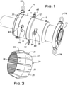
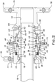
- a pipe fitting 10 includes an axially extending circular housing formed by annular grip, middle, and seal sections 11-13, respectively. These parts and various other parts described hereinbelow are generally fabricated of steel, with the exception of seals, and are annular in form except for some accessories or small parts.
- the sections 11-13 are coaxial and each preferably has an inside diameter surface 16-18 adapted to receive the outside diameter of a steel pipe 19 with a loose slip or sliding fit.
- a cylindrical skirt 21 on an inboard or inner end of the grip section 11 has internal threads 22 engaged with external threads 23 of a cylindrical extension 24 of the middle section 12. This enables the grip section 11 to be rigidly fixed to the middle section 12 with an end of the skirt 21 abutting a radial shoulder 25 of the middle section.
- the grip section 11 has several successive counterbores 26-28 inward of the internal skirt threads 22 for receiving a locking ring 31, an outer grip ring 32 and a seal 33, respectively.
- the seal 33 is an annulus of semi-rigid material, for example an elastomer, that fits on the exterior of the pipe 19 to exclude material from freely entering the housing or fitting 10 along the pipe exterior.
- a grip ring 34 shown in perspective in FIG. 3 is slotted partially along the length of the ring from alternating ends of the ring to form grip or gripping segments 36. Slots 35 enable the grip ring 34 to constrict radially onto the exterior of the pipe 19 as will be discussed below. Interior faces of the segments 36 can be serrated or otherwise treated to enhance their gripping capacity on the pipe 19.
- the segments 36 have a double-cone outer surface with one portion complementary to a conical bore of the outer grip ring 32 and an opposite portion complementary to a conical bore of a grip thrust ring in the form of an annular piston, hereinafter the grip piston 38.
- the grip piston 38 is disposed within the fitting 10 between the middle section 12 and grip section 11.
- the grip piston 38 is biased away from the grip ring 34 by a plurality of compression springs 39 distributed about the axis of the fitting and extending from associated pockets in the grip section body.
- An outside diameter of the grip piston 38 is threaded along a length 41 extending away from the middle section 12.
- the internally threaded locking ring 31 is engaged with the threads of the grip piston on the length 41.
- a skirt 43 of the grip piston 38 is telescoped in an annular blind space 44 formed in the middle section 12 and which serves as a piston chamber.
- An end face of the skirt 43 is fitted with annular seals 46, 47 that seal against the radially outer and inner walls of the piston chamber 44, respectively.
- the chamber 44 is in fluid communication with a hydraulic coupler 48 through a passage 49.
- the seal section 13 similar to the grip section 11, is a hollow circular body with a series of counterbores 51-53 for annular seals 56, a seal thrust ring or annular piston, hereafter seal piston 57 and annular extension 58 of the middle section 12 respectively.
- the seal section 13 is rigidly fixed to the middle section 12 by engagement of respective internal threads on the counterbore 53 and external threads on the middle section annular extension 58 with an end face 59 of the seal section 13 abutting a radial shoulder surface 61 of the middle section 12.
- the seals 56 are a suitable semi-rigid elastomer, known in the industry.
- the seals 56 are separated by a metal spacer ring 62.
- a groove 63 on the outer periphery of the spacer ring 62 communicates with a test port in the wall of the seal section 13.
- the seal piston 57 receives the pipe 19 through its central bore 66.
- a reduced diameter end section 67 of the seal piston 57 extends into the counterbore 51.
- the seal piston 57 is proportioned to slide on the pipe 19 and in the counterbore 51.
- the seal piston 57 has an annular extension 68, of increased inside diameter, received in an annular groove 69 formed in the adjacent face of the middle section 12.
- the annular groove 69 serves as a piston chamber for the seal piston extension 68.
- a hydraulic coupler 73 at the exterior of the fitting 10 communicates with the piston chamber 69 through a passage 74.
- a mechanical locking ring 76 is internally threaded and is received on mating external threads on the outside surface of the seal piston 57.
- a swivel lifting ring 77 is assembled in an external groove on the grip section 11. Hoist rings 78 are bolted to the seal section and swivel ring 77.
- the outboard end of the seal section 13 includes a flange 79 with bolt holes for connecting to a complementary flange of a pipe or other vessel.
- Other known connection or coupling structures, besides the illustrated flange 79, can be used with the disclosed fitting.
- the fitting 10 is installed by stabbing the end of the pipe 19 into the fitting so that its end is past the seals 56 and is supported by the surface 18 of the seal section 13.
- Hydraulic fluid pressurized up to 3000 psi for example, is introduced through the coupler 48 into the piston chamber 44. Hydraulic pressure on the piston skirt 43 causes the grip piston 38 to move axially in the fitting 10.
- a camming action between the conical surfaces of the grip piston 38 and complementary conical surfaces of the grip segments 36 causes the segments to constrict radially onto the exterior of the pipe 19. Limited axial movement of the grip segments 36 results in radial constriction of the distal or outboard length of the segments by camming action between the outer conical surfaces of the segments and inner conical surface of the outer grip ring 32.
- the grip piston 38 can be mechanically locked in the hydraulically extended position without regression of the grip piston by tightening the locking ring 31 threaded on the piston against the end face of the middle section 12.
- the threaded engagement between the locking ring 31 and grip piston affords infinite adjustment.
- the locking ring 31 has a series of spaced blind wrenching holes 82 distributed over its outer circumference as shown in FIG. 1 .
- the locking ring 31 is manually turned on the piston threads 41 by engaging a hole 82 with a wrenching bar through a slot 83 in the wall of the grip section 11.
- the locking ring 31, when deployed as just described, holds the grip piston 38 in its extended position tight against the grip ring 34 without back-sliding when the chamber 44 is exhausted of pressurized fluid. If a need exists to remove the fitting 10 from the pipe 19, the ring 31 can be re-wrenched away from the middle section 12 and the springs 39 will retract the grip piston 38 to release the grips 36.
- Pressurized hydraulic fluid again, up to 3000 psi, for example, applied to the coupler 73 extends the seal piston 57 to axially compress and radially inwardly extend the seals 56 onto the exterior of the pipe 19.
- the spacer ring 62 is slidable in the counterbore 51 enabling it to transfer compressive force to the axially outer seal.
- the sealing effectiveness of the seals 56 on the exterior of the pipe 19 can be tested by introducing a pressurized fluid into the test port 64 and observing whether leakage of such fluid through the seals occurs.
- the lock ring 76 threaded on the seal piston 57 is rotated to tightly abut against the respective end of the middle section 12 to mechanically lock the seal piston in place.
- Blind holes 84 in the periphery of the locking ring 76 accessible through an arcuate slot 86 in the wall of the seal section 13 and are engaged with a manually manipulated pin or wrench from the outside of the fitting 10 to manually tighten the locking ring against the middle section 21 effectively with infinite adjustability afforded by the interengaged threads.
- Axial compression on the seals can be released by backing the locking ring 76 off the middle section.
- Both access slots 83, 86 can be closed with a suitable elastomeric plug or the like.
- the piston area of the grip piston 38 is greater than that of the seal piston 57 so that where the same pressure source is used for each piston, the compressive strength of the seals 56 is not exceeded.
Landscapes
- Engineering & Computer Science (AREA)
- General Engineering & Computer Science (AREA)
- Mechanical Engineering (AREA)
- Physics & Mathematics (AREA)
- Fluid Mechanics (AREA)
- Actuator (AREA)
- Clamps And Clips (AREA)
- Quick-Acting Or Multi-Walled Pipe Joints (AREA)
- Gasket Seals (AREA)
- Earth Drilling (AREA)
Claims (10)
- Rohrfitting, umfassend ein ringförmiges Gehäuse, eine ringförmige Anordnung von Klemmen (36) in dem Gehäuse, eine axial von den Klemmen (36) beabstandete, ringförmige halbsteife Dichtung (56) in dem Gehäuse, einen hydraulischen Klemmenstellantrieb (38) in dem Gehäuse zum radialen Festspannen der Klemmen (36) in klemmende Anlage an einem Äußeren eines Rohrs, das sich in das Gehäuse erstreckt, und einen hydraulischen Dichtungsstellantrieb (57), der von dem Klemmenstellantrieb (38) hydraulisch und mechanisch unabhängig ist, zum radialen Zwingen der Dichtung in Anlage an einem Äußeren des Rohrs, eine erste mechanische Feststellvorrichtung (31) zum mechanischen Feststellen des hydraulischen Klemmenstellantriebs (38), um die Klemmen (36) mit dem Rohr in Kontakt zu halten, und eine zweite mechanische Feststellvorrichtung (76) zum mechanischen Feststellen des hydraulischen Dichtungsstellantriebs (57), um die Dichtung mit dem Rohr in Kontakt zu halten.
- Rohrfitting nach Anspruch 1, wobei der Klemmen- und der Dichtungsstellantrieb jeweilige ringförmige Kolben (38, 57) aufweisen, wobei die genannten mechanischen Feststellvorrichtungen angeordnet sind, um die ringförmigen Kolben unabhängig von der hydraulischen Druckbeaufschlagung der genannten Stellantriebe in ausgefahrenen Einsatzstellungen zu halten.
- Rohrfitting nach Anspruch 2, wobei die genannten mechanischen Feststellvorrichtungen jeweils auf das Außengewinde eines jeweiligen ringförmigen Kolbens (38, 57) aufgeschraubte, mit Innengewinde versehene Ringe (31, 57) sind.
- Rohrfitting nach Anspruch 1, wobei die Klemmen bogenförmige Klemmsegmente (36) umfassen, wobei der Klemmenstellantrieb einen ersten ringförmigen Kolben (38) und eine zugehörige Hydraulikkammer umfasst und der Dichtungsstellantrieb einen zweiten ringförmigen Kolben (57) und eine zugehörige Hydraulikkammer umfasst, die mechanisch und hydraulisch von dem ersten ringförmigen Kolben (38) und der zugehörigen Hydraulikkammer isoliert sind, und wobei das Fitting ferner einen ersten und einen zweiten separaten Hydraulikkreis umfasst, die jeweils von einem Äußeren des Gehäuses zu der Hydraulikkammer des ersten ringförmigen Kolbens bzw. der Hydraulikkammer des zweiten ringförmigen Kolbens verlaufen, wobei in den ersten Hydraulikkreis eingeführtes Druckfluid zum zwangsweisen Bewegen des ersten ringförmigen Kolbens (38) axial in Richtung auf die Klemmsegmente (36) wirksam ist, wobei Verkeilungsflächen so angeordnet sind, dass sie die Klemmsegmente (36) radial auf ein Rohr festspannen, das sich in das Gehäuse hinein erstreckt, und dadurch das Rohr in dem Gehäuse als Reaktion auf die axiale Bewegung des ersten ringförmigen Kolbens (38) in Richtung auf die Klemmsegmente (36) axial festhalten, wobei in die zweite Kammer eingeführtes Druckfluid zum zwangsweisen Bewegen des zweiten ringförmigen Kolbens (57) axial in Richtung auf die halbsteife Dichtung (56) wirksam ist, um die Dichtung (56) axial zusammenzudrücken, so dass sie auf das/dem Äußere(n) des Rohrs in dem Gehäuse axial festgespannt wird und abdichtet.
- Rohrfitting nach Anspruch 4, wobei die ringförmige halbsteife Dichtung zwei Ringe mit kreisförmigen Querschnitt (56) umfasst, die durch einen steifen Ring (62) getrennt sind, wobei ein axialer Zwischenraum zwischen den Ringen (56) durch eine Schaltung mit dem Äußeren des Gehäuses verbunden ist, um das Prüfen der Dichtungswirksamkeit der Ringe (56) auf dem Rohr zu ermöglichen.
- Rohrfitting nach Anspruch 4 oder Anspruch 5, wobei die ringförmigen Kolben (38, 57) in entgegengesetzter axialer Richtung ausgerichtet sind.
- Rohrfitting nach einem der Ansprüche 4 bis 6, wobei ein Äußeres des ersten ringförmigen Kolbens (38) mit Gewinde versehen ist und ein mit Innengewinde versehener Feststellring (31) auf dem Gewinde des ersten ringförmigen Kolbens montiert ist, wobei der Feststellring (31) auf dem ersten ringförmigen Kolben (38) drehbar ist, um den ersten ringförmigen Kolben (38) in einer ausgefahrenen Stellung festzustellen, um die Klemmsegmente (36) mechanisch in Anlage an dem Äußeren des Rohres zu halten.
- Rohrfitting nach einem der Ansprüche 4 bis 7, wobei ein Äußeres des zweiten ringförmigen Kolbens (57) mit Gewinde versehen ist und ein mit Innengewinde versehener Feststellring (76) auf dem Gewinde des zweiten ringförmigen Kolbens montiert ist, wobei der Feststellring (76) auf dem zweiten ringförmigen Kolben (57) drehbar ist, um den zweiten ringförmigen Kolben (57) in einer ausgefahrenen Stellung festzustellen, um die ringförmige halbsteife Dichtung (56) axial zusammengedrückt zu halten.
- Rohrfitting nach einem der Ansprüche 4 bis 8, wobei die genannte ringförmige Anordnung von Klemmsegmenten umfasst: Segmente (36) mit einer Doppelkonus-Außenfläche, so dass die Segmente (36) an entgegengesetzten axialen Enden der Anordnung zusammen einen Mindest-Außendurchmesser der ringförmigen Anordnung und auf halber Länge der Anordnung einen Höchst-Außendurchmesser bilden, wobei ein äußerer Klemmring in dem Gehäuse auf einer Seite der Anordnung, die dem ersten ringförmigen Kolben (38) entgegengesetzt ist, der Klemmring und der erste ringförmige Kolben (38) konische Bohrungen aufweisen, wobei die Klemmsegmentaußenfläche sowohl zu der konischen Bohrung des Klemmrings als auch zu der konischen Bohrung des ringförmigen Kolbens komplementär ist.
- Rohrfitting nach Anspruch 1, wobei das ringförmige Gehäuse drei ringförmige koaxiale Abschnitte, einschließlich eines Klemmabschnitts (11), eines mittleren Abschnitts (12) und eines Dichtungsabschnitts (13), umfasst, wobei der Klemmabschnitt (11) und der Dichtungsabschnitt (13) separat an dem mittleren Abschnitt (12) befestigt sind, wobei die Klemmen (36) im Klemmabschnitt (11) sind und die Dichtung (56) im Dichtungsabschnitt (13) ist.
Applications Claiming Priority (1)
| Application Number | Priority Date | Filing Date | Title |
|---|---|---|---|
| US15/872,305 US10571061B2 (en) | 2018-01-16 | 2018-01-16 | Independently hydraulically clamped and sealed fitting |
Publications (2)
| Publication Number | Publication Date |
|---|---|
| EP3517817A1 EP3517817A1 (de) | 2019-07-31 |
| EP3517817B1 true EP3517817B1 (de) | 2022-03-09 |
Family
ID=65033449
Family Applications (1)
| Application Number | Title | Priority Date | Filing Date |
|---|---|---|---|
| EP19151984.2A Active EP3517817B1 (de) | 2018-01-16 | 2019-01-15 | Unabhängig hydraulisch eingespannte und abgedichtete armatur |
Country Status (6)
| Country | Link |
|---|---|
| US (1) | US10571061B2 (de) |
| EP (1) | EP3517817B1 (de) |
| CN (1) | CN110043734B (de) |
| CA (1) | CA3030211C (de) |
| ES (1) | ES2909003T3 (de) |
| MX (1) | MX2019000688A (de) |
Families Citing this family (9)
| Publication number | Priority date | Publication date | Assignee | Title |
|---|---|---|---|---|
| CN112303355B (zh) * | 2020-11-03 | 2022-05-31 | 济宁鑫福源液压科技有限公司 | 一种独立的液压夹紧和密封的配合件 |
| US12618504B2 (en) | 2021-02-14 | 2026-05-05 | Entagral Engineering, Llc | Connector for subsea pipelines and risers, and repair of a pipeline or riser utilizing the connector |
| CN113687406A (zh) * | 2021-09-23 | 2021-11-23 | 中国工程物理研究院激光聚变研究中心 | 脉冲中子发射时间探测器 |
| CN116006823B (zh) * | 2022-12-29 | 2024-06-25 | 国家石油天然气管网集团有限公司 | 一种原油管道内检测器推送装置及推送方法 |
| CN116951211A (zh) * | 2023-08-03 | 2023-10-27 | 信达科创(唐山)石油设备有限公司 | 一种连续油管疲劳实验密封装置及密封方法 |
| CN118088559B (zh) * | 2024-04-24 | 2024-06-28 | 哈尔滨船舶锅炉涡轮机研究所(中国船舶集团有限公司第七0三研究所) | 一种用于船舶收放系统的旋转式液压传动装置 |
| CN119353524B (zh) * | 2024-12-25 | 2025-03-18 | 河南斯贝克仪表科技有限公司 | 一种接头快速连接器 |
| CN119778560B (zh) * | 2025-03-11 | 2025-05-13 | 温州市华海密封件有限公司 | 一种内置缓冲层的油气管道密封件 |
| CN120576292B (zh) * | 2025-08-06 | 2025-09-30 | 江苏爱索新材料科技有限公司 | 一种用于柔性内衬非开挖管道修复的高温防护焊接接头 |
Family Cites Families (32)
| Publication number | Priority date | Publication date | Assignee | Title |
|---|---|---|---|---|
| US3393926A (en) * | 1965-09-09 | 1968-07-23 | James F. Arnold | Hydraulic coupling |
| US3598429A (en) * | 1969-04-14 | 1971-08-10 | James F Arnold | Hydraulic coupling |
| US3713204A (en) * | 1970-04-30 | 1973-01-30 | Hydrocouple Corp | Method for connecting tubular members |
| US3711123A (en) * | 1971-01-15 | 1973-01-16 | Hydro Tech Services Inc | Apparatus for pressure testing annular seals in an oversliding connector |
| US3744822A (en) | 1971-01-15 | 1973-07-10 | Hydro Tech Services Inc | Apparatus for a sealing external surface of a tubular member |
| US3713675A (en) * | 1971-01-15 | 1973-01-30 | Hydro Tech Services Inc | Connector for tubular members |
| US3704033A (en) | 1971-01-15 | 1972-11-28 | Hydro Tech Services Inc | Connector for tubular members |
| US3784234A (en) | 1971-10-18 | 1974-01-08 | Hydrotech Int Inc | Hydraulic connector actuating apparatus |
| US3843167A (en) * | 1973-01-31 | 1974-10-22 | B Gronstedt | Hydraulically actuated pipe coupling |
| US3830526A (en) | 1973-04-26 | 1974-08-20 | Hydrotech Int Inc | Apparatus and method for making sub-sea connections |
| US3986728A (en) * | 1974-10-08 | 1976-10-19 | Hydrotech International, Inc. | Pipe coupling |
| US4109940A (en) * | 1975-01-27 | 1978-08-29 | Reneau Bobby J | Coupling apparatus |
| US3977702A (en) * | 1975-03-13 | 1976-08-31 | Hydrotech International, Inc. | Pipe coupling with retrievable setting means |
| US4006921A (en) * | 1975-06-10 | 1977-02-08 | Hydrotech International, Inc. | Pipe coupling |
| US4049297A (en) | 1975-12-15 | 1977-09-20 | Reneau Bobby J | Pipe coupling apparatus |
| US4078832A (en) | 1976-12-21 | 1978-03-14 | Hydrotech International, Inc. | Pipe coupling with improved seal means |
| US4290632A (en) * | 1979-01-08 | 1981-09-22 | Manchester Jr Luther L | Apparatus for connecting together flowline end portions |
| US4372584A (en) * | 1979-09-26 | 1983-02-08 | Big Inch Marine Systems, Inc. | Coupling for coupling tubular elements |
| US4381868A (en) * | 1981-07-24 | 1983-05-03 | Cameron Iron Works, Inc. | Pressure-actuated wellhead sealing assembly |
| US4728125A (en) * | 1986-01-10 | 1988-03-01 | Bobby J. Reneau | Grip and seal mechanically locking flowline connector |
| US4761023A (en) * | 1986-12-24 | 1988-08-02 | Cameron Iron Works, Inc. | Telescoping joint |
| US4832379A (en) | 1987-01-28 | 1989-05-23 | The Pipe Line Development Company | Collet grip riser fitting |
| US5158326A (en) | 1989-07-07 | 1992-10-27 | Cooper Industries, Inc. | Casing head connector |
| US5433482A (en) | 1993-08-16 | 1995-07-18 | Oceaneering International, Inc. | Weldless pipe repair apparatus and method |
| US5456501A (en) | 1993-08-25 | 1995-10-10 | Oceaneering, Inc. | Pipeline connection apparatus |
| NO20022196L (no) * | 2002-05-08 | 2009-11-16 | Advanced Prod & Loading As | Anordning for sammenkopling av rörledninger som förer fluid under trykk |
| WO2007102744A1 (en) | 2006-03-07 | 2007-09-13 | As Connector | Subsea pipeline repair and maintenance tools and method for replacement of broken pipelines |
| WO2010021754A1 (en) * | 2008-08-20 | 2010-02-25 | Lighthouse R & D Enterprises, Inc. | Apparatus for connecting tubular bodies and repairing underwater tubular bodies |
| CN102971567B (zh) * | 2010-05-03 | 2015-04-01 | 安捷伦科技有限公司 | 具有液压夹紧力元件的装配元件及相应的流体分离系统 |
| BR112014024680B1 (pt) * | 2012-04-05 | 2020-12-01 | National Oilwell Varco, L.P. | conector de local de poço, e, método para conectar componentes de um local de poço |
| EP3198184A4 (de) | 2014-09-26 | 2018-04-11 | Actuant Corporation | Vorrichtung und verfahren zur rohrreparatur |
| CN107387917B (zh) * | 2017-08-26 | 2023-04-07 | 山东圣鑫管业有限公司 | 一种用于压力机械液压管路的管接头装置 |
-
2018
- 2018-01-16 US US15/872,305 patent/US10571061B2/en active Active
-
2019
- 2019-01-14 CA CA3030211A patent/CA3030211C/en active Active
- 2019-01-15 ES ES19151984T patent/ES2909003T3/es active Active
- 2019-01-15 EP EP19151984.2A patent/EP3517817B1/de active Active
- 2019-01-16 CN CN201910040138.7A patent/CN110043734B/zh active Active
- 2019-01-16 MX MX2019000688A patent/MX2019000688A/es unknown
Also Published As
| Publication number | Publication date |
|---|---|
| MX2019000688A (es) | 2019-07-17 |
| US10571061B2 (en) | 2020-02-25 |
| US20190219210A1 (en) | 2019-07-18 |
| CN110043734B (zh) | 2022-03-29 |
| CA3030211A1 (en) | 2019-07-16 |
| EP3517817A1 (de) | 2019-07-31 |
| ES2909003T3 (es) | 2022-05-04 |
| CN110043734A (zh) | 2019-07-23 |
| CA3030211C (en) | 2022-08-09 |
Similar Documents
| Publication | Publication Date | Title |
|---|---|---|
| CA3030211C (en) | Independently hydraulically clamped and sealed fitting | |
| US3944263A (en) | Dynamic pipe coupling | |
| EP0272771B1 (de) | Teleskop-Verbindung | |
| US4045054A (en) | Apparatus for rigidly interconnecting misaligned pipe ends | |
| US4608739A (en) | Connector of and sealing of tubular members | |
| US4006921A (en) | Pipe coupling | |
| CA2367202C (en) | Pressure-containing plug for a tubular passageway | |
| EP0461741B1 (de) | Längenänderungen ausgleichende Verbindung | |
| WO2002036932A1 (en) | Apparatus and method for connecting tubular members | |
| US20230332726A1 (en) | Mechanical plug | |
| GB2448220A (en) | Hydraulic coupling with expansion chamber to prevent hydraulic lock | |
| WO2019125176A1 (en) | Pipe quick connector | |
| US4109940A (en) | Coupling apparatus | |
| US9303806B2 (en) | Closure assembly for pipe end | |
| AU7663194A (en) | Pipe connector | |
| EP2999908B1 (de) | Kopplervorrichtung und verfahren für deren verwendung | |
| HK40004875A (en) | Independently hydraulically clamped and sealed fitting | |
| MX2013012073A (es) | Aparato y metodo para empalmar conductos y mangueras submarinas. | |
| HK40004875B (zh) | 独立的液压夹紧和密封的配合件 | |
| NO348571B1 (en) | A female coupling element, a coupling assembly comprising the female coupling element, and a method for providing the coupling assembly | |
| WO2002063131A1 (en) | Coupling for transfer of fluids | |
| EP3338017B1 (de) | Flexible rohrverbindung |
Legal Events
| Date | Code | Title | Description |
|---|---|---|---|
| PUAI | Public reference made under article 153(3) epc to a published international application that has entered the european phase |
Free format text: ORIGINAL CODE: 0009012 |
|
| STAA | Information on the status of an ep patent application or granted ep patent |
Free format text: STATUS: THE APPLICATION HAS BEEN PUBLISHED |
|
| AK | Designated contracting states |
Kind code of ref document: A1 Designated state(s): AL AT BE BG CH CY CZ DE DK EE ES FI FR GB GR HR HU IE IS IT LI LT LU LV MC MK MT NL NO PL PT RO RS SE SI SK SM TR |
|
| AX | Request for extension of the european patent |
Extension state: BA ME |
|
| RIN1 | Information on inventor provided before grant (corrected) |
Inventor name: BEARD, GLENN Inventor name: MEENATHETHIL, SHON JOSEPH GEORGE Inventor name: LOUDEN, AARON Z |
|
| RIN1 | Information on inventor provided before grant (corrected) |
Inventor name: MEENATHETHIL, SHON JOSEPH GEORGE Inventor name: LOUDEN, AARON Z Inventor name: BEARD, GLENN |
|
| STAA | Information on the status of an ep patent application or granted ep patent |
Free format text: STATUS: REQUEST FOR EXAMINATION WAS MADE |
|
| 17P | Request for examination filed |
Effective date: 20200129 |
|
| RBV | Designated contracting states (corrected) |
Designated state(s): AL AT BE BG CH CY CZ DE DK EE ES FI FR GB GR HR HU IE IS IT LI LT LU LV MC MK MT NL NO PL PT RO RS SE SI SK SM TR |
|
| GRAP | Despatch of communication of intention to grant a patent |
Free format text: ORIGINAL CODE: EPIDOSNIGR1 |
|
| STAA | Information on the status of an ep patent application or granted ep patent |
Free format text: STATUS: GRANT OF PATENT IS INTENDED |
|
| INTG | Intention to grant announced |
Effective date: 20210908 |
|
| GRAS | Grant fee paid |
Free format text: ORIGINAL CODE: EPIDOSNIGR3 |
|
| GRAA | (expected) grant |
Free format text: ORIGINAL CODE: 0009210 |
|
| STAA | Information on the status of an ep patent application or granted ep patent |
Free format text: STATUS: THE PATENT HAS BEEN GRANTED |
|
| AK | Designated contracting states |
Kind code of ref document: B1 Designated state(s): AL AT BE BG CH CY CZ DE DK EE ES FI FR GB GR HR HU IE IS IT LI LT LU LV MC MK MT NL NO PL PT RO RS SE SI SK SM TR |
|
| REG | Reference to a national code |
Ref country code: CH Ref legal event code: EP Ref country code: AT Ref legal event code: REF Ref document number: 1474437 Country of ref document: AT Kind code of ref document: T Effective date: 20220315 |
|
| REG | Reference to a national code |
Ref country code: DE Ref legal event code: R096 Ref document number: 602019012245 Country of ref document: DE |
|
| REG | Reference to a national code |
Ref country code: IE Ref legal event code: FG4D |
|
| REG | Reference to a national code |
Ref country code: ES Ref legal event code: FG2A Ref document number: 2909003 Country of ref document: ES Kind code of ref document: T3 Effective date: 20220504 |
|
| RAP4 | Party data changed (patent owner data changed or rights of a patent transferred) |
Owner name: THE PIPE LINE DEVELOPMENT COMPANY |
|
| REG | Reference to a national code |
Ref country code: NO Ref legal event code: T2 Effective date: 20220309 |
|
| REG | Reference to a national code |
Ref country code: LT Ref legal event code: MG9D |
|
| REG | Reference to a national code |
Ref country code: NL Ref legal event code: MP Effective date: 20220309 |
|
| PG25 | Lapsed in a contracting state [announced via postgrant information from national office to epo] |
Ref country code: SE Free format text: LAPSE BECAUSE OF FAILURE TO SUBMIT A TRANSLATION OF THE DESCRIPTION OR TO PAY THE FEE WITHIN THE PRESCRIBED TIME-LIMIT Effective date: 20220309 Ref country code: RS Free format text: LAPSE BECAUSE OF FAILURE TO SUBMIT A TRANSLATION OF THE DESCRIPTION OR TO PAY THE FEE WITHIN THE PRESCRIBED TIME-LIMIT Effective date: 20220309 Ref country code: LT Free format text: LAPSE BECAUSE OF FAILURE TO SUBMIT A TRANSLATION OF THE DESCRIPTION OR TO PAY THE FEE WITHIN THE PRESCRIBED TIME-LIMIT Effective date: 20220309 Ref country code: HR Free format text: LAPSE BECAUSE OF FAILURE TO SUBMIT A TRANSLATION OF THE DESCRIPTION OR TO PAY THE FEE WITHIN THE PRESCRIBED TIME-LIMIT Effective date: 20220309 Ref country code: BG Free format text: LAPSE BECAUSE OF FAILURE TO SUBMIT A TRANSLATION OF THE DESCRIPTION OR TO PAY THE FEE WITHIN THE PRESCRIBED TIME-LIMIT Effective date: 20220609 |
|
| REG | Reference to a national code |
Ref country code: AT Ref legal event code: MK05 Ref document number: 1474437 Country of ref document: AT Kind code of ref document: T Effective date: 20220309 |
|
| PG25 | Lapsed in a contracting state [announced via postgrant information from national office to epo] |
Ref country code: LV Free format text: LAPSE BECAUSE OF FAILURE TO SUBMIT A TRANSLATION OF THE DESCRIPTION OR TO PAY THE FEE WITHIN THE PRESCRIBED TIME-LIMIT Effective date: 20220309 Ref country code: GR Free format text: LAPSE BECAUSE OF FAILURE TO SUBMIT A TRANSLATION OF THE DESCRIPTION OR TO PAY THE FEE WITHIN THE PRESCRIBED TIME-LIMIT Effective date: 20220610 Ref country code: FI Free format text: LAPSE BECAUSE OF FAILURE TO SUBMIT A TRANSLATION OF THE DESCRIPTION OR TO PAY THE FEE WITHIN THE PRESCRIBED TIME-LIMIT Effective date: 20220309 |
|
| PG25 | Lapsed in a contracting state [announced via postgrant information from national office to epo] |
Ref country code: NL Free format text: LAPSE BECAUSE OF FAILURE TO SUBMIT A TRANSLATION OF THE DESCRIPTION OR TO PAY THE FEE WITHIN THE PRESCRIBED TIME-LIMIT Effective date: 20220309 |
|
| PG25 | Lapsed in a contracting state [announced via postgrant information from national office to epo] |
Ref country code: SM Free format text: LAPSE BECAUSE OF FAILURE TO SUBMIT A TRANSLATION OF THE DESCRIPTION OR TO PAY THE FEE WITHIN THE PRESCRIBED TIME-LIMIT Effective date: 20220309 Ref country code: SK Free format text: LAPSE BECAUSE OF FAILURE TO SUBMIT A TRANSLATION OF THE DESCRIPTION OR TO PAY THE FEE WITHIN THE PRESCRIBED TIME-LIMIT Effective date: 20220309 Ref country code: RO Free format text: LAPSE BECAUSE OF FAILURE TO SUBMIT A TRANSLATION OF THE DESCRIPTION OR TO PAY THE FEE WITHIN THE PRESCRIBED TIME-LIMIT Effective date: 20220309 Ref country code: PT Free format text: LAPSE BECAUSE OF FAILURE TO SUBMIT A TRANSLATION OF THE DESCRIPTION OR TO PAY THE FEE WITHIN THE PRESCRIBED TIME-LIMIT Effective date: 20220711 Ref country code: EE Free format text: LAPSE BECAUSE OF FAILURE TO SUBMIT A TRANSLATION OF THE DESCRIPTION OR TO PAY THE FEE WITHIN THE PRESCRIBED TIME-LIMIT Effective date: 20220309 Ref country code: CZ Free format text: LAPSE BECAUSE OF FAILURE TO SUBMIT A TRANSLATION OF THE DESCRIPTION OR TO PAY THE FEE WITHIN THE PRESCRIBED TIME-LIMIT Effective date: 20220309 Ref country code: AT Free format text: LAPSE BECAUSE OF FAILURE TO SUBMIT A TRANSLATION OF THE DESCRIPTION OR TO PAY THE FEE WITHIN THE PRESCRIBED TIME-LIMIT Effective date: 20220309 |
|
| PG25 | Lapsed in a contracting state [announced via postgrant information from national office to epo] |
Ref country code: PL Free format text: LAPSE BECAUSE OF FAILURE TO SUBMIT A TRANSLATION OF THE DESCRIPTION OR TO PAY THE FEE WITHIN THE PRESCRIBED TIME-LIMIT Effective date: 20220309 Ref country code: IS Free format text: LAPSE BECAUSE OF FAILURE TO SUBMIT A TRANSLATION OF THE DESCRIPTION OR TO PAY THE FEE WITHIN THE PRESCRIBED TIME-LIMIT Effective date: 20220709 Ref country code: AL Free format text: LAPSE BECAUSE OF FAILURE TO SUBMIT A TRANSLATION OF THE DESCRIPTION OR TO PAY THE FEE WITHIN THE PRESCRIBED TIME-LIMIT Effective date: 20220309 |
|
| REG | Reference to a national code |
Ref country code: DE Ref legal event code: R097 Ref document number: 602019012245 Country of ref document: DE |
|
| PLBE | No opposition filed within time limit |
Free format text: ORIGINAL CODE: 0009261 |
|
| STAA | Information on the status of an ep patent application or granted ep patent |
Free format text: STATUS: NO OPPOSITION FILED WITHIN TIME LIMIT |
|
| PG25 | Lapsed in a contracting state [announced via postgrant information from national office to epo] |
Ref country code: DK Free format text: LAPSE BECAUSE OF FAILURE TO SUBMIT A TRANSLATION OF THE DESCRIPTION OR TO PAY THE FEE WITHIN THE PRESCRIBED TIME-LIMIT Effective date: 20220309 |
|
| 26N | No opposition filed |
Effective date: 20221212 |
|
| PG25 | Lapsed in a contracting state [announced via postgrant information from national office to epo] |
Ref country code: SI Free format text: LAPSE BECAUSE OF FAILURE TO SUBMIT A TRANSLATION OF THE DESCRIPTION OR TO PAY THE FEE WITHIN THE PRESCRIBED TIME-LIMIT Effective date: 20220309 |
|
| REG | Reference to a national code |
Ref country code: DE Ref legal event code: R119 Ref document number: 602019012245 Country of ref document: DE |
|
| REG | Reference to a national code |
Ref country code: CH Ref legal event code: PL |
|
| PG25 | Lapsed in a contracting state [announced via postgrant information from national office to epo] |
Ref country code: LU Free format text: LAPSE BECAUSE OF NON-PAYMENT OF DUE FEES Effective date: 20230115 |
|
| REG | Reference to a national code |
Ref country code: BE Ref legal event code: MM Effective date: 20230131 |
|
| PG25 | Lapsed in a contracting state [announced via postgrant information from national office to epo] |
Ref country code: LI Free format text: LAPSE BECAUSE OF NON-PAYMENT OF DUE FEES Effective date: 20230131 Ref country code: DE Free format text: LAPSE BECAUSE OF NON-PAYMENT OF DUE FEES Effective date: 20230801 Ref country code: CH Free format text: LAPSE BECAUSE OF NON-PAYMENT OF DUE FEES Effective date: 20230131 |
|
| PG25 | Lapsed in a contracting state [announced via postgrant information from national office to epo] |
Ref country code: BE Free format text: LAPSE BECAUSE OF NON-PAYMENT OF DUE FEES Effective date: 20230131 |
|
| PG25 | Lapsed in a contracting state [announced via postgrant information from national office to epo] |
Ref country code: MC Free format text: LAPSE BECAUSE OF FAILURE TO SUBMIT A TRANSLATION OF THE DESCRIPTION OR TO PAY THE FEE WITHIN THE PRESCRIBED TIME-LIMIT Effective date: 20220309 |
|
| PG25 | Lapsed in a contracting state [announced via postgrant information from national office to epo] |
Ref country code: MC Free format text: LAPSE BECAUSE OF FAILURE TO SUBMIT A TRANSLATION OF THE DESCRIPTION OR TO PAY THE FEE WITHIN THE PRESCRIBED TIME-LIMIT Effective date: 20220309 |
|
| PG25 | Lapsed in a contracting state [announced via postgrant information from national office to epo] |
Ref country code: CY Free format text: LAPSE BECAUSE OF FAILURE TO SUBMIT A TRANSLATION OF THE DESCRIPTION OR TO PAY THE FEE WITHIN THE PRESCRIBED TIME-LIMIT; INVALID AB INITIO Effective date: 20190115 |
|
| PG25 | Lapsed in a contracting state [announced via postgrant information from national office to epo] |
Ref country code: HU Free format text: LAPSE BECAUSE OF FAILURE TO SUBMIT A TRANSLATION OF THE DESCRIPTION OR TO PAY THE FEE WITHIN THE PRESCRIBED TIME-LIMIT; INVALID AB INITIO Effective date: 20190115 |
|
| PGFP | Annual fee paid to national office [announced via postgrant information from national office to epo] |
Ref country code: GB Payment date: 20260114 Year of fee payment: 8 |
|
| PGFP | Annual fee paid to national office [announced via postgrant information from national office to epo] |
Ref country code: ES Payment date: 20260213 Year of fee payment: 8 |
|
| PGFP | Annual fee paid to national office [announced via postgrant information from national office to epo] |
Ref country code: NO Payment date: 20260120 Year of fee payment: 8 Ref country code: IE Payment date: 20260114 Year of fee payment: 8 |
|
| PGFP | Annual fee paid to national office [announced via postgrant information from national office to epo] |
Ref country code: IT Payment date: 20260116 Year of fee payment: 8 |
|
| PGFP | Annual fee paid to national office [announced via postgrant information from national office to epo] |
Ref country code: FR Payment date: 20260115 Year of fee payment: 8 |
|
| PGFP | Annual fee paid to national office [announced via postgrant information from national office to epo] |
Ref country code: TR Payment date: 20260108 Year of fee payment: 8 |