EP3517833A1 - Automobilteil, verfahren und vorrichtung zur herstellung einer automobilbeleuchtungsvorrichtung sowie automobilbeleuchtungsvorrichtung - Google Patents
Automobilteil, verfahren und vorrichtung zur herstellung einer automobilbeleuchtungsvorrichtung sowie automobilbeleuchtungsvorrichtung Download PDFInfo
- Publication number
- EP3517833A1 EP3517833A1 EP18382048.9A EP18382048A EP3517833A1 EP 3517833 A1 EP3517833 A1 EP 3517833A1 EP 18382048 A EP18382048 A EP 18382048A EP 3517833 A1 EP3517833 A1 EP 3517833A1
- Authority
- EP
- European Patent Office
- Prior art keywords
- wall
- automotive
- lighting device
- distance
- height
- Prior art date
- Legal status (The legal status is an assumption and is not a legal conclusion. Google has not performed a legal analysis and makes no representation as to the accuracy of the status listed.)
- Withdrawn
Links
Images


Classifications
-
- B—PERFORMING OPERATIONS; TRANSPORTING
- B60—VEHICLES IN GENERAL
- B60R—VEHICLES, VEHICLE FITTINGS, OR VEHICLE PARTS, NOT OTHERWISE PROVIDED FOR
- B60R16/00—Electric or fluid circuits specially adapted for vehicles and not otherwise provided for; Arrangement of elements of electric or fluid circuits specially adapted for vehicles and not otherwise provided for
- B60R16/02—Electric or fluid circuits specially adapted for vehicles and not otherwise provided for; Arrangement of elements of electric or fluid circuits specially adapted for vehicles and not otherwise provided for electric constitutive elements
- B60R16/0207—Wire harnesses
- B60R16/0215—Protecting, fastening and routing means therefor
-
- B—PERFORMING OPERATIONS; TRANSPORTING
- B29—WORKING OF PLASTICS; WORKING OF SUBSTANCES IN A PLASTIC STATE IN GENERAL
- B29C—SHAPING OR JOINING OF PLASTICS; SHAPING OF MATERIAL IN A PLASTIC STATE, NOT OTHERWISE PROVIDED FOR; AFTER-TREATMENT OF THE SHAPED PRODUCTS, e.g. REPAIRING
- B29C53/00—Shaping by bending, folding, twisting, straightening or flattening; Apparatus therefor
- B29C53/02—Bending or folding
-
- B—PERFORMING OPERATIONS; TRANSPORTING
- B60—VEHICLES IN GENERAL
- B60Q—ARRANGEMENT OF SIGNALLING OR LIGHTING DEVICES, THE MOUNTING OR SUPPORTING THEREOF OR CIRCUITS THEREFOR, FOR VEHICLES IN GENERAL
- B60Q1/00—Arrangement of optical signalling or lighting devices, the mounting or supporting thereof or circuits therefor
- B60Q1/0088—Details of electrical connections
-
- F—MECHANICAL ENGINEERING; LIGHTING; HEATING; WEAPONS; BLASTING
- F21—LIGHTING
- F21S—NON-PORTABLE LIGHTING DEVICES; SYSTEMS THEREOF; VEHICLE LIGHTING DEVICES SPECIALLY ADAPTED FOR VEHICLE EXTERIORS
- F21S45/00—Arrangements within vehicle lighting devices specially adapted for vehicle exteriors, for purposes other than emission or distribution of light
-
- F—MECHANICAL ENGINEERING; LIGHTING; HEATING; WEAPONS; BLASTING
- F21—LIGHTING
- F21V—FUNCTIONAL FEATURES OR DETAILS OF LIGHTING DEVICES OR SYSTEMS THEREOF; STRUCTURAL COMBINATIONS OF LIGHTING DEVICES WITH OTHER ARTICLES, NOT OTHERWISE PROVIDED FOR
- F21V27/00—Cable-stowing arrangements structurally associated with lighting devices, e.g. reels
-
- H—ELECTRICITY
- H02—GENERATION; CONVERSION OR DISTRIBUTION OF ELECTRIC POWER
- H02G—INSTALLATION OF ELECTRIC CABLES OR LINES, OR OF COMBINED OPTICAL AND ELECTRIC CABLES OR LINES
- H02G3/00—Installations of electric cables or lines or protective tubing therefor in or on buildings, equivalent structures or vehicles
- H02G3/30—Installations of cables or lines on walls, floors or ceilings
-
- B—PERFORMING OPERATIONS; TRANSPORTING
- B60—VEHICLES IN GENERAL
- B60R—VEHICLES, VEHICLE FITTINGS, OR VEHICLE PARTS, NOT OTHERWISE PROVIDED FOR
- B60R11/00—Arrangements for holding or mounting articles, not otherwise provided for
- B60R2011/0042—Arrangements for holding or mounting articles, not otherwise provided for characterised by mounting means
- B60R2011/008—Adjustable or movable supports
-
- F—MECHANICAL ENGINEERING; LIGHTING; HEATING; WEAPONS; BLASTING
- F21—LIGHTING
- F21W—INDEXING SCHEME ASSOCIATED WITH SUBCLASSES F21K, F21L, F21S and F21V, RELATING TO USES OR APPLICATIONS OF LIGHTING DEVICES OR SYSTEMS
- F21W2107/00—Use or application of lighting devices on or in particular types of vehicles
- F21W2107/10—Use or application of lighting devices on or in particular types of vehicles for land vehicles
Definitions
- This invention is related to the field of automotive lighting devices.
- wires harnesses are located uncontrolledly along the inner surface of the housing. Spare portions are loose, so they may be entangled or even cut by other elements. This may happen during the lifetime of the lighting device or even in the manufacturing process.
- a harness is gathered by a flange, and then this flange is attached to the inner surface of the housing. This avoids the conductive wires being freely arranged in the interior of the housing, but sometimes is not enough to prevent the conductive wires from being accidentally cut or trapped between two elements, mostly in their manufacturing process.
- the invention provides a solution for this problem by means of an automotive part according to claim 1 a method according to claim 6 and an apparatus according to claim 11.
- Preferred embodiments of the invention are defined in dependent claims.
- the invention provides an automotive part for manufacturing an automotive lighting device housing.
- This automotive part comprises
- the wall distance would therefore be the minimum distance between the first wall and the second wall.
- This automotive part may be manufactured as a final product, and is suitable for manufacturing an automotive lighting device housing by bending the first wall over the second wall and encompassing some conductive wires inside.
- the first height is at least 1.5 times the wall distance and the main thickness is lower than 0.2 times the first height.
- the automotive part is made of at least one of polypropylene, acrylonitrile butadiene styrene, poly-carbonate and preferably doped with talc and/or glass.
- the first wall is parallel to the second wall and the distance between them is comprised between 2 and 8 cm.
- the parallel arrangement optimizes the space between the walls, so that the conductive wires may run between them. This distance is fairly enough for the conductive wires used in the majority of automotive lighting devices.
- the first height is comprised between 3 and 20 cm. This height is also usually enough for providing a spare portion in the first wall to be bended over the second wall.
- the first wall has an upper portion with a thickness lower than the main thickness, the upper portion being further from the inner surface than the point where the main thickness is measured.
- This decreasing thickness saves material and weight without compromising reliability.
- the invention provides a method for manufacturing an automotive lighting device housing, the method comprising the steps of
- This method is suitable for manufacturing an automotive lighting device housing which has conductive wires in contact with the housing and reducing the risk of entangling.
- the step of heating at least a portion of the first wall is performed by means of a wire which is put at a distance between 1 and 25 mm from the heating portion.
- a hot wire is used to heat the heating portion of the first wall. This distance is enough to cause this heating effect without damaging this part.
- the step of bending the first wall over the second wall is performed until the first wall makes contact with the second wall.
- This contact is one of the possibilities to ensure a correct closure of the space between the first and the second wall.
- the step of bending the first wall over the second wall is performed following a line parallel to the housing.
- the step of bending the first wall over the second wall is performed following a line which is not parallel to the housing.
- the invention provides an apparatus for performing the steps of a method according to the preceding inventive aspect, the apparatus comprising
- the apparatus further comprises a wire retainer suitable for limiting the position of a plurality of wires while the bending element is rotated around the hinge.
- the invention provides an automotive lighting device comprising an automotive lighting device housing manufactured by a method according to the invention.
- This automotive lighting device has conductive wires in contact with the housing and reduces the risk of entangling. Hence, this automotive lighting device is more reliable and robust.
- Figures 1a to 1d shows some steps of a method for manufacturing an automotive lighting device according to the invention.
- Figure 1a shows a first step of this method.
- This automotive part 20 is made of acrylonitrile butadiene styrene and comprises
- the first wall 31 protrudes a first height h1 from the inner surface 21 and has a main thickness t1.
- the second wall 32 in turn protrudes a second height h2 from the inner surface 21.
- the main thickness t1 is measured in the separation direction sd at a distance from the inner surface equal to the second height h2. This means that the main thickness t1 is not measured in the portion of the first wall 31 which is at the inner surface 21, and is not measured in the portion of the first wall 31 which is farthest from the inner surface 21, but approximately half way: in a point which is a distance from the inner surface equal to the second height h2. Further, this main thickness t1 is measured in the separation direction sd, which is given by the two points of the first and second wall which are closest between them. In the event these first and second walls are parallel, the separation direction is the direction perpendicular to both of them.
- the thickness of the first wall 31 may not be constant, and is not constant in this embodiment.
- the first wall 31 has an upper portion with a thickness lower than the main thickness t1. This upper portion being further from the inner surface 21 than the point where the main thickness t1 is measured. Hence, the thickness of the first wall 31 diminishes with the distance from the inner surface 21.
- This second wall 32 is located at a wall distance wd from the first wall 31.
- the wall distance wd is measured in the separation direction sd: in the event the first and second walls are parallel, this wall distance wd is the distance between the parallel walls.
- the first height h1 is in this embodiment twice the wall distance wd and the main thickness t1 is 0.05 times the wall distance wd. Hence, the first wall 31 being therefore suitable for being bent over the second wall 32. In this embodiment, the first wall 31 is parallel to the second wall 32 and the distance between them is 5 cm. The first height h1 is therefore 10 cm.
- Figure 1b shows a second step of this method.
- a plurality of conductive wires 3 is provided between first wall 31 and the second wall 32. These conductive wires 3 are intended to provide electrical supply and signals to a lighting module contained in the automotive lighting device.
- FIG. 1c shows a third step of this method.
- an apparatus 40 suitable for carrying out this step is provided.
- This apparatus 40 comprises a heating element 41, a bending element 42 rotatable around a hinge and a wire retainer 43.
- the heating element 41 is located near a heating portion 30 of the first wall 31 and the bending element 42 is located near the first wall 31. In these embodiments, the heating element 41 is located at a suitable distance of the heating portion 30, preferably 10 mm, not to damage it.
- This step includes heating the heating portion 30 of the first wall 31 with the heating element 41 and then bending the first wall 31 over the second wall 32 by rotating the bending element 42 around the hinge over the upper portion of the first wall 31, so that the plurality of conductive wires 3 are surrounded by the first 31 and second 32 walls and a portion of the inner surface 21 of the housing 2.
- the wire retainer 43 ensures the correct position of the conductive wires 3 during all the process.
- the first wall 31 is bent over the second wall 32 until the first wall 31 makes contact with the second wall 32.
- there are other ways of ensuring the correct closure of this region such as a small bending in the second wall, which makes this contact unnecessary.
- Figure 1d shows the lighting device housing which results from these steps.
- the conductive wires 3 are enclosed by the first wall 31, the second wall 32 and a portion of the inner surface 21 of the housing 2. As a consequence, they are perfectly limited, thus reducing the risk of cutting, trapping or entangling.
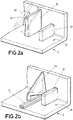
- Figure 2a shows an alternative scenario for this third step.
- the first 31 and the second 32 walls are also limited by a vertical wall of the housing 2.
- the heating element 41 and the bending element 42 are arranged following a diagonal line, so that a substantially triangular portion of the first wall 31 is bent over the second wall 32.
- Figure 2b shows the lighting device housing which results from these steps.
- the conductive wires 3 are enclosed by the first wall 31, the second wall 32 and a portion of the inner surface 21 of the housing 2, although in a different way from the housing of Figure 1d .
- they are also perfectly limited, thus reducing the risk of cutting, trapping or entangling.
- Figure 3 shows an automotive vehicle 100 with an automotive lighting device 1 comprising an automotive lighting device housing 2 manufactured by a method according to the invention.
Landscapes
- Engineering & Computer Science (AREA)
- Mechanical Engineering (AREA)
- General Engineering & Computer Science (AREA)
- Architecture (AREA)
- Civil Engineering (AREA)
- Structural Engineering (AREA)
- Non-Portable Lighting Devices Or Systems Thereof (AREA)
- Arrangements Of Lighting Devices For Vehicle Interiors, Mounting And Supporting Thereof, Circuits Therefore (AREA)
- Lighting Device Outwards From Vehicle And Optical Signal (AREA)
Priority Applications (3)
| Application Number | Priority Date | Filing Date | Title |
|---|---|---|---|
| EP18382048.9A EP3517833A1 (de) | 2018-01-29 | 2018-01-29 | Automobilteil, verfahren und vorrichtung zur herstellung einer automobilbeleuchtungsvorrichtung sowie automobilbeleuchtungsvorrichtung |
| CN201910083200.0A CN110094704A (zh) | 2018-01-29 | 2019-01-28 | 车用部件、用于制造车用照明装置的方法和设备以及车用照明装置 |
| US16/260,396 US20190232896A1 (en) | 2018-01-29 | 2019-01-29 | Automotive part, method and apparatus for manufacturing an automotive lighting device and automotive lighting device |
Applications Claiming Priority (1)
| Application Number | Priority Date | Filing Date | Title |
|---|---|---|---|
| EP18382048.9A EP3517833A1 (de) | 2018-01-29 | 2018-01-29 | Automobilteil, verfahren und vorrichtung zur herstellung einer automobilbeleuchtungsvorrichtung sowie automobilbeleuchtungsvorrichtung |
Publications (1)
| Publication Number | Publication Date |
|---|---|
| EP3517833A1 true EP3517833A1 (de) | 2019-07-31 |
Family
ID=61187246
Family Applications (1)
| Application Number | Title | Priority Date | Filing Date |
|---|---|---|---|
| EP18382048.9A Withdrawn EP3517833A1 (de) | 2018-01-29 | 2018-01-29 | Automobilteil, verfahren und vorrichtung zur herstellung einer automobilbeleuchtungsvorrichtung sowie automobilbeleuchtungsvorrichtung |
Country Status (3)
| Country | Link |
|---|---|
| US (1) | US20190232896A1 (de) |
| EP (1) | EP3517833A1 (de) |
| CN (1) | CN110094704A (de) |
Cited By (1)
| Publication number | Priority date | Publication date | Assignee | Title |
|---|---|---|---|---|
| DE102019121165A1 (de) * | 2019-08-06 | 2021-02-11 | Trilux Gmbh & Co. Kg | System zur Realisierung einer Leuchte mit elektrischem Abgriff mit Leiterhalter |
Families Citing this family (2)
| Publication number | Priority date | Publication date | Assignee | Title |
|---|---|---|---|---|
| US11040674B1 (en) * | 2019-12-17 | 2021-06-22 | Valeo North America, Inc. | Mold-in cable, wire harness and component retainer |
| JP7496738B2 (ja) * | 2020-08-24 | 2024-06-07 | 大和化成工業株式会社 | ワイヤーハーネスの配策構造 |
Citations (7)
| Publication number | Priority date | Publication date | Assignee | Title |
|---|---|---|---|---|
| JPS4884383U (de) * | 1972-01-12 | 1973-10-13 | ||
| JPS59103303U (ja) * | 1982-12-28 | 1984-07-11 | 市光工業株式会社 | 車輛用灯具 |
| JPS61171109U (de) * | 1985-04-15 | 1986-10-23 | ||
| DE10120099C1 (de) * | 2001-04-25 | 2002-09-12 | Brose Fahrzeugteile | Trägerplatte einer Kraftfahrzeugtür |
| JP2004136711A (ja) * | 2002-10-15 | 2004-05-13 | Sumitomo Wiring Syst Ltd | ワイヤハーネスの車体固定構造 |
| JP2004320830A (ja) * | 2003-04-11 | 2004-11-11 | Fujikura Ltd | ハーネスの固定構造 |
| DE202013101944U1 (de) * | 2013-05-06 | 2013-05-28 | Hella Kgaa Hueck & Co. | Anordnung eines Kabelführungselementes im Gehäuse einer Beleuchtungseinrichtung für ein Fahrzeug |
Family Cites Families (3)
| Publication number | Priority date | Publication date | Assignee | Title |
|---|---|---|---|---|
| CN103453491A (zh) * | 2012-05-31 | 2013-12-18 | 海洋王照明科技股份有限公司 | 一种灯具及电缆线卡 |
| JP6535091B2 (ja) * | 2014-11-25 | 2019-06-26 | ボルボトラックコーポレーション | 車両の支持構造体にワイヤーハーネスを取り付ける自己締結ブラケット、及び、これを備えた車両 |
| CN205239397U (zh) * | 2015-12-15 | 2016-05-18 | 上汽依维柯红岩商用车有限公司 | 重型汽车驾驶室电缆管束固定支架 |
-
2018
- 2018-01-29 EP EP18382048.9A patent/EP3517833A1/de not_active Withdrawn
-
2019
- 2019-01-28 CN CN201910083200.0A patent/CN110094704A/zh active Pending
- 2019-01-29 US US16/260,396 patent/US20190232896A1/en not_active Abandoned
Patent Citations (7)
| Publication number | Priority date | Publication date | Assignee | Title |
|---|---|---|---|---|
| JPS4884383U (de) * | 1972-01-12 | 1973-10-13 | ||
| JPS59103303U (ja) * | 1982-12-28 | 1984-07-11 | 市光工業株式会社 | 車輛用灯具 |
| JPS61171109U (de) * | 1985-04-15 | 1986-10-23 | ||
| DE10120099C1 (de) * | 2001-04-25 | 2002-09-12 | Brose Fahrzeugteile | Trägerplatte einer Kraftfahrzeugtür |
| JP2004136711A (ja) * | 2002-10-15 | 2004-05-13 | Sumitomo Wiring Syst Ltd | ワイヤハーネスの車体固定構造 |
| JP2004320830A (ja) * | 2003-04-11 | 2004-11-11 | Fujikura Ltd | ハーネスの固定構造 |
| DE202013101944U1 (de) * | 2013-05-06 | 2013-05-28 | Hella Kgaa Hueck & Co. | Anordnung eines Kabelführungselementes im Gehäuse einer Beleuchtungseinrichtung für ein Fahrzeug |
Cited By (1)
| Publication number | Priority date | Publication date | Assignee | Title |
|---|---|---|---|---|
| DE102019121165A1 (de) * | 2019-08-06 | 2021-02-11 | Trilux Gmbh & Co. Kg | System zur Realisierung einer Leuchte mit elektrischem Abgriff mit Leiterhalter |
Also Published As
| Publication number | Publication date |
|---|---|
| CN110094704A (zh) | 2019-08-06 |
| US20190232896A1 (en) | 2019-08-01 |
Similar Documents
| Publication | Publication Date | Title |
|---|---|---|
| US20190232896A1 (en) | Automotive part, method and apparatus for manufacturing an automotive lighting device and automotive lighting device | |
| US9673585B2 (en) | Rotary connector having a cable in a wiring space between a rotary body and a housing | |
| US20180268959A1 (en) | Electrical cable, terminal-equipped electrical cable, and method of manufacturing terminal-equipped electrical cable | |
| CA2969215A1 (en) | Plug | |
| CN103457049B (zh) | 端子保护罩以及电气接线箱 | |
| CN104008815A (zh) | 用于数据通信电缆的不连续屏蔽带 | |
| EP3763575B1 (de) | Kabelbaum, kabelbaumherstellungsverfahren und kabelbaumherstellungsvorrichtung | |
| CN111446029B (zh) | 汇流条电线 | |
| US8633388B2 (en) | Attaching structure of banding band | |
| JP2014229562A (ja) | ワイヤーハーネス及び中継ハーネス | |
| AU2014303737A1 (en) | Structure for routing power supply cables to electrically heated wire terminals | |
| US11017920B2 (en) | Vehicle wire harness for suppressing localized uneven progression of wear in connector terminals and manufacturing method of wire harness | |
| KR20180003097U (ko) | 케이블 덕트 | |
| EP3822127B1 (de) | Stromanschlusskasten | |
| US9437351B2 (en) | Shield wire for wiring harness and method of making the same | |
| EP3489578A1 (de) | Beleuchtungsvorrichtung und verfahren zur herstellung einer beleuchtungsvorrichtung | |
| US20170033504A1 (en) | Connector | |
| US10069286B2 (en) | Insulation structure for splice portion, harness mounting plate, and wiring unit | |
| US20150236489A1 (en) | Electrical junction box | |
| JP6383199B2 (ja) | 電線端末処理構造 | |
| JP2015050030A (ja) | 端子付きフラットケーブルおよびフラットケーブル | |
| EP3637564A1 (de) | Verfahren zur herstellung einer elektrischen verdrahtungsanordnung und nach diesem verfahren hergestellte elektrische verdrahtungsanordnung | |
| JP2009245713A (ja) | シールドケーブル及びシールドケーブルの製造方法 | |
| CN222381885U (zh) | 电气模块 | |
| KR102038492B1 (ko) | 와이어 하네스 및 그의 제조방법 |
Legal Events
| Date | Code | Title | Description |
|---|---|---|---|
| PUAI | Public reference made under article 153(3) epc to a published international application that has entered the european phase |
Free format text: ORIGINAL CODE: 0009012 |
|
| STAA | Information on the status of an ep patent application or granted ep patent |
Free format text: STATUS: THE APPLICATION HAS BEEN PUBLISHED |
|
| AK | Designated contracting states |
Kind code of ref document: A1 Designated state(s): AL AT BE BG CH CY CZ DE DK EE ES FI FR GB GR HR HU IE IS IT LI LT LU LV MC MK MT NL NO PL PT RO RS SE SI SK SM TR |
|
| AX | Request for extension of the european patent |
Extension state: BA ME |
|
| STAA | Information on the status of an ep patent application or granted ep patent |
Free format text: STATUS: REQUEST FOR EXAMINATION WAS MADE |
|
| 17P | Request for examination filed |
Effective date: 20200130 |
|
| RBV | Designated contracting states (corrected) |
Designated state(s): AL AT BE BG CH CY CZ DE DK EE ES FI FR GB GR HR HU IE IS IT LI LT LU LV MC MK MT NL NO PL PT RO RS SE SI SK SM TR |
|
| STAA | Information on the status of an ep patent application or granted ep patent |
Free format text: STATUS: THE APPLICATION IS DEEMED TO BE WITHDRAWN |
|
| 18D | Application deemed to be withdrawn |
Effective date: 20200201 |