EP3517856A1 - Procédé et appareil de confirmation d'étalonnage d'un détecteur de fluide frigorigène - Google Patents
Procédé et appareil de confirmation d'étalonnage d'un détecteur de fluide frigorigène Download PDFInfo
- Publication number
- EP3517856A1 EP3517856A1 EP18205206.8A EP18205206A EP3517856A1 EP 3517856 A1 EP3517856 A1 EP 3517856A1 EP 18205206 A EP18205206 A EP 18205206A EP 3517856 A1 EP3517856 A1 EP 3517856A1
- Authority
- EP
- European Patent Office
- Prior art keywords
- refrigerant
- orifice
- valve
- mixing device
- detector
- Prior art date
- Legal status (The legal status is an assumption and is not a legal conclusion. Google has not performed a legal analysis and makes no representation as to the accuracy of the status listed.)
- Granted
Links
Images


Classifications
-
- F—MECHANICAL ENGINEERING; LIGHTING; HEATING; WEAPONS; BLASTING
- F25—REFRIGERATION OR COOLING; COMBINED HEATING AND REFRIGERATION SYSTEMS; HEAT PUMP SYSTEMS; MANUFACTURE OR STORAGE OF ICE; LIQUEFACTION SOLIDIFICATION OF GASES
- F25B—REFRIGERATION MACHINES, PLANTS OR SYSTEMS; COMBINED HEATING AND REFRIGERATION SYSTEMS; HEAT PUMP SYSTEMS
- F25B49/00—Arrangement or mounting of control or safety devices
- F25B49/005—Arrangement or mounting of control or safety devices of safety devices
-
- F—MECHANICAL ENGINEERING; LIGHTING; HEATING; WEAPONS; BLASTING
- F25—REFRIGERATION OR COOLING; COMBINED HEATING AND REFRIGERATION SYSTEMS; HEAT PUMP SYSTEMS; MANUFACTURE OR STORAGE OF ICE; LIQUEFACTION SOLIDIFICATION OF GASES
- F25B—REFRIGERATION MACHINES, PLANTS OR SYSTEMS; COMBINED HEATING AND REFRIGERATION SYSTEMS; HEAT PUMP SYSTEMS
- F25B13/00—Compression machines, plants or systems, with reversible cycle
-
- F—MECHANICAL ENGINEERING; LIGHTING; HEATING; WEAPONS; BLASTING
- F25—REFRIGERATION OR COOLING; COMBINED HEATING AND REFRIGERATION SYSTEMS; HEAT PUMP SYSTEMS; MANUFACTURE OR STORAGE OF ICE; LIQUEFACTION SOLIDIFICATION OF GASES
- F25B—REFRIGERATION MACHINES, PLANTS OR SYSTEMS; COMBINED HEATING AND REFRIGERATION SYSTEMS; HEAT PUMP SYSTEMS
- F25B45/00—Arrangements for charging or discharging refrigerant
-
- G—PHYSICS
- G01—MEASURING; TESTING
- G01M—TESTING STATIC OR DYNAMIC BALANCE OF MACHINES OR STRUCTURES; TESTING OF STRUCTURES OR APPARATUS, NOT OTHERWISE PROVIDED FOR
- G01M3/00—Investigating fluid-tightness of structures
- G01M3/007—Leak detector calibration, standard leaks
-
- G—PHYSICS
- G01—MEASURING; TESTING
- G01M—TESTING STATIC OR DYNAMIC BALANCE OF MACHINES OR STRUCTURES; TESTING OF STRUCTURES OR APPARATUS, NOT OTHERWISE PROVIDED FOR
- G01M3/00—Investigating fluid-tightness of structures
- G01M3/02—Investigating fluid-tightness of structures by using fluid or vacuum
- G01M3/04—Investigating fluid-tightness of structures by using fluid or vacuum by detecting the presence of fluid at the leakage point
- G01M3/16—Investigating fluid-tightness of structures by using fluid or vacuum by detecting the presence of fluid at the leakage point using electric detection means
-
- F—MECHANICAL ENGINEERING; LIGHTING; HEATING; WEAPONS; BLASTING
- F25—REFRIGERATION OR COOLING; COMBINED HEATING AND REFRIGERATION SYSTEMS; HEAT PUMP SYSTEMS; MANUFACTURE OR STORAGE OF ICE; LIQUEFACTION SOLIDIFICATION OF GASES
- F25B—REFRIGERATION MACHINES, PLANTS OR SYSTEMS; COMBINED HEATING AND REFRIGERATION SYSTEMS; HEAT PUMP SYSTEMS
- F25B2500/00—Problems to be solved
- F25B2500/22—Preventing, detecting or repairing leaks of refrigeration fluids
- F25B2500/222—Detecting refrigerant leaks
-
- F—MECHANICAL ENGINEERING; LIGHTING; HEATING; WEAPONS; BLASTING
- F25—REFRIGERATION OR COOLING; COMBINED HEATING AND REFRIGERATION SYSTEMS; HEAT PUMP SYSTEMS; MANUFACTURE OR STORAGE OF ICE; LIQUEFACTION SOLIDIFICATION OF GASES
- F25B—REFRIGERATION MACHINES, PLANTS OR SYSTEMS; COMBINED HEATING AND REFRIGERATION SYSTEMS; HEAT PUMP SYSTEMS
- F25B41/00—Fluid-circulation arrangements
- F25B41/40—Fluid line arrangements
Definitions
- HVAC heating, ventilation, and air conditioning
- HVAC systems require use of a fluid refrigerant.
- Federal, state, and local safety and environmental regulations play a role in dictating the type of refrigerant that may be utilized in a particular application. Due to environmental pollution concerns, future HVAC products will likely utilize refrigerants that are flammable. Applicable safety standards thus require the use of devices to detect refrigerant leaks in HVAC equipment.
- Such refrigeration-detection equipment may require periodic testing and calibration over the lifetime of the HVAC equipment. Using current technology, such testing and calibration would be performed by a technician during a service call, or the sensor or the entire refrigerant-detection device must the replaced during the service call.
- a refrigerant detector testing and calibration confirmation system includes a metering orifice formed in a suction line that is disposed between an evaporator coil and a compressor, a valve fluidly coupled to the metering orifice, a connecting tube fluidly coupled to the valve on a side opposite the metering orifice, a mixing device having an input orifice fluidly coupled to the connecting tube.
- the mixing device includes an air intake disposed proximate the input orifice, a throttling portion downstream of the input orifice and the air intake, the throttling portion having a reduced cross-sectional area, and a diffuser section positioned downstream of the throttling portion, the diffuser section having an output orifice.
- a refrigerant detector fluidly exposed to the output orifice.
- An HVAC system includes an evaporator coil, a circulation fan disposed to direct air through the evaporator coil, a compressor fluidly coupled to the evaporator coil via a suction line, an HVAC controller, a metering orifice formed in the suction line, a valve fluidly coupled to the metering orifice and electrically connected to the HVAC controller, a mixing device fluidly coupled to the valve, the mixing device having an air intake and an output orifice, and a refrigerant detector fluidly exposed to the output orifice.
- a method of testing a refrigerant detector includes measuring, via an HVAC controller, a calibration interval, opening a valve that is fluidly coupled to a suction line for a first pre-determined period of time, transmitting an amount of refrigerant through the valve and to a mixing device, diluting the refrigerant with air in the mixing device to create a refrigerant/air mixture, discharging the refrigerant/air mixture from the mixing device towards a refrigerant detector, and detecting, via the HVAC controller, if the refrigerant detector alarms responsive to exposure to the refrigerant/air mixture.
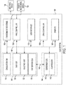
- FIGURE 1 illustrates an HVAC system 100.
- the HVAC system 100 is a networked HVAC system that is configured to condition air via, for example, heating, cooling, humidifying, or dehumidifying air.
- the HVAC system 100 can be a residential system or a commercial system such as, for example, a roof top system.
- the HVAC system 100 as illustrated in FIGURE 1 , includes various components; however, in other embodiments, the HVAC system 100 may include additional components that are not illustrated but typically included within HVAC systems.
- the HVAC system 100 includes a circulation fan 110, a gas heat 120, an electric heat 122 typically associated with the circulation fan 110, and a refrigerant evaporator coil 130, also typically associated with the circulation fan 110.
- the circulation fan 110, the gas heat 120, the electric heat 122, and the refrigerant evaporator coil 130 are collectively referred to as an "indoor unit” 148.
- the indoor unit 148 is located within, or in close proximity to, an enclosed space 101.
- Some HVAC systems are packaged in one chassis and conditioned air is moved to and from the enclosed space 101.
- the HVAC system 100 also includes a compressor 140 and an associated condenser coil 142, which are typically referred to as an "outdoor unit" 144.
- the compressor 140 may be, for example a fixed-speed compressor, a variable-speed compressor, a single-stage compressor, or a multistage compressor.
- the outdoor unit 144 is, for example, mounted on a roof of a building or at ground-level.
- the compressor 140 and the associated condenser coil 142 are connected to an associated evaporator coil 130 by a refrigerant line 146.
- the compressor 140 may be a compressor system including at least two compressors of the same or different capacities.
- the circulation fan 110 may be a single-speed blower or may, in various embodiments be configured to operate at different capacities (i.e ., variable motor speeds) to circulate air through the HVAC system 100, whereby the circulated air is conditioned and supplied to the enclosed space 101.
- the HVAC system 100 includes an HVAC controller 150 that is configured to control operation of the various components of the HVAC system 100 such as, for example, the circulation fan 110, the gas heat 120, the electric heat 122, and the compressor 140.
- the HVAC system 100 may be a zoned system.
- the HVAC system 100 includes a zone controller 180, dampers 185, and a plurality of environment sensors 160.
- the HVAC controller 150 cooperates with the zone controller 180 and the dampers 185 to regulate the environment of the enclosed space.
- the HVAC controller 150 may be an integrated controller or a distributed controller that directs operation of the HVAC system 100.
- the HVAC controller 150 includes an interface to receive, for example, thermostat calls, temperature setpoints, blower control signals, environmental conditions, and operating mode status for various zones of the HVAC system 100.
- the HVAC controller 150 also includes a processor and a memory to direct operation of the HVAC system 100 including, for example, a speed of the circulation fan 110.
- the plurality of environment sensors 160 is associated with the HVAC controller 150 and also optionally associated with a user interface 170.
- the user interface 170 provides additional functions such as, for example, operational, diagnostic, status message display, and a visual interface that allows at least one of an installer, a user, a support entity, and a service provider to perform actions with respect to the HVAC system 100.
- the user interface 170 is, for example, a thermostat of the HVAC system 100.
- the user interface 170 is associated with at least one sensor of the plurality of environment sensors 160 to determine the environmental condition information and communicate that information to the user.
- the user interface 170 may also include a display, buttons, a microphone, a speaker, or other components to communicate with the user. Additionally, the user interface 170 may include a processor and memory that is configured to receive user-determined parameters, and calculate operational parameters of the HVAC system 100 as disclosed herein.
- the HVAC system 100 is configured to communicate with a plurality of devices such as, for example, a monitoring device 156, a communication device 155, and the like.
- the monitoring device 156 is not part of the HVAC system 100.
- the monitoring device 156 is a server or computer of a third party such as, for example, a manufacturer, a support entity, a service provider, and the like.
- the monitoring device 156 is located at an office of, for example, the manufacturer, the support entity, the service provider, and the like.
- the communication device 155 is a non-HVAC device having a primary function that is not associated with HVAC systems.
- non-HVAC devices include mobile-computing devices that are configured to interact with the HVAC system 100 to monitor and modify at least some of the operating parameters of the HVAC system 100.
- Mobile computing devices may be, for example, a personal computer (e.g., desktop or laptop), a tablet computer, a mobile device (e.g., smart phone), and the like.
- the communication device 155 includes at least one processor, memory and a user interface, such as a display.
- the communication device 155 disclosed herein includes other components that are typically included in such devices including, for example, a power supply, a communications interface, and the like.
- the zone controller 180 is configured to manage movement of conditioned air to designated zones of the enclosed space 101.
- Each of the designated zones include at least one conditioning or demand unit such as, for example, the gas heat 120 and at least one user interface 170 such as, for example, the thermostat.
- the zone-controlled HVAC system 100 allows the user to independently control the temperature in the designated zones.
- the zone controller 180 operates electronic dampers 185 to control air flow to the zones of the enclosed space.
- a data bus 190 which in the illustrated embodiment is a serial bus, couples various components of the HVAC system 100 together such that data is communicated therebetween.
- the data bus 190 may include, for example, any combination of hardware, software embedded in a computer readable medium, or encoded logic incorporated in hardware or otherwise stored (e.g., firmware) to couple components of the HVAC system 100 to each other.
- the data bus 190 may include an Accelerated Graphics Port (AGP) or other graphics bus, a Controller Area Network (CAN) bus, a front-side bus (FSB), a HYPERTRANSPORT (HT) interconnect, an INFINIBAND interconnect, a low-pin-count (LPC) bus, a memory bus, a Micro Channel Architecture (MCA) bus, a Peripheral Component Interconnect (PCI) bus, a PCI-Express (PCI-X) bus, a serial advanced technology attachment (SATA) bus, a Video Electronics Standards Association local (VLB) bus, or any other suitable bus or a combination of two or more of these.
- AGP Accelerated Graphics Port
- CAN Controller Area Network
- FAB front-side bus
- HT HYPERTRANSPORT
- INFINIBAND interconnect INFINIBAND interconnect
- LPC low-pin-count
- MCA Micro Channel Architecture
- PCI Peripheral Component Interconnect
- PCI-X PC
- the data bus 190 may include any number, type, or configuration of data buses 90, where appropriate.
- one or more data buses 90 (which may each include an address bus and a data bus) may couple the HVAC controller 150 to other components of the HVAC system 100.
- connections between various components of the HVAC system 100 are wired.
- conventional cable and contacts may be used to couple the HVAC controller 150 to the various components.
- a wireless connection is employed to provide at least some of the connections between components of the HVAC system such as, for example, a connection between the HVAC controller 150 and the circulation fan 110 or the plurality of environment sensors 160.
- FIGURE 2 is a schematic diagram of the HVAC system 100.
- the HVAC system 100 may be arranged as, for example, a package HVAC system, a split HVAC system, or any other HVAC system arrangement.
- the HVAC system 100 includes the refrigerant evaporator coil 130, the condenser coil 142, the compressor 140, and a metering device 202.
- the metering device 202 is, for example, a thermostatic expansion valve or a throttling valve.
- the refrigerant evaporator coil 130 is fluidly coupled to the compressor 140 via a suction line 204.
- the compressor 140 is fluidly coupled to the condenser coil 142 via a discharge line 206.
- the condenser coil 142 is fluidly coupled to the metering device 202 via a liquid line 208.
- low-pressure, low-temperature refrigerant is circulated through the refrigerant evaporator coil 130.
- the refrigerant is initially in a liquid/vapor state.
- the refrigerant may be, for example, R-32 or R-452B; however, in other embodiments, other types of refrigerant could be utilized.
- Air from within the enclosed space 101, which is typically warmer than the refrigerant, is circulated around the refrigerant evaporator coil 130 by the circulation fan 110.
- the refrigerant begins to boil after absorbing heat from the air and changes state to a low-pressure, low-temperature, super-heated vapor refrigerant.
- Saturated vapor, saturated liquid, and saturated fluid refer to a thermodynamic state where a liquid and its vapor exist in approximate equilibrium with each other.
- Super-heated fluid and super-heated vapor refer to a thermodynamic state where a refrigerant is heated above a saturation temperature of the refrigerant.
- Sub-cooled fluid and sub-cooled liquid refers to a thermodynamic state where a refrigerant is cooled below the saturation temperature of the refrigerant.
- the low-pressure, low-temperature, super-heated vapor refrigerant is introduced into the compressor 140 via the suction line 204.
- the compressor 140 increases the pressure of the low-pressure, low-temperature, super-heated vapor refrigerant and, by operation of the ideal gas law, also increases the temperature of the low-pressure, low-temperature, super-heated vapor refrigerant to form a high-pressure, high-temperature, superheated vapor refrigerant.
- the high-pressure, high-temperature, superheated vapor refrigerant travels through the discharge line 206 and enters the condenser coil 142.
- Outside air is circulated around the condenser coil 142 by a condenser fan 210.
- the outside air is typically cooler than the high-pressure, high-temperature, superheated vapor refrigerant present in the condenser coil 142.
- heat is transferred from the high-pressure, high-temperature, superheated vapor refrigerant to the outside air.
- Removal of heat from the high-pressure, high-temperature, superheated vapor refrigerant causes the high-pressure, high-temperature, superheated vapor refrigerant to condense and change from a vapor state to a high-pressure, high-temperature, sub-cooled liquid state.
- the high-pressure, high-temperature, sub-cooled liquid refrigerant leaves the condenser coil 142 via the liquid line 208 and enters the metering device 202.
- the pressure of the high-pressure, high-temperature, sub-cooled liquid refrigerant is abruptly reduced.
- the metering device 202 is, for example, a thermostatic expansion valve
- the metering device 202 reduces the pressure of the high-pressure, high-temperature, sub-cooled liquid refrigerant by regulating an amount of refrigerant that travels to the refrigerant evaporator coil 130.
- Abrupt reduction of the pressure of the high-pressure, high-temperature, sub-cooled liquid refrigerant causes rapid evaporation of a portion of the high-pressure, high-temperature, sub-cooled liquid refrigerant, commonly known as flash evaporation.
- the flash evaporation lowers the temperature of the resulting liquid/vapor refrigerant mixture to a temperature lower than a temperature of the air in the enclosed space 101.
- the liquid/vapor refrigerant mixture leaves the metering device 202 and returns to the refrigerant evaporator coil 130.
- a metering orifice 250 is coupled to the suction line 204.
- the metering orifice 250 may be, for example, an orifice plate, a venturi device, or any other type of metering device.
- the metering orifice 250 may be, for example, a short-tube orifice having a tube length that is several times the tube diameter.
- the metering orifice 250 is fluidly coupled to a valve 252 such as, for example, a solenoid valve. During operation, the metering orifice 250 limits an amount of refrigerant that passes from the suction line 204 into the valve 252.
- the metering orifice 250 may be located at any point in the HVAC system 100 that will be a source of refrigerant vapor but not refrigerant liquid.
- the valve 252 is electrically connected to the HVAC controller 150.
- a first end 257 of a connecting tube 254 is coupled to the valve 252 and a mixing device 256 is coupled to a second end 258 of the connecting tube.
- the connecting tube 254 could be in the form of a small chamber and the mixing device 256 could be directly coupled to the valve 252.
- the mixing device 256 includes an output orifice 260 that is positioned proximate a refrigerant detector 262.
- the mixing device 256 and the refrigerant detector 262 are positioned proximate the circulation fan 110; however, in other embodiments, the mixing device 256 and the refrigerant detector 262 may be positioned in other locations where flammable refrigerant might accumulate.
- the HVAC system also includes a reversing valve 205 fluidly coupled to the compressor 140. When actuated, the reversing valve 205 reverses the flow of refrigerant through the condenser 142 and the evaporator 130 thereby allowing the HVAC system to be used for heating applications as well as cooling applications.
- FIGURE 3 is side-cross sectional view of the mixing device 256.
- An input orifice 264 of the mixing device 256 is coupled to the connecting tube 254. During operation the input orifice 264 receives intermittent flow of refrigerant via the valve 252 from the connecting tube 254.
- An air intake 266 is positioned proximate the input orifice 264. The air intake 266 is arranged generally perpendicular to the input orifice 264; however, in other embodiments, other arrangements could be utilized.
- a flow restriction 268 is positioned about an interior of the input orifice 264. The flow restriction 268 meters an amount of refrigerant and increases the velocity of refrigerant that passes through the mixing device 256.
- a body 270 of the mixing device 256 directs the air/refrigerant mixture towards the output orifice 260.
- the body includes a throttling portion 272 of a reduced interior cross-sectional area and a diffuser section 274 positioned downstream of the throttling portion 272 and having a gradually increasing interior cross-sectional area.
- the expanding/contracting shape of the mixing device 256 facilitates the creation of a uniform mixture of air and refrigerant.
- the relative sizes of the input orifice 264 and the air intake 266 allows the concentration of the refrigerant/air mixture to be set.
- the output orifice 260 is located at an end of the diffuser section 274.
- the refrigerant detector 262 has a factory-set alarm level that is appropriate for the refrigerant in use. To test the refrigerant detector 262 for sensitivity, the calibrated mixture of refrigerant and air is set to be slightly above the predetermined alarm level of the refrigerant detector 262. A successful test occurs when the refrigerant detector 262 alarms after exposure to a puff of refrigerant/air mixture with refrigerant concentration slightly above the alarm setpoint.
- the HVAC controller 150 measures a calibration interval and will attempt to calibrate the refrigerant detector 262 when the calibration interval has been measured.
- the calibration interval is, for example once every six months or once every year.
- the HVAC controller 150 directs the valve 252 to open for a first period of time such as, for example, 1 second.
- the refrigerant is typically at a pressure many times higher than atmospheric pressure. This pressure is used to induce the flow of air into the mixing device 256. A short burst of one or more seconds is adequate to provide the refrigerant detector 260 with a sample mixture.
- valve 252 When the valve 252 is opened an amount of refrigerant is metered by the metering orifice 250 to pass through the valve 252 and into the connecting tube 254.
- the amount of refrigerant released by the valve 252 does not contribute to a loss of performance of the HVAC system and is considered "de minimis" by EPA regulations. For example, it is estimated that approximately four grams of refrigerant is lost from an HVAC system each time service work is performed. Such refrigerant loss is considered acceptable by EPA standards. In comparison, approximately one-half a gram of refrigerant is sufficient to check the calibration of the refrigerant detector 262.
- the amount of refrigerant metered by the metering orifice 250 and released by the valve 252 is not sufficient to contribute to a loss of performance of the HVAC system 100.
- the refrigerant is mixed with air in the mixing device 256 to create an air/refrigerant mixture.
- the refrigerant/air mixture is approximately 4% refrigerant and approximately 96% air; however, in other embodiments, other mixture ratios could be utilized.
- the refrigerant content of the refrigerant/air mixture should be approximately 25% of the lower flammability threshold of the refrigerant.
- the air/refrigerant mixture is discharged from the output orifice 260 towards the refrigerant detector 262.
- the HVAC controller 150 detects if the refrigerant detector 262 triggers an alarm in the presence of the refrigerant/air mixture.
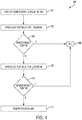
- FIGURE 4 is a flow diagram of a process 400 for calibrating a refrigerant sensor.
- the compressor 140 and the circulation fan 110 are turned off.
- the valve 252 opens for the first pre-determined time period such as, for example, 1 second.
- the HVAC controller 150 determines if the refrigerant detector 262 has alarmed. If the refrigerant detector 262 alarms, the process 400 ends at block 406. If the refrigerant detector 262 has not alarmed, the process 400 proceeds to block 408 where the valve 252 is again opened for a second predetermined period of time such as, for example, 1 second.
- the second pre-determined period of time may be equal to or different than the first pre-determined period of time.
- the HVAC controller 150 determines if the refrigerant detector 262 has alarmed. If the refrigerant detector 262 alarms, the process 400 ends at block 406. If the refrigerant detector 262 has not alarmed, the process 400 proceeds to block 412 where a refrigerant detector failure alert is generated.
- the HVAC system 100 self-calibrates the refrigerant detector 262, utilizing refrigerant already present in the HVAC system 100, to a specific amount of refrigerant thereby eliminating a need for maintenance to be performed by a service technician.
- the refrigerant discharged during testing of the refrigerant detector 262 is environmentally safe and does not contribute to a loss of performance of the HVAC system 100.
- acts, events, or functions of any of the algorithms, methods, or processes described herein can be performed in a different sequence, can be added, merged, or left out altogether ( e.g ., not all described acts or events are necessary for the practice of the algorithms, methods, or processes).
- acts or events can be performed concurrently, e.g ., through multi-threaded processing, interrupt processing, or multiple processors or processor cores or on other parallel architectures, rather than sequentially.
- certain computer-implemented tasks are described as being performed by a particular entity, other embodiments are possible in which these tasks are performed by a different entity.
Landscapes
- Engineering & Computer Science (AREA)
- Physics & Mathematics (AREA)
- Mechanical Engineering (AREA)
- Thermal Sciences (AREA)
- General Engineering & Computer Science (AREA)
- General Physics & Mathematics (AREA)
- Air Conditioning Control Device (AREA)
Applications Claiming Priority (1)
| Application Number | Priority Date | Filing Date | Title |
|---|---|---|---|
| US15/848,637 US10760838B2 (en) | 2017-12-20 | 2017-12-20 | Method and apparatus for refrigerant detector calibration confirmation |
Publications (2)
| Publication Number | Publication Date |
|---|---|
| EP3517856A1 true EP3517856A1 (fr) | 2019-07-31 |
| EP3517856B1 EP3517856B1 (fr) | 2021-01-13 |
Family
ID=64267678
Family Applications (1)
| Application Number | Title | Priority Date | Filing Date |
|---|---|---|---|
| EP18205206.8A Active EP3517856B1 (fr) | 2017-12-20 | 2018-11-08 | Procédé et appareil de confirmation d'étalonnage d'un détecteur de fluide frigorigène |
Country Status (3)
| Country | Link |
|---|---|
| US (2) | US10760838B2 (fr) |
| EP (1) | EP3517856B1 (fr) |
| CA (1) | CA3026503C (fr) |
Families Citing this family (7)
| Publication number | Priority date | Publication date | Assignee | Title |
|---|---|---|---|---|
| US11231198B2 (en) | 2019-09-05 | 2022-01-25 | Trane International Inc. | Systems and methods for refrigerant leak detection in a climate control system |
| CN111102680A (zh) * | 2019-12-10 | 2020-05-05 | 宁波奥克斯电气股份有限公司 | 一种冷媒量自动校准装置和校准方法 |
| US20210310708A1 (en) * | 2020-04-01 | 2021-10-07 | Philip Brash | Refrigerant Identification Assembly |
| US11609032B2 (en) * | 2020-10-22 | 2023-03-21 | Emerson Climate Technologies, Inc. | Refrigerant leak sensor measurement adjustment systems and methods |
| EP4148358A1 (fr) * | 2021-09-08 | 2023-03-15 | Carrier Corporation | Meuble présentoir réfrigéré |
| US12487008B2 (en) | 2022-01-14 | 2025-12-02 | Trane International Inc. | Method of commissioning an HVAC system |
| US12117191B2 (en) | 2022-06-24 | 2024-10-15 | Trane International Inc. | Climate control system with improved leak detector |
Citations (4)
| Publication number | Priority date | Publication date | Assignee | Title |
|---|---|---|---|---|
| EP0142424A2 (fr) * | 1983-11-10 | 1985-05-22 | Bertin & Cie | Ejecteur-mélangeur à effet de trompe à section variable |
| US20090107157A1 (en) * | 2007-10-25 | 2009-04-30 | Serge Dube | Refrigerant leak-detection systems |
| WO2011147958A1 (fr) * | 2010-05-28 | 2011-12-01 | Gea Brewery Systems Gmbh Huppmann Tuchenhagen | Procédé permettant d'accélérer la fermentation, et dispositif de mélange du contenu d'une cuve |
| US20120090383A1 (en) * | 2010-10-14 | 2012-04-19 | Audra Lopez | System and method for detecting a refrigerant leak and chemicals produced as a result of heating of the refrigerant |
Family Cites Families (25)
| Publication number | Priority date | Publication date | Assignee | Title |
|---|---|---|---|---|
| US4476688A (en) * | 1983-02-18 | 1984-10-16 | Goddard Lawrence A | Refrigerant recovery and purification system |
| US4726195A (en) * | 1986-08-22 | 1988-02-23 | Air Products And Chemicals, Inc. | Cryogenic forced convection refrigerating system |
| US5176187A (en) * | 1989-06-27 | 1993-01-05 | Ashland Oil, Inc. | Flexible gas salvage containers and process for use |
| US5024061A (en) * | 1989-12-12 | 1991-06-18 | Terrestrial Engineering Corporation | Recovery processing and storage unit |
| US5122341A (en) * | 1990-10-17 | 1992-06-16 | Carrier Corporation | Device for gas contaminant tester training |
| JP2004116875A (ja) * | 2002-09-25 | 2004-04-15 | Horiba Ltd | 冷媒の追加充填量算出装置および冷媒の追加充填量算出方法 |
| US7104075B2 (en) * | 2004-07-19 | 2006-09-12 | Snap-On Incorporated | Arrangement and method for controlling the discharge of carbon dioxide for air conditioning systems |
| US7472557B2 (en) * | 2004-12-27 | 2009-01-06 | Carrier Corporation | Automatic refrigerant charging apparatus |
| JP4490362B2 (ja) * | 2005-11-10 | 2010-06-23 | 三菱電機株式会社 | 可燃性冷媒の処理装置 |
| US7866172B2 (en) * | 2006-07-14 | 2011-01-11 | Trane International Inc. | System and method for controlling working fluid charge in a vapor compression air conditioning system |
| US7814757B2 (en) * | 2006-09-12 | 2010-10-19 | Delphi Technologies, Inc. | Operating algorithm for refrigerant safety system |
| JP4225357B2 (ja) * | 2007-04-13 | 2009-02-18 | ダイキン工業株式会社 | 冷媒充填装置、冷凍装置及び冷媒充填方法 |
| JP5182159B2 (ja) * | 2009-03-06 | 2013-04-10 | 株式会社デンソー | エジェクタ方式の減圧装置およびこれを備えた冷凍サイクル |
| JP5413393B2 (ja) * | 2011-03-28 | 2014-02-12 | 株式会社デンソー | 冷媒分配器および冷凍サイクル |
| US20130255294A1 (en) * | 2012-03-28 | 2013-10-03 | Trane International Inc. | Charge Port For Microchannel Heat Exchanger Systems |
| JP5831423B2 (ja) * | 2012-10-08 | 2015-12-09 | 株式会社デンソー | 冷凍サイクル装置 |
| US20160025393A1 (en) * | 2013-03-15 | 2016-01-28 | Armstrong International, Inc. | Refrigeration Purger Monitor |
| CA2914848C (fr) * | 2013-06-19 | 2019-03-19 | Bechtel Hydrocarbon Technology Solutions, Inc. | Systemes et procedes d'augmentation de capcite de liquefaction de gaz naturel |
| JP6003844B2 (ja) * | 2013-08-09 | 2016-10-05 | 株式会社デンソー | エジェクタ |
| JP6384374B2 (ja) * | 2015-03-23 | 2018-09-05 | 株式会社デンソー | エジェクタ式冷凍サイクル |
| KR102380053B1 (ko) * | 2015-10-16 | 2022-03-29 | 삼성전자주식회사 | 공기조화장치, 이에 사용되는 이젝터, 및 공기조화장치의 제어방법 |
| JP6644620B2 (ja) * | 2016-03-31 | 2020-02-12 | 三菱重工サーマルシステムズ株式会社 | 抽気装置およびこれを備えた冷凍機ならびに抽気装置の制御方法 |
| JP2017219262A (ja) * | 2016-06-08 | 2017-12-14 | 株式会社デンソー | エジェクタ式冷凍サイクル装置 |
| WO2018073853A1 (fr) * | 2016-10-17 | 2018-04-26 | 三菱電機株式会社 | Unité intérieure pour équipement d'utilisation de pompe à chaleur et équipement d'utilisation de pompe à chaleur équipé de celle-ci |
| US10514176B2 (en) * | 2017-12-01 | 2019-12-24 | Johnson Controls Technology Company | Systems and methods for refrigerant leak management |
-
2017
- 2017-12-20 US US15/848,637 patent/US10760838B2/en active Active
-
2018
- 2018-11-08 EP EP18205206.8A patent/EP3517856B1/fr active Active
- 2018-12-05 CA CA3026503A patent/CA3026503C/fr active Active
-
2020
- 2020-07-28 US US16/940,443 patent/US11378313B2/en active Active
Patent Citations (4)
| Publication number | Priority date | Publication date | Assignee | Title |
|---|---|---|---|---|
| EP0142424A2 (fr) * | 1983-11-10 | 1985-05-22 | Bertin & Cie | Ejecteur-mélangeur à effet de trompe à section variable |
| US20090107157A1 (en) * | 2007-10-25 | 2009-04-30 | Serge Dube | Refrigerant leak-detection systems |
| WO2011147958A1 (fr) * | 2010-05-28 | 2011-12-01 | Gea Brewery Systems Gmbh Huppmann Tuchenhagen | Procédé permettant d'accélérer la fermentation, et dispositif de mélange du contenu d'une cuve |
| US20120090383A1 (en) * | 2010-10-14 | 2012-04-19 | Audra Lopez | System and method for detecting a refrigerant leak and chemicals produced as a result of heating of the refrigerant |
Also Published As
| Publication number | Publication date |
|---|---|
| US11378313B2 (en) | 2022-07-05 |
| US20190186798A1 (en) | 2019-06-20 |
| EP3517856B1 (fr) | 2021-01-13 |
| US10760838B2 (en) | 2020-09-01 |
| US20200355420A1 (en) | 2020-11-12 |
| CA3026503A1 (fr) | 2019-06-20 |
| CA3026503C (fr) | 2024-04-09 |
Similar Documents
| Publication | Publication Date | Title |
|---|---|---|
| US11378313B2 (en) | Method and apparatus for refrigerant detector calibration confirmation | |
| US11609046B2 (en) | Detecting loss of charge in HVAC systems | |
| US11644206B2 (en) | HVAC system prognostics and diagnostics based on temperature rise or drop | |
| US20220333806A1 (en) | Dual temperature sensor arrangement to detect refrigerant leak | |
| US11719457B2 (en) | HVAC system and method for determining a temperature offset between a discharged air temperature and an indoor temperature | |
| WO2019234902A1 (fr) | Unité intérieure de dispositif de conditionnement d'air et dispositif de conditionnement d'air | |
| US20250067453A1 (en) | System and method for providing cooling during refrigerant leak | |
| US20250035356A1 (en) | Refrigerant leak mitigation using isolation valves | |
| US12590722B2 (en) | System and method for detecting a refrigerant leak in an HVAC system operating in an idle mode | |
| US12066229B2 (en) | Sensor validation | |
| US12000631B1 (en) | Systems and methods for refrigerant leak mitigation | |
| US20210088263A1 (en) | Method and system for charge determination | |
| US12298049B2 (en) | System and method for identifying a refrigerant leak in multiple refrigeration circuits with one or more compressors | |
| US11796201B2 (en) | HVAC sensor validation while HVAC system is off | |
| WO2024176406A1 (fr) | Dispositif de commande pour climatiseur |
Legal Events
| Date | Code | Title | Description |
|---|---|---|---|
| PUAI | Public reference made under article 153(3) epc to a published international application that has entered the european phase |
Free format text: ORIGINAL CODE: 0009012 |
|
| STAA | Information on the status of an ep patent application or granted ep patent |
Free format text: STATUS: THE APPLICATION HAS BEEN PUBLISHED |
|
| AK | Designated contracting states |
Kind code of ref document: A1 Designated state(s): AL AT BE BG CH CY CZ DE DK EE ES FI FR GB GR HR HU IE IS IT LI LT LU LV MC MK MT NL NO PL PT RO RS SE SI SK SM TR |
|
| AX | Request for extension of the european patent |
Extension state: BA ME |
|
| STAA | Information on the status of an ep patent application or granted ep patent |
Free format text: STATUS: REQUEST FOR EXAMINATION WAS MADE |
|
| 17P | Request for examination filed |
Effective date: 20200117 |
|
| RBV | Designated contracting states (corrected) |
Designated state(s): AL AT BE BG CH CY CZ DE DK EE ES FI FR GB GR HR HU IE IS IT LI LT LU LV MC MK MT NL NO PL PT RO RS SE SI SK SM TR |
|
| GRAP | Despatch of communication of intention to grant a patent |
Free format text: ORIGINAL CODE: EPIDOSNIGR1 |
|
| STAA | Information on the status of an ep patent application or granted ep patent |
Free format text: STATUS: GRANT OF PATENT IS INTENDED |
|
| INTG | Intention to grant announced |
Effective date: 20200311 |
|
| GRAS | Grant fee paid |
Free format text: ORIGINAL CODE: EPIDOSNIGR3 |
|
| GRAJ | Information related to disapproval of communication of intention to grant by the applicant or resumption of examination proceedings by the epo deleted |
Free format text: ORIGINAL CODE: EPIDOSDIGR1 |
|
| GRAP | Despatch of communication of intention to grant a patent |
Free format text: ORIGINAL CODE: EPIDOSNIGR1 |
|
| INTG | Intention to grant announced |
Effective date: 20200714 |
|
| GRAS | Grant fee paid |
Free format text: ORIGINAL CODE: EPIDOSNIGR3 |
|
| GRAA | (expected) grant |
Free format text: ORIGINAL CODE: 0009210 |
|
| STAA | Information on the status of an ep patent application or granted ep patent |
Free format text: STATUS: THE PATENT HAS BEEN GRANTED |
|
| AK | Designated contracting states |
Kind code of ref document: B1 Designated state(s): AL AT BE BG CH CY CZ DE DK EE ES FI FR GB GR HR HU IE IS IT LI LT LU LV MC MK MT NL NO PL PT RO RS SE SI SK SM TR |
|
| REG | Reference to a national code |
Ref country code: GB Ref legal event code: FG4D |
|
| REG | Reference to a national code |
Ref country code: CH Ref legal event code: EP |
|
| REG | Reference to a national code |
Ref country code: IE Ref legal event code: FG4D |
|
| REG | Reference to a national code |
Ref country code: DE Ref legal event code: R096 Ref document number: 602018011802 Country of ref document: DE |
|
| REG | Reference to a national code |
Ref country code: AT Ref legal event code: REF Ref document number: 1354870 Country of ref document: AT Kind code of ref document: T Effective date: 20210215 |
|
| REG | Reference to a national code |
Ref country code: AT Ref legal event code: MK05 Ref document number: 1354870 Country of ref document: AT Kind code of ref document: T Effective date: 20210113 |
|
| REG | Reference to a national code |
Ref country code: NL Ref legal event code: MP Effective date: 20210113 |
|
| REG | Reference to a national code |
Ref country code: LT Ref legal event code: MG9D |
|
| PG25 | Lapsed in a contracting state [announced via postgrant information from national office to epo] |
Ref country code: BG Free format text: LAPSE BECAUSE OF FAILURE TO SUBMIT A TRANSLATION OF THE DESCRIPTION OR TO PAY THE FEE WITHIN THE PRESCRIBED TIME-LIMIT Effective date: 20210413 Ref country code: GR Free format text: LAPSE BECAUSE OF FAILURE TO SUBMIT A TRANSLATION OF THE DESCRIPTION OR TO PAY THE FEE WITHIN THE PRESCRIBED TIME-LIMIT Effective date: 20210414 Ref country code: FI Free format text: LAPSE BECAUSE OF FAILURE TO SUBMIT A TRANSLATION OF THE DESCRIPTION OR TO PAY THE FEE WITHIN THE PRESCRIBED TIME-LIMIT Effective date: 20210113 Ref country code: HR Free format text: LAPSE BECAUSE OF FAILURE TO SUBMIT A TRANSLATION OF THE DESCRIPTION OR TO PAY THE FEE WITHIN THE PRESCRIBED TIME-LIMIT Effective date: 20210113 Ref country code: NO Free format text: LAPSE BECAUSE OF FAILURE TO SUBMIT A TRANSLATION OF THE DESCRIPTION OR TO PAY THE FEE WITHIN THE PRESCRIBED TIME-LIMIT Effective date: 20210413 Ref country code: PT Free format text: LAPSE BECAUSE OF FAILURE TO SUBMIT A TRANSLATION OF THE DESCRIPTION OR TO PAY THE FEE WITHIN THE PRESCRIBED TIME-LIMIT Effective date: 20210513 Ref country code: LT Free format text: LAPSE BECAUSE OF FAILURE TO SUBMIT A TRANSLATION OF THE DESCRIPTION OR TO PAY THE FEE WITHIN THE PRESCRIBED TIME-LIMIT Effective date: 20210113 |
|
| PG25 | Lapsed in a contracting state [announced via postgrant information from national office to epo] |
Ref country code: SE Free format text: LAPSE BECAUSE OF FAILURE TO SUBMIT A TRANSLATION OF THE DESCRIPTION OR TO PAY THE FEE WITHIN THE PRESCRIBED TIME-LIMIT Effective date: 20210113 Ref country code: AT Free format text: LAPSE BECAUSE OF FAILURE TO SUBMIT A TRANSLATION OF THE DESCRIPTION OR TO PAY THE FEE WITHIN THE PRESCRIBED TIME-LIMIT Effective date: 20210113 Ref country code: LV Free format text: LAPSE BECAUSE OF FAILURE TO SUBMIT A TRANSLATION OF THE DESCRIPTION OR TO PAY THE FEE WITHIN THE PRESCRIBED TIME-LIMIT Effective date: 20210113 Ref country code: RS Free format text: LAPSE BECAUSE OF FAILURE TO SUBMIT A TRANSLATION OF THE DESCRIPTION OR TO PAY THE FEE WITHIN THE PRESCRIBED TIME-LIMIT Effective date: 20210113 Ref country code: PL Free format text: LAPSE BECAUSE OF FAILURE TO SUBMIT A TRANSLATION OF THE DESCRIPTION OR TO PAY THE FEE WITHIN THE PRESCRIBED TIME-LIMIT Effective date: 20210113 |
|
| PG25 | Lapsed in a contracting state [announced via postgrant information from national office to epo] |
Ref country code: IS Free format text: LAPSE BECAUSE OF FAILURE TO SUBMIT A TRANSLATION OF THE DESCRIPTION OR TO PAY THE FEE WITHIN THE PRESCRIBED TIME-LIMIT Effective date: 20210513 |
|
| REG | Reference to a national code |
Ref country code: DE Ref legal event code: R097 Ref document number: 602018011802 Country of ref document: DE |
|
| PG25 | Lapsed in a contracting state [announced via postgrant information from national office to epo] |
Ref country code: SM Free format text: LAPSE BECAUSE OF FAILURE TO SUBMIT A TRANSLATION OF THE DESCRIPTION OR TO PAY THE FEE WITHIN THE PRESCRIBED TIME-LIMIT Effective date: 20210113 Ref country code: EE Free format text: LAPSE BECAUSE OF FAILURE TO SUBMIT A TRANSLATION OF THE DESCRIPTION OR TO PAY THE FEE WITHIN THE PRESCRIBED TIME-LIMIT Effective date: 20210113 Ref country code: CZ Free format text: LAPSE BECAUSE OF FAILURE TO SUBMIT A TRANSLATION OF THE DESCRIPTION OR TO PAY THE FEE WITHIN THE PRESCRIBED TIME-LIMIT Effective date: 20210113 |
|
| PLBE | No opposition filed within time limit |
Free format text: ORIGINAL CODE: 0009261 |
|
| STAA | Information on the status of an ep patent application or granted ep patent |
Free format text: STATUS: NO OPPOSITION FILED WITHIN TIME LIMIT |
|
| PG25 | Lapsed in a contracting state [announced via postgrant information from national office to epo] |
Ref country code: SK Free format text: LAPSE BECAUSE OF FAILURE TO SUBMIT A TRANSLATION OF THE DESCRIPTION OR TO PAY THE FEE WITHIN THE PRESCRIBED TIME-LIMIT Effective date: 20210113 Ref country code: RO Free format text: LAPSE BECAUSE OF FAILURE TO SUBMIT A TRANSLATION OF THE DESCRIPTION OR TO PAY THE FEE WITHIN THE PRESCRIBED TIME-LIMIT Effective date: 20210113 Ref country code: DK Free format text: LAPSE BECAUSE OF FAILURE TO SUBMIT A TRANSLATION OF THE DESCRIPTION OR TO PAY THE FEE WITHIN THE PRESCRIBED TIME-LIMIT Effective date: 20210113 |
|
| 26N | No opposition filed |
Effective date: 20211014 |
|
| PG25 | Lapsed in a contracting state [announced via postgrant information from national office to epo] |
Ref country code: ES Free format text: LAPSE BECAUSE OF FAILURE TO SUBMIT A TRANSLATION OF THE DESCRIPTION OR TO PAY THE FEE WITHIN THE PRESCRIBED TIME-LIMIT Effective date: 20210113 Ref country code: AL Free format text: LAPSE BECAUSE OF FAILURE TO SUBMIT A TRANSLATION OF THE DESCRIPTION OR TO PAY THE FEE WITHIN THE PRESCRIBED TIME-LIMIT Effective date: 20210113 |
|
| PG25 | Lapsed in a contracting state [announced via postgrant information from national office to epo] |
Ref country code: SI Free format text: LAPSE BECAUSE OF FAILURE TO SUBMIT A TRANSLATION OF THE DESCRIPTION OR TO PAY THE FEE WITHIN THE PRESCRIBED TIME-LIMIT Effective date: 20210113 |
|
| PG25 | Lapsed in a contracting state [announced via postgrant information from national office to epo] |
Ref country code: IT Free format text: LAPSE BECAUSE OF FAILURE TO SUBMIT A TRANSLATION OF THE DESCRIPTION OR TO PAY THE FEE WITHIN THE PRESCRIBED TIME-LIMIT Effective date: 20210113 |
|
| PG25 | Lapsed in a contracting state [announced via postgrant information from national office to epo] |
Ref country code: IS Free format text: LAPSE BECAUSE OF FAILURE TO SUBMIT A TRANSLATION OF THE DESCRIPTION OR TO PAY THE FEE WITHIN THE PRESCRIBED TIME-LIMIT Effective date: 20210513 |
|
| PG25 | Lapsed in a contracting state [announced via postgrant information from national office to epo] |
Ref country code: MC Free format text: LAPSE BECAUSE OF FAILURE TO SUBMIT A TRANSLATION OF THE DESCRIPTION OR TO PAY THE FEE WITHIN THE PRESCRIBED TIME-LIMIT Effective date: 20210113 |
|
| REG | Reference to a national code |
Ref country code: CH Ref legal event code: PL |
|
| PG25 | Lapsed in a contracting state [announced via postgrant information from national office to epo] |
Ref country code: LU Free format text: LAPSE BECAUSE OF NON-PAYMENT OF DUE FEES Effective date: 20211108 Ref country code: BE Free format text: LAPSE BECAUSE OF NON-PAYMENT OF DUE FEES Effective date: 20211130 |
|
| REG | Reference to a national code |
Ref country code: BE Ref legal event code: MM Effective date: 20211130 |
|
| PG25 | Lapsed in a contracting state [announced via postgrant information from national office to epo] |
Ref country code: IE Free format text: LAPSE BECAUSE OF NON-PAYMENT OF DUE FEES Effective date: 20211108 |
|
| PG25 | Lapsed in a contracting state [announced via postgrant information from national office to epo] |
Ref country code: NL Free format text: LAPSE BECAUSE OF NON-PAYMENT OF DUE FEES Effective date: 20210113 Ref country code: CY Free format text: LAPSE BECAUSE OF FAILURE TO SUBMIT A TRANSLATION OF THE DESCRIPTION OR TO PAY THE FEE WITHIN THE PRESCRIBED TIME-LIMIT Effective date: 20210113 |
|
| PG25 | Lapsed in a contracting state [announced via postgrant information from national office to epo] |
Ref country code: LI Free format text: LAPSE BECAUSE OF NON-PAYMENT OF DUE FEES Effective date: 20220630 Ref country code: HU Free format text: LAPSE BECAUSE OF FAILURE TO SUBMIT A TRANSLATION OF THE DESCRIPTION OR TO PAY THE FEE WITHIN THE PRESCRIBED TIME-LIMIT; INVALID AB INITIO Effective date: 20181108 Ref country code: CH Free format text: LAPSE BECAUSE OF NON-PAYMENT OF DUE FEES Effective date: 20220630 |
|
| PG25 | Lapsed in a contracting state [announced via postgrant information from national office to epo] |
Ref country code: MK Free format text: LAPSE BECAUSE OF FAILURE TO SUBMIT A TRANSLATION OF THE DESCRIPTION OR TO PAY THE FEE WITHIN THE PRESCRIBED TIME-LIMIT Effective date: 20210113 |
|
| PG25 | Lapsed in a contracting state [announced via postgrant information from national office to epo] |
Ref country code: TR Free format text: LAPSE BECAUSE OF FAILURE TO SUBMIT A TRANSLATION OF THE DESCRIPTION OR TO PAY THE FEE WITHIN THE PRESCRIBED TIME-LIMIT Effective date: 20210113 |
|
| PG25 | Lapsed in a contracting state [announced via postgrant information from national office to epo] |
Ref country code: MT Free format text: LAPSE BECAUSE OF FAILURE TO SUBMIT A TRANSLATION OF THE DESCRIPTION OR TO PAY THE FEE WITHIN THE PRESCRIBED TIME-LIMIT Effective date: 20210113 |
|
| PGFP | Annual fee paid to national office [announced via postgrant information from national office to epo] |
Ref country code: DE Payment date: 20251128 Year of fee payment: 8 |
|
| PGFP | Annual fee paid to national office [announced via postgrant information from national office to epo] |
Ref country code: GB Payment date: 20251127 Year of fee payment: 8 |
|
| PGFP | Annual fee paid to national office [announced via postgrant information from national office to epo] |
Ref country code: FR Payment date: 20251125 Year of fee payment: 8 |