EP3517859A1 - Appareil de cycle de réfrigération - Google Patents
Appareil de cycle de réfrigération Download PDFInfo
- Publication number
- EP3517859A1 EP3517859A1 EP18189439.5A EP18189439A EP3517859A1 EP 3517859 A1 EP3517859 A1 EP 3517859A1 EP 18189439 A EP18189439 A EP 18189439A EP 3517859 A1 EP3517859 A1 EP 3517859A1
- Authority
- EP
- European Patent Office
- Prior art keywords
- refrigerant
- gas
- liquid
- heat exchanger
- pipe
- Prior art date
- Legal status (The legal status is an assumption and is not a legal conclusion. Google has not performed a legal analysis and makes no representation as to the accuracy of the status listed.)
- Granted
Links
Images





Classifications
-
- F—MECHANICAL ENGINEERING; LIGHTING; HEATING; WEAPONS; BLASTING
- F25—REFRIGERATION OR COOLING; COMBINED HEATING AND REFRIGERATION SYSTEMS; HEAT PUMP SYSTEMS; MANUFACTURE OR STORAGE OF ICE; LIQUEFACTION SOLIDIFICATION OF GASES
- F25B—REFRIGERATION MACHINES, PLANTS OR SYSTEMS; COMBINED HEATING AND REFRIGERATION SYSTEMS; HEAT PUMP SYSTEMS
- F25B1/00—Compression machines, plants or systems with non-reversible cycle
- F25B1/10—Compression machines, plants or systems with non-reversible cycle with multi-stage compression
-
- F—MECHANICAL ENGINEERING; LIGHTING; HEATING; WEAPONS; BLASTING
- F25—REFRIGERATION OR COOLING; COMBINED HEATING AND REFRIGERATION SYSTEMS; HEAT PUMP SYSTEMS; MANUFACTURE OR STORAGE OF ICE; LIQUEFACTION SOLIDIFICATION OF GASES
- F25B—REFRIGERATION MACHINES, PLANTS OR SYSTEMS; COMBINED HEATING AND REFRIGERATION SYSTEMS; HEAT PUMP SYSTEMS
- F25B41/00—Fluid-circulation arrangements
- F25B41/20—Disposition of valves, e.g. of on-off valves or flow control valves
-
- F—MECHANICAL ENGINEERING; LIGHTING; HEATING; WEAPONS; BLASTING
- F25—REFRIGERATION OR COOLING; COMBINED HEATING AND REFRIGERATION SYSTEMS; HEAT PUMP SYSTEMS; MANUFACTURE OR STORAGE OF ICE; LIQUEFACTION SOLIDIFICATION OF GASES
- F25B—REFRIGERATION MACHINES, PLANTS OR SYSTEMS; COMBINED HEATING AND REFRIGERATION SYSTEMS; HEAT PUMP SYSTEMS
- F25B2400/00—Component parts or details not otherwise provided for in this subclass
- F25B2400/04—Refrigeration circuit bypassing means
- F25B2400/0409—Refrigeration circuit bypassing means for evaporators
-
- F—MECHANICAL ENGINEERING; LIGHTING; HEATING; WEAPONS; BLASTING
- F25—REFRIGERATION OR COOLING; COMBINED HEATING AND REFRIGERATION SYSTEMS; HEAT PUMP SYSTEMS; MANUFACTURE OR STORAGE OF ICE; LIQUEFACTION SOLIDIFICATION OF GASES
- F25B—REFRIGERATION MACHINES, PLANTS OR SYSTEMS; COMBINED HEATING AND REFRIGERATION SYSTEMS; HEAT PUMP SYSTEMS
- F25B2400/00—Component parts or details not otherwise provided for in this subclass
- F25B2400/04—Refrigeration circuit bypassing means
- F25B2400/0417—Refrigeration circuit bypassing means for subcoolers
-
- F—MECHANICAL ENGINEERING; LIGHTING; HEATING; WEAPONS; BLASTING
- F25—REFRIGERATION OR COOLING; COMBINED HEATING AND REFRIGERATION SYSTEMS; HEAT PUMP SYSTEMS; MANUFACTURE OR STORAGE OF ICE; LIQUEFACTION SOLIDIFICATION OF GASES
- F25B—REFRIGERATION MACHINES, PLANTS OR SYSTEMS; COMBINED HEATING AND REFRIGERATION SYSTEMS; HEAT PUMP SYSTEMS
- F25B2400/00—Component parts or details not otherwise provided for in this subclass
- F25B2400/13—Economisers
-
- F—MECHANICAL ENGINEERING; LIGHTING; HEATING; WEAPONS; BLASTING
- F25—REFRIGERATION OR COOLING; COMBINED HEATING AND REFRIGERATION SYSTEMS; HEAT PUMP SYSTEMS; MANUFACTURE OR STORAGE OF ICE; LIQUEFACTION SOLIDIFICATION OF GASES
- F25B—REFRIGERATION MACHINES, PLANTS OR SYSTEMS; COMBINED HEATING AND REFRIGERATION SYSTEMS; HEAT PUMP SYSTEMS
- F25B2400/00—Component parts or details not otherwise provided for in this subclass
- F25B2400/23—Separators
Definitions
- the present invention relates to a refrigeration cycle apparatus comprising an indoor unit and a compressor, wherein the compressor includes a mechanism for injecting an intermediate pressure refrigerant in a process of compressing and discharging the refrigerant sucked into the compressor.
- an intermediate pressure refrigerant piping section includes a gas-liquid separator and an injection pipe
- the injection pipe communicates with an injection hole of a compressor
- a gas bypass pipe connects the gas-liquid separator and the injection pipe
- FIG. 7 illustrates a configuration view of the refrigeration cycle apparatus disclosed in Japanese Patent Laid-Open No. 2011-52883 .
- an intermediate pressure refrigerant piping section is formed by a throttling device 26a, a throttling device 26b, and a throttling device 27.
- the configuration includes an injection pipe 29; a flow control device 30 which controls the refrigerant flow rate flowing in the injection pipe 29; a gas-liquid separator 31 disposed in the intermediate pressure refrigerant piping section; a gas bypass pipe 32 which connects the injection pipe 29 and the gas-liquid separator 31; and an open/close valve 33 which controls the refrigerant flow rate flowing in the gas bypass pipe 32, wherein the flow control device 30 and the open/close valve 33 are configured to open during operation of the compressor 23.
- this configuration can be expected to have effects such that during heating operation of the indoor unit, gas phase refrigerant flows in the gas bypass pipe 32 through the open/close valve 33 and enters an injection hole of the compressor 23, thereby increasing the operation efficiency of the refrigeration cycle apparatus, and refrigerant in a gas-liquid two-phase state flows in the injection pipe 29 through the flow control device 30 and enters the injection hole of the compressor 23, thereby suppressing an excessive increase in the temperature of the refrigerant discharged from the compressor 23.
- the refrigerant flowing in the injection pipe during heating operation of the indoor unit is in a gas-liquid two-phase state, and there is a small pressure difference between a joining portion of the injection pipe with the gas bypass pipe and a branch portion of the injection pipe.
- this configuration involves a problem in that low outside air temperature and the resultant increased compression ratio increases the temperature of the refrigerant discharged from the compressor, and thus even if the ratio of the liquid phase refrigerant having the effect of reducing temperature should be increased, only the gas phase refrigerant blows through the injection pipe, leading to a stagnant flow of the liquid phase refrigerant in the injection pipe, preventing the liquid phase refrigerant having the effect of reducing temperature from being supplied to the compressor, resulting in an excessive increase in temperature of the refrigerant discharged from the compressor.
- the performance of the refrigeration cycle apparatus is reduced by a reduction in motor efficiency due to an excessive increase in temperature of the motor winding and an increase in friction loss of the sliding portion due to reduced lubrication performance caused by deteriorated refrigerating machine oil.
- the present invention has been made to solve the above problem, and an object of the present invention is to provide a refrigeration cycle apparatus capable of supplying a sufficient amount of liquid phase refrigerant flowing into a compressor when the temperature of the refrigerant discharged from the compressor is increased during heating operation of an indoor unit.
- the refrigeration cycle apparatus of the present invention provides a refrigeration cycle apparatus including a compressor, an indoor heat exchanger, a first pressure regulating device, a second pressure regulating device, an outdoor heat exchanger, and an injection pipe, wherein the compressor, the indoor heat exchanger, the first pressure regulating device, the second pressure regulating device, and the outdoor heat exchanger are connected in order; and a first branch portion disposed in an intermediate pressure refrigerant pipe connecting the first pressure regulating device and the second pressure regulating device is connected to a compression unit of a compressor by an injection pipe, the refrigeration cycle apparatus comprising: a gas-liquid separator disposed between the first pressure regulating device and the second pressure regulating device; a gas bypass pipe disposed to connect the gas-liquid separator and the injection pipe and to flow gas refrigerant separated by the gas-liquid separator; and a flow control device disposed between the first branch portion and a joining portion where the injection pipe joins the gas bypass pipe, wherein the first branch portion is located on an upper side in a vertical
- the refrigerant in a gas-liquid two-phase state flowing from the first branch portion to the injection pipe prevents only the gas phase refrigerant from blowing through since the high density liquid phase refrigerant to flow smoothly by gravity, and thus flows smoothly to the joining portion disposed on a lower side in a vertical direction while maintaining the gas-liquid two-phase state.
- the refrigeration cycle apparatus of the present invention comprises a rising pipe between the first branch portion and an outdoor unit connecting portion.
- a first supercooling heat exchanger for exchanging heat with low pressure refrigerant is provided on the rising pipe portion or between the rising pipe portion and the outdoor unit connecting portion.
- the refrigerant having a dryness degree of 0.2 to 0.4 in a gas-liquid two-phase state flowing into the rising pipe dissipates heat in the first supercooling heat exchanger to become low temperature refrigerant having a dryness degree of 0.2 or less.
- the flow mode becomes an annular flow where gas phase refrigerant may blow through and liquid phase refrigerant may not flow smoothly inside the rising pipe, but in the first supercooling heat exchanger, the dryness degree becomes 0.2 or less, and thus the flow mode becomes a churn flow where gas and liquid are mixed and flow in the rising pipe. Therefore, the liquid phase refrigerant is stably supplied to the first branch portion.
- the refrigeration cycle apparatus of the present invention comprises a second supercooling heat exchanger for exchanging heat with low pressure refrigerant, the second supercooling heat exchanger being provided between the first branch portion and a flow control valve.
- the refrigerant in a gas-liquid two-phase state flowing from the first branch portion to the injection pipe dissipates heat in the second supercooling heat exchanger to become low temperature refrigerant in a supercooled liquid state.
- the refrigerant having a dryness degree of 0.1 or less in a gas-liquid two-phase state flows in the flow control device, a state change easily occurs between a saturated liquid state and a gas-liquid two-phase state due to load fluctuation during indoor air conditioning operation.
- a sudden decrease in the refrigerant flow rate flowing in the flow control device occurs due to volume expansion by the state change from liquid single phase to gas-liquid two phase, but the refrigerant dissipates heat in the second supercooling heat exchanger to be in the supercooled state. Therefore, the flow rate of the liquid phase refrigerant flowing in the flow control device becomes stable without a sudden decrease in the refrigerant flow rate.
- the refrigerant when the indoor unit performs a heating operation and the refrigerant in a gas-liquid two-phase state depressurized to an intermediate pressure by the first pressure regulating valve flows from the first branch portion to the injection pipe, the refrigerant reaches the joining portion while maintaining the gas-liquid two-phase state.
- the refrigerant flows into the compression unit of the compressor together with the gas phase refrigerant flowing from the gas bypass pipe to the injection pipe. Therefore, a sufficient amount of liquid phase refrigerant having a high cooling effect is supplied to the compression unit of the compressor, thus suppressing an excessive increase in the temperature of the refrigerant discharged from the compressor.
- a first aspect of the present invention is a refrigeration cycle apparatus including a compressor, an indoor heat exchanger, a first pressure regulating device, a second pressure regulating device, an outdoor heat exchanger, and an injection pipe, wherein the compressor, the indoor heat exchanger, the first pressure regulating device, the second pressure regulating device, and the outdoor heat exchanger are connected in order; and a first branch portion disposed in an intermediate pressure refrigerant pipe connecting the first pressure regulating device and the second pressure regulating device is connected to a compression unit of a compressor by an injection pipe, the refrigeration cycle apparatus comprising: a gas-liquid separator disposed between the first pressure regulating device and the second pressure regulating device; a gas bypass pipe disposed to connect the gas-liquid separator and the injection pipe and to flow gas refrigerant separated by the gas-liquid separator; and a flow control device disposed between the first branch portion and a joining portion where the injection pipe joins the gas bypass pipe, wherein the first branch portion is located on an upper side in a vertical direction than the joining portion.
- the refrigerant in a gas-liquid two-phase state flowing from the first branch portion to the injection pipe prevents only the gas phase refrigerant from blowing through since the high density liquid phase refrigerant to flow smoothly by gravity, and thus flows smoothly to the joining portion disposed on a lower side in a vertical direction while maintaining the gas-liquid two-phase state.
- the refrigerant in a gas-liquid two-phase state depressurized to an intermediate pressure by the first pressure regulating device flows from the first branch portion to the injection pipe, the refrigerant reaches the joining portion while maintaining the gas-liquid two-phase state. Therefore, a sufficient amount of liquid phase refrigerant having a high cooling effect is supplied to the compression unit of the compressor, thus suppressing an excessive increase in the temperature of the refrigerant discharged from the compressor.
- a second aspect of the present invention comprises a rising pipe between the first branch portion and the outdoor unit connecting portion, wherein a first supercooling heat exchanger for exchanging heat with low pressure refrigerant is provided on the rising pipe portion or between the rising pipe portion and the outdoor unit connecting portion.
- the refrigerant having a dryness degree of 0.2 to 0.4 in a gas-liquid two-phase state flowing into the rising pipe dissipates heat in the first supercooling heat exchanger to become low temperature refrigerant having a dryness degree of 0.2 or less.
- the flow mode becomes an annular flow where gas phase refrigerant may blow through and liquid phase refrigerant may not flow smoothly inside the rising pipe, but in the first supercooling heat exchanger, the dryness degree becomes 0.2 or less, and thus the flow mode becomes a churn flow where gas and liquid are mixed and flow in the rising pipe. Therefore, the liquid phase refrigerant is stably supplied to the first branch portion.
- the liquid phase refrigerant stably flows in the rising pipe portion. Therefore, a sufficient amount of liquid phase refrigerant having a high cooling effect is supplied to the compression unit of the compressor, thus suppressing an excessive increase in the discharge temperature.
- a third aspect of the present invention comprises a second supercooling heat exchanger for exchanging heat with low pressure refrigerant, the second supercooling heat exchanger being provided between the first branch portion and a flow control valve.
- the refrigerant in a gas-liquid two-phase state flowing from the first branch portion to the injection pipe dissipates heat in the second supercooling heat exchanger to become low temperature refrigerant in a supercooled liquid state.
- the refrigerant having a dryness degree of 0.1 or less in a gas-liquid two-phase state flows in the flow control device, a state change easily occurs between a saturated liquid state and a gas-liquid two-phase state due to load fluctuation during indoor air conditioning operation.
- a sudden decrease in the refrigerant flow rate flowing in the flow control device occurs due to volume expansion by the state change from liquid single phase to gas-liquid two phase, but the refrigerant dissipates heat in the second supercooling heat exchanger to enter the supercooled state. Therefore, the flow rate of the liquid phase refrigerant flowing in the flow control device becomes stable without a sudden decrease in the refrigerant flow rate.
- the refrigerant depressurized to an intermediate pressure by the first pressure regulating valve flows in a gas-liquid two-phase state with a dryness degree of 0.1 or less from the first branch portion to the injection pipe, the refrigerant enters the supercooled liquid state before passing through the flow control device, thus preventing a sudden decrease in the refrigerant flow rate flowing in the flow control device. Therefore, a sufficient amount of liquid phase refrigerant having a high cooling effect is supplied to the compression unit of the compressor, thus suppressing an excessive increase in the discharge temperature.
- FIG. 1 is a configuration view of a refrigeration cycle apparatus according to a first embodiment of the present invention.
- one outdoor air conditioning unit is connected to one indoor air conditioning unit.
- the configuration of the refrigeration cycle apparatus is not limited to the configuration illustrated in FIG. 1 .
- two or more outdoor air conditioning units may be connected in parallel to two or more indoor air conditioning units.
- an injection compressor 111 is a compressor which compresses refrigerant and the refrigerant compressed by the injection compressor 111 is discharged to a discharge pipe 112.
- An outdoor heat exchanger 117 is a heat exchanger for exchanging heat between surrounding air and air conditioning refrigerant.
- a fin-and-tube heat exchanger or a micro-tube heat exchanger is commonly used as the outdoor heat exchanger 117.
- an injection pipe 118 is a pipe which flows refrigerant when a part of the refrigerant is injected from the refrigeration cycle apparatus to the injection compressor 111.
- the injection pipe 118 controls the flow rate of refrigerant flowing from a flow control device 119 to the injection pipe 118.
- An intermediate pressure refrigerant pipe 115 is a pipe which flows intermediate pressure refrigerant.
- the intermediate pressure refrigerant pipe 115 branches at a first branch portion 120 into the injection pipe 118 and the intermediate pressure refrigerant pipe 115.
- a gas-liquid separator 121 is a pressure-resistant container which contains liquid refrigerant and gas refrigerant and is connected to the intermediate pressure refrigerant pipe 115.
- a gas bypass pipe 122 is a pipe which connects the injection pipe 118 and the gas-liquid separator 121 and is connected to the injection pipe 118 at a joining portion 123.
- the first branch portion 120 is disposed between a first pressure regulating device 114 and the gas-liquid separator 121 but may be disposed between a second pressure regulating device 116 and the gas-liquid separator 121.
- an indoor heat exchanger 113 is a heat exchanger for exchanging heat with surrounding air and refrigerant circulating in the refrigeration cycle apparatus.
- the indoor heat exchanger 113 controls the flow rate of the refrigerant flowing from the first pressure regulating device 114 to the indoor heat exchanger 113.
- a fin-and-tube heat exchanger or a micro-tube heat exchanger is commonly used as the indoor heat exchanger 113.
- FIG. 2 is an elevational view, as seen from the horizontal direction, of the injection circuit according to the first embodiment of the present invention.
- the first branch portion 120 is located on an upper side in a vertical direction than the joining portion 123.
- the refrigerant enters the injection compressor 111 where the refrigerant is compressed to a high pressure and discharged from the injection compressor 111. Then, the refrigerant passes through the discharge pipe 112 and is discharged from the outdoor air conditioning unit 101 to the indoor air conditioning unit 102. In the indoor air conditioning unit 102, the refrigerant enters the indoor heat exchanger 113 where the refrigerant dissipates heat to the surrounding air and condenses into a high pressure supercooled liquid state. Then, the refrigerant enters the first pressure regulating device 114 where the refrigerant expands to an intermediate pressure and enters a gas-liquid two-phase state, and then is discharged from the indoor air conditioning unit 102.
- the refrigerant discharged from the indoor air conditioning unit 102 and returned to the outdoor air conditioning unit 101 branches at the first branch portion 120 where a part of the refrigerant flows into the injection pipe 118 and the remaining refrigerant enters the gas-liquid separator 121.
- the refrigerant in a gas-liquid two-phase state enters the gas-liquid separator 121 where the refrigerant is separated into a gas phase refrigerant and a liquid phase refrigerant.
- the gas phase refrigerant flows into the gas bypass pipe 122, while the liquid phase refrigerant is discharged from the gas-liquid separator 121 and enters the second pressure regulating device 116.
- the second pressure regulating device 116 depressurizes the refrigerant.
- the depressurized refrigerant enters the outdoor heat exchanger 117 where the refrigerant dissipates heat to the surrounding air and evaporates into a low pressure superheated gas state, and then enters the injection compressor 111.
- the flow control device 119 When the temperature of the refrigerant discharged from the injection compressor 111 is increased or the like, the flow control device 119 is opened thereby to allow the refrigerant in a gas-liquid two-phase state to flow into the injection pipe 118. More specifically, the refrigerant flowing in the injection pipe 118 passes through the flow control device 119 in the open state and then reaches the joining portion 123 where the refrigerant joins the gas phase refrigerant flowing in the gas bypass pipe 122, and then is supplied to the injection compressor 111.
- the first branch portion 120 is located on an upper side in a vertical direction than the joining portion 123.
- the refrigerant in a gas-liquid two-phase state flowing from the first branch portion 120 to the injection pipe 118 flows toward the lower side in the vertical direction up to the joining portion 123.
- the first branch portion 120 is located on an upper side in a vertical direction than the joining portion 123.
- the refrigerant in a gas-liquid two-phase state flowing from the first branch portion 120 to the injection pipe 118 allows the liquid phase refrigerant to flow smoothly by gravity and prevents only the gas phase refrigerant from blowing through.
- the refrigerant flows smoothly toward the lower side in the vertical direction up to the joining portion 123 while maintaining the gas-liquid two-phase state.
- the refrigerant in a gas-liquid two-phase state depressurized to an intermediate pressure by the first pressure regulating device 114 flows from the first branch portion 120 to the injection pipe 118, the refrigerant reaches the joining portion 123 while maintaining the gas-liquid two-phase state, and a sufficient amount of liquid phase refrigerant having a high cooling effect is supplied to the compression unit of the injection compressor 111, thus suppressing an excessive increase in the discharge temperature.
- the height difference h affects the mixing ratio between the refrigerant in a gas-liquid two-phase state flowing in the first branch portion 120 and the gas phase refrigerant flowing in the gas bypass pipe 122, and the mixing ratio of the refrigerant in a gas-liquid two-phase state affects the discharge temperature reduction effect ⁇ T of the refrigerant discharged from the injection compressor 111.
- the height difference h for obtaining the necessary amount of the discharge temperature reduction effect ⁇ T of the refrigerant discharged from the injection compressor 111 can be obtained as follows.
- ⁇ ' represents the density of the refrigerant in a gas-liquid two-phase state flowing in the first branch portion 120
- v' represents the flow velocity of the refrigerant in a gas-liquid two-phase state flowing in the first branch portion 120
- ⁇ " represents the density of the gas phase refrigerant flowing in the gas bypass pipe 122
- v" represents the flow velocity of the gas phase refrigerant flowing in the gas bypass pipe 122
- ⁇ represents the density of the refrigerant in a gas-liquid two-phase state flowing from the joining portion 123 to the injection compressor 111
- v represents the flow velocity of the refrigerant in a gas-liquid two-phase state flowing from the joining portion 123 to the injection compressor 111
- g represents the gravitational acceleration of the refrigerant in a gas-liquid two-phase state flowing from the joining portion 123 to the injection compressor 111
- the potential energy of the refrigerant flowing in the first branch portion 120 with reference to the height of the joining portion 123 can be expressed
- the static pressure of the refrigerant in a gas-liquid two-phase state flowing in the first branch portion 120 decreases in front of the joining portion 123 by the amount converted into kinetic energy at the joining portion 123
- the static pressure of the gas phase refrigerant flowing in the gas bypass pipe 122 also decreases in front of the joining portion 123 by the amount converted into kinetic energy at the joining portion 123.
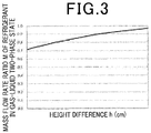
- FIG. 3 is a relational view between the height difference and the mass flow rate ratio of the refrigerant in a gas-liquid two-phase state.
- FIG. 3 is a graph illustrating the relationship between the height difference h and the mass flow rate ratio m of the refrigerant in a gas-liquid two-phase state based on the expression (1).
- the flow rate of the gas-liquid two-phase refrigerant flowing from the joining portion 123 to the injection compressor 111 largely depends on the volumetric flow rate depending on the structure of the injection mechanism portion, and thus the height difference h is calculated, assuming that the volumetric flow rate is constant.
- the height difference h may be calculated by the following expression (2). ⁇ ′ gh ⁇ 0.5 ⁇ ⁇ ′ v ′ ⁇ 2 ⁇ 0.5 ⁇ ⁇ " v " ⁇ 2 + ⁇ P
- FIG. 4 is a configuration view of a refrigeration cycle apparatus according to a second embodiment of the present invention.
- a suction bypass pipe 126 is a refrigerant pipe which branches between the first branch portion 120 and an outdoor unit connecting portion 125 and connects to a suction pipe 128.
- a suction bypass flow control device 127 is a device which controls the flow rate of the refrigerant flowing in the suction bypass pipe 126.
- a first supercooling heat exchanger 124 is a heat exchanger which can exchange heat with the refrigerant flowing in the injection pipe 118. The first supercooling heat exchanger 124 is structured to allow each of the refrigerant flowing in the suction bypass pipe 126 and the refrigerant flowing in the injection pipe 118 to circulate through each partitioned flow path.
- a plate heat exchanger or a double tube heat exchanger is commonly used as the first supercooling heat exchanger 124.
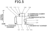
- FIG. 5 is an elevational view, as seen from the horizontal direction, of the injection circuit according to the second embodiment of the present invention.
- a rising pipe portion 129 is a refrigerant pipe disposed between the outdoor unit connecting portion 125 and the first branch portion 120 so that the first branch portion 120 is located on an upper side in a vertical direction than the joining portion 123.
- the first supercooling heat exchanger 124 is provided in the rising pipe portion 129 or between the rising pipe portion 129 and the outdoor unit connecting portion 125.
- the refrigerant enters the injection compressor 111 where the refrigerant is compressed to a high pressure and discharged from the injection compressor 111. Then, the refrigerant passes through the discharge pipe 112 and is discharged from the outdoor air conditioning unit 101 to the indoor air conditioning unit 102. In the indoor air conditioning unit 102, the refrigerant enters the indoor heat exchanger 113 where the refrigerant dissipates heat to the surrounding air and condenses into a high pressure supercooled liquid state. Then, the refrigerant enters the first pressure regulating device 114 where the refrigerant expands to an intermediate pressure and enters a gas-liquid two-phase state, and then is discharged from the indoor air conditioning unit 102.
- the refrigerant discharged from the first supercooling heat exchanger 124 branches at the first branch portion 120, a part of the refrigerant flows into the injection pipe 118, and the remaining refrigerant enters the gas-liquid separator 121.
- the refrigerant in a gas-liquid two-phase state enters the gas-liquid separator 121 where the refrigerant is separated into a gas phase refrigerant and a liquid phase refrigerant.
- the gas phase refrigerant flows into the gas bypass pipe 122, while the liquid phase refrigerant is discharged from the gas-liquid separator 121 and enters the second pressure regulating device 116.
- the second pressure regulating device 116 depressurizes the refrigerant.
- the depressurized refrigerant enters the outdoor heat exchanger 117 where heat is removed from the surrounding air, evaporating to a low pressure superheated gas state, and enters the injection compressor 111.
- the flow control device 119 When the temperature of the refrigerant discharged from the injection compressor 111 is increased or the like, the flow control device 119 is opened thereby to allow the refrigerant in a gas-liquid two-phase state to flow into the injection pipe 118. More specifically, the refrigerant flowing in the injection pipe 118 passes through the flow control device 119 in the open state and then reaches the joining portion 123 where the refrigerant joins the gas phase refrigerant flowing in the gas bypass pipe 122, and then is supplied to the injection compressor 111.
- the present embodiment comprises the rising pipe portion 129 between the first branch portion 120 and the outdoor unit connecting portion 125; and the first supercooling heat exchanger 124 disposed in the rising pipe portion 129 or between the rising pipe portion 129 and the outdoor unit connecting portion 125, exchanging heat with the refrigerant flowing in the suction bypass pipe 126.
- the refrigerant having a dryness degree of 0.2 to 0.4 in a gas-liquid two-phase state returned to the outdoor air conditioning unit 101 enters the first supercooling heat exchanger 124 where the heat is dissipated to the refrigerant flowing in the suction bypass pipe 126 and the dryness degree becomes equal to or less than 0.2.
- the flow mode becomes an annular flow where the gas phase refrigerant may blow through between the liquid phase refrigerant stuck to the inner wall surface of the pipe and thereby the liquid phase refrigerant may not flow smoothly inside the rising pipe portion 129, but in the present embodiment, in the first supercooling heat exchanger 124, heat is dissipated and the dryness degree becomes 0.2 or less, and thus the flow mode becomes a churn flow where gas and liquid are mixed and flow in the rising pipe portion 129. Therefore, the liquid phase refrigerant is stably supplied to the first branch portion 120.
- the liquid phase refrigerant stably flows in the rising pipe portion 129. Therefore, a sufficient amount of liquid phase refrigerant having a high cooling effect is supplied to the compression unit of the injection compressor 111, thus suppressing an excessive increase in the discharge temperature.
- FIG. 6 is a configuration view of a refrigeration cycle apparatus according to a third embodiment of the present invention.
- a second supercooling heat exchanger 130 is a heat exchanger for exchanging heat between the refrigerant branched at the first branch portion 120 and the refrigerant flowing in the suction pipe 128.
- the second supercooling heat exchanger 130 is disposed between the flow control device 119 and the first branch portion 120.
- the refrigerant enters the injection compressor 111 where the refrigerant is compressed to a high pressure and discharged from the injection compressor 111. Then, the refrigerant passes through the discharge pipe 112 and is discharged from the outdoor air conditioning unit 101 to the indoor air conditioning unit 102. In the indoor air conditioning unit 102, the refrigerant enters the indoor heat exchanger 113 where the refrigerant dissipates heat to the surrounding air and condenses into a high pressure supercooled liquid state. Then, the refrigerant enters the first pressure regulating device 114 where the refrigerant expands to an intermediate pressure and enters a gas-liquid two-phase state, and then is discharged from the indoor air conditioning unit 102.
- the refrigerant returned to the outdoor air conditioning unit 101 branches at the first branch portion 120 where a part of the refrigerant flows into the injection pipe 118. Then, the refrigerant enters the second supercooling heat exchanger 130, where heat is dissipated to the refrigerant flowing in the suction pipe 128. Then, the refrigerant passes through the flow control device 119 and reaches the joining portion 123 where the refrigerant joins the refrigerant flowing in the gas bypass pipe 122 and enters the injection compressor 111. Meanwhile, the remaining refrigerant returned to the outdoor air conditioning unit 101 enters the gas-liquid separator 121.
- the refrigerant in a gas-liquid two-phase state enters the gas-liquid separator 121 where the refrigerant is separated into a gas phase refrigerant and a liquid phase refrigerant.
- the gas phase refrigerant flows into the gas bypass pipe 122, while the liquid phase refrigerant is discharged from the gas-liquid separator 121 and enters the second pressure regulating device 116.
- the second pressure regulating device 116 depressurizes the refrigerant.
- the depressurized refrigerant enters the outdoor heat exchanger 117 where the refrigerant dissipates heat to the surrounding air and evaporates into a low pressure superheated gas state, and then enters the injection compressor 111.
- the flow control device 119 When the temperature of the refrigerant discharged from the injection compressor 111 is increased or the like, the flow control device 119 is opened thereby to allow the refrigerant in a gas-liquid two-phase state to flow into the injection pipe 118. More specifically, the refrigerant flowing in the injection pipe 118 passes through the flow control device 119 in the open state and then reaches the joining portion 123 where the refrigerant joins the gas phase refrigerant flowing in the gas bypass pipe 122, and then is supplied to the injection compressor 111.
- the present embodiment comprises the second supercooling heat exchanger 130 between the flow control device 119 and the first branch portion 120.
- the refrigerant in a gas-liquid two-phase state returned to the outdoor air conditioning unit 101 enters the second supercooling heat exchanger 130 where heat is dissipated to the refrigerant flowing in the suction pipe 128 and enters the supercooled liquid state.
- the refrigerant having a dryness degree of 0.1 or less close to a saturated liquid state maintaining a gas-liquid two-phase state flows in the flow control device 119, a state change easily occurs between a saturated liquid state and a gas-liquid two-phase state due to load fluctuation during indoor air conditioning operation.
- a sudden decrease in the refrigerant flow rate flowing in the flow control device 119 occurs due to volume expansion by the state change from liquid single phase to gas-liquid two phase.
- the second supercooling heat exchanger 130 dissipates heat to the refrigerant flowing in the suction pipe 128, the refrigerant enters the supercooled state and then flows in the flow control device 119. Therefore, the flow rate is stable without a sudden decrease in the refrigerant flow rate and the liquid phase refrigerant is stably supplied to the first branch portion 120.
- the liquid phase refrigerant flowing from the first branch portion 120 to the injection pipe 118 has a small dryness degree and a state change occurs between a saturated liquid state and a gas-liquid two-phase state due to air conditioning load fluctuation of the indoor unit, the liquid phase refrigerant can be stably supplied to the joining portion 123. Therefore, a sufficient amount of liquid phase refrigerant having a high cooling effect is supplied to the compression unit of the compressor, thus suppressing an excessive increase in the discharge temperature.
- the refrigeration cycle apparatus can suppress stagnant flow of the liquid phase refrigerant and allows the liquid phase refrigerant to be supplied to the injection compressor 111 when the refrigerant in a gas-liquid two-phase state depressurized to an intermediate pressure by the first pressure regulating device 114 flows from the first branch portion 120 to the injection pipe 118.
- the refrigeration cycle apparatus of the present invention can suppress a reduction in motor efficiency due to an excessive increase in temperature of gas refrigerant discharged from the compressor causing an increase in the motor winding temperature during air conditioning operation of the indoor unit and thus can be suitably used as a device which can operate with high efficiency.
Landscapes
- Engineering & Computer Science (AREA)
- Physics & Mathematics (AREA)
- Mechanical Engineering (AREA)
- Thermal Sciences (AREA)
- General Engineering & Computer Science (AREA)
- Compression-Type Refrigeration Machines With Reversible Cycles (AREA)
Applications Claiming Priority (1)
| Application Number | Priority Date | Filing Date | Title |
|---|---|---|---|
| JP2018009865A JP6811379B2 (ja) | 2018-01-24 | 2018-01-24 | 冷凍サイクル装置 |
Publications (2)
| Publication Number | Publication Date |
|---|---|
| EP3517859A1 true EP3517859A1 (fr) | 2019-07-31 |
| EP3517859B1 EP3517859B1 (fr) | 2021-09-29 |
Family
ID=63294126
Family Applications (1)
| Application Number | Title | Priority Date | Filing Date |
|---|---|---|---|
| EP18189439.5A Active EP3517859B1 (fr) | 2018-01-24 | 2018-08-17 | Appareil de cycle de réfrigération |
Country Status (2)
| Country | Link |
|---|---|
| EP (1) | EP3517859B1 (fr) |
| JP (1) | JP6811379B2 (fr) |
Cited By (2)
| Publication number | Priority date | Publication date | Assignee | Title |
|---|---|---|---|---|
| CN111023605A (zh) * | 2019-12-20 | 2020-04-17 | 北京工业大学 | 一种高压比制冷压缩机分流气液共进补气口协同降温方法 |
| CN115183404A (zh) * | 2022-07-11 | 2022-10-14 | 青岛海尔空调电子有限公司 | 空调系统及其控制方法 |
Citations (4)
| Publication number | Priority date | Publication date | Assignee | Title |
|---|---|---|---|---|
| EP1647783A2 (fr) * | 2004-10-18 | 2006-04-19 | Mitsubishi Denki Kabushiki Kaisha | Équipement de climatisation/réfrigération |
| JP2011052883A (ja) | 2009-09-01 | 2011-03-17 | Mitsubishi Electric Corp | 空気調和機 |
| US20150308701A1 (en) * | 2013-02-19 | 2015-10-29 | Mitsubishi Electric Corporation | Air-conditioning apparatus |
| CN106705508A (zh) * | 2015-08-07 | 2017-05-24 | 丹佛斯(天津)有限公司 | 闪蒸罐和制冷系统 |
Family Cites Families (5)
| Publication number | Priority date | Publication date | Assignee | Title |
|---|---|---|---|---|
| JP2558581Y2 (ja) * | 1990-09-12 | 1997-12-24 | 日本建鐵株式会社 | 冷凍装置 |
| JPH1019392A (ja) * | 1996-07-05 | 1998-01-23 | Sanyo Electric Co Ltd | 冷凍装置 |
| US10088202B2 (en) * | 2009-10-23 | 2018-10-02 | Carrier Corporation | Refrigerant vapor compression system operation |
| JP6134477B2 (ja) * | 2012-01-10 | 2017-05-24 | ジョンソンコントロールズ ヒタチ エア コンディショニング テクノロジー(ホンコン)リミテッド | 冷凍装置及び冷凍機ユニット |
| JP5516712B2 (ja) * | 2012-05-28 | 2014-06-11 | ダイキン工業株式会社 | 冷凍装置 |
-
2018
- 2018-01-24 JP JP2018009865A patent/JP6811379B2/ja active Active
- 2018-08-17 EP EP18189439.5A patent/EP3517859B1/fr active Active
Patent Citations (4)
| Publication number | Priority date | Publication date | Assignee | Title |
|---|---|---|---|---|
| EP1647783A2 (fr) * | 2004-10-18 | 2006-04-19 | Mitsubishi Denki Kabushiki Kaisha | Équipement de climatisation/réfrigération |
| JP2011052883A (ja) | 2009-09-01 | 2011-03-17 | Mitsubishi Electric Corp | 空気調和機 |
| US20150308701A1 (en) * | 2013-02-19 | 2015-10-29 | Mitsubishi Electric Corporation | Air-conditioning apparatus |
| CN106705508A (zh) * | 2015-08-07 | 2017-05-24 | 丹佛斯(天津)有限公司 | 闪蒸罐和制冷系统 |
Cited By (3)
| Publication number | Priority date | Publication date | Assignee | Title |
|---|---|---|---|---|
| CN111023605A (zh) * | 2019-12-20 | 2020-04-17 | 北京工业大学 | 一种高压比制冷压缩机分流气液共进补气口协同降温方法 |
| CN115183404A (zh) * | 2022-07-11 | 2022-10-14 | 青岛海尔空调电子有限公司 | 空调系统及其控制方法 |
| CN115183404B (zh) * | 2022-07-11 | 2024-06-07 | 青岛海尔空调电子有限公司 | 空调系统的控制方法 |
Also Published As
| Publication number | Publication date |
|---|---|
| EP3517859B1 (fr) | 2021-09-29 |
| JP6811379B2 (ja) | 2021-01-13 |
| JP2019128094A (ja) | 2019-08-01 |
Similar Documents
| Publication | Publication Date | Title |
|---|---|---|
| CN105492841B (zh) | 喷射器式制冷循环以及喷射器 | |
| US8783059B2 (en) | Refrigerating air-conditioning apparatus | |
| US5953934A (en) | Refrigerant circulating apparatus and method of assembling a refrigerant circuit | |
| JP2007521456A (ja) | 冷凍システム | |
| EP2942585B1 (fr) | Dispositif de cycle de refroidissement | |
| Bai et al. | Experimental investigation on the dynamic malfunction behavior of the two-phase ejector in a modified auto-cascade freezer refrigeration system | |
| US20200256603A1 (en) | Suction conduit flow control for lubricant management | |
| JP2018004093A (ja) | 冷凍サイクル装置のアキュームレータ | |
| CN206160579U (zh) | 具有液体分离器应用的热回收系统 | |
| JPWO2010137274A1 (ja) | 冷凍サイクル装置 | |
| CN106574807A (zh) | 蒸发器 | |
| EP3517859B1 (fr) | Appareil de cycle de réfrigération | |
| KR20150133565A (ko) | 이코노마이저를 포함하는 응축기 및 이를 포함하는 터보 냉동기 | |
| JP6087610B2 (ja) | 空気調和機 | |
| CN106705508A (zh) | 闪蒸罐和制冷系统 | |
| JP4899641B2 (ja) | 混合流体分離装置 | |
| US20240230167A9 (en) | Refrigeration cycle apparatus | |
| JP4476946B2 (ja) | 冷凍装置 | |
| JP5934931B2 (ja) | 冷凍サイクル装置用タンク及びそれを備えた冷凍サイクル装置 | |
| US20120301268A1 (en) | Supersonic Cooling With Pulsed Inlet and Bypass Loop | |
| JP4082317B2 (ja) | 空気調和装置及び空気調和装置の熱源ユニット | |
| JPWO2015198431A1 (ja) | 冷凍サイクル装置、空気調和装置、及び、冷凍サイクル装置の制御方法 | |
| KR20140069976A (ko) | 증발기 및 이를 포함하는 터보 냉동기 | |
| KR100873141B1 (ko) | 냉난방 장치 | |
| WO2020157806A1 (fr) | Réfrigérateur |
Legal Events
| Date | Code | Title | Description |
|---|---|---|---|
| PUAI | Public reference made under article 153(3) epc to a published international application that has entered the european phase |
Free format text: ORIGINAL CODE: 0009012 |
|
| STAA | Information on the status of an ep patent application or granted ep patent |
Free format text: STATUS: THE APPLICATION HAS BEEN PUBLISHED |
|
| AK | Designated contracting states |
Kind code of ref document: A1 Designated state(s): AL AT BE BG CH CY CZ DE DK EE ES FI FR GB GR HR HU IE IS IT LI LT LU LV MC MK MT NL NO PL PT RO RS SE SI SK SM TR |
|
| AX | Request for extension of the european patent |
Extension state: BA ME |
|
| STAA | Information on the status of an ep patent application or granted ep patent |
Free format text: STATUS: REQUEST FOR EXAMINATION WAS MADE |
|
| 17P | Request for examination filed |
Effective date: 20200131 |
|
| RBV | Designated contracting states (corrected) |
Designated state(s): AL AT BE BG CH CY CZ DE DK EE ES FI FR GB GR HR HU IE IS IT LI LT LU LV MC MK MT NL NO PL PT RO RS SE SI SK SM TR |
|
| REG | Reference to a national code |
Ref country code: DE Ref legal event code: R079 Ref document number: 602018024174 Country of ref document: DE Free format text: PREVIOUS MAIN CLASS: F25B0041040000 Ipc: F25B0041000000 |
|
| RIC1 | Information provided on ipc code assigned before grant |
Ipc: F25B 41/00 20210101AFI20210311BHEP |
|
| GRAP | Despatch of communication of intention to grant a patent |
Free format text: ORIGINAL CODE: EPIDOSNIGR1 |
|
| STAA | Information on the status of an ep patent application or granted ep patent |
Free format text: STATUS: GRANT OF PATENT IS INTENDED |
|
| INTG | Intention to grant announced |
Effective date: 20210428 |
|
| RIN1 | Information on inventor provided before grant (corrected) |
Inventor name: IITAKA, SEISHI |
|
| GRAS | Grant fee paid |
Free format text: ORIGINAL CODE: EPIDOSNIGR3 |
|
| GRAA | (expected) grant |
Free format text: ORIGINAL CODE: 0009210 |
|
| STAA | Information on the status of an ep patent application or granted ep patent |
Free format text: STATUS: THE PATENT HAS BEEN GRANTED |
|
| AK | Designated contracting states |
Kind code of ref document: B1 Designated state(s): AL AT BE BG CH CY CZ DE DK EE ES FI FR GB GR HR HU IE IS IT LI LT LU LV MC MK MT NL NO PL PT RO RS SE SI SK SM TR |
|
| REG | Reference to a national code |
Ref country code: GB Ref legal event code: FG4D |
|
| REG | Reference to a national code |
Ref country code: DE Ref legal event code: R096 Ref document number: 602018024174 Country of ref document: DE |
|
| REG | Reference to a national code |
Ref country code: CH Ref legal event code: EP Ref country code: AT Ref legal event code: REF Ref document number: 1434544 Country of ref document: AT Kind code of ref document: T Effective date: 20211015 |
|
| REG | Reference to a national code |
Ref country code: IE Ref legal event code: FG4D |
|
| REG | Reference to a national code |
Ref country code: LT Ref legal event code: MG9D |
|
| PG25 | Lapsed in a contracting state [announced via postgrant information from national office to epo] |
Ref country code: SE Free format text: LAPSE BECAUSE OF FAILURE TO SUBMIT A TRANSLATION OF THE DESCRIPTION OR TO PAY THE FEE WITHIN THE PRESCRIBED TIME-LIMIT Effective date: 20210929 Ref country code: RS Free format text: LAPSE BECAUSE OF FAILURE TO SUBMIT A TRANSLATION OF THE DESCRIPTION OR TO PAY THE FEE WITHIN THE PRESCRIBED TIME-LIMIT Effective date: 20210929 Ref country code: HR Free format text: LAPSE BECAUSE OF FAILURE TO SUBMIT A TRANSLATION OF THE DESCRIPTION OR TO PAY THE FEE WITHIN THE PRESCRIBED TIME-LIMIT Effective date: 20210929 Ref country code: FI Free format text: LAPSE BECAUSE OF FAILURE TO SUBMIT A TRANSLATION OF THE DESCRIPTION OR TO PAY THE FEE WITHIN THE PRESCRIBED TIME-LIMIT Effective date: 20210929 Ref country code: NO Free format text: LAPSE BECAUSE OF FAILURE TO SUBMIT A TRANSLATION OF THE DESCRIPTION OR TO PAY THE FEE WITHIN THE PRESCRIBED TIME-LIMIT Effective date: 20211229 Ref country code: LT Free format text: LAPSE BECAUSE OF FAILURE TO SUBMIT A TRANSLATION OF THE DESCRIPTION OR TO PAY THE FEE WITHIN THE PRESCRIBED TIME-LIMIT Effective date: 20210929 Ref country code: BG Free format text: LAPSE BECAUSE OF FAILURE TO SUBMIT A TRANSLATION OF THE DESCRIPTION OR TO PAY THE FEE WITHIN THE PRESCRIBED TIME-LIMIT Effective date: 20211229 |
|
| REG | Reference to a national code |
Ref country code: NL Ref legal event code: MP Effective date: 20210929 |
|
| REG | Reference to a national code |
Ref country code: AT Ref legal event code: MK05 Ref document number: 1434544 Country of ref document: AT Kind code of ref document: T Effective date: 20210929 |
|
| PG25 | Lapsed in a contracting state [announced via postgrant information from national office to epo] |
Ref country code: LV Free format text: LAPSE BECAUSE OF FAILURE TO SUBMIT A TRANSLATION OF THE DESCRIPTION OR TO PAY THE FEE WITHIN THE PRESCRIBED TIME-LIMIT Effective date: 20210929 Ref country code: GR Free format text: LAPSE BECAUSE OF FAILURE TO SUBMIT A TRANSLATION OF THE DESCRIPTION OR TO PAY THE FEE WITHIN THE PRESCRIBED TIME-LIMIT Effective date: 20211230 |
|
| PG25 | Lapsed in a contracting state [announced via postgrant information from national office to epo] |
Ref country code: AT Free format text: LAPSE BECAUSE OF FAILURE TO SUBMIT A TRANSLATION OF THE DESCRIPTION OR TO PAY THE FEE WITHIN THE PRESCRIBED TIME-LIMIT Effective date: 20210929 |
|
| PG25 | Lapsed in a contracting state [announced via postgrant information from national office to epo] |
Ref country code: IS Free format text: LAPSE BECAUSE OF FAILURE TO SUBMIT A TRANSLATION OF THE DESCRIPTION OR TO PAY THE FEE WITHIN THE PRESCRIBED TIME-LIMIT Effective date: 20220129 Ref country code: SK Free format text: LAPSE BECAUSE OF FAILURE TO SUBMIT A TRANSLATION OF THE DESCRIPTION OR TO PAY THE FEE WITHIN THE PRESCRIBED TIME-LIMIT Effective date: 20210929 Ref country code: RO Free format text: LAPSE BECAUSE OF FAILURE TO SUBMIT A TRANSLATION OF THE DESCRIPTION OR TO PAY THE FEE WITHIN THE PRESCRIBED TIME-LIMIT Effective date: 20210929 Ref country code: PT Free format text: LAPSE BECAUSE OF FAILURE TO SUBMIT A TRANSLATION OF THE DESCRIPTION OR TO PAY THE FEE WITHIN THE PRESCRIBED TIME-LIMIT Effective date: 20220131 Ref country code: PL Free format text: LAPSE BECAUSE OF FAILURE TO SUBMIT A TRANSLATION OF THE DESCRIPTION OR TO PAY THE FEE WITHIN THE PRESCRIBED TIME-LIMIT Effective date: 20210929 Ref country code: NL Free format text: LAPSE BECAUSE OF FAILURE TO SUBMIT A TRANSLATION OF THE DESCRIPTION OR TO PAY THE FEE WITHIN THE PRESCRIBED TIME-LIMIT Effective date: 20210929 Ref country code: ES Free format text: LAPSE BECAUSE OF FAILURE TO SUBMIT A TRANSLATION OF THE DESCRIPTION OR TO PAY THE FEE WITHIN THE PRESCRIBED TIME-LIMIT Effective date: 20210929 Ref country code: EE Free format text: LAPSE BECAUSE OF FAILURE TO SUBMIT A TRANSLATION OF THE DESCRIPTION OR TO PAY THE FEE WITHIN THE PRESCRIBED TIME-LIMIT Effective date: 20210929 Ref country code: CZ Free format text: LAPSE BECAUSE OF FAILURE TO SUBMIT A TRANSLATION OF THE DESCRIPTION OR TO PAY THE FEE WITHIN THE PRESCRIBED TIME-LIMIT Effective date: 20210929 Ref country code: AL Free format text: LAPSE BECAUSE OF FAILURE TO SUBMIT A TRANSLATION OF THE DESCRIPTION OR TO PAY THE FEE WITHIN THE PRESCRIBED TIME-LIMIT Effective date: 20210929 |
|
| REG | Reference to a national code |
Ref country code: DE Ref legal event code: R097 Ref document number: 602018024174 Country of ref document: DE |
|
| PG25 | Lapsed in a contracting state [announced via postgrant information from national office to epo] |
Ref country code: DK Free format text: LAPSE BECAUSE OF FAILURE TO SUBMIT A TRANSLATION OF THE DESCRIPTION OR TO PAY THE FEE WITHIN THE PRESCRIBED TIME-LIMIT Effective date: 20210929 |
|
| PLBE | No opposition filed within time limit |
Free format text: ORIGINAL CODE: 0009261 |
|
| STAA | Information on the status of an ep patent application or granted ep patent |
Free format text: STATUS: NO OPPOSITION FILED WITHIN TIME LIMIT |
|
| 26N | No opposition filed |
Effective date: 20220630 |
|
| PG25 | Lapsed in a contracting state [announced via postgrant information from national office to epo] |
Ref country code: SI Free format text: LAPSE BECAUSE OF FAILURE TO SUBMIT A TRANSLATION OF THE DESCRIPTION OR TO PAY THE FEE WITHIN THE PRESCRIBED TIME-LIMIT Effective date: 20210929 |
|
| PG25 | Lapsed in a contracting state [announced via postgrant information from national office to epo] |
Ref country code: IT Free format text: LAPSE BECAUSE OF FAILURE TO SUBMIT A TRANSLATION OF THE DESCRIPTION OR TO PAY THE FEE WITHIN THE PRESCRIBED TIME-LIMIT Effective date: 20210929 |
|
| PG25 | Lapsed in a contracting state [announced via postgrant information from national office to epo] |
Ref country code: MC Free format text: LAPSE BECAUSE OF FAILURE TO SUBMIT A TRANSLATION OF THE DESCRIPTION OR TO PAY THE FEE WITHIN THE PRESCRIBED TIME-LIMIT Effective date: 20210929 |
|
| REG | Reference to a national code |
Ref country code: CH Ref legal event code: PL |
|
| GBPC | Gb: european patent ceased through non-payment of renewal fee |
Effective date: 20220817 |
|
| PG25 | Lapsed in a contracting state [announced via postgrant information from national office to epo] |
Ref country code: LU Free format text: LAPSE BECAUSE OF NON-PAYMENT OF DUE FEES Effective date: 20220817 Ref country code: LI Free format text: LAPSE BECAUSE OF NON-PAYMENT OF DUE FEES Effective date: 20220831 Ref country code: CH Free format text: LAPSE BECAUSE OF NON-PAYMENT OF DUE FEES Effective date: 20220831 |
|
| REG | Reference to a national code |
Ref country code: BE Ref legal event code: MM Effective date: 20220831 |
|
| PG25 | Lapsed in a contracting state [announced via postgrant information from national office to epo] |
Ref country code: IE Free format text: LAPSE BECAUSE OF NON-PAYMENT OF DUE FEES Effective date: 20220817 |
|
| PG25 | Lapsed in a contracting state [announced via postgrant information from national office to epo] |
Ref country code: BE Free format text: LAPSE BECAUSE OF NON-PAYMENT OF DUE FEES Effective date: 20220831 |
|
| PG25 | Lapsed in a contracting state [announced via postgrant information from national office to epo] |
Ref country code: GB Free format text: LAPSE BECAUSE OF NON-PAYMENT OF DUE FEES Effective date: 20220817 |
|
| PG25 | Lapsed in a contracting state [announced via postgrant information from national office to epo] |
Ref country code: HU Free format text: LAPSE BECAUSE OF FAILURE TO SUBMIT A TRANSLATION OF THE DESCRIPTION OR TO PAY THE FEE WITHIN THE PRESCRIBED TIME-LIMIT; INVALID AB INITIO Effective date: 20180817 |
|
| PG25 | Lapsed in a contracting state [announced via postgrant information from national office to epo] |
Ref country code: SM Free format text: LAPSE BECAUSE OF FAILURE TO SUBMIT A TRANSLATION OF THE DESCRIPTION OR TO PAY THE FEE WITHIN THE PRESCRIBED TIME-LIMIT Effective date: 20210929 Ref country code: CY Free format text: LAPSE BECAUSE OF FAILURE TO SUBMIT A TRANSLATION OF THE DESCRIPTION OR TO PAY THE FEE WITHIN THE PRESCRIBED TIME-LIMIT Effective date: 20210929 |
|
| PG25 | Lapsed in a contracting state [announced via postgrant information from national office to epo] |
Ref country code: MK Free format text: LAPSE BECAUSE OF FAILURE TO SUBMIT A TRANSLATION OF THE DESCRIPTION OR TO PAY THE FEE WITHIN THE PRESCRIBED TIME-LIMIT Effective date: 20210929 |
|
| PG25 | Lapsed in a contracting state [announced via postgrant information from national office to epo] |
Ref country code: TR Free format text: LAPSE BECAUSE OF FAILURE TO SUBMIT A TRANSLATION OF THE DESCRIPTION OR TO PAY THE FEE WITHIN THE PRESCRIBED TIME-LIMIT Effective date: 20210929 |
|
| PG25 | Lapsed in a contracting state [announced via postgrant information from national office to epo] |
Ref country code: MT Free format text: LAPSE BECAUSE OF FAILURE TO SUBMIT A TRANSLATION OF THE DESCRIPTION OR TO PAY THE FEE WITHIN THE PRESCRIBED TIME-LIMIT Effective date: 20210929 |
|
| PGFP | Annual fee paid to national office [announced via postgrant information from national office to epo] |
Ref country code: DE Payment date: 20240821 Year of fee payment: 7 |
|
| PGFP | Annual fee paid to national office [announced via postgrant information from national office to epo] |
Ref country code: FR Payment date: 20240829 Year of fee payment: 7 |
|
| REG | Reference to a national code |
Ref country code: DE Ref legal event code: R119 Ref document number: 602018024174 Country of ref document: DE |