EP3517867A1 - Armoire mobile de transport polyvalente - Google Patents
Armoire mobile de transport polyvalente Download PDFInfo
- Publication number
- EP3517867A1 EP3517867A1 EP18153770.5A EP18153770A EP3517867A1 EP 3517867 A1 EP3517867 A1 EP 3517867A1 EP 18153770 A EP18153770 A EP 18153770A EP 3517867 A1 EP3517867 A1 EP 3517867A1
- Authority
- EP
- European Patent Office
- Prior art keywords
- fan
- heat exchanger
- heating resistor
- enclosure
- mobile
- Prior art date
- Legal status (The legal status is an assumption and is not a legal conclusion. Google has not performed a legal analysis and makes no representation as to the accuracy of the status listed.)
- Withdrawn
Links
- 238000010438 heat treatment Methods 0.000 claims abstract description 28
- 235000013305 food Nutrition 0.000 claims abstract description 16
- 238000004519 manufacturing process Methods 0.000 claims abstract description 15
- 238000012423 maintenance Methods 0.000 description 3
- 238000010411 cooking Methods 0.000 description 2
- 230000015572 biosynthetic process Effects 0.000 description 1
- 239000003990 capacitor Substances 0.000 description 1
- 235000021270 cold food Nutrition 0.000 description 1
- 230000000295 complement effect Effects 0.000 description 1
- 238000009833 condensation Methods 0.000 description 1
- 230000005494 condensation Effects 0.000 description 1
- 238000001816 cooling Methods 0.000 description 1
- 230000004907 flux Effects 0.000 description 1
- 235000021268 hot food Nutrition 0.000 description 1
- 238000009413 insulation Methods 0.000 description 1
- 238000012986 modification Methods 0.000 description 1
- 230000004048 modification Effects 0.000 description 1
- 238000002360 preparation method Methods 0.000 description 1
- 239000003507 refrigerant Substances 0.000 description 1
- 238000003756 stirring Methods 0.000 description 1
- 238000013024 troubleshooting Methods 0.000 description 1
Images


Classifications
-
- F—MECHANICAL ENGINEERING; LIGHTING; HEATING; WEAPONS; BLASTING
- F25—REFRIGERATION OR COOLING; COMBINED HEATING AND REFRIGERATION SYSTEMS; HEAT PUMP SYSTEMS; MANUFACTURE OR STORAGE OF ICE; LIQUEFACTION SOLIDIFICATION OF GASES
- F25D—REFRIGERATORS; COLD ROOMS; ICE-BOXES; COOLING OR FREEZING APPARATUS NOT OTHERWISE PROVIDED FOR
- F25D17/00—Arrangements for circulating cooling fluids; Arrangements for circulating gas, e.g. air, within refrigerated spaces
- F25D17/04—Arrangements for circulating cooling fluids; Arrangements for circulating gas, e.g. air, within refrigerated spaces for circulating air, e.g. by convection
- F25D17/06—Arrangements for circulating cooling fluids; Arrangements for circulating gas, e.g. air, within refrigerated spaces for circulating air, e.g. by convection by forced circulation
- F25D17/067—Evaporator fan units
-
- F—MECHANICAL ENGINEERING; LIGHTING; HEATING; WEAPONS; BLASTING
- F25—REFRIGERATION OR COOLING; COMBINED HEATING AND REFRIGERATION SYSTEMS; HEAT PUMP SYSTEMS; MANUFACTURE OR STORAGE OF ICE; LIQUEFACTION SOLIDIFICATION OF GASES
- F25D—REFRIGERATORS; COLD ROOMS; ICE-BOXES; COOLING OR FREEZING APPARATUS NOT OTHERWISE PROVIDED FOR
- F25D31/00—Other cooling or freezing apparatus
- F25D31/005—Combined cooling and heating devices
-
- F—MECHANICAL ENGINEERING; LIGHTING; HEATING; WEAPONS; BLASTING
- F25—REFRIGERATION OR COOLING; COMBINED HEATING AND REFRIGERATION SYSTEMS; HEAT PUMP SYSTEMS; MANUFACTURE OR STORAGE OF ICE; LIQUEFACTION SOLIDIFICATION OF GASES
- F25D—REFRIGERATORS; COLD ROOMS; ICE-BOXES; COOLING OR FREEZING APPARATUS NOT OTHERWISE PROVIDED FOR
- F25D2317/00—Details or arrangements for circulating cooling fluids; Details or arrangements for circulating gas, e.g. air, within refrigerated spaces, not provided for in other groups of this subclass
- F25D2317/06—Details or arrangements for circulating cooling fluids; Details or arrangements for circulating gas, e.g. air, within refrigerated spaces, not provided for in other groups of this subclass with forced air circulation
- F25D2317/068—Details or arrangements for circulating cooling fluids; Details or arrangements for circulating gas, e.g. air, within refrigerated spaces, not provided for in other groups of this subclass with forced air circulation characterised by the fans
- F25D2317/0683—Details or arrangements for circulating cooling fluids; Details or arrangements for circulating gas, e.g. air, within refrigerated spaces, not provided for in other groups of this subclass with forced air circulation characterised by the fans the fans not of the axial type
-
- F—MECHANICAL ENGINEERING; LIGHTING; HEATING; WEAPONS; BLASTING
- F25—REFRIGERATION OR COOLING; COMBINED HEATING AND REFRIGERATION SYSTEMS; HEAT PUMP SYSTEMS; MANUFACTURE OR STORAGE OF ICE; LIQUEFACTION SOLIDIFICATION OF GASES
- F25D—REFRIGERATORS; COLD ROOMS; ICE-BOXES; COOLING OR FREEZING APPARATUS NOT OTHERWISE PROVIDED FOR
- F25D2400/00—General features of, or devices for refrigerators, cold rooms, ice-boxes, or for cooling or freezing apparatus not covered by any other subclass
- F25D2400/02—Refrigerators including a heater
-
- F—MECHANICAL ENGINEERING; LIGHTING; HEATING; WEAPONS; BLASTING
- F25—REFRIGERATION OR COOLING; COMBINED HEATING AND REFRIGERATION SYSTEMS; HEAT PUMP SYSTEMS; MANUFACTURE OR STORAGE OF ICE; LIQUEFACTION SOLIDIFICATION OF GASES
- F25D—REFRIGERATORS; COLD ROOMS; ICE-BOXES; COOLING OR FREEZING APPARATUS NOT OTHERWISE PROVIDED FOR
- F25D2400/00—General features of, or devices for refrigerators, cold rooms, ice-boxes, or for cooling or freezing apparatus not covered by any other subclass
- F25D2400/20—Carts specially adapted for transporting objects to be cooled
-
- F—MECHANICAL ENGINEERING; LIGHTING; HEATING; WEAPONS; BLASTING
- F25—REFRIGERATION OR COOLING; COMBINED HEATING AND REFRIGERATION SYSTEMS; HEAT PUMP SYSTEMS; MANUFACTURE OR STORAGE OF ICE; LIQUEFACTION SOLIDIFICATION OF GASES
- F25D—REFRIGERATORS; COLD ROOMS; ICE-BOXES; COOLING OR FREEZING APPARATUS NOT OTHERWISE PROVIDED FOR
- F25D2400/00—General features of, or devices for refrigerators, cold rooms, ice-boxes, or for cooling or freezing apparatus not covered by any other subclass
- F25D2400/38—Refrigerating devices characterised by wheels
Definitions
- the invention relates to a mobile cabinet for transporting food products for the delivery of dishes prepared in a first place and delivered to a second place.
- a mobile hot transport cabinet or a mobile cold transport cabinet is chosen according to the temperature of the food products prepared in advance to be transported.
- the mobile transport cabinet thus chosen is brought to temperature under vacuum and then loaded with food products prepared in advance, already hot or cold corresponding.
- the mobile transport cabinet is then disconnected and moved in isothermal mode to the second place of service to the consumer.
- the mobile transport cabinet remains in isothermal mode until the moment of the service to the consumer itself, or it is postponed in operation to extend the duration of temperature maintenance.
- the mobile transport cabinet is dedicated to a single type, hot or cold, of food products prepared in advance. Therefore, there are a number of these two types of mobile transport cabinets, one for hot food products and the other for cold food products. This has the disadvantage of doubling the equipment.
- An object of the invention is to provide a mobile food transport cabinet that allows greater flexibility.
- a mobile food transport cabinet for conveying dishes prepared in a first place and delivered in a second place, the mobile cabinet comprising an isothermal enclosure, a device for air circulation comprising a fan inside the isothermal enclosure, a first cold production system comprising a heat exchanger in the isothermal enclosure, and a second heat production system comprising a heating resistor in the enclosure isotherm.
- the fan, the heat exchanger and the heating resistor are arranged so that an air flow generated at the output of the fan passes successively through the heating resistor and then the heat exchanger.
- a mobile cabinet 1 transport according to the invention for the delivery of food products, such as dishes, prepared in advance in a first place, to a second place of service to consumers.
- the mobile cabinet 1 of transport according to the invention comprises an isothermal enclosure 10 accessible by a door 15.
- the isothermal enclosure comprises a bottom 11.
- the mobile cabinet 1 of transport according to the invention comprises a cavity 20.
- the mobile cabinet 1 of transport according to the invention comprises a series of rollers 16.
- the mobile cabinet 1 of transport according to the invention comprises a first system of cold production, a second hot production system 32 and an air circulation device 31.
- the assembly comprising the first cold production system 33, the second hot production system 32 and a circulation circulation device 32.
- Air 31 forms a heat treatment device 30 of the air present within the isothermal enclosure 10 of the mobile cabinet 1 of transport according to the invention.
- the air circulation device 31 has the role of generating an air flow F1, F2, F3 within the isothermal enclosure 10.
- the air circulation device 31 comprises a fan 310 mounted solidarity. a 311 axis of training.
- the shaft 311 is movably mounted through an insulating wall forming the bottom 11 of the isothermal enclosure 10.
- the air circulation device 31 further comprises a drive motor 312 mounted outside the enclosure isothermal 10, the drive shaft 311 being coaxially mounted and secured to a rotor of the drive motor 312.
- the fan 31 is, here, a centrifugal fan that draws air into a flow F1 along its axis of rotation and rejects the air thus sucked centrifugally.
- the first cold production system 33 comprises a heat exchanger 330 located within the isothermal enclosure 10.
- the heat exchanger 330 is here an evaporator.
- the first cold production system 33 further comprises an inlet pipe 331 and an outlet pipe 332 fluidly connected to the heat exchanger 330.
- the inlet pipe 331 and the outlet pipe 332 pass through the insulating wall forming the bottom 11. of the isothermal enclosure 10.
- the first cold production system 33 comprises a compressor 333.
- the compressor 333 is fluidly connected to the inlet 331 and outlet 332 pipes.
- the first cooling system 333 production 33 cold comprises, in a manner known per se, an air capacitor and a expansion valve forming an expansion valve, these two elements being fluidly connected to the compressor 333 and the heat exchanger 330 within the inlet pipes 331 and outlet 332, so as to form a refrigerant circuit embedded in the mobile cabinet 1 of transport according to the invention.
- the compressor 333 is positioned in the cavity 20 located under the thermal enclosure 10.
- the second heating system 32 comprises a heating element in the form of a heating resistor 320 positioned in the isothermal enclosure 10.
- the heating resistor 320 is here electrical and comprises two terminals 321 and 322 which pass through the insulating wall forming the bottom 11 of the thermal enclosure 10.
- the heating resistor 320 is shaped spirally and circumferentially surrounds the fan 310 of the air circulation device 31. Thus the generated air flow F3 centrifugally by the fan 310 passes radially through the turns of the heating resistor 320.
- the isothermal enclosure 10 of the mobile cabinet 1 of transport further comprises an air duct or internal duct in which the air flow F3, F2 generated by the fan 310 circulates from channeled way.
- the pipe has a double wall 12 which extends in parallel manner, facing and at a distance from the insulating wall forming the bottom 11 of the thermal enclosure 10. The pipe is thus delimited by the insulating wall forming the bottom 11 and the double wall 12.
- the fan 310, the heating resistor 320 and the heat exchanger 330 Within this pipe, are arranged, the fan 310, the heating resistor 320 and the heat exchanger 330.
- the arrangement of these three elements is such that the air flow F1, F2, F3, generated by the fan 310, passes through, at the output of the fan 310, successively the heating resistor 320 and then the heat exchanger 330.
- the fans 310, heating resistor 320 and heat exchanger 330 are positioned in a lower part of the isothermal enclosure 10.
- the fans 310, heating resistor 320 and heat exchanger 330 are mounted on a portion 110 of the insulating wall forming the bottom 11 of the isothermal enclosure. This portion 110 is fixed attached to the bottom 11 whose insulating wall has a complementary opening for this purpose.
- the potion 110 is removably mounted for ease of maintenance or troubleshooting on the fan 310, heater 320 and heat exchanger 330.
- the heat exchanger 330 is positioned above, in the figures, the fan 310.
- the double wall 12 comprises a or more openings facing the fan 310 so as to allow suction of the air of the isothermal enclosure 10 according to a flow F1 through a thickness of the double wall 12.
- the pipe has a opening ejection of the air flow F2 generated and optionally heat treated by the heating resistor 320 or the heat exchanger 330.
- the mobile cabinet 1 transport according to the invention provides a versatile mobile cabinet that can operate in hot mode or cold mode, thus achieving both functions with a single device. This versatility allows great flexibility in the daily variations in the user's needs of such mobile transport cabinets 1 according to the invention.
Landscapes
- Engineering & Computer Science (AREA)
- Chemical & Material Sciences (AREA)
- Combustion & Propulsion (AREA)
- Physics & Mathematics (AREA)
- Mechanical Engineering (AREA)
- Thermal Sciences (AREA)
- General Engineering & Computer Science (AREA)
- Devices For Warming Or Keeping Food Or Tableware Hot (AREA)
Abstract
Description
- L'invention concerne une armoire mobile de transport de produits alimentaires destinés à l'acheminement de plats préparés en un premier lieu et délivrés en un second lieu.
- Actuellement, les secteurs de la restauration commerciale, de la restauration collective ainsi que celle des traiteurs ont besoins d'acheminer des produits alimentaires préparés, sous forme de plats, à l'avance, sous une température contrôlée, entre un premier lieu, communément appelé cuisine où a lieu la cuisson/préparation, et un second lieu de service au consommateur. Les règles d'hygiène et de sécurité alimentaire, ainsi que la réglementation en la matière, imposent de maintenir la température des produits alimentaires préparés à l'avance dans certaines limites jusqu'au service au consommateur. Les produits alimentaires préparés à l'avance sont soient chauds, avec une température à maintenir au-dessus de 63°C après une phase isotherme de transport, soient froids, avec une température à maintenir en-dessous de 10°C après la phase isotherme de transport. Une fois arrivés sur le second lieu de service au consommateur, les produits alimentaires préparés à l'avance doivent rester dans ces limites de température selon qu'ils sont chauds ou froids. Pour remplir ces rôles, une armoire mobile de transport chaude ou une armoire mobile de transport froide est choisie en fonction de la température des produits alimentaires préparés à l'avance à transporter. De manière usuelle, l'armoire mobile de transport ainsi choisie est mise en température à vide puis chargée en produits alimentaires préparés à l'avance déjà chauds ou froids correspondants. L'armoire mobile de transport est alors débranchée et déplacée en mode isotherme jusqu'au second lieu de service au consommateur. Une fois sur le second lieu de service au consommateur, soit l'armoire mobile de transport reste en mode isotherme jusqu'au moment du service au consommateur en lui-même, soit elle est remise en fonctionnement pour allonger la durée de maintien de la température. Quoi qu'il en soit, l'armoire mobile de transport est dédiée à un seul type, chaud ou froid, de produits alimentaires préparés à l'avance. Il faut donc disposer d'un certain nombre de ces deux types d'armoires mobiles de transport, l'un pour les produits alimentaires chauds et l'autre pour les produits alimentaires froids. Cela a pour inconvénient de doubler les équipements.
- Un but de l'invention est de fournir une armoire mobile de transport de produits alimentaires qui permette une plus grande flexibilité.
- A cette fin, il est prévu, selon l'invention, une armoire mobile de transport de produits alimentaires destinée à acheminer des plats préparés en un premier lieu et délivrés en un second lieu, l'armoire mobile comprenant une enceinte isotherme, un dispositif de circulation d'air comportant un ventilateur à l'intérieur de l'enceinte isotherme, un premier système de production de froid comportant un échangeur thermique dans l'enceinte isotherme, et une deuxième système de production de chaleur comprenant une résistance chauffante dans l'enceinte isotherme. Le ventilateur, l'échangeur thermique et la résistance chauffante sont agencés de sorte qu'un flux d'air généré en sortie du ventilateur traverse successivement la résistance chauffante puis l'échangeur thermique.
- Avantageusement, mais facultativement, l'armoire mobile selon l'invention présente au moins l'une des caractéristiques techniques suivantes:
- le ventilateur, l'échangeur thermique et la résistance chauffante sont positionnés en partie basse de l'enceinte thermique ;
- le ventilateur, l'échangeur thermique et la résistance chauffante sont positionnés sur un fond de l'enceinte thermique ;
- l'enceinte thermique comporte une double paroi formant une canalisation dans laquelle le flux d'air généré circule ;
- la résistance chauffante est spiralée autour du ventilateur ;
- l'échangeur thermique est situé au-dessus du ventilateur ; et,
- le premier système de production de froid comporte en outre un compresseur et un capillaire de détente, tous deux positionnés sous l'enceinte isotherme.
- D'autres caractéristiques et avantages de l'invention ressortiront à la lecture de la description qui suit d'un mode de réalisation de l'invention. Aux dessins annexés :
- la
figure 1 est une vue tridimensionnelle d'une armoire mobile de transport selon l'invention ; - la
figure 2 est une vue de face de l'armoire mobile de transport de lafigure 1 ; - la
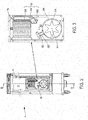
figure 3 est une vue de détail de lafigure 2 ; - la
figure 4 est une vue en coupe selon IV-IV de l'armoire mobile de transport de lafigure 2 ; et - la
figure 5 est une vue de détail de lafigure 4 . - Pour plus de clarté, les éléments identiques ou similaires sont repérés par des signes de référence identiques sur l'ensemble des figures.
- En référence aux
figures 1 à 5 , nous allons décrire une armoire mobile 1 de transport selon l'invention destinée à l'acheminement de produits alimentaires, comme des plats, préparés à l'avance en un premier lieu, vers un second lieu de service à des consommateurs. - L'armoire mobile 1 de transport selon l'invention comporte une enceinte isotherme 10 accessible par une porte 15. L'enceinte isotherme comporte un fond 11. Sous l'enceinte isotherme 10, l'armoire mobile 1 de transport selon l'invention comporte une cavité 20. Afin de permettre son déplacement, l'armoire mobile 1 de transport selon l'invention comprend une série de roulettes 16. D'autre part, l'armoire mobile 1 de transport selon l'invention comporte un premier système de production 33 de froid, un deuxième système de production 32 de chaud et un dispositif de circulation d'air 31. L'ensemble comprenant le premier système de production 33 de froid, le deuxième système de production 32 de chaud et un dispositif de circulation d'air 31 forme un dispositif de traitement thermique 30 de l'air présent au sein de l'enceinte isotherme 10 de l'armoire mobile 1 de transport selon l'invention.
- Le dispositif de circulation d'air 31 a pour rôle de générer un flux d'air F1, F2, F3 au sein de l'enceinte isotherme 10. A cette fin, le dispositif de circulation d'air 31 comporte un ventilateur 310 monté solidaire d'un axe 311 d'entrainement. L'axe 311 est monté mobile à travers une paroi isolante formant le fond 11 de l'enceinte isotherme 10. Le dispositif de circulation d'air 31 comprend en outre un moteur d'entrainement 312, monté à l'extérieur de l'enceinte isotherme 10, l'axe 311 d'entrainement étant monté coaxial et solidaire d'un rotor du moteur d'entrainement 312. Cette disposition permet d'avoir une isolation thermique entre le ventilateur 310, à l'intérieur, et le moteur d'entrainement 312, à l'extérieur, afin à la fois de réduire la montée en température du moteur d'entrainement 312, lors d'un fonctionnement de l'armoire mobile 1 de transport selon l'invention en mode chaud, et la formation de condensation due à l'humidité ambiante coté moteur d'entrainement 312 lors d'un fonctionnement de l'armoire mobile 1 de transport selon l'invention en mode froid. Le ventilateur 31 est, ici, un ventilateur centrifuge qui aspire l'air dans un flux F1 selon son axe de rotation et rejette l'air ainsi aspiré de manière centrifuge.
- Le premier système de production 33 de froid comporte un échangeur thermique 330 situé au sein de l'enceinte isotherme 10. L'échangeur thermique 330 est ici un évaporateur. Le premier système de production 33 de froid comporte en outre une tubulure d'entrée 331 et une tubulure de sortie 332 reliées fluidiquement à l'échangeur thermique 330. Les tubulures d'entrée 331 et de sortie 332 traversent la paroi isolante formant le fond 11 de l'enceinte isotherme 10. Le premier système de production 33 de froid comprend un compresseur 333. Le compresseur 333 est relié fluidiquement aux tubulures d'entrée 331 et de sortie 332. De plus, non illustré sur les figures, le premier système de production 33 de froid comporte, de manière connue en soi, un condensateur à air ainsi qu'un capillaire de détente formant détendeur, ces deux éléments étant reliés fluidiquement au compresseur 333 et à l'échangeur thermique 330 au sein des tubulures d'entrée 331 et de sortie 332, de sorte à former un circuit frigorifique embarqué dans l'armoire mobile 1 de transport selon l'invention. Le compresseur 333 est positionné dans la cavité 20 situé sous l'enceinte thermique 10.
- Le deuxième système de production 32 de chaud comporte, quant à lui, un élément chauffant sous la forme d'une résistance chauffante 320 positionnée dans l'enceinte isotherme 10. D'autres types d'élément chauffant peuvent être utilisés. La résistance chauffante 320 est, ici, électrique et comporte deux bornes 321 et 322 qui passent à travers la paroi isolante formant le fond 11 de l'enceinte thermique 10. Dans le mode de réalisation illustré aux figures, la résistance chauffante 320 est de forme spiralée et entoure circonférentiellement le ventilateur 310 du dispositif de circulation d'air 31. Ainsi le flux d'air généré F3 de manière centrifuge par le ventilateur 310 traverse radialement les spires de la résistance chauffante 320.
- D'autre part, l'enceinte isotherme 10 de l'armoire mobile 1 de transport selon l'invention comporte en outre une gaine d'air ou canalisation intérieure dans laquelle le flux d'air F3, F2 généré par le ventilateur 310 circule de manière canalisée. La canalisation comporte une double paroi 12 qui s'étend de manière parallèle, en regard et à distance de la paroi isolante formant le fond 11 de l'enceinte thermique 10. La canalisation est ainsi délimitée par la paroi isolante formant le fond 11 et la double paroi 12. Au sein de cette canalisation, sont disposés, le ventilateur 310, la résistance chauffante 320 et l'échangeur thermique 330. L'agencement de ces trois éléments est tel que le flux d'air F1, F2, F3, généré par le ventilateur 310, traverse, en sortie du ventilateur 310, successivement la résistance chauffante 320 puis l'échangeur thermique 330.
- Au sein de l'enceinte isotherme 10, les ventilateur 310, résistance chauffante 320 et échangeur thermique 330 sont positionnés dans une partie basse de l'enceinte isotherme 10. Dans une variante de réalisation, les ventilateur 310, résistance chauffante 320 et échangeur thermique 330 sont montés sur une portion 110 de la paroi isolante formant le fond 11 de l'enceinte isotherme. Cette portion 110 est fixée rapportée sur le fond 11 dont la paroi isolante présente une ouverture complémentaire à cette fin. En variante, la potion 110 est montée de manière amovible afin de facilité les interventions d'entretien ou de dépannage sur les ventilateur 310, résistance chauffante 320 et échangeur thermique 330.
- Au sein de la canalisation formée par la double paroi 12 et la paroi isolante formant le fond 11, l'échangeur thermique 330 est positionné au-dessus, sur les figures, du ventilateur 310. D'autre part, la double paroi 12 comporte une ou plusieurs ouvertures en regard du ventilateur 310 de sorte à permettre une aspiration de l'air de l'enceinte isotherme 10 selon un flux F1 traversant une épaisseur de la double paroi 12. En partie haute de l'enceinte isolante, la canalisation comporte une ouverture d'éjection du flux d'air F2 généré et traité éventuellement thermiquement par la résistance chauffante 320 ou l'échangeur thermique 330. Ainsi, une telle circulation de l'air au sein de l'enceinte isotherme 10 permet d'assurer un brassage d'air sur les produits alimentaires stockés.
- L'armoire mobile 1 de transport selon l'invention permet d'obtenir une armoire mobile polyvalente pouvant fonctionner en mode chaud ou en mode froid, permettant ainsi de réaliser les deux fonctions avec un seul appareil. Cette polyvalence permet une grande flexibilité face aux variations journalières des besoins de l'utilisateur de telles armoires mobiles 1 de transport selon l'invention.
- Bien entendu, il est possible d'apporter à l'invention de nombreuse modification sans pour autant sortir du cadre de celle-ci.
Claims (7)
- Armoire mobile (1) de transport de produits alimentaires destinée à acheminer des plats préparés en un premier lieu et délivrés en un second lieu, l'armoire mobile comprenant une enceinte isotherme (10), un dispositif de circulation d'air (31) comportant un ventilateur (310) à l'intérieur de l'enceinte isotherme, un premier système de production (33) de froid comportant un échangeur thermique (330) dans l'enceinte isotherme, et une deuxième système de production (32) de chaleur comprenant une résistance chauffante (320) dans l'enceinte isotherme, caractérisée en ce que le ventilateur, l'échangeur thermique et la résistance chauffante sont agencés de sorte qu'un flux d'air (F1,F2,F3) généré en sortie du ventilateur traverse successivement la résistance chauffante puis l'échangeur thermique.
- Armoire mobile selon la revendication 1, caractérisée en ce que le ventilateur, l'échangeur thermique et la résistance chauffante sont positionnés en partie basse de l'enceinte thermique.
- Armoire mobile selon la revendication 1 ou 2, caractérisée en ce que le ventilateur, l'échangeur thermique et la résistance chauffante sont positionnés sur un fond (11) de l'enceinte thermique.
- Armoire mobile selon l'une des revendications 1 à 3, caractérisée en ce que l'enceinte thermique comporte une double paroi (12) formant une canalisation dans laquelle le flux d'air généré circule.
- Armoire mobile selon l'une des revendications 1 à 4, caractérisée en ce que la résistance chauffante est spiralée autour du ventilateur.
- Armoire mobile selon l'une des revendications 1 à 5, caractérisée en ce que l'échangeur thermique est situé au-dessus du ventilateur.
- Armoire mobile selon l'une des revendications 1 à 6, caractérisée en ce que le premier système de production de froid comporte en outre un compresseur (333) et un capillaire de détente, tous deux positionnés sous l'enceinte isotherme.
Priority Applications (1)
| Application Number | Priority Date | Filing Date | Title |
|---|---|---|---|
| EP18153770.5A EP3517867A1 (fr) | 2018-01-26 | 2018-01-26 | Armoire mobile de transport polyvalente |
Applications Claiming Priority (1)
| Application Number | Priority Date | Filing Date | Title |
|---|---|---|---|
| EP18153770.5A EP3517867A1 (fr) | 2018-01-26 | 2018-01-26 | Armoire mobile de transport polyvalente |
Publications (1)
| Publication Number | Publication Date |
|---|---|
| EP3517867A1 true EP3517867A1 (fr) | 2019-07-31 |
Family
ID=61074350
Family Applications (1)
| Application Number | Title | Priority Date | Filing Date |
|---|---|---|---|
| EP18153770.5A Withdrawn EP3517867A1 (fr) | 2018-01-26 | 2018-01-26 | Armoire mobile de transport polyvalente |
Country Status (1)
| Country | Link |
|---|---|
| EP (1) | EP3517867A1 (fr) |
Citations (4)
| Publication number | Priority date | Publication date | Assignee | Title |
|---|---|---|---|---|
| FR2605395A1 (fr) * | 1986-10-17 | 1988-04-22 | Grandi Rene | Dispositif de production thermique et frigorifique a utilisation par alternance |
| FR2757932A1 (fr) * | 1996-12-31 | 1998-07-03 | Weiss Unweltechnik Gmbh | Procede de conditionnement de gaz ainsi qu'armoire d'essai climatique |
| KR20110033072A (ko) * | 2009-09-24 | 2011-03-30 | 가부시키가이샤 아이호 | 수납장치 |
| WO2013110996A2 (fr) * | 2012-01-27 | 2013-08-01 | Moduline S.R.L. | Appareil combiné pour le maintien de froid et la régénération d'aliments dans l'industrie de la restauration |
-
2018
- 2018-01-26 EP EP18153770.5A patent/EP3517867A1/fr not_active Withdrawn
Patent Citations (4)
| Publication number | Priority date | Publication date | Assignee | Title |
|---|---|---|---|---|
| FR2605395A1 (fr) * | 1986-10-17 | 1988-04-22 | Grandi Rene | Dispositif de production thermique et frigorifique a utilisation par alternance |
| FR2757932A1 (fr) * | 1996-12-31 | 1998-07-03 | Weiss Unweltechnik Gmbh | Procede de conditionnement de gaz ainsi qu'armoire d'essai climatique |
| KR20110033072A (ko) * | 2009-09-24 | 2011-03-30 | 가부시키가이샤 아이호 | 수납장치 |
| WO2013110996A2 (fr) * | 2012-01-27 | 2013-08-01 | Moduline S.R.L. | Appareil combiné pour le maintien de froid et la régénération d'aliments dans l'industrie de la restauration |
Similar Documents
| Publication | Publication Date | Title |
|---|---|---|
| US7823626B2 (en) | Refrigerated oven | |
| FR2514110A1 (fr) | Appareil pour faire cuire ou chauffer des aliments | |
| EP1215444B1 (fr) | Dispositif de four et procédé de commande d'un four | |
| EP1302143B1 (fr) | Cycle de cuisson pour un four réfrigéré | |
| US20170245686A1 (en) | Air fryer | |
| CN104146623A (zh) | 一种带空气炸功能的电烤箱 | |
| CN211933708U (zh) | 空气炸锅 | |
| FR2949656A3 (fr) | Dispositif pour grillade avec fonction de convection d'air chaud | |
| CN110693345A (zh) | 空气炸锅 | |
| CN103690034B (zh) | 具有预约功能的蒸煮装置 | |
| CN114831521A (zh) | 空气炸锅 | |
| EP3517867A1 (fr) | Armoire mobile de transport polyvalente | |
| EP0143066A1 (fr) | Dispositif de distribution de repas avec effets frigorifiques d'attente et de rechauffements intégrés | |
| EP2123202B1 (fr) | Dispositif de cuisson | |
| CN211212611U (zh) | 烹饪器具 | |
| EP3236171B1 (fr) | Caisson extracteur de fumées | |
| CN211933733U (zh) | 具有高效排水汽风道的翻盖式空气炸锅 | |
| CN212307609U (zh) | 一种加热效率高的食物电烤器具 | |
| CN211933727U (zh) | 一种避免热气水平排出的食物电烤器具 | |
| FR3080440A1 (fr) | Systeme de ventilation et centrale de ventilation equipee d'un tel systeme | |
| FR2500966A1 (fr) | Ventilateur entraine par un moteur electrique | |
| CN2288668Y (zh) | 烤箱 | |
| CN219877290U (zh) | 一种用于烘烤糕点的热风旋转炉 | |
| EP0562103B1 (fr) | Dispositif de refrigeration et de cuisson ou de remise en temperature d'aliments pour la distribution automatique de repas | |
| JP2001050538A5 (fr) |
Legal Events
| Date | Code | Title | Description |
|---|---|---|---|
| PUAI | Public reference made under article 153(3) epc to a published international application that has entered the european phase |
Free format text: ORIGINAL CODE: 0009012 |
|
| STAA | Information on the status of an ep patent application or granted ep patent |
Free format text: STATUS: THE APPLICATION HAS BEEN PUBLISHED |
|
| AK | Designated contracting states |
Kind code of ref document: A1 Designated state(s): AL AT BE BG CH CY CZ DE DK EE ES FI FR GB GR HR HU IE IS IT LI LT LU LV MC MK MT NL NO PL PT RO RS SE SI SK SM TR |
|
| AX | Request for extension of the european patent |
Extension state: BA ME |
|
| STAA | Information on the status of an ep patent application or granted ep patent |
Free format text: STATUS: REQUEST FOR EXAMINATION WAS MADE |
|
| 17P | Request for examination filed |
Effective date: 20200131 |
|
| RBV | Designated contracting states (corrected) |
Designated state(s): AL AT BE BG CH CY CZ DE DK EE ES FI FR GB GR HR HU IE IS IT LI LT LU LV MC MK MT NL NO PL PT RO RS SE SI SK SM TR |
|
| STAA | Information on the status of an ep patent application or granted ep patent |
Free format text: STATUS: EXAMINATION IS IN PROGRESS |
|
| 17Q | First examination report despatched |
Effective date: 20220620 |
|
| STAA | Information on the status of an ep patent application or granted ep patent |
Free format text: STATUS: THE APPLICATION IS DEEMED TO BE WITHDRAWN |
|
| 18D | Application deemed to be withdrawn |
Effective date: 20221101 |