EP3518004A2 - Communication récepteur gnss à antenne - Google Patents
Communication récepteur gnss à antenne Download PDFInfo
- Publication number
- EP3518004A2 EP3518004A2 EP19153493.2A EP19153493A EP3518004A2 EP 3518004 A2 EP3518004 A2 EP 3518004A2 EP 19153493 A EP19153493 A EP 19153493A EP 3518004 A2 EP3518004 A2 EP 3518004A2
- Authority
- EP
- European Patent Office
- Prior art keywords
- antenna
- receiver
- module
- side radio
- wired connection
- Prior art date
- Legal status (The legal status is an assumption and is not a legal conclusion. Google has not performed a legal analysis and makes no representation as to the accuracy of the status listed.)
- Granted
Links
Images



Classifications
-
- G—PHYSICS
- G01—MEASURING; TESTING
- G01S—RADIO DIRECTION-FINDING; RADIO NAVIGATION; DETERMINING DISTANCE OR VELOCITY BY USE OF RADIO WAVES; LOCATING OR PRESENCE-DETECTING BY USE OF THE REFLECTION OR RERADIATION OF RADIO WAVES; ANALOGOUS ARRANGEMENTS USING OTHER WAVES
- G01S19/00—Satellite radio beacon positioning systems; Determining position, velocity or attitude using signals transmitted by such systems
- G01S19/01—Satellite radio beacon positioning systems transmitting time-stamped messages, e.g. GPS [Global Positioning System], GLONASS [Global Orbiting Navigation Satellite System] or GALILEO
- G01S19/13—Receivers
- G01S19/35—Constructional details or hardware or software details of the signal processing chain
- G01S19/36—Constructional details or hardware or software details of the signal processing chain relating to the receiver frond end
-
- G—PHYSICS
- G01—MEASURING; TESTING
- G01S—RADIO DIRECTION-FINDING; RADIO NAVIGATION; DETERMINING DISTANCE OR VELOCITY BY USE OF RADIO WAVES; LOCATING OR PRESENCE-DETECTING BY USE OF THE REFLECTION OR RERADIATION OF RADIO WAVES; ANALOGOUS ARRANGEMENTS USING OTHER WAVES
- G01S19/00—Satellite radio beacon positioning systems; Determining position, velocity or attitude using signals transmitted by such systems
- G01S19/01—Satellite radio beacon positioning systems transmitting time-stamped messages, e.g. GPS [Global Positioning System], GLONASS [Global Orbiting Navigation Satellite System] or GALILEO
- G01S19/13—Receivers
-
- G—PHYSICS
- G01—MEASURING; TESTING
- G01S—RADIO DIRECTION-FINDING; RADIO NAVIGATION; DETERMINING DISTANCE OR VELOCITY BY USE OF RADIO WAVES; LOCATING OR PRESENCE-DETECTING BY USE OF THE REFLECTION OR RERADIATION OF RADIO WAVES; ANALOGOUS ARRANGEMENTS USING OTHER WAVES
- G01S19/00—Satellite radio beacon positioning systems; Determining position, velocity or attitude using signals transmitted by such systems
- G01S19/01—Satellite radio beacon positioning systems transmitting time-stamped messages, e.g. GPS [Global Positioning System], GLONASS [Global Orbiting Navigation Satellite System] or GALILEO
- G01S19/13—Receivers
- G01S19/35—Constructional details or hardware or software details of the signal processing chain
-
- H—ELECTRICITY
- H04—ELECTRIC COMMUNICATION TECHNIQUE
- H04B—TRANSMISSION
- H04B1/00—Details of transmission systems, not covered by a single one of groups H04B3/00 - H04B13/00; Details of transmission systems not characterised by the medium used for transmission
- H04B1/06—Receivers
- H04B1/16—Circuits
- H04B1/18—Input circuits, e.g. for coupling to an antenna or a transmission line
Definitions
- GNSS Global navigation satellite systems
- MEO medium Earth orbit
- GNSS receivers use wireless signals that are transmitted from medium Earth orbit (MEO) satellites to GNSS receivers to determine position and velocity information for the GNSS receivers.
- MEO medium Earth orbit
- GNSS receivers use wireless signals that are transmitted from medium Earth orbit (MEO) satellites to determine position and velocity information for the GNSS receivers.
- MEO medium Earth orbit
- GNSS receivers uses wireless signals that are transmitted from medium Earth orbit (MEO) satellites to GNSS receivers to determine position and velocity information for the GNSS receivers.
- GPS Global Positioning System
- GLONASS Russian Global Navigation Satellite System
- EU European Union's
- GNSS receivers are used in a wide range of applications, including navigation (e.g., for automobiles, planes, boats, persons, animals, freight, military precision-guided munitions, etc.), surveying, mapping, and time referencing. Further applications for GNSS technology will become available as new techniques for improving
- GNSS receivers use an external antenna connected via a coaxial cable to receive satellite signals.
- the external antenna may be periodically replaced or upgraded, often with different antenna models than the originally used antenna.
- knowledge of an antenna's phase center along with the precise location and elevation dependence of the antenna phase center may be necessary. Accordingly, if the phase center of the antenna is unknown to the GNSS receiver, the accuracy of any position estimate may be significantly limited.
- a user may often input a phase center based on visual inspection of the antenna or based on the user's best estimate. This process is error prone and may lead to erroneous position estimates, particularly if the user is mistaken as to the antenna model. Accordingly, there is a need in the art for improved methods and systems related to GNSS technology.
- a global navigation satellite system (GNSS) receiver may include an antenna module.
- the antenna module may include an antenna configured to receive wireless signals transmitted by a GNSS satellite.
- the antenna is coupled to a wired connection.
- the antenna module may also include an antenna-side radio coupled to the wired connection.
- the antenna-side radio is configured to perform actions including sending, via the wired connection, an identifying signal to a receiver-side radio.
- the identifying signal includes identification information corresponding to the antenna.
- the GNSS receiver may also include a receiver module.
- the receiver module may include the receiver-side radio coupled to the wired connection.
- the receiver-side radio is configured to perform operations including receiving, via the wired connection, the identifying signal from the antenna-side radio.
- the receiver module may also include a radio frequency (RF) front end coupled to the wired connection and configured to generate a plurality of samples related to the wireless signals.
- the antenna module is configured to removably attach to the receiver module.
- the identification information includes one or more of: an antenna type, an antenna model number, an antenna serial number, a phase center model of the antenna, and a reference point of the antenna.
- the operations further include determining, based on the identifying signal, the identification information, and in response to receiving the identifying signal, sending, via the wired connection, a confirmation signal indicating receipt of the identifying signal by the receiver-side radio.
- the receiver module further includes a user input device configured to be activated by a user.
- the receiver module is configured to receive, via the user input device, an input signal indicating that the antenna module is removably attached to the receiver module.
- the receiver module is configured to send, via the wired connection, a power signal to the antenna-side radio.
- the power signal provides a direct current (DC) voltage to the antenna-side radio.
- DC direct current
- the actions further include receiving, via the wired connection, the power signal from the receiver module.
- the identifying signal is sent by the antenna-side radio in response to receipt of the power signal.
- the operations further include causing a modification of one or more parameters within the RF front end or a receiver processor based on the identification information.
- the receiver processor generates GNSS position data based on the digital samples.
- the receiver module includes the receiver processor.
- the antenna module further comprises at least one sensor configured to record sensor data including one or more of a temperature of the antenna, a movement of the antenna, and an atmospheric pressure.
- the identification information includes the sensor data.
- an antenna module of a GNSS receiver is provided.
- the antenna module may be similar to the antenna module described in reference to the first aspect of the present disclosure.
- a method may include sending, by an antenna-side radio of an antenna module of a global navigation satellite system, an identifying signal to a receiver-side radio of a receiver module of the GNSS system via a wired connection.
- the method may also include receiving, by the receiver-side radio via the wired connection, the identifying signal from the antenna-side radio.
- the method may further include determining, by the receiver-side radio, the identification information based on the identifying signal and, in response to receiving the identifying signal, sending, by the receiver-side radio via the wired connection, a confirmation signal indicating receipt of the identifying signal by the receiver-side radio.
- the method includes receiving, by the receiver module via a user input device, an input signal indicating that the antenna module is removably attached to the receiver module.
- the method may further include steps described in reference to the first aspect of the present disclosure.
- Embodiments of the present disclosure provide systems and methods for global navigation satellite system (GNSS) receiver to antenna communications.
- GNSS global navigation satellite system
- embodiments of the present disclosure include a GNSS receiver having a module-to-module wired communication capability in which an antenna module having a first radio may be attached to a receiver module having a second radio.
- the two radios utilize a wired connection (e.g., a coaxial cable) formed between the two modules by placing one or more communication signals on top of the GNSS signals received by the antenna. This is accomplished by modulating information onto a carrier frequency and multiplexing the modulated information onto a coaxial cable already in use for the GNSS signals.
- the carrier frequency of the communication signals may be higher or lower in frequency than the GNSS signals.
- the coaxial cable may also be employed to send direct current (DC) voltage from the receiver module to the antenna-side radio in the antenna module. Accordingly, the wired connection between the antenna module and the receiver module may allow transmission of information/power at three different frequency regimes to facilitate the module-to-module communication capability.
- DC direct current
- the communication signals between the antenna-side radio and the receiver-side radio may indicate identification information corresponding to the antenna utilized by the GNSS receiver.
- the GNSS receiver may determine a phase center model of the antenna, along with other information that may be used to adjust the processing of the GNSS signals to improve the GNSS receiver's accuracy.
- the two radios have enough memory to store an antenna type, an antenna serial number, a phase center model of the antenna, as well as enough bandwidth to support communications regarding sensor data.
- the sensor data may include antenna temperature (e.g., using a thermometer), antenna movement and inertia (e.g., using an inertial measurement unit (IMU)), atmospheric pressure (e.g., using a barometer), and the like. Sensors may be placed within or near the antenna module and/or the antenna, and may communicate with the antenna-side radio through wired or wireless communication.
- FIG. 1 illustrates a GNSS 150, according to an embodiment of the present disclosure.
- GNSS 150 includes one or more GNSS satellites 102, i.e., space vehicles (SV), in orbit above a GNSS receiver 100.
- GNSS satellites 102 continuously, periodically, or intermittently broadcast wireless signals 104 containing PRN codes modulated onto carrier frequencies (e.g., L1 and/or L2 carrier frequencies).
- Broadcasted wireless signals 104 include both direct wireless signals 106, i.e., signals transmitted and received without reflection off objects, and reflected wireless signals, i.e., signals received by GNSS receiver 100 after reflection off at least one object.
- Direct wireless signals 106 and reflected wireless signals are received by an antenna 112 positioned within, on, or near GNSS receiver 100, which may be a geodetic antenna, a rover antenna, or a handheld receiver antenna, among other possibilities.
- Wireless signals 104 corresponding to different GNSS satellites 102 may include different PRN codes that identify a particular GNSS satellite 102 such that GNSS receiver 100 may associate different distance estimates to different GNSS satellites 102.
- GNSS satellite 102-1 broadcasts wireless signals 104-1 which contain a different PRN code than the PRN code contained in wireless signals 104-2 broadcasted by GNSS satellite 102-2.
- GNSS satellite 102-3 broadcasts wireless signals 104-3 which contain a different PRN code than the PRN codes contained in wireless signals 104-1 and 104-2 broadcasted by GNSS satellites 102-1 and 102-2, respectively.
- GNSS receiver 100 may use the three distance estimates between itself and GNSS satellites 102-1, 102-2, and 102-3 to generate a position estimate through a process called trilateration.
- trilateration involves generating three spheres having center locations corresponding to the locations of the GNSS satellites 102 and radii corresponding to the distance estimates. The three spheres intersect at two locations, one of which is more plausible than the other given the position of the earth. The less plausible location is disregarded and the more plausible location is used as the position estimate for GNSS receiver 100.
- the position estimate may be continuously, periodically, or intermittently updated by generating new distance estimates and performing trilateration using the new distance estimates.
- Subsequent position estimates may benefit from previous position estimates through filtering processes (e.g., Kalman filtering) capable of improving position estimate accuracy. Position estimates may also be determined using other techniques.
- filtering processes e.g., Kalman filtering
- Position estimates may also be determined using other techniques.
- a fourth satellite may be observed to estimate the receiver clock error with respect to the satellite system time.
- FIG. 2 illustrates a block diagram of GNSS receiver 100, according to an embodiment of the present disclosure.
- GNSS receiver 100 includes antenna 112 for receiving wireless signals 104 and sending/routing a signal related to wireless signals 104 to an RF front end 114.
- Antenna 112 may be linearly or circularly polarized, may be mounted or embedded, may be a single antenna or an array antenna, may have a narrow or wide bandwidth, among other possibilities.
- RF front ends are well known in the art, and in some instances include a band-pass filter 116 for initially filtering out undesirable frequency components outside the frequencies of interest, a low-noise amplifier (LNA) 118 for amplifying the received signal, a local oscillator 120 and a mixer 122 for down converting the received signal from RF to intermediate frequencies (IF), a band-pass filter 124 for removing frequency components outside IF, and an analog-to-digital (A/D) converter 126 for sampling the received signal to generate digital samples 128.
- LNA low-noise amplifier
- RF front end 114 includes additional or fewer components than that shown in FIG. 2 .
- RF front end 114 may include a second local oscillator (90 degrees out of phase with respect to local oscillator 120), a second mixer, a second band-pass filter, and a second A/D converter for generating digital samples corresponding to the quadrature component of wireless signals 104.
- Digital samples corresponding to the in-phase component of wireless signals 104 and digital samples corresponding to the quadrature component of wireless signals 104 may both be sent to receiver processor 132.
- digital samples corresponding to both in-phase and quadrature components may be included in digital samples 128.
- receiver processor 132 may include one or more correlators.
- RF front end 114 may include a phase-locked loop (PLL) for synchronizing the phase of local oscillator 120 with the phase of the received signal, and a phase shifter for generating a second mixing signal using local oscillator 120 that is 90 degrees out of phase with local oscillator 120.
- PLL phase-locked loop
- RF front end 114 does not include band-pass filter 116 and LNA 118.
- A/D converter 126 is coupled directly to antenna 112 and samples the RF signal directly without down-conversion to IF.
- RF front end 114 only includes band-pass filter 116 and A/D converter 126. Other possible configurations of RF front end 114 are possible.
- Digital samples 128 generated by RF front end 114 are sent to receiver processor 132.
- receiver processor 132 performs one or more correlations on digital samples 128 using local codes to generate distance estimates between GNSS receiver 100 and GNSS satellites 102.
- one or more components of receiver processor 132 include specific pieces of hardware, such as an application-specific integrated circuit (ASIC) or a field-programmable gate array (FPGA).
- ASIC application-specific integrated circuit
- FPGA field-programmable gate array
- operations performed by receiver processor 132 are performed entirely in software using digital signal processing (DSP) techniques. After generating the distance estimates, receiver processor 132 may perform trilateration to generate a position estimate for GNSS receiver 100.
- DSP digital signal processing
- receiver processor 132 may output GNSS position data 170 comprising a plurality of GNSS points (i.e., position estimates).
- Each of the plurality of GNSS points may be a 3D coordinate represented by three real numbers.
- the three numbers may correspond to latitude, longitude, and elevation.
- the three numbers may correspond to X, Y, and Z positions.
- GNSS position data 170 may be outputted to be displayed to a user, transmitted to a separate device (e.g., computer, smartphone, server, etc.) via a wired or wireless connection, or further processed, among other possibilities.
- FIG. 3 illustrates a block diagram of a GNSS receiver 300, according to an embodiment of the present disclosure.
- One or more components of GNSS receiver 300 may correspond to one or more components of GNSS receiver 100, such as, but not limited to, antenna 112, front end 114, digital samples 128, receiver processor 132, and GNSS position data 170.
- GNSS receiver 300 comprises a multiple module configuration in which an antenna module 352 may be removably attached to a receiver module 354.
- the term "removably attached” may refer to any means of attachment that may allow later separation of the modules and/or any means of attachment that is non-permanent.
- antenna module 352 may be screwed into receiver module 354, fastened to receiver module 354 using screws, bolts, nails, or a snap-fit connection, glued to receiver module 354, secured to receiver module 354 using a cord, suction, or magnets, and the like.
- antenna module 352 may be inserted into a cavity or a receiving portion of receiver module 354, or vice-versa.
- attachment of antenna module 352 to receiver module 354 provides/creates a wired connection 356 between at least one component of antenna module 352 and at least one component of receiver module 354.
- Wired connection 356 may comprise a single conductor or multiple conductors, and may allow bi-directional communication between antenna module 352 and receiver module 354.
- wired connection 356 comprises a coaxial connection (i.e., using a coaxial cable) comprising a copper core, an inner dielectric insulator, a woven copper shield, and an outer plastic sheath.
- the coaxial connection may further include a female-type coaxial connector and a corresponding male-type coaxial connector.
- wired connection 356 is created upon attaching antenna module 352 to receiver module 354 such that wired connection 356 constitutes part of the means of attachment. In some embodiments, wired connection 356 is created after or before attaching antenna module 352 to receiver module 354 such that wired connection 356 is physically separate from the means of attachment. In one particular implementation, antenna module 352 may be secured to a top end of a surveying pole, receiver module 354 may be secured at a distance along the surveying pole, and wired connection 356 may include a coaxial connection between the two running either internally in the surveying pole or along the outside thereof.
- GNSS receiver 300 includes an antenna-side radio 358 within antenna module 352 that communicates with a receiver-side radio 360 within receiver module 354.
- the communication may be one way (e.g., antenna-side radio 358 only transmits and receiver-side radio 360 only receives) or bi-directional, based on a particular implementation.
- antenna-side radio 358 sends identification information corresponding to antenna 112 to receiver-side radio 360 such that receiver-side radio 360 may cause a modification to one or more parameters within front end 114 and/or receiver processor 132 based on the identification information.
- the identification information may include the phase center model of antenna 112 which describes the location of the phase center of antenna 112 relative to a physical point (i.e., reference point) on antenna 112 that can be measured.
- the phase center model may describe the location of the phase center in terms of a vertical offset (from the physical point) and in terms of a horizontal offset (from the physical point).
- the phase center model may further describe how the vertical offset varies as a function of the angle of arrival in elevation of the GNSS signal and how the horizontal offset varies as a function of the angle of arrival in azimuth of the GNSS signal.
- the phase center model may describe how both the vertical offset and the horizontal offset vary as a function of the frequency of the GNSS signal.
- phase center characteristics information may be measured or determined upon manufacture of antenna 112 and may be written onto one or more storage devices within antenna-side radio 358 and later sent from antenna-side radio 358 to receiver-side radio 360 via wired connection 356.
- the identification information may be utilized by one or both of front end 114 and receiver processor 132 such that GNSS position data 170 more accurately reflects the actual position of GNSS receiver 300 (or the physical point being measured) than otherwise would be estimated if the identification information were unknown to GNSS receiver 300.
- communication between antenna module 352 and receiver module 354 is performed by modulating information onto a carrier frequency and multiplexing the modulated information onto wired connection 356 (or a conductor coupled to wired connection 356) such that the modulated information is transmitted via wired connection 356 to the radio that is receiving the information.
- antenna-side radio 358 may modulate identification information (including, e.g., the phase center model of antenna 112) onto a carrier frequency (e.g., a 868 MHz sinusoidal signal) and may send the modulated information to receiver-side radio 360 via wired connection 356.
- each of antenna-side radio 358 and receiver-side radio 360 may include various components necessary for wired and/or wireless communication, such as local oscillators, band-pass filters, LNAs, mixers, A/D converters, and the like.
- antenna module 352 includes an LNA 362 for amplifying the GNSS signal received by antenna 112.
- LNA 362 may improve the performance of GNSS receiver 300 by setting the system noise figure at antenna 112 and preventing degradation of the signal-to-noise ratio (SNR) of the received GNSS signal in the subsequent signal processing.
- SNR signal-to-noise ratio
- the importance of including LNA 362 in GNSS receiver 300 may be significant in implementations in which wired connection 356 is longer than certain distances (e.g., 1 foot).
- amplifying the received GNSS signal may improve communication between antenna-side radio 358 and receiver-side radio 360 by allowing the radios to increase transmitted signal strength without concern for interference with the received GNSS signal.
- receiver module 354 includes a DC power 364.
- DC power 364 may be a DC voltage source or a pathway to an external DC voltage source.
- DC power 364 may be a battery, a conversion mechanism for converting alternating-current (AC) voltage to DC voltage, a photodiode, a conductive pathway to an external DC voltage source, or some other means of providing DC voltage.
- DC power 364 may be coupled to wired connection 356 (or a conductor coupled to wired connection 356) such that DC voltage may be provided to one or more components of antenna module 352.
- receiver module 354 includes a user input device 366 that may be activated by a user.
- user input device 366 may include a button or switch capable of being pressed or flipped by a user to indicate that antenna module 352 has been attached to receiver module 354.
- Other means of physical activation are contemplated.
- user input device 366 may be wirelessly activated by a user by, for example, the user indicating on an external device (e.g., a smart phone) that antenna module 352 has been attached to receiver module 354.
- activation of user input device 366 may cause user input device 366 to generate an input signal that is sent to one or more components of GNSS receiver 300.
- FIG. 4 illustrates a block diagram of GNSS receiver 300, according to an embodiment of the present disclosure.
- wired connection 356 may be represented as having three separate components through which separate signals on separate frequencies may be transmitted, namely, a low-frequency (LF) component 356A, a highfrequency (HF) component 356B, and a DC component 356C.
- antenna-side radio 358 may be configured so as to transmit and receive on LF component 356A and to receive on DC component 356C.
- receiver-side radio 360 may be configured so as to transmit and receive on LF component 356A.
- LNA 362 may be configured so as to receive on DC component 356C.
- DC power 364 may be configured so as to transmit on DC component 356C.
- LF component 356A may include signals having a carrier frequency of 868 MHz and HF component 356B may include lowband GNSS signals having a carrier frequency between 1166 MHz and 1300 MHz and highband GNSS signals having a carrier frequency between 1525 MHz and 1610 MHz.
- FIG. 5 illustrates a method 500 for calibrating GNSS receiver 300, according to an embodiment of the present disclosure.
- Performance of method 500 may include performing additional or fewer steps than that shown in FIG. 5 . Furthermore, the steps shown need not be performed in the order shown. In some embodiments, one or more steps of method 500 may be performed by or initiated by a single processor. In other embodiments, one or more steps of method 500 are performed at least in part by different components of GNSS receiver 300. Steps of method 500 are described below alongside corresponding drawings of FIGS. 6A-6D .
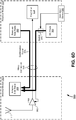
- FIGS. 6A-6D illustrate various steps of method 500 for calibrating GNSS receiver 300, according to an embodiment of the present disclosure.
- an input signal 368 is received at step 502.
- Input signal 368 may indicate that antenna module 352 has been attached to receiver module 354 and/or that a user is ready to operate GNSS receiver 300.
- input signal 368 is received by receiver module 354 via user input device 366.
- user input device 366 may be included in antenna module 352 and input signal 368 may be sent via wired connection 356 to one or more components of receiver module 354.
- input signal 368 may be generated by user input device 366 upon activation of user input device 366 by a user.
- input signal 368 may be generated upon a user pressing a button or flipping a switch or, in some embodiments, user input device 366 may be wirelessly activated by a user using an external device.
- input signal 368 may be received by receiver module 354 via automatic generation of input signal 368 in response to detecting that antenna module 352 has been attached to receiver module 354.
- GNSS receiver 300 may include one or more detectors positioned on one or both of antenna module 352 and receiver module 354 which, upon attachment of antenna module 352 to receiver module 354, generate and send input signal 368 to one or more components of receiver module 354.
- the detectors may include, for example, one or more buttons positioned along the attaching interface between antenna module 352 and receiver module 354.
- the detectors may include one or more touch sensors, proximity sensors, capacitive sensors, and the like.
- input signal 368 is an information-carrying signal. In other embodiments, or in the same embodiments, input signal 368 is a constant DC voltage with a set of possible values indicating whether antenna module 352 is attached to receiver module 354, such as a value of 1.5 V corresponding to attachment and a value of 0 V corresponding to no attachment. In some embodiments, input signal 368 is coupled to a switch 370 such that switch 370 is closed when input signal 368 exceeds a particular threshold and is open when input signal 368 does not exceed the particular threshold. Accordingly, input signal 368 may control the output of one or more components of receiver module 354, such as DC power 364, by opening and closing switch 370.
- a power signal 372 is sent from DC power 364 to antenna-side radio 358 at step 504.
- Power signal 372 may be sent via wired connection 356, or via a separate wired connection between antenna module 352 and receiver module 354.
- Power signal 372 may be sent in response to input signal 368 causing switch 370 to close.
- input signal 368 may cause DC power 364 to turn on or off, thus saving battery when antenna-side radio 358 is not in use.
- power signal 372 is a constant DC voltage, such as 100 mV, 500 mV, 1 V, 5 V, 10 V, or the like.
- power signal 372 may also be sent to LNA 362 and/or receiver-side radio 360.
- an identifying signal 374 is sent from antenna-side radio 358 to receiver-side radio 360 at step 506.
- Identifying signal 374 may be sent via wired connection 356, or via a separate wired connection between antenna module 352 and receiver module 354.
- Identifying signal 374 may be sent by antenna-side radio 360 in response to receipt of power signal 372 by antenna-side radio 358.
- identifying signal 374 may be sent immediately upon receipt of power signal 372 or after a predetermined amount of time from receipt of power signal 372.
- antenna-side radio 358 may send identifying signal 374 immediately upon receipt of wireless signals 104 by antenna 112 or after a predetermined amount of time from receipt of wireless signals 104 by antenna 112.
- antenna-side radio 358 may monitor wired connection 356 and/or antenna 112 for the presence of signals having frequency components consistent with GNSS signals. In response to determining the presence of such signals, antenna-side radio 358 may sent identifying signal 374. In another particular implementation, antenna-side radio 358 may monitor wired connection 356 for the presence of signals within a predetermined frequency range (e.g., between 1166 MHz and 1300 MHz) and in response to determining the presence of such signals, determine a specific frequency of the signals (e.g., 1235 MHz) and modify the phase center model based on the specific frequency prior to sending the phase center model to receiver-side radio 360. By pre-modifying the phase center model based on the specific frequency of the received GNSS signals, identifying signal 374 (which contains the phase center model) may include a smaller amount of information and accordingly may be sent on a smaller bandwidth.
- a predetermined frequency range e.g., between 1166 MHz and 1300 MHz
- a specific frequency of the signals e.g
- identifying signal 374 includes identification information corresponding to antenna 112.
- the identification information may allow receiver module 354 to identify antenna 112 and to modify one or more parameters within front end 114 and/or receiver processor 132 based on antenna 112 (i.e., based on the identification information). For example, different antennas have different phase center models which affect the manner in which GNSS signals received by the antennas are processed.
- a parameter within front end 114 and/or receiver processor 132 e.g., a filtering parameter
- the phase center model of antenna 112 may need to be known.
- the identification information directly includes the phase center model of antenna 112.
- the phase center model of antenna 112 can be determined based on other information in the identification information.
- the identification information may include an antenna type of antenna 112, a model number of antenna 112, a serial number of antenna 112, and the like.
- the identification information may include a physical point on antenna 112 from which the phase center can be referenced.
- the identification information includes a library reference number that corresponds to a library accessible to receiver-side radio 360 such that, upon receipt of identifying signal 374, receiver-side radio 360 may access an entry within the library corresponding to the library reference number to determine the phase center model of antenna 112, the antenna type of antenna 112, the model number of antenna 112, the serial number of antenna 112, and the like.
- the library may be located within receiver-side radio 360 or elsewhere within receiver module 354.
- a confirmation signal 376 is sent from receiver-side radio 360 to antenna-side radio 358 at step 508.
- Confirmation signal 376 may indicate successful receipt of identifying signal 374, or may indicate both successful receipt and successful processing of identifying signal 374.
- confirmation signal 376 may be sent by receiver-side radio 360 upon determining, based on the identification information, the phase center model of antenna 112, the antenna type of antenna 112, the model number of antenna 112, the serial number of antenna 112, and the like.
- confirmation signal 376 may include the identification information as received by receiver-side radio 360 so that antenna-side radio 358 may verify that the correct information was received by receiver-side radio 360.
- confirmation signal 376 may cause one or more components within GNSS receiver 300 to turn off.
- receiver-side radio 360 may turn off upon sending confirmation signal 376 and/or antenna-side radio 358 may turn off upon receiving confirmation signal 376.
- confirmation signal 376 may be sent to DC power 364 causing DC power 364 to turn off, or confirmation signal 376 may be sent to switch 370 causing switch 370 to open.
- DC power 364 continues to provide DC voltage to LNA 362 and both antenna-side radio 358 and receiver-side radio 360 stop drawing power from DC power 364 upon sending and receiving confirmation signal 376, respectively. Accordingly, GNSS receiver 300 may continue to benefit from a powered LNA 362 after the identification information has been processed by receiver module 354.
- receipt of confirmation signal 376 may cause antenna-side radio 358 to collect data from one or more sensors within antenna module 352 and to send the sensor data to receiver-side radio 360.
- the sensor data may include antenna temperature (e.g., using a thermometer), antenna movement and inertia (e.g., using an IMU), atmospheric pressure (e.g., using a barometer), and the like.
- Receipt of the sensor data by receiver-side radio 360 may cause receiver module 354 to modify one or more parameters within front end 114 and/or receiver processor 132 based on the sensor data. For example, the phase center model of antenna 112 may be adjusted if it is determined, based on sensor data recorded by an IMU, that antenna 112 has partially moved and/or rotated.
- FIG. 7 illustrates a simplified computer system 700, according to an embodiment of the present disclosure.
- a computer system 700 as illustrated in FIG. 7 may be incorporated into devices such as a portable electronic device, mobile phone, or other device as described herein.
- FIG. 7 provides a schematic illustration of one embodiment of a computer system 700 that can perform some or all of the steps of the methods provided by various embodiments. It should be noted that FIG. 7 is meant only to provide a generalized illustration of various components, any or all of which may be utilized as appropriate. FIG. 7 , therefore, broadly illustrates how individual system elements may be implemented in a relatively separated or more integrated manner.
- the computer system 700 is shown comprising hardware elements that can be electrically coupled via a bus 705, or may otherwise be in communication, as appropriate.
- the hardware elements may include one or more processors 710, including without limitation one or more general-purpose processors and/or one or more special-purpose processors such as digital signal processing chips, graphics acceleration processors, and/or the like; one or more input devices 715, which can include, without limitation a mouse, a keyboard, a camera, and/or the like; and one or more output devices 720, which can include, without limitation a display device, a printer, and/or the like.
- the computer system 700 may further include and/or be in communication with one or more non-transitory storage devices 725, which can comprise, without limitation, local and/or network accessible storage, and/or can include, without limitation, a disk drive, a drive array, an optical storage device, a solid-state storage device, such as a random access memory (“RAM”), and/or a read-only memory (“ROM”), which can be programmable, flash-updateable, and/or the like.
- RAM random access memory
- ROM read-only memory
- Such storage devices may be configured to implement any appropriate data stores, including without limitation, various file systems, database structures, and/or the like.
- the computer system 700 might also include a communications subsystem 730, which can include, without limitation a modem, a network card (wireless or wired), an infrared communication device, a wireless communication device, and/or a chipset such as a BluetoothTM device, an 802.11 device, a WiFi device, a WiMax device, cellular communication facilities, etc., and/or the like.
- the communications subsystem 730 may include one or more input and/or output communication interfaces to permit data to be exchanged with a network such as the network described below to name one example, to other computer systems, and/or any other devices described herein.
- a portable electronic device or similar device may communicate image and/or other information via the communications subsystem 730.
- a portable electronic device e.g. the first electronic device
- the computer system 700 may further comprise a working memory 735, which can include a RAM or ROM device, as described above.
- the computer system 700 also can include software elements, shown as being currently located within the working memory 735, including an operating system 740, device drivers, executable libraries, and/or other code, such as one or more application programs 745, which may comprise computer programs provided by various embodiments, and/or may be designed to implement methods, and/or configure systems, provided by other embodiments, as described herein.
- an operating system 740 operating system 740
- device drivers executable libraries
- application programs 745 which may comprise computer programs provided by various embodiments, and/or may be designed to implement methods, and/or configure systems, provided by other embodiments, as described herein.
- one or more procedures described with respect to the methods discussed above can be implemented as code and/or instructions executable by a computer and/or a processor within a computer; in an aspect, then, such code and/or instructions can be used to configure and/or adapt a general purpose computer or other device to perform one or more operations in accordance with the described methods.
- a set of these instructions and/or code may be stored on a non-transitory computer-readable storage medium, such as the storage device(s) 725 described above.
- the storage medium might be incorporated within a computer system, such as computer system 700.
- the storage medium might be separate from a computer system e.g., a removable medium, such as a compact disc, and/or provided in an installation package, such that the storage medium can be used to program, configure, and/or adapt a general purpose computer with the instructions/code stored thereon.
- These instructions might take the form of executable code, which is executable by the computer system 700 and/or might take the form of source and/or installable code, which, upon compilation and/or installation on the computer system 700 e.g., using any of a variety of generally available compilers, installation programs, compression/decompression utilities, etc., then takes the form of executable code.
- some embodiments may employ a computer system such as the computer system 700 to perform methods in accordance with various embodiments of the technology. According to a set of embodiments, some or all of the procedures of such methods are performed by the computer system 700 in response to processor 710 executing one or more sequences of one or more instructions, which might be incorporated into the operating system 740 and/or other code, such as an application program 745, contained in the working memory 735. Such instructions may be read into the working memory 735 from another computer-readable medium, such as one or more of the storage device(s) 725. Merely by way of example, execution of the sequences of instructions contained in the working memory 735 might cause the processor(s) 710 to perform one or more procedures of the methods described herein. Additionally or alternatively, portions of the methods described herein may be executed through specialized hardware.
- machine-readable medium and “computer-readable medium,” as used herein, refer to any medium that participates in providing data that causes a machine to operate in a specific fashion.
- various computer-readable media might be involved in providing instructions/code to processor(s) 710 for execution and/or might be used to store and/or carry such instructions/code.
- a computer-readable medium is a physical and/or tangible storage medium.
- Such a medium may take the form of a non-volatile media or volatile media.
- Non-volatile media include, for example, optical and/or magnetic disks, such as the storage device(s) 725.
- Volatile media include, without limitation, dynamic memory, such as the working memory 735.
- Common forms of physical and/or tangible computer-readable media include, for example, a floppy disk, a flexible disk, hard disk, magnetic tape, or any other magnetic medium, a CD-ROM, any other optical medium, punchcards, papertape, any other physical medium with patterns of holes, a RAM, a PROM, EPROM, a FLASH-EPROM, any other memory chip or cartridge, or any other medium from which a computer can read instructions and/or code.
- Various forms of computer-readable media may be involved in carrying one or more sequences of one or more instructions to the processor(s) 710 for execution.
- the instructions may initially be carried on a magnetic disk and/or optical disc of a remote computer.
- a remote computer might load the instructions into its dynamic memory and send the instructions as signals over a transmission medium to be received and/or executed by the computer system 700.
- the communications subsystem 730 and/or components thereof generally will receive signals, and the bus 705 then might carry the signals and/or the data, instructions, etc. carried by the signals to the working memory 735, from which the processor(s) 710 retrieves and executes the instructions.
- the instructions received by the working memory 735 may optionally be stored on a non-transitory storage device 725 either before or after execution by the processor(s) 710.
- configurations may be described as a process which is depicted as a schematic flowchart or block diagram. Although each may describe the operations as a sequential process, many of the operations can be performed in parallel or concurrently. In addition, the order of the operations may be rearranged. A process may have additional steps not included in the figure.
- examples of the methods may be implemented by hardware, software, firmware, middleware, microcode, hardware description languages, or any combination thereof. When implemented in software, firmware, middleware, or microcode, the program code or code segments to perform the necessary tasks may be stored in a non-transitory computer-readable medium such as a storage medium. Processors may perform the described tasks.
Landscapes
- Engineering & Computer Science (AREA)
- Radar, Positioning & Navigation (AREA)
- Remote Sensing (AREA)
- Signal Processing (AREA)
- Computer Networks & Wireless Communication (AREA)
- Physics & Mathematics (AREA)
- General Physics & Mathematics (AREA)
- Position Fixing By Use Of Radio Waves (AREA)
- Input Circuits Of Receivers And Coupling Of Receivers And Audio Equipment (AREA)
- Circuits Of Receivers In General (AREA)
- Radio Relay Systems (AREA)
Applications Claiming Priority (1)
| Application Number | Priority Date | Filing Date | Title |
|---|---|---|---|
| US15/880,912 US11187811B2 (en) | 2018-01-26 | 2018-01-26 | GNSS receiver to antenna communications |
Publications (3)
| Publication Number | Publication Date |
|---|---|
| EP3518004A2 true EP3518004A2 (fr) | 2019-07-31 |
| EP3518004A3 EP3518004A3 (fr) | 2019-09-18 |
| EP3518004B1 EP3518004B1 (fr) | 2021-08-11 |
Family
ID=65228450
Family Applications (1)
| Application Number | Title | Priority Date | Filing Date |
|---|---|---|---|
| EP19153493.2A Active EP3518004B1 (fr) | 2018-01-26 | 2019-01-24 | Communication récepteur gnss à antenne |
Country Status (2)
| Country | Link |
|---|---|
| US (1) | US11187811B2 (fr) |
| EP (1) | EP3518004B1 (fr) |
Cited By (2)
| Publication number | Priority date | Publication date | Assignee | Title |
|---|---|---|---|---|
| EP3961264A3 (fr) * | 2020-08-12 | 2022-05-18 | Rockwell Collins, Inc. | Module récepteur gps |
| EP4075675A1 (fr) * | 2021-04-16 | 2022-10-19 | u-blox AG | Ensemble antenne, ensemble récepteur, leurs procédés de communication et système |
Families Citing this family (1)
| Publication number | Priority date | Publication date | Assignee | Title |
|---|---|---|---|---|
| CN118554994B (zh) * | 2024-04-07 | 2024-10-29 | 柒星通信科技(北京)有限公司 | 一种智能化卫星天线的校准方法 |
Family Cites Families (24)
| Publication number | Priority date | Publication date | Assignee | Title |
|---|---|---|---|---|
| US5943018A (en) * | 1993-08-19 | 1999-08-24 | Toshiba America Information Systems, Inc. | Portable GPS receiver unit |
| JP2001356159A (ja) * | 2000-06-15 | 2001-12-26 | Seiko Epson Corp | Gps受信システム |
| US20030045326A1 (en) * | 2001-09-04 | 2003-03-06 | Bailey James L. | Computer port powered wireless sound transmission and a method therfor |
| JP3656601B2 (ja) * | 2001-12-27 | 2005-06-08 | 株式会社デンソー | Gps受信システム |
| US6928281B2 (en) * | 2002-12-12 | 2005-08-09 | Visteon Global Technologies, Inc. | Active antenna system with fault detection |
| US20040142676A1 (en) * | 2003-01-21 | 2004-07-22 | Sim Wong Hoo | Portable radio module with host adapter |
| TWM250238U (en) * | 2003-02-18 | 2004-11-11 | Royaltek Company Ltd | Receiving and transmitting device for global positioning system |
| US7268727B2 (en) | 2004-04-30 | 2007-09-11 | Paul Yalden Montgomery | Method and apparatus for improved position, velocity, orientation or angular rate sensor |
| US7650173B2 (en) * | 2005-10-06 | 2010-01-19 | Flextronics Ap, Llc | Combined antenna module with single output |
| US9164176B2 (en) | 2007-06-01 | 2015-10-20 | Novatel, Inc. | GNSS receiver and antenna system including a digital communication subsystem |
| EP2000819A1 (fr) * | 2007-06-04 | 2008-12-10 | Leica Geosystems AG | Combinaison d'antennes pour une station GNSS mobile et station GNSS mobile |
| TWI338971B (en) * | 2007-09-10 | 2011-03-11 | Wistron Corp | Electronic device capable of identifying external antenna and related external antenna module |
| JP2009177633A (ja) * | 2008-01-25 | 2009-08-06 | Funai Electric Co Ltd | テレビジョン受像機 |
| US20100134351A1 (en) * | 2008-12-01 | 2010-06-03 | Yang Tsai-Yi | Gps signal transmission apparatus |
| US20110068974A1 (en) * | 2009-09-24 | 2011-03-24 | At&T Intellectual Property I, L.P. | Inline GPS Receiver Module |
| US8446984B2 (en) | 2010-04-05 | 2013-05-21 | Topcon Positioning Systems, Inc. | Method and system for identification of portable antenna modules |
| US20120169537A1 (en) * | 2010-04-30 | 2012-07-05 | Qualcomm Incorporated | Method and apparatus for detecting positioning system antenna connection change |
| US10224979B1 (en) * | 2014-06-09 | 2019-03-05 | Georgia Tech Research Corporation | Reconfigurable aperture antenna |
| US9900037B2 (en) * | 2015-03-25 | 2018-02-20 | Continental Automotive Systems, Inc. | GPS selector from a diversity/MIMO antenna cable |
| US20170261619A1 (en) * | 2016-03-09 | 2017-09-14 | Aeroantenna Technology, Inc. | Global navigation satellite system antenna |
| WO2017188836A1 (fr) | 2016-04-27 | 2017-11-02 | Limited Liability Company "Topcon Positioning Systems" | Antenne gnss équipée d'un élément d'antenne intégré et de sources d'informations supplémentaires |
| US10236564B2 (en) * | 2016-07-27 | 2019-03-19 | Intel Corporation | Wearable electronic device with detachable antenna support |
| KR102515440B1 (ko) * | 2016-08-30 | 2023-03-30 | 삼성전자주식회사 | 방송수신장치 및 그 제어방법 |
| US10725185B2 (en) * | 2017-05-23 | 2020-07-28 | Accord Ideation Private Limited | Sharing of a global navigation satellite system antenna with multiple global navigation satellite system receivers |
-
2018
- 2018-01-26 US US15/880,912 patent/US11187811B2/en active Active
-
2019
- 2019-01-24 EP EP19153493.2A patent/EP3518004B1/fr active Active
Non-Patent Citations (1)
| Title |
|---|
| None |
Cited By (3)
| Publication number | Priority date | Publication date | Assignee | Title |
|---|---|---|---|---|
| EP3961264A3 (fr) * | 2020-08-12 | 2022-05-18 | Rockwell Collins, Inc. | Module récepteur gps |
| US11635528B2 (en) | 2020-08-12 | 2023-04-25 | Rockwell Collins, Inc. | GPS receiver module |
| EP4075675A1 (fr) * | 2021-04-16 | 2022-10-19 | u-blox AG | Ensemble antenne, ensemble récepteur, leurs procédés de communication et système |
Also Published As
| Publication number | Publication date |
|---|---|
| EP3518004A3 (fr) | 2019-09-18 |
| EP3518004B1 (fr) | 2021-08-11 |
| US11187811B2 (en) | 2021-11-30 |
| US20190235089A1 (en) | 2019-08-01 |
Similar Documents
| Publication | Publication Date | Title |
|---|---|---|
| EP3803461B1 (fr) | Système anti-usurpation pour récepteurs gnss | |
| EP3408686B1 (fr) | Rtk hybride | |
| EP2370829B1 (fr) | Récepteurs reconfigurables de systèmes de localisation par satellite | |
| US8872700B2 (en) | GNSS surveying receiver with multiple RTK engines | |
| CN1875289B (zh) | Gps接收器以及相关的方法和设备 | |
| KR102290732B1 (ko) | 클라우드로 오프로드되는 위치 결정 방법 | |
| US8436769B2 (en) | Apparatus for performing global navigation satellite system control, and associated methods and storage media | |
| US20080316092A1 (en) | Methods for processing external correction messages, correcting position measurements of gnss receiver, and related apparatuses | |
| JP2018520335A (ja) | 自動車用gnssリアルタイムキネマティックデッドレコニング受信機 | |
| EP3518004B1 (fr) | Communication récepteur gnss à antenne | |
| EP3607354B1 (fr) | Atténuation de trajets multiples gnss à l'aide d'un discriminateur de code faisant appel à des pentes | |
| US20120112960A1 (en) | Access point, mobile terminal, global navigation satellite system using the access point, and method of providing position information using the access point | |
| US11438861B2 (en) | Using motion state of mobile device for position estimate | |
| CN113093250B (zh) | 伪距观测数据修复方法、定位信息确定方法及装置 | |
| US9341698B1 (en) | Radio frequency jamming source locator | |
| US11255978B2 (en) | Corrections radio antenna mount on the randome of a GNSS receiver | |
| EP4365635A1 (fr) | Calcul de position de vehicule à l'aide de données sécurisées |
Legal Events
| Date | Code | Title | Description |
|---|---|---|---|
| PUAI | Public reference made under article 153(3) epc to a published international application that has entered the european phase |
Free format text: ORIGINAL CODE: 0009012 |
|
| STAA | Information on the status of an ep patent application or granted ep patent |
Free format text: STATUS: THE APPLICATION HAS BEEN PUBLISHED |
|
| AK | Designated contracting states |
Kind code of ref document: A2 Designated state(s): AL AT BE BG CH CY CZ DE DK EE ES FI FR GB GR HR HU IE IS IT LI LT LU LV MC MK MT NL NO PL PT RO RS SE SI SK SM TR |
|
| AX | Request for extension of the european patent |
Extension state: BA ME |
|
| PUAL | Search report despatched |
Free format text: ORIGINAL CODE: 0009013 |
|
| AK | Designated contracting states |
Kind code of ref document: A3 Designated state(s): AL AT BE BG CH CY CZ DE DK EE ES FI FR GB GR HR HU IE IS IT LI LT LU LV MC MK MT NL NO PL PT RO RS SE SI SK SM TR |
|
| AX | Request for extension of the european patent |
Extension state: BA ME |
|
| RIC1 | Information provided on ipc code assigned before grant |
Ipc: G01S 19/36 20100101AFI20190809BHEP |
|
| STAA | Information on the status of an ep patent application or granted ep patent |
Free format text: STATUS: REQUEST FOR EXAMINATION WAS MADE |
|
| 17P | Request for examination filed |
Effective date: 20200317 |
|
| RBV | Designated contracting states (corrected) |
Designated state(s): AL AT BE BG CH CY CZ DE DK EE ES FI FR GB GR HR HU IE IS IT LI LT LU LV MC MK MT NL NO PL PT RO RS SE SI SK SM TR |
|
| STAA | Information on the status of an ep patent application or granted ep patent |
Free format text: STATUS: EXAMINATION IS IN PROGRESS |
|
| 17Q | First examination report despatched |
Effective date: 20200604 |
|
| GRAP | Despatch of communication of intention to grant a patent |
Free format text: ORIGINAL CODE: EPIDOSNIGR1 |
|
| STAA | Information on the status of an ep patent application or granted ep patent |
Free format text: STATUS: GRANT OF PATENT IS INTENDED |
|
| INTG | Intention to grant announced |
Effective date: 20210428 |
|
| GRAS | Grant fee paid |
Free format text: ORIGINAL CODE: EPIDOSNIGR3 |
|
| GRAA | (expected) grant |
Free format text: ORIGINAL CODE: 0009210 |
|
| STAA | Information on the status of an ep patent application or granted ep patent |
Free format text: STATUS: THE PATENT HAS BEEN GRANTED |
|
| AK | Designated contracting states |
Kind code of ref document: B1 Designated state(s): AL AT BE BG CH CY CZ DE DK EE ES FI FR GB GR HR HU IE IS IT LI LT LU LV MC MK MT NL NO PL PT RO RS SE SI SK SM TR |
|
| REG | Reference to a national code |
Ref country code: CH Ref legal event code: EP |
|
| REG | Reference to a national code |
Ref country code: DE Ref legal event code: R096 Ref document number: 602019006681 Country of ref document: DE |
|
| REG | Reference to a national code |
Ref country code: IE Ref legal event code: FG4D Ref country code: AT Ref legal event code: REF Ref document number: 1419949 Country of ref document: AT Kind code of ref document: T Effective date: 20210915 |
|
| REG | Reference to a national code |
Ref country code: LT Ref legal event code: MG9D |
|
| REG | Reference to a national code |
Ref country code: NL Ref legal event code: MP Effective date: 20210811 |
|
| REG | Reference to a national code |
Ref country code: AT Ref legal event code: MK05 Ref document number: 1419949 Country of ref document: AT Kind code of ref document: T Effective date: 20210811 |
|
| PG25 | Lapsed in a contracting state [announced via postgrant information from national office to epo] |
Ref country code: HR Free format text: LAPSE BECAUSE OF FAILURE TO SUBMIT A TRANSLATION OF THE DESCRIPTION OR TO PAY THE FEE WITHIN THE PRESCRIBED TIME-LIMIT Effective date: 20210811 Ref country code: PT Free format text: LAPSE BECAUSE OF FAILURE TO SUBMIT A TRANSLATION OF THE DESCRIPTION OR TO PAY THE FEE WITHIN THE PRESCRIBED TIME-LIMIT Effective date: 20211213 Ref country code: NO Free format text: LAPSE BECAUSE OF FAILURE TO SUBMIT A TRANSLATION OF THE DESCRIPTION OR TO PAY THE FEE WITHIN THE PRESCRIBED TIME-LIMIT Effective date: 20211111 Ref country code: LT Free format text: LAPSE BECAUSE OF FAILURE TO SUBMIT A TRANSLATION OF THE DESCRIPTION OR TO PAY THE FEE WITHIN THE PRESCRIBED TIME-LIMIT Effective date: 20210811 Ref country code: AT Free format text: LAPSE BECAUSE OF FAILURE TO SUBMIT A TRANSLATION OF THE DESCRIPTION OR TO PAY THE FEE WITHIN THE PRESCRIBED TIME-LIMIT Effective date: 20210811 Ref country code: BG Free format text: LAPSE BECAUSE OF FAILURE TO SUBMIT A TRANSLATION OF THE DESCRIPTION OR TO PAY THE FEE WITHIN THE PRESCRIBED TIME-LIMIT Effective date: 20211111 Ref country code: SE Free format text: LAPSE BECAUSE OF FAILURE TO SUBMIT A TRANSLATION OF THE DESCRIPTION OR TO PAY THE FEE WITHIN THE PRESCRIBED TIME-LIMIT Effective date: 20210811 Ref country code: RS Free format text: LAPSE BECAUSE OF FAILURE TO SUBMIT A TRANSLATION OF THE DESCRIPTION OR TO PAY THE FEE WITHIN THE PRESCRIBED TIME-LIMIT Effective date: 20210811 Ref country code: ES Free format text: LAPSE BECAUSE OF FAILURE TO SUBMIT A TRANSLATION OF THE DESCRIPTION OR TO PAY THE FEE WITHIN THE PRESCRIBED TIME-LIMIT Effective date: 20210811 Ref country code: FI Free format text: LAPSE BECAUSE OF FAILURE TO SUBMIT A TRANSLATION OF THE DESCRIPTION OR TO PAY THE FEE WITHIN THE PRESCRIBED TIME-LIMIT Effective date: 20210811 |
|
| PG25 | Lapsed in a contracting state [announced via postgrant information from national office to epo] |
Ref country code: PL Free format text: LAPSE BECAUSE OF FAILURE TO SUBMIT A TRANSLATION OF THE DESCRIPTION OR TO PAY THE FEE WITHIN THE PRESCRIBED TIME-LIMIT Effective date: 20210811 Ref country code: LV Free format text: LAPSE BECAUSE OF FAILURE TO SUBMIT A TRANSLATION OF THE DESCRIPTION OR TO PAY THE FEE WITHIN THE PRESCRIBED TIME-LIMIT Effective date: 20210811 Ref country code: GR Free format text: LAPSE BECAUSE OF FAILURE TO SUBMIT A TRANSLATION OF THE DESCRIPTION OR TO PAY THE FEE WITHIN THE PRESCRIBED TIME-LIMIT Effective date: 20211112 |
|
| PG25 | Lapsed in a contracting state [announced via postgrant information from national office to epo] |
Ref country code: NL Free format text: LAPSE BECAUSE OF FAILURE TO SUBMIT A TRANSLATION OF THE DESCRIPTION OR TO PAY THE FEE WITHIN THE PRESCRIBED TIME-LIMIT Effective date: 20210811 |
|
| PG25 | Lapsed in a contracting state [announced via postgrant information from national office to epo] |
Ref country code: DK Free format text: LAPSE BECAUSE OF FAILURE TO SUBMIT A TRANSLATION OF THE DESCRIPTION OR TO PAY THE FEE WITHIN THE PRESCRIBED TIME-LIMIT Effective date: 20210811 |
|
| REG | Reference to a national code |
Ref country code: DE Ref legal event code: R097 Ref document number: 602019006681 Country of ref document: DE |
|
| PG25 | Lapsed in a contracting state [announced via postgrant information from national office to epo] |
Ref country code: SM Free format text: LAPSE BECAUSE OF FAILURE TO SUBMIT A TRANSLATION OF THE DESCRIPTION OR TO PAY THE FEE WITHIN THE PRESCRIBED TIME-LIMIT Effective date: 20210811 Ref country code: SK Free format text: LAPSE BECAUSE OF FAILURE TO SUBMIT A TRANSLATION OF THE DESCRIPTION OR TO PAY THE FEE WITHIN THE PRESCRIBED TIME-LIMIT Effective date: 20210811 Ref country code: RO Free format text: LAPSE BECAUSE OF FAILURE TO SUBMIT A TRANSLATION OF THE DESCRIPTION OR TO PAY THE FEE WITHIN THE PRESCRIBED TIME-LIMIT Effective date: 20210811 Ref country code: EE Free format text: LAPSE BECAUSE OF FAILURE TO SUBMIT A TRANSLATION OF THE DESCRIPTION OR TO PAY THE FEE WITHIN THE PRESCRIBED TIME-LIMIT Effective date: 20210811 Ref country code: CZ Free format text: LAPSE BECAUSE OF FAILURE TO SUBMIT A TRANSLATION OF THE DESCRIPTION OR TO PAY THE FEE WITHIN THE PRESCRIBED TIME-LIMIT Effective date: 20210811 Ref country code: AL Free format text: LAPSE BECAUSE OF FAILURE TO SUBMIT A TRANSLATION OF THE DESCRIPTION OR TO PAY THE FEE WITHIN THE PRESCRIBED TIME-LIMIT Effective date: 20210811 |
|
| PLBE | No opposition filed within time limit |
Free format text: ORIGINAL CODE: 0009261 |
|
| STAA | Information on the status of an ep patent application or granted ep patent |
Free format text: STATUS: NO OPPOSITION FILED WITHIN TIME LIMIT |
|
| 26N | No opposition filed |
Effective date: 20220512 |
|
| PG25 | Lapsed in a contracting state [announced via postgrant information from national office to epo] |
Ref country code: IT Free format text: LAPSE BECAUSE OF FAILURE TO SUBMIT A TRANSLATION OF THE DESCRIPTION OR TO PAY THE FEE WITHIN THE PRESCRIBED TIME-LIMIT Effective date: 20210811 |
|
| PG25 | Lapsed in a contracting state [announced via postgrant information from national office to epo] |
Ref country code: SI Free format text: LAPSE BECAUSE OF FAILURE TO SUBMIT A TRANSLATION OF THE DESCRIPTION OR TO PAY THE FEE WITHIN THE PRESCRIBED TIME-LIMIT Effective date: 20210811 Ref country code: MC Free format text: LAPSE BECAUSE OF FAILURE TO SUBMIT A TRANSLATION OF THE DESCRIPTION OR TO PAY THE FEE WITHIN THE PRESCRIBED TIME-LIMIT Effective date: 20210811 |
|
| REG | Reference to a national code |
Ref country code: CH Ref legal event code: PL |
|
| REG | Reference to a national code |
Ref country code: BE Ref legal event code: MM Effective date: 20220131 |
|
| PG25 | Lapsed in a contracting state [announced via postgrant information from national office to epo] |
Ref country code: LU Free format text: LAPSE BECAUSE OF NON-PAYMENT OF DUE FEES Effective date: 20220124 |
|
| PG25 | Lapsed in a contracting state [announced via postgrant information from national office to epo] |
Ref country code: BE Free format text: LAPSE BECAUSE OF NON-PAYMENT OF DUE FEES Effective date: 20220131 |
|
| PG25 | Lapsed in a contracting state [announced via postgrant information from national office to epo] |
Ref country code: LI Free format text: LAPSE BECAUSE OF NON-PAYMENT OF DUE FEES Effective date: 20220131 Ref country code: CH Free format text: LAPSE BECAUSE OF NON-PAYMENT OF DUE FEES Effective date: 20220131 |
|
| PG25 | Lapsed in a contracting state [announced via postgrant information from national office to epo] |
Ref country code: IE Free format text: LAPSE BECAUSE OF NON-PAYMENT OF DUE FEES Effective date: 20220124 |
|
| PG25 | Lapsed in a contracting state [announced via postgrant information from national office to epo] |
Ref country code: MK Free format text: LAPSE BECAUSE OF FAILURE TO SUBMIT A TRANSLATION OF THE DESCRIPTION OR TO PAY THE FEE WITHIN THE PRESCRIBED TIME-LIMIT Effective date: 20210811 Ref country code: CY Free format text: LAPSE BECAUSE OF FAILURE TO SUBMIT A TRANSLATION OF THE DESCRIPTION OR TO PAY THE FEE WITHIN THE PRESCRIBED TIME-LIMIT Effective date: 20210811 |
|
| PG25 | Lapsed in a contracting state [announced via postgrant information from national office to epo] |
Ref country code: HU Free format text: LAPSE BECAUSE OF FAILURE TO SUBMIT A TRANSLATION OF THE DESCRIPTION OR TO PAY THE FEE WITHIN THE PRESCRIBED TIME-LIMIT; INVALID AB INITIO Effective date: 20190124 |
|
| PG25 | Lapsed in a contracting state [announced via postgrant information from national office to epo] |
Ref country code: MT Free format text: LAPSE BECAUSE OF FAILURE TO SUBMIT A TRANSLATION OF THE DESCRIPTION OR TO PAY THE FEE WITHIN THE PRESCRIBED TIME-LIMIT Effective date: 20210811 |
|
| PG25 | Lapsed in a contracting state [announced via postgrant information from national office to epo] |
Ref country code: TR Free format text: LAPSE BECAUSE OF FAILURE TO SUBMIT A TRANSLATION OF THE DESCRIPTION OR TO PAY THE FEE WITHIN THE PRESCRIBED TIME-LIMIT Effective date: 20210811 |
|
| PGFP | Annual fee paid to national office [announced via postgrant information from national office to epo] |
Ref country code: GB Payment date: 20260126 Year of fee payment: 8 |
|
| PGFP | Annual fee paid to national office [announced via postgrant information from national office to epo] |
Ref country code: DE Payment date: 20260127 Year of fee payment: 8 |
|
| PGFP | Annual fee paid to national office [announced via postgrant information from national office to epo] |
Ref country code: FR Payment date: 20260126 Year of fee payment: 8 |