EP3518342A1 - Antenne réseau à cornet comprenant un couvercle diélectrique - Google Patents
Antenne réseau à cornet comprenant un couvercle diélectrique Download PDFInfo
- Publication number
- EP3518342A1 EP3518342A1 EP16918934.7A EP16918934A EP3518342A1 EP 3518342 A1 EP3518342 A1 EP 3518342A1 EP 16918934 A EP16918934 A EP 16918934A EP 3518342 A1 EP3518342 A1 EP 3518342A1
- Authority
- EP
- European Patent Office
- Prior art keywords
- horn array
- embossing
- array antenna
- antenna
- horn
- Prior art date
- Legal status (The legal status is an assumption and is not a legal conclusion. Google has not performed a legal analysis and makes no representation as to the accuracy of the status listed.)
- Withdrawn
Links
- 238000004049 embossing Methods 0.000 claims description 60
- 238000005192 partition Methods 0.000 claims description 5
- 235000012489 doughnuts Nutrition 0.000 claims description 4
- 239000004698 Polyethylene Substances 0.000 claims description 3
- 239000004809 Teflon Substances 0.000 claims description 3
- 229920006362 Teflon® Polymers 0.000 claims description 3
- 150000004996 alkyl benzenes Chemical class 0.000 claims description 3
- 229940077388 benzenesulfonate Drugs 0.000 claims description 3
- 239000000463 material Substances 0.000 claims description 3
- 229920000515 polycarbonate Polymers 0.000 claims description 3
- 239000004417 polycarbonate Substances 0.000 claims description 3
- -1 polyethylene Polymers 0.000 claims description 3
- 229920000573 polyethylene Polymers 0.000 claims description 3
- 230000003014 reinforcing effect Effects 0.000 abstract description 4
- 230000003467 diminishing effect Effects 0.000 abstract 1
- 230000002238 attenuated effect Effects 0.000 description 5
- 230000000694 effects Effects 0.000 description 5
- 238000004519 manufacturing process Methods 0.000 description 4
- 238000000034 method Methods 0.000 description 3
- 230000005855 radiation Effects 0.000 description 3
- 238000002474 experimental method Methods 0.000 description 2
- 239000004020 conductor Substances 0.000 description 1
- 230000003247 decreasing effect Effects 0.000 description 1
- 238000001514 detection method Methods 0.000 description 1
- 238000009826 distribution Methods 0.000 description 1
- 230000002093 peripheral effect Effects 0.000 description 1
- 239000004033 plastic Substances 0.000 description 1
- 229920003023 plastic Polymers 0.000 description 1
- 230000001902 propagating effect Effects 0.000 description 1
Images




Classifications
-
- H—ELECTRICITY
- H01—ELECTRIC ELEMENTS
- H01Q—ANTENNAS, i.e. RADIO AERIALS
- H01Q21/00—Antenna arrays or systems
- H01Q21/06—Arrays of individually energised antenna units similarly polarised and spaced apart
- H01Q21/061—Two dimensional planar arrays
- H01Q21/064—Two dimensional planar arrays using horn or slot aerials
-
- H—ELECTRICITY
- H01—ELECTRIC ELEMENTS
- H01Q—ANTENNAS, i.e. RADIO AERIALS
- H01Q13/00—Waveguide horns or mouths; Slot antennas; Leaky-waveguide antennas; Equivalent structures causing radiation along the transmission path of a guided wave
- H01Q13/02—Waveguide horns
-
- H—ELECTRICITY
- H01—ELECTRIC ELEMENTS
- H01Q—ANTENNAS, i.e. RADIO AERIALS
- H01Q15/00—Devices for reflection, refraction, diffraction or polarisation of waves radiated from an antenna, e.g. quasi-optical devices
- H01Q15/02—Refracting or diffracting devices, e.g. lens, prism
- H01Q15/08—Refracting or diffracting devices, e.g. lens, prism formed of solid dielectric material
-
- H—ELECTRICITY
- H01—ELECTRIC ELEMENTS
- H01Q—ANTENNAS, i.e. RADIO AERIALS
- H01Q19/00—Combinations of primary active antenna elements and units with secondary devices, e.g. with quasi-optical devices, for giving the antenna a desired directional characteristic
- H01Q19/06—Combinations of primary active antenna elements and units with secondary devices, e.g. with quasi-optical devices, for giving the antenna a desired directional characteristic using refracting or diffracting devices, e.g. lens
Definitions
- the present invention relates to a horn array antenna, and more particularly, to a horn array antenna including a dielectric cover for reducing a grating lobe.
- An antenna is a device that transmits or receives wireless radio waves in a free space, and is manufactured in various forms and specifications according to the purpose of use thereof.
- An example of the antenna is a horn array antenna.
- FIG. 1 shows one example of the form of a general horn array antenna.
- a horn antenna is a kind of aperture antenna in which a tip of a waveguide (a tubular conductor with an empty center) is formed in a horn shape so that the radio waves may be radiated into space.
- the horn array antenna refers to an antenna in which a plurality of horn antennas as described above are formed in an array on a plane.
- the horn array antenna includes a horn array in which a plurality of horns formed by a plurality of partitions are arranged on a plane, and a radio wave module that transmits or receives radio waves through the horn array.
- a basic structure of such a horn array antenna is disclosed in Korean Patent Laid-Open Publication No. 2012-0014457 ("Horn Array Antenna and Manufacturing Method thereof", 2012. 02. 17).
- An energy distribution of the radio waves radiated from the antenna is generally divided into several directions and each radiation group is called a lobe.
- a lobe in a direction in which radiation energy is maximized is called a main lobe, and the radiation groups in other directions are called side lobes.
- a grating lobe is a special type of signal in the side lobe that appears periodically, and is particularly a signal that appears in the array antenna.
- the side lobe Since a size of the side lobe is significantly smaller than that of the main lobe, noise may be easily removed, but since the grating lobe appears to be significantly strong, the grating lobe is similar in size to the main lobe. Therefore, the grating lobe causes various problems such as causing interference in other equipment, accepting adjacent signals to increase noise, and causing detection errors. Therefore, the development of an array antenna structure for attenuating the grating lobe while reinforcing the main lobe is urgently required.
- the horn array antenna has a problem in that a space is required inside the antenna to dispose a combine circuit and a resonance structure, and a space required for the horn array antenna is increased when the arrangement spacing or the arrangement structure is changed in order to attenuate the grating lobe. That is, the antenna may become thick and large, or efficiency thereof may deteriorate.
- An object of the present invention is to provide a horn array antenna including a dielectric cover for reducing a grating lobe. More specifically, an object of the present invention is to provide a horn array antenna including a dielectric cover, capable of reinforcing a main lobe and effectively attenuating a grating lobe by only further including a dielectric cover in the antenna while not changing an antenna arrangement spacing or an arrangement structure itself in the horn array antenna.
- a horn array antenna 100 including a dielectric cover includes a horn array 110 formed in a form in which a plurality of horns 112 formed by a plurality of partitions 111 are arranged on a plane; an antenna body part 120 provided behind the horn array 110 to transmit or receive radio waves through the horn array 110; and a dielectric cover 130 provided in front of the horn array 110 to refract the radio waves radiated through the horn array 110 to attenuate grating lobes, and formed in a form in which a plurality of embossing cells 132 that protrude forwardly are arranged on the plate 131.
- the embossing cells 132 may be formed in at least one outer shape selected from a dome shape, a lens shape, a donut shape, and a pyramid shape.
- the embossing cells 132 may be formed so that a cross-sectional thickness of one embossing cell 132 is entirely the same or is different for each region.
- the embossing cells 132 may be disposed so that one horn 112 corresponds to one embossing cell 132, or may be disposed so that a plurality of horns 112 correspond to one embossing cell 132.
- the embossing cells 132 may be formed so that a size of each of the plurality of embossing cells 132 arranged on the plate 131 is entirely the same or is different for each region.
- the embossing cells 132 may be formed so that an outer shape of each of the plurality of embossing cells 132 arranged on the plate 131 is entirely the same or is different for each region.
- the dielectric cover may be formed of at least one material selected from Teflon, polyethylene, polycarbonate, and alkyl benzene sulfonate (ABS).
- the grating lobe may be significantly attenuated by covering the front surface of the horn array antenna with the dielectric cover formed in a forwardly convex shape. More specifically, according to the present invention, the beam intensity of a specific angle in a single cell of the horn array antenna is adjusted by intentionally distorting the radiated radio waves using the property that the radio waves are refracted according to the permittivity. Therefore, ultimately, according to the present invention, when a plurality of such cells are arranged, the beam intensity at a desired angle may be adjusted, and as a result, the side lobe (and the grating lobe, which is a kind of side lobe) may be effectively suppressed.
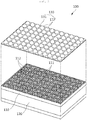
- FIG. 2 shows a horn array antenna 100 including a dielectric cover according to the present invention.
- the horn array antenna 100 according to the present invention basically includes a horn array 110 and an antenna body part 120 similarly to the conventional horn array antenna shown in FIG. 1 , and further includes a dielectric cover 130. A description of each part will be provided below.
- the horn array 110 is formed in the form in which a plurality of horns 112 formed by a plurality of partitions 111 are arranged on a plane as shown.
- a horn antenna is a kind of aperture antenna in which a tip of a waveguide is formed in horn shape so that radio waves may be radiated into space, and the horn array antenna is formed by arranging a plurality of such horn antennas.
- the antenna body part 120 is provided behind the horn array 110 to transmit or receive the radio waves through the horn array 110. That is, the antenna body part 120 includes a module capable of transmitting or receiving the radio waves. Depending on the purpose of use of the horn array antenna 100, the antenna body part 120 may be variously modified such as having only a transmitting module, only a receiving module, or both the transmitting and receiving modules.
- the conventional horn array antenna basically includes only the horn array 110 and the antenna body part 120.
- various attempts have been made to attenuate side lobes, especially, grating lobes, which degrade antenna performance in the conventional horn array antenna.
- the grating lobes are attenuated by changing an antenna arrangement spacing or an arrangement configuration, and in such a case, there is a problem in that a required space is increased and a volume of the antenna is excessively increased.
- the grating lobe is effectively attenuated by providing the dielectric cover 130 in front of the horn array antenna while not changing the antenna arrangement spacing or the arrangement configuration and leaving them unchanged. Accordingly, the antenna performance may be significantly improved by effectively attenuating the grating lobes while basically solving the problem of unnecessarily increasing the volume of the antenna by changing the antenna arrangement.
- the dielectric cover 130 is provided to the front of the horn array 110 as described above to serve to refract the radio waves radiated through the horn array 110 to attenuate the grating lobes.
- a shape of the dielectric cover 130 will be described in more detail, and as shown in FIG. 2 , the dielectric cover 130 is formed in the form in which a plurality of embossing cells 132 that protrude forwardly are arranged on a plate 131.
- the dielectric cover 130 may be formed of a plastic material such as Teflon, polyethylene, polycarbonate, alkyl benzene sulfonate (ABS), or the like.
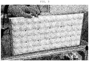
- FIG. 3 shows a photograph of an actual manufacturing example of a dielectric cover according to the present invention.
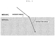
- FIG. 4 illustrates a radio wave refraction principle.
- the radio waves propagating in a space filled with a medium are refracted while a propagation speed thereof changes when permittivity of the medium changes.
- a phenomenon that light refracts in the air as it propagates to the surface, or refracts when passing through a concave lens or a convex lens is also based on such a principle.
- a dielectric lens antenna using a phenomenon in which the radio waves are refracted while passing through a dielectric has been used.
- the dielectric lens antenna is formed in the form in which a dielectric lens is included in a parabolic antenna or a single horn antenna, and FIG. 5 shows an example of a single horn antenna including a dielectric lens.
- Such a conventional dielectric lens antenna has been used for the purpose of increasing a gain as shown in FIG. 5A .
- the beam intensity of a specific angle in a single cell of the horn array antenna is adjusted by intentionally distorting the radiated radio waves unlike the conventional dielectric lens antenna includes the dielectric lens for the purpose of increasing the gain.
- the beam intensity at a desired angle may be ultimately adjusted, and as a result, the side lobe (and the grating lobe, which is a kind of side lobe) may be effectively suppressed. That is, while the conventional dielectric lens has a primary purpose in reinforcing the main lobe, the dielectric cover 130 according to the present invention has a primary purpose in attenuating the side lobe (and the grating lobe).
- the dielectric cover 130 ultimately effectively suppresses the grating lobe by adjusting intensity of the side lobe at the specific angle at the same time of providing no or little loss to the main lobe.
- a performance of the dielectric cover 130 is associated with various factors such as an array type, the number of elements, a frequency of use, permittivity, refraction angle, impedance matching, and reflected waves of peripheral signals.
- a shape of the dielectric cover 130 may also be variously modified according to the various factors.
- examples of various shapes of the dielectric cover 130 will be described in more detail with the drawings.
- FIG. 6 shows various examples of dielectric cover embossing cell form according to the present invention.
- the embossing cell 132 may be formed in a dome shape, a lens shape, a donut shape, a pyramid shape, or the like.
- FIG. 6A shows the dome shape
- FIG. 6B shows the lens shape
- FIG. 6C shows the donut shape
- FIG. 6D shows the pyramid shape, respectively.
- the embossing cell 132 may be formed so that a cross-sectional thickness of one embossing cell 132 is entirely the same or is different for each region.
- the embossing cell 132 may also be formed so that an outer shape of the embossing cell 132 is formed in the dome shape as shown in FIG. 6A and the cross-sectional thickness thereof is entirely the same as shown in the lower left of FIG. 6A , and may also be formed so that the cross-sectional thickness thereof is thick at the central portion and is decreased toward an edge as shown in the lower right of FIG. 6B .
- the embossing cell 132 may also be formed so that the outer shape of the embossing cell 132 is formed in the pyramid shape as shown in FIG. 6D and the cross-sectional thickness thereof is entirely the same as shown in the lower left of FIG. 6D , and may also be formed so that the cross-sectional thickness thereof is thin at the central portion and is increased toward the edge as shown in the lower right of FIG. 6D .
- FIG. 6 various examples of FIG. 6 are to show that although one embossing cell 132 in the present invention has the same shape, the cross-sectional thickness thereof may be variously changed, and the present invention is not limited to such examples.
- the shape of the embossing cell 132 may be variously changed, and the arrangement of the embossing cell 132 may also be variously changed.
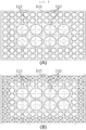
- the embossing cells 132 may also be disposed so that one horn 112 corresponds to one embossing cell 132 as shown in FIG. 7A , or may also be disposed so that a plurality of horns 112 correspond to one embossing cell 132 as shown in FIG. 7B.
- FIG. 7B shows an example in which the embossing cells 132 are disposed so that four horns 112 correspond to one embossing cell 132. Meanwhile, although FIG.
- FIG. 7B shows an example in which the four horns 112 corresponding to one embossing cell 132 are arranged in a 2 x 2 array, the embossing cell 132 may elongate to one side and the four horns 112 corresponding to the embossing cell 132 may also be arranged in a 1 x 4 array or a 4 x 1 array, and that is, a correspondence between the embossing cells and the horns may be variously changed depending on the shape and the size of the embossing cells 132.
- FIG. 8 shows another example of a dielectric cover embossing cell arrangement according to the present invention.
- the size of each of the plurality of embossing cells 132 arranged on the plate 131 is formed to be entirely the same.
- the size of each of the plurality of embossing cells 132 arranged on the plate 131 is formed to be different for each region.
- the example of FIG. 8 shows that the embossing cell 132 disposed at the central portion of the plate 131 is formed to be large and the embossing cell 132 disposed at the edge of the plate 131 is formed to be small.
- the present invention is not limited thereto, and on the contrary to the example of FIG. 8 , the size of the embossing cell may be formed to be reduced toward the central portion, that is, the size of the embossing cell may be variously changed for each plate region.
- the outer shape of each of the plurality of embossing cells 132 arranged on the plate 131 is formed to be entirely the same.
- the outer shape of each of the plurality of embossing cells 132 arranged on the plate 131 is formed to be different for each region.
- FIG. 8B shows an example in which the embossing cells are formed in large and small dome shapes or lens shapes at a central region and the embossing cells 132 are formed in the pyramid shape at an edge region.
- each of the plurality of embossing cells 132 arranged on the plate 131 is formed to be entirely the same or is formed to be different for each region, i.e., may be variously changed.
- FIG. 9 is an experiment result showing a grating lobe attenuation effect according to a comparison between a conventional horn array antenna and the horn array antenna including the dielectric cover according to the present invention.
- Tables below are experiment results of a case (Table 1) in which the dielectric cover 130 is not present and a case (Table 2) in which the dielectric cover 130 is present, and are numerical representations of some of the results of FIG. 9 .
- the horn array antenna including the dielectric cover according to the present invention may significantly attenuate the grating lobes more effectively than the conventional horn array antenna as shown in FIG. 9 , while the main lobe has little or no change in intensity and there is little or no loss in antenna gain, compared to the conventional horn array antenna.
- the present invention is not limited to the abovementioned embodiments, but may be variously applied.
- the present invention may be variously modified by those skilled in the art to which the present invention pertains without departing from the gist of the present invention claimed in the claims.
- the grating lobe may be significantly attenuated by covering the front surface of the horn array antenna with the dielectric cover formed in a forwardly convex shape.
- the grating lobe since there is no need for complicated signal processing or the like, there is also an advantage in that it is not necessary to configure the signal processing unit in a high specification in constituting the apparatus.
Landscapes
- Aerials With Secondary Devices (AREA)
- Waveguide Aerials (AREA)
Applications Claiming Priority (2)
| Application Number | Priority Date | Filing Date | Title |
|---|---|---|---|
| KR20160132281 | 2016-10-12 | ||
| PCT/KR2016/011475 WO2018070566A1 (fr) | 2016-10-12 | 2016-10-13 | Antenne réseau à cornet comprenant un couvercle diélectrique |
Publications (2)
| Publication Number | Publication Date |
|---|---|
| EP3518342A1 true EP3518342A1 (fr) | 2019-07-31 |
| EP3518342A4 EP3518342A4 (fr) | 2020-05-27 |
Family
ID=61905760
Family Applications (1)
| Application Number | Title | Priority Date | Filing Date |
|---|---|---|---|
| EP16918934.7A Withdrawn EP3518342A4 (fr) | 2016-10-12 | 2016-10-13 | Antenne réseau à cornet comprenant un couvercle diélectrique |
Country Status (2)
| Country | Link |
|---|---|
| EP (1) | EP3518342A4 (fr) |
| WO (1) | WO2018070566A1 (fr) |
Cited By (5)
| Publication number | Priority date | Publication date | Assignee | Title |
|---|---|---|---|---|
| KR20210110087A (ko) * | 2020-02-28 | 2021-09-07 | 동우 화인켐 주식회사 | 안테나 소자 및 이를 포함하는 디스플레이 장치 |
| CN113540806A (zh) * | 2021-07-21 | 2021-10-22 | 中国电子科技集团公司第三十八研究所 | 基于3d打印的一体化太赫兹波纹喇叭天线阵列及其制作方法 |
| WO2023276606A1 (fr) * | 2021-07-02 | 2023-01-05 | 株式会社村田製作所 | Antenne réseau à microlentilles, et dispositif radar et véhicule équipé de celle-ci |
| WO2023008268A1 (fr) * | 2021-07-27 | 2023-02-02 | 株式会社村田製作所 | Antenne réseau à microlentilles, et dispositif radar et véhicule équipé de celui-ci |
| EP4172551A4 (fr) * | 2020-06-30 | 2024-04-03 | Paneratech, Inc. | Système de détection de réseau d'antennes |
Families Citing this family (3)
| Publication number | Priority date | Publication date | Assignee | Title |
|---|---|---|---|---|
| US11791565B2 (en) * | 2021-10-11 | 2023-10-17 | Lockheed Martin Corporation | Aperture antenna arrays with aperture mesh |
| KR102734272B1 (ko) * | 2022-11-04 | 2024-11-26 | 엘아이지넥스원 주식회사 | 복사 소자 어레이 구조 및 이를 포함하는 aesa 레이더 시스템 |
| KR102920166B1 (ko) * | 2023-08-04 | 2026-01-30 | 엘아이지넥스원 주식회사 | 복사 소자 조립체 및 이를 포함하는 aesa 레이더 시스템 |
Family Cites Families (8)
| Publication number | Priority date | Publication date | Assignee | Title |
|---|---|---|---|---|
| JPH0739109U (ja) * | 1991-02-14 | 1995-07-14 | 三菱電機株式会社 | ホーンカバー |
| US6359595B1 (en) * | 2000-04-27 | 2002-03-19 | Nortel Networks Limited | Flat plate antenna |
| US6950073B2 (en) * | 2002-08-20 | 2005-09-27 | Aerosat Corporation | Communication system with broadband antenna |
| KR100624049B1 (ko) * | 2004-04-26 | 2006-09-20 | 주식회사 필셋 | 원편파 수신용 정방 격자 혼 배열 안테나 |
| JP2006166399A (ja) * | 2004-11-15 | 2006-06-22 | Maspro Denkoh Corp | Emc試験用アンテナ装置、試験信号発生装置及び送信装置 |
| JP4029217B2 (ja) * | 2005-01-20 | 2008-01-09 | 株式会社村田製作所 | 導波管ホーンアレイアンテナおよびレーダ装置 |
| KR20120014457A (ko) * | 2010-08-09 | 2012-02-17 | 현대모비스 주식회사 | 혼 어레이 안테나 및 그 제조 방법 |
| JP2012175680A (ja) * | 2011-02-24 | 2012-09-10 | Nec Corp | ホーンアレイアンテナ |
-
2016
- 2016-10-13 EP EP16918934.7A patent/EP3518342A4/fr not_active Withdrawn
- 2016-10-13 WO PCT/KR2016/011475 patent/WO2018070566A1/fr not_active Ceased
Cited By (11)
| Publication number | Priority date | Publication date | Assignee | Title |
|---|---|---|---|---|
| KR20210110087A (ko) * | 2020-02-28 | 2021-09-07 | 동우 화인켐 주식회사 | 안테나 소자 및 이를 포함하는 디스플레이 장치 |
| EP4172551A4 (fr) * | 2020-06-30 | 2024-04-03 | Paneratech, Inc. | Système de détection de réseau d'antennes |
| US12276620B2 (en) | 2020-06-30 | 2025-04-15 | Paneratech, Inc. | Antenna-grating coupled sensing system for clutter reduction during evaluation of a status of a material |
| WO2023276606A1 (fr) * | 2021-07-02 | 2023-01-05 | 株式会社村田製作所 | Antenne réseau à microlentilles, et dispositif radar et véhicule équipé de celle-ci |
| JPWO2023276606A1 (fr) * | 2021-07-02 | 2023-01-05 | ||
| JP7768229B2 (ja) | 2021-07-02 | 2025-11-12 | 株式会社村田製作所 | マイクロレンズアレーアンテナ並びにそれを備えたレーダ装置および車両 |
| CN113540806A (zh) * | 2021-07-21 | 2021-10-22 | 中国电子科技集团公司第三十八研究所 | 基于3d打印的一体化太赫兹波纹喇叭天线阵列及其制作方法 |
| CN113540806B (zh) * | 2021-07-21 | 2023-06-06 | 中国电子科技集团公司第三十八研究所 | 基于3d打印的一体化太赫兹波纹喇叭天线阵列及其制作方法 |
| WO2023008268A1 (fr) * | 2021-07-27 | 2023-02-02 | 株式会社村田製作所 | Antenne réseau à microlentilles, et dispositif radar et véhicule équipé de celui-ci |
| JPWO2023008268A1 (fr) * | 2021-07-27 | 2023-02-02 | ||
| JP7582483B2 (ja) | 2021-07-27 | 2024-11-13 | 株式会社村田製作所 | マイクロレンズアレーアンテナ並びにそれを備えたレーダ装置および車両 |
Also Published As
| Publication number | Publication date |
|---|---|
| WO2018070566A1 (fr) | 2018-04-19 |
| EP3518342A4 (fr) | 2020-05-27 |
Similar Documents
| Publication | Publication Date | Title |
|---|---|---|
| EP3518342A1 (fr) | Antenne réseau à cornet comprenant un couvercle diélectrique | |
| KR102110329B1 (ko) | 편광-회전층을 포함하는 안테나 및 레이더 시스템 | |
| US11374311B2 (en) | Millimeter-wave radar cover | |
| CN106532274B (zh) | 基于分裂环超材料单元的双频圆极化平面反射阵天线 | |
| US10050340B2 (en) | Radome | |
| CN110336137B (zh) | 一种阻抗匹配高增益透镜天线及其设计方法 | |
| Pourahmadazar et al. | A millimeter-wave fresnel zone plate lens design using perforated 3D printing material | |
| KR20200018945A (ko) | 평면 렌즈를 포함하는 안테나 장치 | |
| CN110739548B (zh) | 高增益低剖面透射阵列天线 | |
| CN111052507B (zh) | 一种天线及无线设备 | |
| WO2021168846A1 (fr) | Radôme et dispositif de détection | |
| US20240347922A1 (en) | Application of a metasurface lens | |
| KR20100002492A (ko) | 도파관 슬롯 배열 안테나 및 평면형 슬롯 배열 안테나 | |
| JP6314732B2 (ja) | 無線通信モジュール | |
| CN209822868U (zh) | 带平面透镜的天线 | |
| Khang et al. | High-gain Fabry–Perot cavity antenna with an artificial magnetic conductor side wall | |
| RU2435263C1 (ru) | Двухдиапазонная антенна | |
| CN102593606B (zh) | 一种倾斜反射板的超材料天线及卫星电视接收系统 | |
| CN110931983B (zh) | 一种用于平面双极化毫米波宽带频率选择表面 | |
| US11870148B2 (en) | Planar metal Fresnel millimeter-wave lens | |
| GB2182806A (en) | Linearly polarized grid reflector antenna system with improved cross-polarization performance | |
| KR101508074B1 (ko) | 링 패치를 이용한 주파수 선택 표면 | |
| KR102120455B1 (ko) | 광각 특성을 갖는 차량용 레이더 안테나 | |
| CN102683889B (zh) | 一种超材料卫星天线及卫星接收系统 | |
| CN102683811B (zh) | 一种超材料卫星天线及卫星接收系统 |
Legal Events
| Date | Code | Title | Description |
|---|---|---|---|
| PUAI | Public reference made under article 153(3) epc to a published international application that has entered the european phase |
Free format text: ORIGINAL CODE: 0009012 |
|
| STAA | Information on the status of an ep patent application or granted ep patent |
Free format text: STATUS: REQUEST FOR EXAMINATION WAS MADE |
|
| 17P | Request for examination filed |
Effective date: 20190424 |
|
| AK | Designated contracting states |
Kind code of ref document: A1 Designated state(s): AL AT BE BG CH CY CZ DE DK EE ES FI FR GB GR HR HU IE IS IT LI LT LU LV MC MK MT NL NO PL PT RO RS SE SI SK SM TR |
|
| AX | Request for extension of the european patent |
Extension state: BA ME |
|
| RIN1 | Information on inventor provided before grant (corrected) |
Inventor name: PARK, CHANGOO Inventor name: LEE, JUNHEE Inventor name: YANG, SUNGEUN |
|
| DAV | Request for validation of the european patent (deleted) | ||
| DAX | Request for extension of the european patent (deleted) | ||
| A4 | Supplementary search report drawn up and despatched |
Effective date: 20200428 |
|
| RIC1 | Information provided on ipc code assigned before grant |
Ipc: H01Q 13/02 20060101ALI20200421BHEP Ipc: H01Q 21/06 20060101ALI20200421BHEP Ipc: H01Q 15/08 20060101AFI20200421BHEP Ipc: H01Q 19/06 20060101ALI20200421BHEP |
|
| STAA | Information on the status of an ep patent application or granted ep patent |
Free format text: STATUS: THE APPLICATION IS DEEMED TO BE WITHDRAWN |
|
| 18D | Application deemed to be withdrawn |
Effective date: 20201126 |