EP3518558A1 - Mems-mikrofon - Google Patents
Mems-mikrofon Download PDFInfo
- Publication number
- EP3518558A1 EP3518558A1 EP17832031.3A EP17832031A EP3518558A1 EP 3518558 A1 EP3518558 A1 EP 3518558A1 EP 17832031 A EP17832031 A EP 17832031A EP 3518558 A1 EP3518558 A1 EP 3518558A1
- Authority
- EP
- European Patent Office
- Prior art keywords
- vibrating diaphragm
- back electrode
- sealed cavity
- mems microphone
- microphone according
- Prior art date
- Legal status (The legal status is an assumption and is not a legal conclusion. Google has not performed a legal analysis and makes no representation as to the accuracy of the status listed.)
- Granted
Links
Images
Classifications
-
- H—ELECTRICITY
- H04—ELECTRIC COMMUNICATION TECHNIQUE
- H04R—LOUDSPEAKERS, MICROPHONES, GRAMOPHONE PICK-UPS OR LIKE ACOUSTIC ELECTROMECHANICAL TRANSDUCERS; ELECTRIC HEARING AIDS; PUBLIC ADDRESS SYSTEMS
- H04R19/00—Electrostatic transducers
- H04R19/005—Electrostatic transducers using semiconductor materials
-
- H—ELECTRICITY
- H04—ELECTRIC COMMUNICATION TECHNIQUE
- H04R—LOUDSPEAKERS, MICROPHONES, GRAMOPHONE PICK-UPS OR LIKE ACOUSTIC ELECTROMECHANICAL TRANSDUCERS; ELECTRIC HEARING AIDS; PUBLIC ADDRESS SYSTEMS
- H04R7/00—Diaphragms for electromechanical transducers; Cones
- H04R7/02—Diaphragms for electromechanical transducers; Cones characterised by the construction
-
- H—ELECTRICITY
- H04—ELECTRIC COMMUNICATION TECHNIQUE
- H04R—LOUDSPEAKERS, MICROPHONES, GRAMOPHONE PICK-UPS OR LIKE ACOUSTIC ELECTROMECHANICAL TRANSDUCERS; ELECTRIC HEARING AIDS; PUBLIC ADDRESS SYSTEMS
- H04R1/00—Details of transducers, loudspeakers or microphones
- H04R1/02—Casings; Cabinets ; Supports therefor; Mountings therein
- H04R1/04—Structural association of microphone with electric circuitry therefor
-
- H—ELECTRICITY
- H04—ELECTRIC COMMUNICATION TECHNIQUE
- H04R—LOUDSPEAKERS, MICROPHONES, GRAMOPHONE PICK-UPS OR LIKE ACOUSTIC ELECTROMECHANICAL TRANSDUCERS; ELECTRIC HEARING AIDS; PUBLIC ADDRESS SYSTEMS
- H04R1/00—Details of transducers, loudspeakers or microphones
- H04R1/20—Arrangements for obtaining desired frequency or directional characteristics
- H04R1/22—Arrangements for obtaining desired frequency or directional characteristics for obtaining desired frequency characteristic only
- H04R1/28—Transducer mountings or enclosures modified by provision of mechanical or acoustic impedances, e.g. resonator, damping means
-
- H—ELECTRICITY
- H04—ELECTRIC COMMUNICATION TECHNIQUE
- H04R—LOUDSPEAKERS, MICROPHONES, GRAMOPHONE PICK-UPS OR LIKE ACOUSTIC ELECTROMECHANICAL TRANSDUCERS; ELECTRIC HEARING AIDS; PUBLIC ADDRESS SYSTEMS
- H04R19/00—Electrostatic transducers
- H04R19/04—Microphones
-
- H—ELECTRICITY
- H04—ELECTRIC COMMUNICATION TECHNIQUE
- H04R—LOUDSPEAKERS, MICROPHONES, GRAMOPHONE PICK-UPS OR LIKE ACOUSTIC ELECTROMECHANICAL TRANSDUCERS; ELECTRIC HEARING AIDS; PUBLIC ADDRESS SYSTEMS
- H04R2201/00—Details of transducers, loudspeakers or microphones covered by H04R1/00 but not provided for in any of its subgroups
- H04R2201/003—Mems transducers or their use
Definitions
- the present invention relates to the field of acoustic-electronics, in particular to a microphone, and more particularly to an MEMS microphone.
- the MEMS (Micro Electro Mechanical System) microphone is a microphone made based on the MEMS technology.
- a vibrating diaphragm and a back electrode are important components in the MEMS microphone and form a capacitor integrated on a silicon wafer, thereby realizing the acoustic-electric conversion.
- Such a traditional capacitive microphone is generally provided with through holes on its back electrode in order to balance the pressure between the vibrating diaphragm and the back electrode.
- the through holes form a damper-like capillary sound absorption structure which increases the acoustic resistance on the sound transmission path.
- the increase of the acoustic resistance means the increase of the background noise caused by the thermal noise of air, thereby reducing the SNR eventually.
- air damping also occurs in a gap between the vibrating diaphragm and the back electrode, which is another important factor in the acoustic impedance of the microphone noise.
- the air damping is usually the main contributor to microphone noise, which is the bottleneck for implementing high signal-to-noise (SNR) microphones.
- SNR signal-to-noise
- a dual-vibrating-diaphragm microphone structure appears in the existing market.
- Two vibrating diaphragms of the microphone structure define an airtight sealed cavity for.
- a central back electrode with through holes is provided between the two vibrating diaphragms and located in the sealed cavity of the two vibrating diaphragms, and forms a differential capacitor structure together with the two vibrating diaphragms.
- One or more support columns for supporting the central positions of the two vibrating diaphragms are also provided.
- the microphone of such a structure especially in which the sealed cavity is filled with air, has higher acoustic impedance compared to the traditional microphone, and thereby has higher noise.
- each of the two vibrating diaphragms will bulges toward the direction of away from the other, whereas the two vibrating diaphragms will be deformed (deflated) towards the back electrode.
- the changes of the gap between the two vibrating diaphragms the changes in the ambient static pressure can affect the performances (e.g., sensitivity) of the microphone.
- the pressure difference between the surrounding environment and the sealed cavity is larger.
- the arrangement of the support columns causes the rigidity of the vibrating diaphragms to be larger so that the vibrating diaphragms cannot characterize the sound pressure well, which reduces the vibration sensitivity of the vibrating diaphragms and thus affects the performances of the microphone to some degree.
- An objective of the present invention provides a new technical solution of a MEMS microphone.
- a MEMS microphone comprising: a substrate; a first vibrating diaphragm and a second vibrating diaphragm between which a sealed cavity is formed; and a back electrode unit which is located in the sealed cavity, forms a capacitor structure with the first vibrating diaphragm and with the second vibrating diaphragm respectively and is provided with a plurality of through holes that penetrate through two sides thereof; wherein, the sealed cavity is filled with a gas whose viscosity coefficient is smaller than that of air.
- the gas is selected from at least one of isobutene, propane, propylene, H 2 , ethane, ammonia, acetylene, ethyl chloride, ethylene, CH 3 Cl, methane, SO 2 , H 2 S, chlorine, CO 2 , N 2 O and N 2 .
- the pressure of the sealed cavity is consistent with that of the external environment.
- the pressure of the sealed cavity is one standard atmospheric pressure.
- the pressure difference between the sealed cavity and the external environment is less than 0.5 atm.
- the pressure difference between the sealed cavity and the external environment is less than 0.1 atm.
- a gap between the back electrode unit and each of the first vibrating diaphragm and the second vibrating diaphragm is 0.5-3 ⁇ m.
- one or more support columns are also arranged between the first vibrating diaphragm and the second vibrating diaphragm and penetrate through the through holes of the back electrode unit, and two ends of each of the support columns are connected to the first vibrating diaphragm and the second vibrating diaphragm respectively.
- the material of the support columns is the same as that of the first vibrating diaphragm and/or the second vibrating diaphragm.
- the support columns are made of an insulating material.
- the back electrode unit is a back electrode plate which forms the capacitor structure with the first vibrating diaphragm and with the second vibrating diaphragm respectively.
- the back electrode unit comprises a first back electrode plate for forming one capacitor structure with the first vibrating diaphragm, and a second back electrode plate for forming another capacitor structure with the second vibrating diaphragm; and an insulating layer is arranged between the first back electrode plate and the second back electrode plate.
- the sealed cavity is sealed at room temperature and normal pressure.
- the MEMS microphone further comprises a pressure relief hole which penetrates through the first vibrating diaphragm and the second vibrating diaphragm, wherein the wall of the pressure relief hole defines the sealed cavity together with the first vibrating diaphragm and the second vibrating diaphragm.
- the MEMS microphone disclosed by the present invention by filling the sealed cavity with a gas whose viscosity coefficient is smaller than that of air, the acoustic resistance when the two vibrating diaphragms move relative to the back electrode can be reduced greatly, thereby reducing the noise of the microphone. Meanwhile, by the use of a gas with a low viscosity coefficient for filling, the pressure in the sealed cavity is consistent with the pressure of an external environment, thereby avoiding the problem of vibrating diaphragm deflection caused by pressure difference and ensuring the performances of the microphone.
- a MEMS microphone provided by the present invention is a dual-vibrating-diaphragm microphone structure.
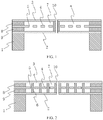
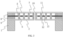
- the MEMS microphone comprises a substrate 1, and a first vibrating diaphragm 3, a second vibrating diaphragm 2 and a back electrode unit, which are formed on the substrate 1.
- the vibrating diaphragms and the back electrode unit of the present invention can be formed on the substrate 1 by means of deposition and etching.
- the substrate 1 can be made of single crystal silicon material, and the vibrating diaphragms and the back electrode unit can be made of single crystal silicon material or polycrystalline silicon material. The selection of such material and the deposition process are well-known to those skilled in the art and will not be described in detail herein.
- the central region of the substrate 1 is provided with a back cavity.
- an insulating layer is arranged in a position where the second vibrating diaphragm 2 and the substrate 1 are connected.
- the insulating layer can be made of silica material well-known to those skilled in the art.
- the back electrode unit of the present invention is a back electrode plate 4 which is provided with a plurality of through holes 5 that penetrate through two sides thereof.
- the back electrode plate 4 is connected to the upper side of the second vibrating diaphragm 2 by means of the supporting of a first support portion 9, such that there is a gap between the back electrode plate 4 and the second vibrating diaphragm 2, which constitutes a capacitor structure.
- the first vibrating diaphragm 3 is connected to the upper side of the back electrode plate 4 by means of the supporting of a second support portion 8, such that there is a gap between the first vibrating diaphragm 3 and the back electrode plate 4, which constitutes a capacitor structure.
- the first support portion 9 and the second support portion 8 are made of an insulating material, and also capable of ensuring the insulation between the two vibrating diaphragms and the back electrode plate while playing a supporting role.
- Such structural form and the selection of materials are well-known to those skilled in the art and will not be described in detail herein.
- the back electrode plate 4 is arranged between the first vibrating diaphragm 3 and the second vibrating diaphragm 2, and the three constitute a sandwich-like structure.
- the two capacitor structures formed above can form a differential capacitor structure to improve the accuracy of the microphone. This is a structural feature of the dual-vibrating-diaphragm microphone and will not be specifically described herein.
- the back electrode plate 4 is arranged in the middle of the space between the first vibrating diaphragm 3 and the second vibrating diaphragm 2. That is to say, the distance from the back electrode plate 4 to the first vibrating diaphragm 3 is equal to the distance from the back electrode plate 4 to the second vibrating diaphragm 2.
- the distances from the back electrode plate 4 to the two vibrating diaphragms may be 0.5-3 ⁇ m respectively, and will not be specifically described again.
- a sealed cavity a is formed between the first vibrating diaphragm 3 and the second vibrating diaphragm 2.
- the first vibrating diaphragm 3 and the second vibrating diaphragm 2 are provided at the upper side and the lower side of the sealed cavity a
- the first support portion 9 and the second support portion 8 are provided at the left side and the right side of the sealed cavity a, which together form the airtight sealed cavity a.
- deposition and etching may be performed by a conventional MEMS process, and then an internal sacrificial layer may be etched away through an etching hole provided on the first vibrating diaphragm 3 to release the first vibrating diaphragm 3 and the second vibrating diaphragm 2. Finally, the etching hole on the first vibrating diaphragm 3 is plugged, so as to form the sealed cavity a.
- the etching hole for etching is provided on the first vibrating diaphragm 3, which is only an example.
- the etching hole can also be provided on the second vibrating diaphragm 2.
- the etching hole may also be provided on the first support portion 9 and the second support portion 8.
- the etching hole can be plugged to form the airtight sealed cavity a.
- a plugging portion may be formed at the edge of the sealed cavity a to plug the etching hole provided at the edge of the sealed cavity a.
- the sealed cavity a separated by the back electrode plate 4 can communicate with each other through the through holes 5.
- the sealed cavity a is filled with a gas whose viscosity coefficient is smaller than that of air.
- the viscosity coefficient expresses the internal friction force caused by the interaction of gas molecules under stress, and is usually related to temperature and pressure. Therefore, the gas whose viscosity coefficient is smaller than that of air is the gas whose viscosity coefficient is smaller than that of air under the same conditions.
- the same conditions may be, for example, within the operating condition range of the microphone, for example, from -20 °C to 100 °C.
- some microphones need to operate in extreme environments, depending on the application fields of the microphone.
- the viscosity coefficient of air ⁇ air 0° C at 0°C is about 1.73 ⁇ 10 -5 Pa ⁇ s
- the viscosity coefficient of hydrogen ⁇ hydrogen 0°C at 0°C is about 0.84 ⁇ 10 -5 Pa ⁇ s, which is far smaller than the viscosity coefficient of air at 0 °C
- the viscosity coefficient of air ⁇ air 20° C is about 1.82 ⁇ 10 -5 Pa ⁇ s
- the viscosity coefficient of hydrogen ⁇ hydrogen 20° C is about 0.88 ⁇ 10 -5 Pa ⁇ s, which is far smaller than the viscosity coefficient of air at 20 °C .
- the sealed cavity a may be filled with hydrogen, such that the gas in the sealed cavity a has a smaller viscosity coefficient, which is equivalent to reducing the acoustic resistance of the two vibrating diaphragms when moving relative to the back electrode, thereby reducing the noise of the microphone.
- gases with lower viscosity coefficients than air. It is possible to select those gases whose viscosity coefficients are smaller than the viscosity coefficient of air under the working conditions of the microphone.
- gases may be, for example, selected from at least one of isobutene, propane, propene, H 2 , ethane, ammonia, acetylene, ethyl chloride, ethylene, CH 3 Cl, methane, SO 2 , H 2 S, chlorine, CO 2 , N 2 O and N 2 .
- the viscosity coefficient of the gas ⁇ is directly related to the acoustic impedance Ra of the microphone.
- the acoustic resistance of the microphone mainly includes the acoustic resistance Ra.gap between gaps between the vibrating diaphragms and the back electrode plate and the acoustic resistance Ra.hole at the through holes of the back electrode plate, wherein:
- Ra.gap 12 ⁇ /( ⁇ n g 3 S mem ) ⁇ (A/2-A 2 /8-lnA/4-3/8); where n is the density of the through holes, g is the size of the gap, S mem is the area of the vibrating diaphragm, and A is the area ratio of the through holes to the back electrode plate.
- Ra.hole 8 ⁇ T/( ⁇ r 4 N ); where T is the thickness of each through hole, r is the radius of each through hole, and N is the total number of the through holes.
- the acoustic resistance Ra of the microphone is Ra.gap + Ra.hole.
- the viscosity coefficient ⁇ of the gas is proportional to the acoustic resistance Ra of the microphone. That is, when the viscosity coefficient ⁇ of the gas in the sealed cavity a is smaller, the acoustic resistance Ra of the microphone is smaller.
- the noise power spectral density PSD (f) of the microphone is proportional to 4KTRa, wherein f is the frequency, K is the Boltzmann's constant and T is the temperature (unit: Kelvin).
- the noise N (amplitude) in the SNR calculation formula is the square root of the weighted integral of the PSD within the desired frequency bandwidth (e.g., 20 Hz-20 kHz). Therefore, the noise N (amplitude) is proportional to the square root of the viscosity coefficient of the gas ⁇ .
- the pressure in the sealed cavity a can be kept to be consistent with the pressure of the external environment.
- sealing can be performed in a hydrogen atmosphere and at room temperature (indoor temperature) and normal pressure (or near one atmospheric pressure) to compensate for the pressure of the external environment. That is to say, the pressure difference between the airtight sealed cavity a and the external environment is zero, so that the first vibrating diaphragm 3 and the second vibrating diaphragm 2 in a static state can be kept flat without the problems of bulging or deflation.
- the pressure in the sealed cavity a after the encapsulation is constant, however, the pressure in the sealed cavity a is enabled to be as close to the pressure of the external environment as possible, for example, the pressure of the sealed cavity a can be selected as one standard atmospheric pressure. Therefore, the pressure difference between the sealed cavity a and the external environment can be minimized so as to reduce the deflection degree of the vibrating diaphragms due to the pressure difference, thereby ensuring the performance (sensitivity) of the microphone.
- the pressure in the sealed cavity a may be different from the pressure in the external environment. This difference is preferably less than 0.5 atm (standard atmospheric pressure), and more preferably less than 0.1 atm (standard atmospheric pressure).
- the support columns 6 may be arranged between the two vibrating diaphragms.
- the support columns 6 pass through the through holes 5 of the back electrode plate 4, and both ends of each of the support columns 6 are respectively connected with the first vibrating diaphragm 3 and the second vibrating diaphragm 2.
- a plurality of support columns 6 may be arranged, which are evenly distributed between the two vibrating diaphragms, such that when there is a pressure difference between the sealed cavity a and the external environment, the support columns 6 connected between the two vibrating diaphragms can resist the deflection of the vibrating diaphragms.
- the pressure difference between the sealed cavity a and the external environment may be caused by the manufacturing process, the pressure difference caused by such process error will not be large. Or when the microphone is in use, the pressure of the external environment thereof will change, but this change will not be large either. Therefore, it is possible to select a small amount of support columns 6, or select support columns 6 with a large aspect ratio, i.e., elongated support columns 6 for supporting. This can significantly improve the acoustic performance (sensitivity) of the microphone compared with the use of a large number of support columns with a small aspect ratio.
- the support columns of the present invention can be made of the same material as the first vibrating diaphragm 3 and/or the second vibrating diaphragm 2.
- the support columns 6 can be formed between the first vibrating diaphragm 3 and the second vibrating diaphragm 2 by layer-by-layer deposition and layer-by-layer etching at the time of deposition, and can be released by subsequent etching, which belongs to the common general knowledge for those skilled in the art and will not be described in detail herein.
- the first vibrating diaphragm 3 and the second vibrating diaphragm 2 are used as one of the electrode plates of the capacitor, it is necessary to adopt a conductive material.
- the support columns 6 are made of the same conductive material as the first vibrating diaphragm 3 and/or the second vibrating diaphragm 2, the first vibrating diaphragm 3 and the second vibrating diaphragm 2 will be short-circuited.
- the back electrode unit needs to adopt a dual-electrode structure.
- the back electrode unit comprises a first back electrode plate 11 for forming one capacitor structure with the first vibrating diaphragm 3, and a second back electrode plate 12 for forming another capacitor structure with the second vibrating diaphragm 2; and an insulating layer 13 is arranged between the first back electrode plate 11 and the second back electrode plate 12.
- the first back electrode plate 11, the insulating layer 13 and the second back electrode plate 12 may be stacked together to form the back electrode unit, which improves the rigidity of the back electrode unit.
- the capacitor consisting of the first vibrating diaphragm 3 and the first back electrode plate 11 is denoted as C1
- the capacitor consisting of the second vibrating diaphragm 2 and the second back electrode plate 12 is denoted as C2
- the capacitor C1 and the capacitor C2 form a differential capacitor structure.
- the support columns 6 may be made of an insulating material to ensure the insulation between the first vibrating diaphragm 3 and the second vibrating diaphragm 2.
- the structure of a single back electrode plate 4 as shown in Fig. 2 may be adopted, which will not be described in detail.
- a pressure relief hole 10 penetrating through the first vibrating diaphragm 3 and the second vibrating diaphragm 2 so as to reduce the acoustic resistance with the external environment and the back cavity when the dual vibrating diaphragms vibrate.
- the hole wall of the pressure relief hole 10, the first vibrating diaphragm 3 and the second vibrating diaphragm 2 define the above-mentioned sealed cavity a, referring to Fig. 1 and Fig. 2 .
- one pressure relief hole 10 which goes through the middle of the first vibrating diaphragm and the middle of the second vibrating diaphragm, may be provided. It is also possible to provide a plurality of pressure relief holes 10, which is distributed in the horizontal direction of the first vibrating diaphragm 3 and the second vibrating diaphragm 2. Each pressure relief hole 10 occupies the volume of the sealed cavity a to separate the pressure relief hole 10 from the sealed cavity a, which will not be described in detail herein.
Landscapes
- Engineering & Computer Science (AREA)
- Physics & Mathematics (AREA)
- Acoustics & Sound (AREA)
- Signal Processing (AREA)
- Multimedia (AREA)
- Health & Medical Sciences (AREA)
- Otolaryngology (AREA)
- Electrostatic, Electromagnetic, Magneto- Strictive, And Variable-Resistance Transducers (AREA)
- Pressure Sensors (AREA)
Applications Claiming Priority (2)
| Application Number | Priority Date | Filing Date | Title |
|---|---|---|---|
| CN201711192077.3A CN107835477B (zh) | 2017-11-24 | 2017-11-24 | 一种mems麦克风 |
| PCT/CN2017/113952 WO2019100432A1 (zh) | 2017-11-24 | 2017-11-30 | 一种mems麦克风 |
Publications (3)
| Publication Number | Publication Date |
|---|---|
| EP3518558A1 true EP3518558A1 (de) | 2019-07-31 |
| EP3518558A4 EP3518558A4 (de) | 2019-07-31 |
| EP3518558B1 EP3518558B1 (de) | 2020-11-04 |
Family
ID=61652602
Family Applications (1)
| Application Number | Title | Priority Date | Filing Date |
|---|---|---|---|
| EP17832031.3A Active EP3518558B1 (de) | 2017-11-24 | 2017-11-30 | Mems-mikrofon |
Country Status (6)
| Country | Link |
|---|---|
| US (1) | US20200204925A1 (de) |
| EP (1) | EP3518558B1 (de) |
| JP (1) | JP6703089B2 (de) |
| KR (1) | KR102128668B1 (de) |
| CN (1) | CN107835477B (de) |
| WO (1) | WO2019100432A1 (de) |
Cited By (1)
| Publication number | Priority date | Publication date | Assignee | Title |
|---|---|---|---|---|
| EP4084498A4 (de) * | 2019-12-27 | 2024-01-24 | Weifang Goertek Microelectronics Co., Ltd. | Mems-chip |
Families Citing this family (33)
| Publication number | Priority date | Publication date | Assignee | Title |
|---|---|---|---|---|
| CN108584863B (zh) * | 2018-04-20 | 2024-07-19 | 杭州士兰集成电路有限公司 | Mems器件及其制造方法 |
| CN108419190B (zh) * | 2018-05-22 | 2024-03-08 | 上饶市经纬自动化科技有限公司 | 一种防御声学攻击的mems惯性传感器及其制作方法 |
| US10771891B2 (en) * | 2018-08-19 | 2020-09-08 | xMEMS Labs, Inc. | Method for manufacturing air pulse generating element |
| US11051109B2 (en) | 2018-09-27 | 2021-06-29 | Taiwan Semiconductor Manufacturing Company, Ltd. | Dual back-plate and diaphragm microphone |
| CN119255168A (zh) | 2018-10-05 | 2025-01-03 | 美商楼氏电子有限公司 | 形成包括褶皱的mems振膜的方法 |
| US11206494B2 (en) | 2018-10-05 | 2021-12-21 | Knowles Electronics, Llc | Microphone device with ingress protection |
| DE112019005007T5 (de) * | 2018-10-05 | 2021-07-15 | Knowles Electronics, Llc | Akustikwandler mit einer Niederdruckzone und Membranen, die eine erhöhte Nachgiebigkeit aufweisen |
| CN109246566B (zh) * | 2018-10-09 | 2020-05-12 | 歌尔股份有限公司 | Mems传感器 |
| CN209897223U (zh) * | 2018-12-31 | 2020-01-03 | 瑞声科技(新加坡)有限公司 | Mems麦克风 |
| CN109831730B (zh) * | 2018-12-31 | 2021-07-09 | 瑞声科技(新加坡)有限公司 | Mems麦克风制造方法 |
| CN209897224U (zh) * | 2018-12-31 | 2020-01-03 | 瑞声科技(新加坡)有限公司 | 一种mems麦克风 |
| CN109714690A (zh) * | 2018-12-31 | 2019-05-03 | 瑞声声学科技(深圳)有限公司 | Mems麦克风 |
| CN110012410A (zh) * | 2018-12-31 | 2019-07-12 | 瑞声科技(新加坡)有限公司 | Mems麦克风制造方法 |
| CN110572762B (zh) * | 2019-09-29 | 2020-11-24 | 潍坊歌尔微电子有限公司 | 一种mems芯片以及电子设备 |
| CN110708649B (zh) * | 2019-09-29 | 2020-12-18 | 潍坊歌尔微电子有限公司 | 一种mems芯片以及电子设备 |
| CN111818434B (zh) * | 2020-06-30 | 2022-03-25 | 歌尔微电子有限公司 | Mems传感器和电子设备 |
| CN113949976B (zh) * | 2020-07-17 | 2022-11-15 | 通用微(深圳)科技有限公司 | 声音采集装置、声音处理设备及方法、装置、存储介质 |
| CN213694144U (zh) * | 2020-12-25 | 2021-07-13 | 歌尔微电子有限公司 | Mems传感器芯片、麦克风和电子设备 |
| CN112887895B (zh) * | 2021-01-26 | 2022-06-07 | 苏州工业园区纳米产业技术研究院有限公司 | 一种调整mems麦克风吸合电压的工艺方法 |
| CN215935099U (zh) * | 2021-10-15 | 2022-03-01 | 苏州敏芯微电子技术股份有限公司 | 微机电结构及其mems麦克风 |
| US12384672B2 (en) * | 2021-12-24 | 2025-08-12 | Aac Acoustic Technologies (Shenzhen) Co., Ltd. | Micro-electro-mechanical system and electro-acoustic conversion device having the micro-electro-mechanical system |
| KR20230115058A (ko) * | 2022-01-26 | 2023-08-02 | 주식회사 디비하이텍 | 맴스 마이크로폰 구조 및 제조방법 |
| US12291445B2 (en) * | 2022-03-16 | 2025-05-06 | Knowles Electronics, Llc | Dual diaphragm dielectric sensor |
| EP4270992A1 (de) * | 2022-04-25 | 2023-11-01 | Infineon Technologies AG | Mems-vorrichtung |
| CN114598979B (zh) * | 2022-05-10 | 2022-08-16 | 迈感微电子(上海)有限公司 | 一种双振膜mems麦克风及其制造方法 |
| CN115065920B (zh) * | 2022-05-26 | 2024-09-10 | 歌尔微电子股份有限公司 | Mems装置和电子设备 |
| CN115159439A (zh) * | 2022-05-26 | 2022-10-11 | 歌尔微电子股份有限公司 | Mems装置和电子设备 |
| CN117319907B (zh) * | 2022-06-21 | 2026-01-06 | 歌尔微电子股份有限公司 | Mems麦克风及麦克风加工工艺 |
| WO2024034321A1 (ja) * | 2022-08-10 | 2024-02-15 | 株式会社オーディオテクニカ | イヤホン |
| US12219336B2 (en) * | 2022-11-23 | 2025-02-04 | Aac Acoustic Technologies (Shenzhen) Co., Ltd. | Sealed dual membrane structure and device including the same |
| CN116239072B (zh) * | 2023-03-29 | 2025-11-25 | 歌尔微电子股份有限公司 | 微机电结构及其制造方法和传感器 |
| CN119172712A (zh) * | 2023-06-20 | 2024-12-20 | 华润微电子控股有限公司 | 一种mems麦克风及其制造方法 |
| WO2025101777A1 (en) * | 2023-11-10 | 2025-05-15 | Vibrant Microsystems Inc. | Foundry-compatible process for a mems audio device |
Family Cites Families (12)
| Publication number | Priority date | Publication date | Assignee | Title |
|---|---|---|---|---|
| JPS5223333Y2 (de) * | 1972-06-17 | 1977-05-27 | ||
| DE102005008511B4 (de) * | 2005-02-24 | 2019-09-12 | Tdk Corporation | MEMS-Mikrofon |
| DE102005016243B3 (de) * | 2005-04-08 | 2006-09-28 | Austriamicrosystems Ag | Mikromechanisches Bauelement, Verfahren zur Herstellung und Verwendung |
| US8796790B2 (en) * | 2008-06-25 | 2014-08-05 | MCube Inc. | Method and structure of monolithetically integrated micromachined microphone using IC foundry-compatiable processes |
| JP6286636B2 (ja) * | 2012-07-19 | 2018-03-07 | 俊 保坂 | センサ・デバイスおよびその製造方法 |
| US8946831B2 (en) * | 2013-03-12 | 2015-02-03 | Invensense, Inc. | Low frequency response microphone diaphragm structures and methods for producing the same |
| US9181080B2 (en) * | 2013-06-28 | 2015-11-10 | Infineon Technologies Ag | MEMS microphone with low pressure region between diaphragm and counter electrode |
| CN103402160B (zh) * | 2013-07-10 | 2016-12-28 | 瑞声声学科技(深圳)有限公司 | Mems麦克风及其工作控制方法 |
| CN103561374A (zh) * | 2013-11-01 | 2014-02-05 | 恩沛音响设备(上海)有限公司 | 驻极体音头壳体入声孔结构及其传声方法 |
| US9438979B2 (en) * | 2014-03-06 | 2016-09-06 | Infineon Technologies Ag | MEMS sensor structure for sensing pressure waves and a change in ambient pressure |
| GB2533410B (en) * | 2014-12-19 | 2017-03-01 | Cirrus Logic Int Semiconductor Ltd | MEMS devices and processes |
| US9828237B2 (en) * | 2016-03-10 | 2017-11-28 | Infineon Technologies Ag | MEMS device and MEMS vacuum microphone |
-
2017
- 2017-11-24 CN CN201711192077.3A patent/CN107835477B/zh active Active
- 2017-11-30 JP JP2018502717A patent/JP6703089B2/ja active Active
- 2017-11-30 EP EP17832031.3A patent/EP3518558B1/de active Active
- 2017-11-30 KR KR1020187001523A patent/KR102128668B1/ko active Active
- 2017-11-30 WO PCT/CN2017/113952 patent/WO2019100432A1/zh not_active Ceased
- 2017-11-30 US US15/751,191 patent/US20200204925A1/en not_active Abandoned
Cited By (1)
| Publication number | Priority date | Publication date | Assignee | Title |
|---|---|---|---|---|
| EP4084498A4 (de) * | 2019-12-27 | 2024-01-24 | Weifang Goertek Microelectronics Co., Ltd. | Mems-chip |
Also Published As
| Publication number | Publication date |
|---|---|
| WO2019100432A1 (zh) | 2019-05-31 |
| JP2020502827A (ja) | 2020-01-23 |
| CN107835477A (zh) | 2018-03-23 |
| EP3518558B1 (de) | 2020-11-04 |
| EP3518558A4 (de) | 2019-07-31 |
| US20200204925A1 (en) | 2020-06-25 |
| CN107835477B (zh) | 2020-03-17 |
| JP6703089B2 (ja) | 2020-06-03 |
| KR20190073309A (ko) | 2019-06-26 |
| KR102128668B1 (ko) | 2020-06-30 |
Similar Documents
| Publication | Publication Date | Title |
|---|---|---|
| EP3518558B1 (de) | Mems-mikrofon | |
| US11159895B2 (en) | Piezoelectric type and capacitive type combined MEMS microphone | |
| CN203661289U (zh) | Mems换能器和电子设备 | |
| KR101096544B1 (ko) | 멤스 마이크로폰 패키지 및 패키징 방법 | |
| GB2576116A (en) | Sensor with vacuum-sealed cavity | |
| TWI659923B (zh) | Mems裝置與製程 | |
| US20190047847A1 (en) | Mems devices and processes | |
| US11496820B2 (en) | MEMS device with quadrilateral trench and insert | |
| CN109714690A (zh) | Mems麦克风 | |
| US11405731B1 (en) | Microelectromechanical system | |
| CN207652676U (zh) | 一种mems麦克风 | |
| CN117319907B (zh) | Mems麦克风及麦克风加工工艺 | |
| US20140353780A1 (en) | Detection structure for a mems acoustic transducer with improved robustness to deformation | |
| US10623852B2 (en) | MEMS devices and processes | |
| US20180288532A1 (en) | Mems device having novel air flow restrictor | |
| JP2006108491A (ja) | 静電容量型センサ及びその製造方法 | |
| TW201334576A (zh) | 麥克風元件及其製造方法 | |
| WO2021056606A1 (zh) | 一种mems芯片以及电子设备 | |
| JP2011244448A (ja) | マイクロエレクトロマシンコンデンサマイクロホン | |
| EP4037336B1 (de) | Mems-chip und elektronische vorrichtung | |
| WO2022006999A1 (zh) | 一种mems麦克风 | |
| EP4054206B1 (de) | Mems-vorrichtung mit tmd-struktur | |
| US20230266356A1 (en) | Dual-operating accelerometer | |
| US10993044B2 (en) | MEMS device with continuous looped insert and trench | |
| CN115931185A (zh) | 一种电容式微机电传感器 |
Legal Events
| Date | Code | Title | Description |
|---|---|---|---|
| STAA | Information on the status of an ep patent application or granted ep patent |
Free format text: STATUS: UNKNOWN |
|
| STAA | Information on the status of an ep patent application or granted ep patent |
Free format text: STATUS: THE INTERNATIONAL PUBLICATION HAS BEEN MADE |
|
| PUAI | Public reference made under article 153(3) epc to a published international application that has entered the european phase |
Free format text: ORIGINAL CODE: 0009012 |
|
| STAA | Information on the status of an ep patent application or granted ep patent |
Free format text: STATUS: THE APPLICATION HAS BEEN PUBLISHED |
|
| A4 | Supplementary search report drawn up and despatched |
Effective date: 20190614 |
|
| AK | Designated contracting states |
Kind code of ref document: A1 Designated state(s): AL AT BE BG CH CY CZ DE DK EE ES FI FR GB GR HR HU IE IS IT LI LT LU LV MC MK MT NL NO PL PT RO RS SE SI SK SM TR |
|
| AX | Request for extension of the european patent |
Extension state: BA ME |
|
| STAA | Information on the status of an ep patent application or granted ep patent |
Free format text: STATUS: REQUEST FOR EXAMINATION WAS MADE |
|
| 17P | Request for examination filed |
Effective date: 20191028 |
|
| RBV | Designated contracting states (corrected) |
Designated state(s): AL AT BE BG CH CY CZ DE DK EE ES FI FR GB GR HR HU IE IS IT LI LT LU LV MC MK MT NL NO PL PT RO RS SE SI SK SM TR |
|
| RIC1 | Information provided on ipc code assigned before grant |
Ipc: H04R 19/00 20060101AFI20200527BHEP Ipc: H04R 19/04 20060101ALI20200527BHEP |
|
| GRAP | Despatch of communication of intention to grant a patent |
Free format text: ORIGINAL CODE: EPIDOSNIGR1 |
|
| STAA | Information on the status of an ep patent application or granted ep patent |
Free format text: STATUS: GRANT OF PATENT IS INTENDED |
|
| RAP1 | Party data changed (applicant data changed or rights of an application transferred) |
Owner name: WEIFANG GOERTEK MICROELECTRONICS CO., LTD. |
|
| INTG | Intention to grant announced |
Effective date: 20200710 |
|
| GRAS | Grant fee paid |
Free format text: ORIGINAL CODE: EPIDOSNIGR3 |
|
| DAV | Request for validation of the european patent (deleted) | ||
| DAX | Request for extension of the european patent (deleted) | ||
| GRAA | (expected) grant |
Free format text: ORIGINAL CODE: 0009210 |
|
| STAA | Information on the status of an ep patent application or granted ep patent |
Free format text: STATUS: THE PATENT HAS BEEN GRANTED |
|
| AK | Designated contracting states |
Kind code of ref document: B1 Designated state(s): AL AT BE BG CH CY CZ DE DK EE ES FI FR GB GR HR HU IE IS IT LI LT LU LV MC MK MT NL NO PL PT RO RS SE SI SK SM TR |
|
| REG | Reference to a national code |
Ref country code: GB Ref legal event code: FG4D |
|
| REG | Reference to a national code |
Ref country code: CH Ref legal event code: EP |
|
| REG | Reference to a national code |
Ref country code: AT Ref legal event code: REF Ref document number: 1332386 Country of ref document: AT Kind code of ref document: T Effective date: 20201115 |
|
| REG | Reference to a national code |
Ref country code: DE Ref legal event code: R096 Ref document number: 602017027088 Country of ref document: DE |
|
| REG | Reference to a national code |
Ref country code: IE Ref legal event code: FG4D |
|
| REG | Reference to a national code |
Ref country code: NL Ref legal event code: MP Effective date: 20201104 |
|
| REG | Reference to a national code |
Ref country code: AT Ref legal event code: MK05 Ref document number: 1332386 Country of ref document: AT Kind code of ref document: T Effective date: 20201104 |
|
| PG25 | Lapsed in a contracting state [announced via postgrant information from national office to epo] |
Ref country code: PT Free format text: LAPSE BECAUSE OF FAILURE TO SUBMIT A TRANSLATION OF THE DESCRIPTION OR TO PAY THE FEE WITHIN THE PRESCRIBED TIME-LIMIT Effective date: 20210304 Ref country code: RS Free format text: LAPSE BECAUSE OF FAILURE TO SUBMIT A TRANSLATION OF THE DESCRIPTION OR TO PAY THE FEE WITHIN THE PRESCRIBED TIME-LIMIT Effective date: 20201104 Ref country code: FI Free format text: LAPSE BECAUSE OF FAILURE TO SUBMIT A TRANSLATION OF THE DESCRIPTION OR TO PAY THE FEE WITHIN THE PRESCRIBED TIME-LIMIT Effective date: 20201104 Ref country code: NO Free format text: LAPSE BECAUSE OF FAILURE TO SUBMIT A TRANSLATION OF THE DESCRIPTION OR TO PAY THE FEE WITHIN THE PRESCRIBED TIME-LIMIT Effective date: 20210204 Ref country code: GR Free format text: LAPSE BECAUSE OF FAILURE TO SUBMIT A TRANSLATION OF THE DESCRIPTION OR TO PAY THE FEE WITHIN THE PRESCRIBED TIME-LIMIT Effective date: 20210205 |
|
| PG25 | Lapsed in a contracting state [announced via postgrant information from national office to epo] |
Ref country code: AT Free format text: LAPSE BECAUSE OF FAILURE TO SUBMIT A TRANSLATION OF THE DESCRIPTION OR TO PAY THE FEE WITHIN THE PRESCRIBED TIME-LIMIT Effective date: 20201104 Ref country code: ES Free format text: LAPSE BECAUSE OF FAILURE TO SUBMIT A TRANSLATION OF THE DESCRIPTION OR TO PAY THE FEE WITHIN THE PRESCRIBED TIME-LIMIT Effective date: 20201104 Ref country code: IS Free format text: LAPSE BECAUSE OF FAILURE TO SUBMIT A TRANSLATION OF THE DESCRIPTION OR TO PAY THE FEE WITHIN THE PRESCRIBED TIME-LIMIT Effective date: 20210304 Ref country code: LV Free format text: LAPSE BECAUSE OF FAILURE TO SUBMIT A TRANSLATION OF THE DESCRIPTION OR TO PAY THE FEE WITHIN THE PRESCRIBED TIME-LIMIT Effective date: 20201104 Ref country code: PL Free format text: LAPSE BECAUSE OF FAILURE TO SUBMIT A TRANSLATION OF THE DESCRIPTION OR TO PAY THE FEE WITHIN THE PRESCRIBED TIME-LIMIT Effective date: 20201104 Ref country code: SE Free format text: LAPSE BECAUSE OF FAILURE TO SUBMIT A TRANSLATION OF THE DESCRIPTION OR TO PAY THE FEE WITHIN THE PRESCRIBED TIME-LIMIT Effective date: 20201104 Ref country code: BG Free format text: LAPSE BECAUSE OF FAILURE TO SUBMIT A TRANSLATION OF THE DESCRIPTION OR TO PAY THE FEE WITHIN THE PRESCRIBED TIME-LIMIT Effective date: 20210204 |
|
| REG | Reference to a national code |
Ref country code: LT Ref legal event code: MG9D |
|
| PG25 | Lapsed in a contracting state [announced via postgrant information from national office to epo] |
Ref country code: HR Free format text: LAPSE BECAUSE OF FAILURE TO SUBMIT A TRANSLATION OF THE DESCRIPTION OR TO PAY THE FEE WITHIN THE PRESCRIBED TIME-LIMIT Effective date: 20201104 |
|
| REG | Reference to a national code |
Ref country code: CH Ref legal event code: PL |
|
| PG25 | Lapsed in a contracting state [announced via postgrant information from national office to epo] |
Ref country code: LU Free format text: LAPSE BECAUSE OF NON-PAYMENT OF DUE FEES Effective date: 20201130 Ref country code: LT Free format text: LAPSE BECAUSE OF FAILURE TO SUBMIT A TRANSLATION OF THE DESCRIPTION OR TO PAY THE FEE WITHIN THE PRESCRIBED TIME-LIMIT Effective date: 20201104 Ref country code: CZ Free format text: LAPSE BECAUSE OF FAILURE TO SUBMIT A TRANSLATION OF THE DESCRIPTION OR TO PAY THE FEE WITHIN THE PRESCRIBED TIME-LIMIT Effective date: 20201104 Ref country code: EE Free format text: LAPSE BECAUSE OF FAILURE TO SUBMIT A TRANSLATION OF THE DESCRIPTION OR TO PAY THE FEE WITHIN THE PRESCRIBED TIME-LIMIT Effective date: 20201104 Ref country code: SM Free format text: LAPSE BECAUSE OF FAILURE TO SUBMIT A TRANSLATION OF THE DESCRIPTION OR TO PAY THE FEE WITHIN THE PRESCRIBED TIME-LIMIT Effective date: 20201104 Ref country code: SK Free format text: LAPSE BECAUSE OF FAILURE TO SUBMIT A TRANSLATION OF THE DESCRIPTION OR TO PAY THE FEE WITHIN THE PRESCRIBED TIME-LIMIT Effective date: 20201104 Ref country code: RO Free format text: LAPSE BECAUSE OF FAILURE TO SUBMIT A TRANSLATION OF THE DESCRIPTION OR TO PAY THE FEE WITHIN THE PRESCRIBED TIME-LIMIT Effective date: 20201104 |
|
| REG | Reference to a national code |
Ref country code: DE Ref legal event code: R097 Ref document number: 602017027088 Country of ref document: DE |
|
| REG | Reference to a national code |
Ref country code: BE Ref legal event code: MM Effective date: 20201130 |
|
| PG25 | Lapsed in a contracting state [announced via postgrant information from national office to epo] |
Ref country code: DK Free format text: LAPSE BECAUSE OF FAILURE TO SUBMIT A TRANSLATION OF THE DESCRIPTION OR TO PAY THE FEE WITHIN THE PRESCRIBED TIME-LIMIT Effective date: 20201104 Ref country code: LI Free format text: LAPSE BECAUSE OF NON-PAYMENT OF DUE FEES Effective date: 20201130 Ref country code: CH Free format text: LAPSE BECAUSE OF NON-PAYMENT OF DUE FEES Effective date: 20201130 Ref country code: MC Free format text: LAPSE BECAUSE OF FAILURE TO SUBMIT A TRANSLATION OF THE DESCRIPTION OR TO PAY THE FEE WITHIN THE PRESCRIBED TIME-LIMIT Effective date: 20201104 |
|
| REG | Reference to a national code |
Ref country code: IE Ref legal event code: MM4A |
|
| PLBE | No opposition filed within time limit |
Free format text: ORIGINAL CODE: 0009261 |
|
| STAA | Information on the status of an ep patent application or granted ep patent |
Free format text: STATUS: NO OPPOSITION FILED WITHIN TIME LIMIT |
|
| 26N | No opposition filed |
Effective date: 20210805 |
|
| PG25 | Lapsed in a contracting state [announced via postgrant information from national office to epo] |
Ref country code: NL Free format text: LAPSE BECAUSE OF FAILURE TO SUBMIT A TRANSLATION OF THE DESCRIPTION OR TO PAY THE FEE WITHIN THE PRESCRIBED TIME-LIMIT Effective date: 20201104 Ref country code: IE Free format text: LAPSE BECAUSE OF NON-PAYMENT OF DUE FEES Effective date: 20201130 Ref country code: AL Free format text: LAPSE BECAUSE OF FAILURE TO SUBMIT A TRANSLATION OF THE DESCRIPTION OR TO PAY THE FEE WITHIN THE PRESCRIBED TIME-LIMIT Effective date: 20201104 Ref country code: IT Free format text: LAPSE BECAUSE OF FAILURE TO SUBMIT A TRANSLATION OF THE DESCRIPTION OR TO PAY THE FEE WITHIN THE PRESCRIBED TIME-LIMIT Effective date: 20201104 |
|
| PG25 | Lapsed in a contracting state [announced via postgrant information from national office to epo] |
Ref country code: SI Free format text: LAPSE BECAUSE OF FAILURE TO SUBMIT A TRANSLATION OF THE DESCRIPTION OR TO PAY THE FEE WITHIN THE PRESCRIBED TIME-LIMIT Effective date: 20201104 |
|
| PG25 | Lapsed in a contracting state [announced via postgrant information from national office to epo] |
Ref country code: IS Free format text: LAPSE BECAUSE OF FAILURE TO SUBMIT A TRANSLATION OF THE DESCRIPTION OR TO PAY THE FEE WITHIN THE PRESCRIBED TIME-LIMIT Effective date: 20210304 Ref country code: TR Free format text: LAPSE BECAUSE OF FAILURE TO SUBMIT A TRANSLATION OF THE DESCRIPTION OR TO PAY THE FEE WITHIN THE PRESCRIBED TIME-LIMIT Effective date: 20201104 Ref country code: MT Free format text: LAPSE BECAUSE OF FAILURE TO SUBMIT A TRANSLATION OF THE DESCRIPTION OR TO PAY THE FEE WITHIN THE PRESCRIBED TIME-LIMIT Effective date: 20201104 Ref country code: CY Free format text: LAPSE BECAUSE OF FAILURE TO SUBMIT A TRANSLATION OF THE DESCRIPTION OR TO PAY THE FEE WITHIN THE PRESCRIBED TIME-LIMIT Effective date: 20201104 |
|
| PG25 | Lapsed in a contracting state [announced via postgrant information from national office to epo] |
Ref country code: MK Free format text: LAPSE BECAUSE OF FAILURE TO SUBMIT A TRANSLATION OF THE DESCRIPTION OR TO PAY THE FEE WITHIN THE PRESCRIBED TIME-LIMIT Effective date: 20201104 |
|
| PG25 | Lapsed in a contracting state [announced via postgrant information from national office to epo] |
Ref country code: BE Free format text: LAPSE BECAUSE OF NON-PAYMENT OF DUE FEES Effective date: 20201130 |
|
| PGFP | Annual fee paid to national office [announced via postgrant information from national office to epo] |
Ref country code: DE Payment date: 20251117 Year of fee payment: 9 |
|
| PGFP | Annual fee paid to national office [announced via postgrant information from national office to epo] |
Ref country code: GB Payment date: 20251126 Year of fee payment: 9 |
|
| PGFP | Annual fee paid to national office [announced via postgrant information from national office to epo] |
Ref country code: FR Payment date: 20251127 Year of fee payment: 9 |