EP3519040B1 - Réglages basés sur un changement de perception dans des prothèses auditives - Google Patents
Réglages basés sur un changement de perception dans des prothèses auditives Download PDFInfo
- Publication number
- EP3519040B1 EP3519040B1 EP17855101.6A EP17855101A EP3519040B1 EP 3519040 B1 EP3519040 B1 EP 3519040B1 EP 17855101 A EP17855101 A EP 17855101A EP 3519040 B1 EP3519040 B1 EP 3519040B1
- Authority
- EP
- European Patent Office
- Prior art keywords
- acoustic
- electro
- hearing prosthesis
- recipient
- acoustic hearing
- Prior art date
- Legal status (The legal status is an assumption and is not a legal conclusion. Google has not performed a legal analysis and makes no representation as to the accuracy of the status listed.)
- Active
Links
Images


Classifications
-
- A—HUMAN NECESSITIES
- A61—MEDICAL OR VETERINARY SCIENCE; HYGIENE
- A61N—ELECTROTHERAPY; MAGNETOTHERAPY; RADIATION THERAPY; ULTRASOUND THERAPY
- A61N1/00—Electrotherapy; Circuits therefor
- A61N1/18—Applying electric currents by contact electrodes
- A61N1/32—Applying electric currents by contact electrodes alternating or intermittent currents
- A61N1/36—Applying electric currents by contact electrodes alternating or intermittent currents for stimulation
- A61N1/36036—Applying electric currents by contact electrodes alternating or intermittent currents for stimulation of the outer, middle or inner ear
- A61N1/36038—Cochlear stimulation
-
- A—HUMAN NECESSITIES
- A61—MEDICAL OR VETERINARY SCIENCE; HYGIENE
- A61B—DIAGNOSIS; SURGERY; IDENTIFICATION
- A61B5/00—Measuring for diagnostic purposes; Identification of persons
- A61B5/12—Audiometering
- A61B5/121—Audiometering evaluating hearing capacity
- A61B5/125—Audiometering evaluating hearing capacity objective methods
-
- A—HUMAN NECESSITIES
- A61—MEDICAL OR VETERINARY SCIENCE; HYGIENE
- A61N—ELECTROTHERAPY; MAGNETOTHERAPY; RADIATION THERAPY; ULTRASOUND THERAPY
- A61N1/00—Electrotherapy; Circuits therefor
- A61N1/02—Details
- A61N1/04—Electrodes
- A61N1/05—Electrodes for implantation or insertion into the body, e.g. heart electrode
- A61N1/0526—Head electrodes
- A61N1/0541—Cochlear electrodes
-
- A—HUMAN NECESSITIES
- A61—MEDICAL OR VETERINARY SCIENCE; HYGIENE
- A61N—ELECTROTHERAPY; MAGNETOTHERAPY; RADIATION THERAPY; ULTRASOUND THERAPY
- A61N1/00—Electrotherapy; Circuits therefor
- A61N1/18—Applying electric currents by contact electrodes
- A61N1/32—Applying electric currents by contact electrodes alternating or intermittent currents
- A61N1/36—Applying electric currents by contact electrodes alternating or intermittent currents for stimulation
- A61N1/36036—Applying electric currents by contact electrodes alternating or intermittent currents for stimulation of the outer, middle or inner ear
-
- H—ELECTRICITY
- H04—ELECTRIC COMMUNICATION TECHNIQUE
- H04R—LOUDSPEAKERS, MICROPHONES, GRAMOPHONE PICK-UPS OR LIKE ACOUSTIC ELECTROMECHANICAL TRANSDUCERS; ELECTRIC HEARING AIDS; PUBLIC ADDRESS SYSTEMS
- H04R25/00—Electric hearing aids
- H04R25/50—Customised settings for obtaining desired overall acoustical characteristics
- H04R25/505—Customised settings for obtaining desired overall acoustical characteristics using digital signal processing
-
- H—ELECTRICITY
- H04—ELECTRIC COMMUNICATION TECHNIQUE
- H04R—LOUDSPEAKERS, MICROPHONES, GRAMOPHONE PICK-UPS OR LIKE ACOUSTIC ELECTROMECHANICAL TRANSDUCERS; ELECTRIC HEARING AIDS; PUBLIC ADDRESS SYSTEMS
- H04R25/00—Electric hearing aids
- H04R25/70—Adaptation of deaf aid to hearing loss, e.g. initial electronic fitting
-
- A—HUMAN NECESSITIES
- A61—MEDICAL OR VETERINARY SCIENCE; HYGIENE
- A61N—ELECTROTHERAPY; MAGNETOTHERAPY; RADIATION THERAPY; ULTRASOUND THERAPY
- A61N1/00—Electrotherapy; Circuits therefor
- A61N1/18—Applying electric currents by contact electrodes
- A61N1/32—Applying electric currents by contact electrodes alternating or intermittent currents
- A61N1/36—Applying electric currents by contact electrodes alternating or intermittent currents for stimulation
- A61N1/36036—Applying electric currents by contact electrodes alternating or intermittent currents for stimulation of the outer, middle or inner ear
- A61N1/36038—Cochlear stimulation
- A61N1/36039—Cochlear stimulation fitting procedures
-
- H—ELECTRICITY
- H04—ELECTRIC COMMUNICATION TECHNIQUE
- H04R—LOUDSPEAKERS, MICROPHONES, GRAMOPHONE PICK-UPS OR LIKE ACOUSTIC ELECTROMECHANICAL TRANSDUCERS; ELECTRIC HEARING AIDS; PUBLIC ADDRESS SYSTEMS
- H04R25/00—Electric hearing aids
- H04R25/55—Electric hearing aids using an external connection, either wireless or wired
- H04R25/554—Electric hearing aids using an external connection, either wireless or wired using a wireless connection, e.g. between microphone and amplifier or using Tcoils
Definitions
- the present invention relates generally to hearing prostheses.
- Hearing loss which may be due to many different causes, is generally of two types, conductive and/or sensorineural.
- Conductive hearing loss occurs when the normal mechanical pathways of the outer and/or middle ear are impeded, for example, by damage to the ossicular chain or ear canal.
- Sensorineural hearing loss occurs when there is damage to the inner ear, or to the nerve pathways from the inner ear to the brain.
- auditory prostheses include, for example, acoustic hearing aids, bone conduction devices, and direct acoustic stimulators.
- sensorineural hearing loss In many people who are profoundly deaf, however, the reason for their deafness is sensorineural hearing loss. Those suffering from some forms of sensorineural hearing loss are unable to derive suitable benefit from auditory prostheses that generate mechanical motion of the cochlea fluid. Such individuals can benefit from implantable auditory prostheses that stimulate nerve cells of the recipient's auditory system in other ways (e.g., electrical, optical and the like). Cochlear implants are often proposed when the sensorineural hearing loss is due to the absence or destruction of the cochlea hair cells, which transduce acoustic signals into nerve impulses. An auditory brainstem stimulator is another type of stimulating auditory prosthesis that might also be proposed when a recipient experiences sensorineural hearing loss due to damage to the auditory nerve.
- US 2012/290045 A1 relates to auditory fitting for multimodal stimulation device and discloses all features in the preamble of claim 1.
- a method comprises: sampling neural activity in response to acoustic stimulation signals and electrical stimulation signals delivered by an electro-acoustic hearing prosthesis worn by a recipient; analyzing the sampled neural activity to determine that the recipient has experienced a sound perception change; and adjusting, based on the sound perception change experienced by the recipient, one or more operations of the electro-acoustic hearing prosthesis to remediate the sound perception change.
- a method comprises: obtaining inner ear responses evoked by stimulation signals at a hearing prosthesis worn by a recipient; objectively identifying, based on an analysis of the obtained inner ear responses, one or more changes in the recipient's perception of sound signals relative to a predetermined perception of sound signals; and adjusting operation of the hearing prosthesis to reverse the one or more changes in a recipient's perception of sound signals.
- a hearing prosthesis comprises: an intra-cochlear stimulating assembly configured to be implanted in a recipient, wherein the intra-cochlear stimulating assembly comprises a plurality of stimulating contacts configured to deliver electrical stimulation signals to the recipient; an acoustic receiver configured to deliver acoustic stimulation signals to the recipient; and one or more processors configured to: sample, via one or more of the stimulating contacts, neural activity of the recipient in response to measurement stimulation signals delivered by the hearing prosthesis, analyze the sampled neural activity to determine that the recipient has experienced a sound perception change, and adjust, based on the sound perception change experienced by the recipient, one or more settings of the electro-acoustic hearing prosthesis used to convert sound signals into the acoustic stimulation signals or the electrical stimulation signals, wherein the one or more settings are adjusted to restore the recipient's sound perception to a predetermined sound perception.
- Auditory/hearing prosthesis recipients suffer from different types of hearing loss (e.g., conductive and/or sensorineural) and/or different degrees/severity of hearing loss.
- hearing loss e.g., conductive and/or sensorineural
- progressive improvements in the design of intra-cochlear electrode arrays (stimulating assemblies), surgical implantation techniques, tooling, etc. have enabled atraumatic surgeries which preserve at least some of the recipient's fine inner ear structures (e.g., cochlea hair cells) and the natural cochlea function, particularly in the lower frequency regions of the cochlea.
- Electro-acoustic hearing prostheses are medical devices that deliver both acoustic stimulation (i.e., acoustic stimulation signals) and electrical stimulation (i.e., electrical stimulation signals), possibly simultaneously, to the same ear of a recipient.
- acoustic stimulation i.e., acoustic stimulation signals
- electrical stimulation i.e., electrical stimulation signals
- the acoustic stimulation is used to present sound signal components corresponding to the lower frequencies of input sound signals (as determined from the residual hearing capabilities of the implanted ear), while the electrical stimulation is used to present sound signal components corresponding to the higher frequencies.
- the tonotopic region of the cochlea where the sound or stimulation output transitions from the acoustic stimulation to the electrical stimulation is called the cross-over frequency region.
- Recipients of electro-acoustic hearing prostheses typically benefit from having the acoustic stimulation in addition to the electrical stimulation, as the acoustic stimulation adds a more "natural" sound to their hearing perception over the electrical stimulation signals only in that ear.
- the addition of the acoustic stimulation can, in some cases, also provide improved pitch and music perception and/or appreciation, as the acoustic signals may contain a more salient lower frequency (e.g., fundamental pitch, F0) representation than is possible with electrical stimulation.
- Other benefits of electro-acoustic hearing prosthesis may include, for example, improved sound localization, binaural release from unmasking, the ability to distinguish acoustic signals in a noisy environment, etc.
- the effectiveness of electro-acoustic and other hearing prostheses generally depends on how well a particular prosthesis is configured or “fitted” to the recipient of the particular prosthesis. For instance, the "fitting" of a hearing prosthesis to a recipient, sometimes also referred to as “programming” or “mapping,” creates a set of configuration settings, parameters, and other data (collectively and generally “settings” herein) that define the specific operational characteristics of the hearing prosthesis. In the case of electro-acoustic hearing prostheses, fitting determines how the prosthesis operates to convert portions (frequencies and/or frequency ranges) of detected sound signals (sounds) into electrical and acoustic stimulation signals.
- the fitting process is used to determine the output levels (e.g., acoustic levels for acoustic simulation and current levels for electrical stimulation), which includes a mapping of received sound signal levels to these various output levels.
- the fitting process for an electro-acoustic hearing prosthesis is used to determine the "cross-over frequency,” which is the frequency/frequency-range where the stimulation output transitions from acoustic stimulation to electrical stimulation.
- a recipient's hearing abilities can change over time. For example, a recipient's residual hearing may gradually decay as he/she ages, a recipient's residual hearing may rapidly deteriorate in response to disease or trauma, etc.
- the recipient's current operational map may be inadequate to represent the sound signals in a manner such that they can be properly perceived/understood by the recipient.
- the recipient's hearing abilities may begin to incorrectly perceive various parts of sound signals due to the fact that the operational map of the hearing prosthesis does not account for the hearing ability changes experienced by the recipient.
- a recipient may notice these sound "perception changes" and contact a hearing professional (e.g., clinician, audiologist, etc.) to conduct a new fitting process to update the operational map.
- a hearing professional e.g., clinician, audiologist, etc.
- a recipient may be unable to detect the perception changes on his/her own.
- young children, new prosthesis recipients, etc. may have substantial difficulty in determining when a perception change occurs.
- the perception change can only be detected within a clinical environment, typically using complex equipment and techniques implemented by trained hearing professionals.
- recipients generally do not visit clinics on a regular basis due to, for example, high costs, low availability of trained audiologists, etc. Therefore, the need to visit a clinic in order to detect a perception change may not only be cost prohibitive for certain recipients, but may also require the recipient to live with the perception change (possibly unknowingly) for a significant period of time before the perception change is identified, let alone addressed.
- a perception change that exist for extended periods of time can lead to negative learning outcomes where the recipient "learns” to perceive certain words, phonemes, or other sounds incorrectly.
- the recipient may have difficulty re-learning to properly perceive/understand the sounds that have been "learned" incorrectly.
- substantially automated techniques that enable an electro-acoustic or other hearing prosthesis implanted in a recipient to use objective measurements to determine when the recipient is likely experiencing sound perception changes.
- the use of objective measurements, rather than subjective measurements, to detect sound perception changes does not require the recipient to actively participate in the detection of the sound perception change.
- the techniques are substantially integrated into the hearing prosthesis and can be performed outside of the clinic setting/environment. As a result, sound perception changes can be detected more rapidly than in conventional arrangements.
- the hearing prosthesis may initiate one or more remedial actions to, for example, address the perception changes.
- the one or more corrective actions may include adjustments to the recipient's operational map to reverse the one or more perception changes.
- embodiments are primarily described herein with reference to one specific type of hearing prosthesis, namely an electro-acoustic hearing prosthesis comprising a cochlear implant portion and a hearing aid portion.
- the techniques presented herein may be used with other types of hearing prostheses, such as bi-modal hearing prostheses, electro-acoustic hearing prosthesis comprising other types of output devices (e.g., auditory brainstem stimulators, direct acoustic stimulators, bone conduction devices, etc .), etc.
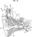
- FIG. 1A is schematic diagram of an exemplary electro-acoustic hearing prosthesis 100 configured to implement embodiments of the present invention
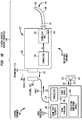
- FIG. 1B is a block diagram of the electro-acoustic hearing prosthesis.
- the electro-acoustic hearing prosthesis 100 includes an external component 102 and an internal/implantable component 104.
- the external component 102 is directly or indirectly attached to the body of the recipient and comprises a sound processing unit 110, an external coil 106, and, generally, a magnet (not shown in FIG. 1A ) fixed relative to the external coil 106.
- the external coil 106 is connected to the sound processing unit 110 via a cable 134.
- the sound processing unit 110 comprises one or more sound input elements 108 (e.g., microphones, audio input ports, cable ports, telecoils, a wireless transceiver, etc.), a sound processor 112, an external transceiver unit (transceiver) 114, a power source 116, and a perception monitoring module 118.
- the sound processing unit 110 may be, for example, a behind-the-ear (BTE) sound processing unit, a body-worn sound processing unit, a button sound processing unit, etc.
- BTE behind-the-ear
- the hearing aid component 141 Connected to the sound processing unit 110 via a cable 135 is a hearing aid component 141.
- the hearing aid component 141 includes a receiver 142 ( FIG. 1B ) that may be, for example, positioned in or near the recipient's outer ear.
- the receiver 142 is an acoustic transducer that is configured to deliver acoustic signals (acoustic stimulation signals) to the recipient via the recipient's ear canal and middle ear.
- FIGs. 1A and 1B illustrate the use of a receiver 142 to deliver acoustic stimulation to the recipient.
- a receiver 142 to deliver acoustic stimulation to the recipient.
- other types of devices may be used in other embodiments to deliver the acoustic stimulation.
- other embodiments may include an external or implanted vibrator that is configured to deliver acoustic stimulation to the recipient.
- the implantable component 104 comprises an implant body (main module) 122, a lead region 124, and an elongate intra-cochlear stimulating assembly 126.
- the implant body 122 generally comprises a hermetically-sealed housing 128 in which an internal transceiver unit (transceiver) 130 and a stimulator unit 132 are disposed.
- the implant body 122 also includes an internal/implantable coil 136 that is generally external to the housing 128, but which is connected to the transceiver 130 via a hermetic feedthrough (not shown in FIG. IB).
- Implantable coil 136 is typically a wire antenna coil comprised of multiple turns of electrically insulated single-strand or multi-strand platinum or gold wire.
- the electrical insulation of implantable coil 136 is provided by a flexible molding (e.g., silicone molding), which is not shown in FIG. 1B .
- a magnet is fixed relative to the implantable coil 136.
- Elongate stimulating assembly 126 is configured to be at least partially implanted in the recipient's cochlea 120 and includes a plurality of longitudinally spaced intra-cochlear electrical stimulating contacts (electrodes) 138 that collectively form a contact array 140 for delivery of electrical stimulation (current) to the recipient's cochlea.
- the contact array 140 may include other types of stimulating contacts, such as optical stimulating contacts, in addition to the electrodes 138.
- Stimulating assembly 126 extends through an opening 121 in the cochlea (e.g., cochleostomy, the round window, etc.) and has a proximal end connected to stimulator unit 132 via lead region 124 and a hermetic feedthrough (not shown in FIG. IB).
- Lead region 124 includes a plurality of conductors (wires) that electrically couple the electrodes 138 to the stimulator unit 132.
- the sound input element(s) 108 are configured to detect/receive input sound signals and to generate electrical output signals therefrom.
- the sound processor 112 is configured execute sound processing and coding to convert the output signals received from the sound input elements into coded data signals that represent acoustical and/or electrical stimulation for delivery to the recipient. That is, as noted, the electro-acoustic hearing prosthesis 100 operates to evoke perception by the recipient of sound signals received by the sound input elements 108 through the delivery of one or both of electrical stimulation signals and acoustic stimulation signals to the recipient.
- the sound processor 112 is configured to convert the output signals received from the sound input elements into a first set of output signals representative of electrical stimulation and/or into a second set of output signals representative of acoustic stimulation.
- the output signals representative of electrical stimulation are represented in FIG. 1B by arrow 115, while the output signals representative of acoustic stimulation are represented in FIG. 1B by arrow 117.
- the output signals 115 are provided to the transceiver 114.
- the transceiver 114 is configured to use the output signals 115 to transcutaneously transfer coded signals to the implantable component 104 via external coil 106. More specifically, the magnets fixed relative to the external coil 106 and the implantable coil 136 facilitate the operational alignment of the external coil 106 with the implantable coil 136. This operational alignment of the coils enables the external coil 106 to transmit the coded data signals, as well as power signals received from power source 116, to the implantable coil 136. In certain examples, external coil 106 transmits the signals to implantable coil 136 via a radio frequency (RF) link.
- RF radio frequency
- FIG. 1B illustrates only one example arrangement.
- IR infrared
- electromagnetic capacitive and inductive transfer
- the coded data and power signals are received at the transceiver 130 and provided to the stimulator unit 132.
- the stimulator unit 132 is configured to utilize the coded data signals to generate electrical stimulation signals (e.g., current signals) for delivery to the recipient's cochlea via one or more stimulating contacts 138.
- electrical stimulation signals e.g., current signals
- electro-acoustic hearing prosthesis 100 electrically stimulates the recipient's auditory nerve cells, bypassing absent or defective hair cells that normally transduce acoustic vibrations into neural activity, in a manner that causes the recipient to perceive one or more components of the received sound signals.
- the cochlea of a hearing prosthesis recipient can be acoustically stimulated upon delivery of a sound signal to the recipient's outer ear.
- the receiver 142 is used to aid the recipient's residual hearing. More specifically, the output signals 117 (i.e., the signals representative of acoustic stimulation) are provided to the receiver 142.
- the receiver 142 is configured to utilize the output signals 117 to generate the acoustic stimulation signals that are provided to the recipient.
- the receiver 142 is used to enhance, and/or amplify a sound signal which is delivered to the cochlea via the middle ear bones and oval window, thereby creating waves of fluid motion of the perilymph within the cochlea.
- the acoustic stimulation signals and the electrical stimulation signals are each generated and delivered to a recipient with a predetermined level and/or loudness in accordance with the operational map that is determined during a fitting process.
- the electro-acoustic hearing prosthesis 100 of FIGs. 1A and 1B includes a perception monitoring module 118 that is configured to use objective measurements to detect/determine changes to a recipient's perception of sound signals and to adjust the recipient's operational map to reverse the perception changes.
- the perception monitoring module 118 in response to detection of a perception change, is configured to automatically adjust, in real-time, one or more operations that control the conversion of sound signals into acoustic stimulation signals and/or the electrical stimulation signals in a manner that ensures the recipient will again perceive sound signals inline with the original perceptions selected in the fitting process. Further details of the perception monitoring module 118 are provided below.
- FIGs. 1A and 1B illustrate an arrangement in which the cochlear implant 100 includes an external component 102.
- embodiments of the present invention may be implemented in hearing prostheses having alternative arrangements.
- the electro-acoustic hearing prosthesis 100 is configured to deliver both acoustic stimulation signals and electrical stimulation signals to a recipient. Acoustic stimulation combined with electrical stimulation is sometimes referred to herein as electro-acoustic stimulation.
- the sound processor 112 is generally configured to execute sound processing and coding, defined by the recipient's operational map, to convert received sound signals into output signals that represent the acoustical or electrical stimulation signals for delivery to the recipient.
- the electrical stimulation signals are generated, from at least a first portion/segment (i.e., frequencies or frequency ranges) of the sound signals, while the acoustic stimulation signals are generated from at least a second portion of the sound signals.
- the recipient's operational map which is determined during a fitting process, dictates how the electro-acoustic hearing prosthesis operates to convert sound signals into acoustic and/or electrical stimulation.
- FIG. 2A illustrates operations of a hearing prosthesis, such as an electro-acoustic hearing prosthesis, to detect and remediate sound perception changes based on objective measurements in accordance with embodiments presented herein. For ease of illustration, FIG. 2A will be described with reference to electro-acoustic hearing prosthesis 100 of FIGs. 1A and 1B .
- FIG. 2A is a flowchart of a method 250 which begins at 252 where the electro-acoustic hearing prosthesis 100 samples, over a period of time, the recipient's neural activity based on acoustic and electrical stimulation. More specifically, the electro-acoustic hearing prosthesis 100 delivers known electrical and/or acoustic stimulation signals, sometimes referred to herein as measurement stimulation signals, to the recipient's auditory system and records resulting inner ear potentials/responses via one or more stimulating contacts 138 and one or more amplifiers 143 ( FIG. 1B ) located in the implantable component 104 (i.e., integrated amplifier of the cochlear implant captures one or more windows of the evoked activity).
- the implantable component 104 i.e., integrated amplifier of the cochlear implant captures one or more windows of the evoked activity.
- the measured inner ear responses which are generally represented in FIG. 1B by arrow 145, are transmitted back to the external component 102 for storage and analysis/evaluation by the perception monitoring module 118.
- the perception monitoring module 118 monitors the inner ear responses evoked by acoustic and/or electrical stimulation via one or more of the stimulating contacts 138.
- inner ear responses or “inner ear potentials” refer to any voltage potential associated with either the electrical properties of the inner ear or its physiological function and/or potentials obtained via measurements at the inner ear.
- Potentials of a physiological nature include acoustically-evoked potentials/responses (e.g., electrocochleography (ECoG) responses) and electrically-evoked potentials/response (e.g., electrically evoked compound action potential (ECAP) responses).
- EoG electrocochleography
- ECAP electrically-evoked compound action potential
- evoked responses are potentials related to the brainstem and auditory cortex, inclusive of the electrical auditory brainstem responses (EABR), the middle latency response, and cortical responses.
- EABR electrical auditory brainstem responses
- cortical responses Potentials of a physiological nature are sometimes referred to herein as "physiological responses.”
- Potentials of electrical nature i.e., potentials relating to the electrical properties of the inner ear itself or intra-cochlear contacts
- Potentials of electrical nature are sometimes referred to herein as "physiological electrical responses.”
- the neural activity is sampled over a period of time and stored within the perception monitoring module 118.
- the neural activity sampling may be performed, for example, periodically, at preselected times, in response to user inputs, etc.
- the neural activity sampling may be conducted either at the start of the day or when the recipient first places the external coil 102 on his/her head.
- the neural activity sampling is conducted at times least invasive to the recipient's listening experience.
- the recipient may be provided with a notification indicating that sampling is about to be performed.
- the sampling may be conducted at sub-clinical levels that cannot be perceived by the recipient.
- the sampling can also be inter-dispersed with the typical operation of the hearing prosthesis such that the inner ear responses and can be obtained at a substantially regular rate.
- the perception monitoring module 118 analyzes the sampled neural activity (i.e., the measured inner ear responses obtained over a period of time) to objectively determine whether the recipient is likely experiencing sound perception changes. In general, to determine whether the recipient is experiencing perception changes, the perception monitoring module 118 is configured to identify and track relative and/or absolute changes in the electrically-evoked responses and/or the acoustically-evoked responses.
- Sound perception changes may be detected, for example, by analyzing measured electrically-evoked responses and acoustically-evoked responses relative to one another, analyzing measured electrically-evoked responses and/or acoustically-evoked responses relative to one or more baseline responses (e.g., determined at fitting, determined based on representative recipient data, etc.).
- baseline responses e.g., determined at fitting, determined based on representative recipient data, etc.
- a particular level of electrical current produces a certain level of neural activity at a first tonotopic location
- a particular level of acoustic stimulation produces a certain level of neural activity at a second tonotopic location.
- an analysis of electrically-evoked reveals that the level of neural activity evoked by the same particular level of electrical current is different (e.g., lower).
- an analysis of acoustically-evoked responses also reveals that the particular level of acoustic stimulation produces a different level of neural activity.
- the perception monitoring module 118 determines that the recipient is likely experiencing a perception change due, for example, to changes in the recipient's residual hearing abilities.
- the objective measurements i.e., inner ear responses
- a subjective quantity i.e., the recipient's perception
- the reliance on objective measurements to infer the subjective quantity eliminates the need for, and reliance on, active recipient participation. This makes the determination less error prone and suitable for children, new recipients, etc.
- the determination of whether the recipient is experiencing perception changes operates as a real-time pattern recognition/matching algorithm that analyzes various combinations of inner ear responses with respect to a database of known relationships between responses and perception changes.
- the inner ear responses may be used as inputs to a pattern matching algorithm that correlates various combinations of the inner ear responses with established patterns indicative of perception changes.
- method 250 returns to 252 where the electro-acoustic hearing prosthesis 100 will continue to sample the neural activity. However, if it is determined at 254 that the recipient is likely experiencing perception changes, then method 250 proceeds to 256 where the perception monitoring module 118 determines one or more adjustments to the recipient's operational map to remediate the sound perception changes. In general, the one or more adjustments are configured so as to return the recipient's perception of sounds to as close as possible to the sound perception set during a most recent fitting process/session and, accordingly, prevent negative learning outcomes. At 258, the one or more adjustments to the recipient's operational map are implemented by the electro-acoustic hearing prosthesis 100.
- Adjustments to a recipient's operational map in order to remediate the perception changes can be made in a number of different manners. In certain examples, only parameters controlling acoustic stimulation (e.g., acoustic stimulation levels) or only the parameters controlling electrical stimulation (e.g., electrical stimulation levels) are adjusted. In other embodiments, both the parameters controlling acoustic stimulation and the parameters controlling electrical stimulation are adjusted.
- the electro-acoustic hearing prosthesis 100 is configured to automatically adjust, in real-time, one or more operations that control the levels (e.g., amplitude) of the acoustical stimulation signals and/or the levels of the electrical stimulation signals, or automatically adjust, in real-time, one or more processing operations that control the perceptual loudness of the acoustical stimulation signals and/or the electrical stimulation signals.
- the perception monitoring module 118 is referred to herein as being configured to adjust the relative level and/or relative loudness of the acoustical stimulation signals to the electrical stimulation signals (i.e., adjust a ratio of the acoustical stimulation signals to the electrical stimulation signals).
- the perception monitoring module 118 may be configured to adjust a "balance" between the acoustical stimulation signals and the electrical stimulation signals.
- adjusting the balance between the acoustical stimulation signals and the electrical stimulation signals refers to corresponding adjustments to both the acoustical stimulation signals and the electrical stimulation signals.
- the adjustments can be made at individual acoustic and/or electrical stimulation channels or across a range of acoustic and/or electrical stimulation channels.
- the adjustments to the operational map may comprise a shift/change in the cross-over frequency defining the transition between acoustic and electrical stimulation.
- neural activity as indicated by inner ear responses, determined in a clinical setting may form a baseline or target defining proper sound perception.
- the one or more adjustments are selected in order to obtain the same responses electric and/or acoustic responses, or a same balance of acoustically-evoked responses to electrically-evoked responses (i.e., effectively same neural perception across both acoustic and electrical hearing).
- negative outcomes can be minimized or reversed.
- FIG. 2A illustrates techniques in accordance with embodiments presented herein where objective responses to acoustic and electrical simulation are used to detect sound perception changes resulting, for example, from residual hearing loss and to determine adjustments to the operation of the hearing prosthesis to remediate the sound perception changes.
- the operational adjustments allow the normalization of the cross-over regions between electrical and acoustic hearing and, accordingly, the acoustic and electrical pathways can be balanced.
- the electro-acoustic hearing prosthesis 100 operates to monitor the invoked responses to acoustic and electrical stimulation, track these responses over time, and to dynamically re-balance, in real-time, in response to identified changes, as needed.
- both acoustically-evoked and electrically-evoked responses allows the electro-acoustic hearing prosthesis 100 to compare the relative acoustic and electrical levels, and, as a result, may not be mislead by natural mutual variations due to the time of a day, drug usage, etc.
- FIG. 2B is a flowchart illustrating method 250 of FIG. 2A implemented as part of a larger method 270.
- method 270 of FIG. 2B will again be described with reference to electro-acoustic hearing prosthesis 100 of FIGs. 1A and 1B .
- the method 270 begins at 272 where a clinical fitting process is performed, as described above, to determine the recipient's operational map.
- the parameters forming the recipient's operational map, as well as recipient-specific attributes are collected and stored in a centralized database 275.
- the centralized database 275 is a collection of data obtained from real or hypothetical recipient fitting sessions and subsequent perception monitoring sessions described herein.
- the information about different recipients may be used to form "recipient groups.” Each of these recipient groups represents a subset of information that is linked in some manner, such as by operational map settings, recipient-specific attributes, etc.
- the centralized database 275 is part of a cloud environment.
- the recipient of the electro-acoustic hearing prosthesis 100 is associated with one or more of the recipient groups based on, for example, the recipient's attributes, the recipient's clinically determined operational map settings, etc.
- the association between the recipient and then one or more recipient groups may also be stored in the centralized database 275.
- the clinically determined operational map is placed in use by the electro-acoustic hearing prosthesis 100 to convert sound signals into acoustic and/or electric stimulation.
- the electro-acoustic hearing prosthesis 100 also implements process 250 as described above.
- the electro-acoustic hearing prosthesis 100 samples, over a period of time, the recipient's neural activity based on acoustic and electrical stimulation (i.e., receives and stores inner ear responses evoked by acoustic and/or electrical stimulation via one or more of the stimulating contacts 138).
- the inner ear responses may include physiological potentials, such as acoustically-evoked potentials (i.e., an ECoG response) and electrically-evoked potentials (e.g., ECAP, EABR, stapedial reflex threshold (ESRT), etc.), and/or physiological electrical potentials (e.g., EVT, impedances, etc.).
- physiological potentials such as acoustically-evoked potentials (i.e., an ECoG response) and electrically-evoked potentials (e.g., ECAP, EABR, stapedial reflex threshold (ESRT), etc.
- physiological electrical potentials e.g., EVT, impedances, etc.
- the perception monitoring module 118 analyzes the sampled neural activity to objectively determine perception changes that the recipient may be experiencing. If it is determined at 254 that the recipient is not experiencing perception changes, then the method returns to 252 where the electro-acoustic hearing prosthesis 100 will continue to sample the neural activity. However, if it is determined at 254 that the recipient is likely experiencing perception changes, then the method proceeds to 256 where the perception monitoring module 118 determines one or more adjustments to the recipient's operational map to remediate the perception changes. In the example of FIG. 2B , the determination of the one or more adjustments may optionally make use of data from the centralized database 275.
- the perception monitoring module 118 may compare or otherwise correlate the detected changes in the inner ear responses to changes experienced by similarly situated recipients (e.g., other recipients in the recipient group or groups with which the recipient has been associated) to determine how the perception change could be effectively remediated. In certain embodiments, this correlation may also reveal other information, such as a likely cause of the perception change. As shown, at 282 the results of the one or more adjustments can be used to update the centralized database 275.
- the one or more adjustments to the recipient's operational map are implemented by the electro-acoustic hearing prosthesis 100.
- a determination is made as whether or not the adjustments warrant clinical intervention (i.e., are the adjustments excessive/significant). If it is determined at 278 that the one or more adjustments do not warrant clinical intervention, then the method returns to 252. However, if it is determined at 278 that the one or more adjustments are sufficient to warrant clinical intervention, the electro-acoustic hearing prosthesis 100 may initiate the clinical intervention at 280.
- the electro-acoustic hearing prosthesis 100 may initiate the clinical intervention by, for example, generating an audible or visible notification to the recipient via the sound processing unit or some associated device, sending a notification to a clinic or other external party, etc.
- FIG. 2B illustrates the operations of 278 and 280 occurring after the operations of 258, it is to be appreciated that this is merely illustrative and that the determination of 278 could be performed before implementing the one or more adjustments.
- the electro-acoustic hearing prosthesis 100 may continue to operate using the prior operational map until the recipient is able to receive the clinical intervention.
- FIGs. 3A, 3B , 4A, and 4B illustrate specific example applications of the techniques presented herein.
- FIGs. 3A and 3B shown are graphs that each have a vertical (Y) axis representing increasing inner ear response levels, and a horizontal (X) axis representing increasing frequency.
- Each of the graphs in FIGs. 3A and 3B also includes a first section 360 that corresponds to acoustic stimulation, and a second section 362 that corresponds to electrical stimulation. That is, section 360 generally represents the levels of inner ear responses and frequencies associated with the acoustic stimulation signals, while section 362 generally represents the levels of inner ear responses and frequencies associated with the electrical stimulation signals.
- acoustic and electrical stimulation may evoke different types of inner ear responses that have different "levels.”
- the acoustically-evoked inner response levels and the electrically-evoked inner ear response levels have been normalized for collective representation by the vertical axis in FIGs. 3A and 3B .
- FIG. 3A illustrates levels of inner ear responses, for respective frequencies, that are determined in a clinical (e.g., initial) fitting process. That is, as noted above, an operational map is clinically determined for a recipient. This operational map is used by the electro-acoustic hearing prosthesis 100 to convert sound signals of a given frequency to stimulation (either acoustic or electrical), which then evokes the levels of inner ear responses shown in FIG. 3A.
- FIG. 3A also schematically illustrates a cross-over frequency 364 where the stimulation transitions from acoustic to electrical stimulation (i.e., the divide between sections 360 and 362).
- the cross-over frequency 364 is shown as a discrete point where acoustic stimulation ends and electrical stimulation begins.
- acoustic and electrical stimulation may overlap within a range of frequencies at or near the cross-over frequency 364.
- FIG. 3B illustrates an example in which the electro-acoustic hearing prosthesis 100 determines that the recipient is likely experiencing perception changes due to a decay in the neural activity across a range of acoustic frequencies (i.e., across the tonotopic region of the cochlea associated with acoustic hearing). That is, as shown in section 360 of FIG. 3B , the levels of the inner ear responses measured by the electro-acoustic hearing prosthesis 100 drop across the entirety of the acoustic hearing frequency range.
- the decay in the neural activity within the acoustic region indicates that the recipient's residual hearing has declined, either permanently or temporarily, due to, for example, disease, trauma, etc.
- the electro-acoustic hearing prosthesis 100 detects over a period of time (e.g., several days, weeks, or months) that the inner ear responses generated in response to acoustic stimulation have decayed relative to those obtained in response to electrical stimulation.
- a period of time e.g., several days, weeks, or months
- an input sound pressure level (SPL) of 20 dB-HL delivered at the 3 kHz region produces a neural response at 40uV
- acoustic stimulation delivered at the 1 kHz region at the same sound input level of 20dB-HL produces a neural response at 20uV.
- the electro-acoustic hearing prosthesis 100 detects that the neural response activity evoked by the acoustic stimulation at the 20dB-HL input level delivered at the 1kHz region has dropped relative to the neural response activity being produced by the electrical stimulation at the 20 dB-HL delivered at the 3 kHz region.
- the electro-acoustic hearing prosthesis 100 determines that the recipient is likely experiencing a perception change. The electro-acoustic hearing prosthesis 100 may then make adjustments to the recipient's operational map to remediate the perception change. In one embodiment, the electro-acoustic hearing prosthesis 100 compensates by increasing the gain applied to the acoustic channels to re-balance the neural response levels. The electro-acoustic hearing prosthesis 100 may also notify/alert a clinician/audiologist of the changes.
- the electro-acoustic hearing prosthesis 100 compares measured inner ear responses with a centralized database in order to classify the observed trends against known patterns/recipient groups.
- the electro-acoustic hearing prosthesis 100 operates to prevent negative learning outcomes during this time, whereby the brain becomes attuned to hearing without the fill content of the lower frequencies (i.e., prevent the brain from training itself not use the content at these frequencies, which would limit future learning outcomes).
- the electro-acoustic hearing prosthesis 100 continues to monitor the inner ear responses.
- the acoustically-evoked responses may permanently decline or, in certain cases, may improve and return to the prior levels (e.g., recovery from an illness).
- FIGs. 4A and 4B shown are graphs that each has a vertical (Y) axis representing increasing inner ear response levels, and a horizontal (X) axis representing increasing frequency.
- the graphs in FIGs. 4A and 4B also include a first section 460 that corresponds to acoustic stimulation, and a second section 462 that corresponds to electrical stimulation. Similar to FIGs. 3A and 3B , for ease of illustration the acoustically-evoked inner response levels and the electrically-evoked inner ear response levels have been normalized for collective representation by the vertical axis in FIGs. 4A and 4B .
- FIG. 4A illustrates an example in which the electro-acoustic hearing prosthesis 100 determines that a recipient is likely experiencing perception changes due to a significant drop in neural activity evoked in response to acoustic stimulation just below the cross-over frequency 464 (i.e., the divide between acoustic and electrical stimulation).
- the neural response activity begins to drop significantly at 2 kHz, but is normal at lower acoustic frequencies.
- the electro-acoustic hearing prosthesis 100 then makes adjustments to the recipient's operational map to remediate the perception change or changes.
- the electro-acoustic hearing prosthesis 100 compensates by re-organizing the frequency bands so that the frequencies at which the neural response has dropped will be covered by electrical stimulation. That is, as shown by arrow 465 in FIG.
- the electro-acoustic hearing prosthesis 100 adjusts the recipient's operational map to shift the cross-over frequency 464 lower, thereby lengthening the tonotopic region covered by electrical stimulation and shortening the tonotopic region covered by acoustic stimulation.
- This downward shift in the cross-over frequency 464 prevents the recipient from experiencing a gap in his/her frequency perception which, over time, can result in negative learning outcomes.
- the examples of FIGs. 3A-3B and 4A-4B are merely illustrative and that the techniques presented herein may detect a number of different types of perception changes and make a number of different types of adjustments.
- the electrically-evoked inner ear response levels may fluctuate differently from the acoustically-evoked levels due to, for example, tissue hardening (e.g., the electro-acoustic hearing prosthesis 100 detects a reduction in the electrically-evoked inner ear response levels).
- the electro-acoustic hearing prosthesis 100 adjusts the recipient's operational map to increase the electrical stimulation current levels.
- the electro-acoustic hearing prosthesis 100 may query a centralized database regarding, for example, the age of implementation of the recipient to determine whether the neural activity behavior is normal/expected. This information can be used in different manners, including in selection of the adjustments to the recipient's operational map.
- the recipient may suffer from a disease/illness that causes increased sensitivity in the acoustic region (i.e., increased levels of acoustically-evoked inner ear responses).
- the electro-acoustic hearing prosthesis 100 may query a centralized database to see if the measured inner ear responses can be correlated to any known disease. If this query is successful (i.e. correlates the recipient's measured inner ear responses with a known disease), the query may also return a strategy for adjustments to the recipient's operational map.
- the electro-acoustic hearing prosthesis 100 temporarily reduces the acoustic stimulation level, monitors the situation, and notifies a hearing professional or other medical practitioner of the possible occurrence and affects of the disease.
- the electro-acoustic hearing prosthesis 100 detects an increase in the level of acoustically-evoked inner ear responses relative to the electrically-evoked responses, and the electro-acoustic hearing prosthesis 100 queries a centralized database to determine if the measured inner ear responses can be correlated to any known disease.
- the measured inner response trends cannot be correlated to any known behavior and the electro-acoustic hearing prosthesis 100 or other entity (e.g., a centralized system) notifies a medical practitioner.
- the medical practitioner analyses the trend/pattern, makes a diagnosis, and selects an operational map adjustment strategy. If/when the operational map adjustment strategy is validated, the strategy can then be uploaded into the centralized database for subsequent use by other prostheses, clinics, etc.
- FIG. 5 is a schematic block diagram illustrating an arrangement for a sound processing unit, such as sound processing unit 110, in accordance with an embodiment of the present invention.
- the sound processing unit 110 includes one or more processors 584 and a memory 585.
- the memory 585 includes sound processor logic 586, perception monitoring logic 588, and a data store 590.
- the memory 585 may be read only memory (ROM), random access memory (RAM), or another type of physical/tangible memory storage device.
- the memory 585 may comprise one or more tangible (non-transitory) computer readable storage media (e.g., a memory device) encoded with software comprising computer executable instructions and when the software is executed (by the one or more processors 584) it is operable to perform the operations described herein with reference to the sound processor 112 and the perception monitoring module 118.
- FIG. 5 illustrates software implementations for the sound processor 112 and the perception monitoring module 118.
- one or more operations associated with the sound processor 112 and the perception monitoring module 118 may be partially or fully implemented with digital logic gates in one or more application-specific integrated circuits (ASICs).
- ASICs application-specific integrated circuits
- the perception monitoring module 118 has been shown and described as elements that are separate from the sound processor 112. It is to be appreciated that the functionality of the perception monitoring module 118 may be incorporated into the sound processor 112.
- embodiments presented herein are directed to techniques enabling an electro-acoustic or other type of hearing prosthesis to objectively determine that a recipient is experiencing changes to how he/she is perceiving sounds (perception changes).
- the use of objective measurements, rather than subjective measurements, to detect perception changes does not require the recipient to actively participate in the detection of the perception change.
- the electro-acoustic hearing prosthesis may immediately initiate one or more corrective actions to address the perception changes.
- the one or more corrective actions may include adjustments to the recipient's operational map to reverse the one or more perception changes in order to prevent negative learning outcomes.
- the techniques presented herein may, for example, provide developmental benefits, physiological benefits, assist in disease identification and understanding, etc.
- hearing prosthesis namely an electro-acoustic hearing prosthesis comprising a cochlear implant portion and a hearing aid portion.
- the techniques presented herein may be used with other types of hearing prostheses, such as bi-modal hearing prostheses, electro-acoustic hearing prosthesis comprising other types of output devices (e.g., auditory brainstem stimulators, direct acoustic stimulators, bone conduction devices, etc.)
- output devices e.g., auditory brainstem stimulators, direct acoustic stimulators, bone conduction devices, etc.
Landscapes
- Health & Medical Sciences (AREA)
- Engineering & Computer Science (AREA)
- Otolaryngology (AREA)
- Life Sciences & Earth Sciences (AREA)
- General Health & Medical Sciences (AREA)
- Physics & Mathematics (AREA)
- Public Health (AREA)
- Biomedical Technology (AREA)
- Veterinary Medicine (AREA)
- Animal Behavior & Ethology (AREA)
- Acoustics & Sound (AREA)
- Nuclear Medicine, Radiotherapy & Molecular Imaging (AREA)
- Radiology & Medical Imaging (AREA)
- Heart & Thoracic Surgery (AREA)
- Audiology, Speech & Language Pathology (AREA)
- Signal Processing (AREA)
- Neurosurgery (AREA)
- Surgery (AREA)
- Pathology (AREA)
- Medical Informatics (AREA)
- Molecular Biology (AREA)
- Biophysics (AREA)
- Multimedia (AREA)
- Cardiology (AREA)
- Prostheses (AREA)
- Neurology (AREA)
- Computer Networks & Wireless Communication (AREA)
Claims (12)
- Prothèse auditive électro-acoustique (100), comprenant :un ensemble stimulation intra-cochléaire (126) conçu pour être implanté chez un bénéficiaire, l'ensemble stimulation intra-cochléaire (126) comprenant une pluralité de contacts de stimulation (138) conçus pour administrer des signaux de stimulation électrique au bénéficiaire ; etun récepteur acoustique (142) conçu pour délivrer des signaux de stimulation acoustique au bénéficiaire ;caractérisée parun ou plusieurs processeurs (112) conçus pour :échantillonner, via un ou plusieurs contacts de stimulation (138), l'activité neuronale du bénéficiaire en réponse aux signaux de stimulation de mesure délivrés par la prothèse auditive électro-acoustique (100),analyser l'activité neuronale échantillonnée pour déterminer que le bénéficiaire a expérimenté un changement de perception sonore, etajuster, sur la base du changement de perception sonore expérimenté par le bénéficiaire, un ou plusieurs paramétrages de la prothèse auditive électro-acoustique (100) utilisée pour convertir les signaux sonores en signaux de stimulation acoustique ou signaux de stimulation électrique, les un ou plusieurs paramétrages étant ajustés pour restaurer la perception sonore du bénéficiaire vers une perception sonore prédéterminée.
- Prothèse auditive électro-acoustique (100) selon la revendication 1, l'ensemble stimulation intra-cochléaire (126) et le un ou plusieurs processeurs (112) faisant partie d'un composant implantable (104) de la prothèse auditive électro-acoustique (100).
- Prothèse auditive électro-acoustique (100) selon la revendication 1 ou 2, le un ou plusieurs processeurs (112) faisant partie d'un composant externe (102) de la prothèse auditive électro-acoustique (100).
- Prothèse auditive électro-acoustique (100) selon la revendication 1, 2 ou 3, pour ajuster un ou plusieurs paramétrages de la prothèse auditive électro-acoustique (100), le un ou plusieurs processeurs (112) étant conçus pour :
ajuster un rapport des signaux de stimulation acoustique utilisés pour évoquer la perception des signaux sonores par rapport aux signaux de stimulation électrique utilisés pour évoquer la perception des signaux sonores. - Prothèse auditive électro-acoustique (100) selon l'une des revendications 1 à 4, pour ajuster un ou plusieurs paramétrages de la prothèse auditive électro-acoustique (100), le un ou plusieurs processeurs (112) étant conçus pour :
ajuster au moins l'un d'un niveau ou d'un volume de perception des signaux de stimulation acoustique par rapport aux signaux de stimulation électrique. - Prothèse auditive électro-acoustique (100) selon l'une des revendications précédentes, afin d'ajuster un ou plusieurs paramétrages de la prothèse auditive électro-acoustique (100), le un ou plusieurs processeurs (112) étant conçus pour :
ajuster une fréquence croisée à laquelle la prothèse auditive électro-acoustique (100) effectue une transition depuis la délivrance de signaux de stimulation acoustique vers la délivrance de signaux de stimulation électrique. - Prothèse auditive électro-acoustique (100) selon l'une des revendications précédentes, pour échantillonner l'activité neuronale du bénéficiaire en réponse aux signaux de stimulation de mesure délivrés par la prothèse auditive (100) portée par un bénéficiaire, le un ou plusieurs processeurs (112) étant conçus pour :
obtenir une pluralité de réponses acoustiquement évoquées et une pluralité de réponses électriquement évoquées sur une période de temps. - Prothèse auditive électro-acoustique (100) selon l'une des revendications précédentes, pour ajuster un ou plusieurs paramétrages de la prothèse auditive électro-acoustique (100), le un ou plusieurs processeurs (112) étant conçus pour :
corréler l'activité neuronale échantillonnée à l'activité neuronale prédéterminée qui est spécifique du bénéficiaire. - Prothèse auditive électro-acoustique (100) selon l'une des revendications précédentes, pour ajuster un ou plusieurs paramétrages de la prothèse auditive électro-acoustique (100), le un ou plusieurs processeurs (112) étant conçus pour :
exécuter un processus de correspondance de profil en temps réel qui corrèle l'activité neuronale échantillonnée par rapport à une base de données de relations connues entre l'activité neuronale et les changements fonctionnels de la prothèse auditive électro-acoustique. - Prothèse auditive électro-acoustique (100) selon l'une des revendications précédentes, pour échantillonner l'activité neuronale en réponse aux signaux de stimulation acoustique et aux signaux de stimulation électrique délivrés par une prothèse auditive électro-acoustique portée par un bénéficiaire, le un ou plusieurs processeurs étant conçus pour :
obtenir une pluralité de réponses acoustiquement évoquées et une pluralité de réponses électriquement évoquées sur une période de temps. - Prothèse auditive électro-acoustique (100) selon l'une des revendications précédentes, le un ou plusieurs processeurs (112) étant en outre conçus pour :
déclencher au moins l'une d'une alerte audible ou visuelle indicatrice du changement de perception sonore. - Prothèse auditive électro-acoustique (100) selon l'une des revendications précédentes, le un ou plusieurs processeurs (112) étant en outre conçus pour :
envoyer une alerte de changement de perception à une localisation distante, l'alerte de changement de perception étant indicatrice du changement de perception sonore.
Applications Claiming Priority (2)
| Application Number | Priority Date | Filing Date | Title |
|---|---|---|---|
| US15/278,464 US10194814B2 (en) | 2016-09-28 | 2016-09-28 | Perception change-based adjustments in hearing prostheses |
| PCT/IB2017/055801 WO2018060828A1 (fr) | 2016-09-28 | 2017-09-25 | Réglages basés sur un changement de perception dans des prothèses auditives |
Publications (3)
| Publication Number | Publication Date |
|---|---|
| EP3519040A1 EP3519040A1 (fr) | 2019-08-07 |
| EP3519040A4 EP3519040A4 (fr) | 2020-04-29 |
| EP3519040B1 true EP3519040B1 (fr) | 2021-07-28 |
Family
ID=61688185
Family Applications (1)
| Application Number | Title | Priority Date | Filing Date |
|---|---|---|---|
| EP17855101.6A Active EP3519040B1 (fr) | 2016-09-28 | 2017-09-25 | Réglages basés sur un changement de perception dans des prothèses auditives |
Country Status (3)
| Country | Link |
|---|---|
| US (5) | US10194814B2 (fr) |
| EP (1) | EP3519040B1 (fr) |
| WO (1) | WO2018060828A1 (fr) |
Families Citing this family (11)
| Publication number | Priority date | Publication date | Assignee | Title |
|---|---|---|---|---|
| AU2017289971B2 (en) * | 2016-06-30 | 2019-08-22 | Med-El Elektromedizinische Geraete Gmbh | Bio-inspired fast fitting of cochlear implants |
| US10194814B2 (en) * | 2016-09-28 | 2019-02-05 | Cochlear Limited | Perception change-based adjustments in hearing prostheses |
| US11253193B2 (en) * | 2016-11-08 | 2022-02-22 | Cochlear Limited | Utilization of vocal acoustic biomarkers for assistive listening device utilization |
| US11813460B2 (en) * | 2018-07-25 | 2023-11-14 | Cochlear Limited | Individualized adaptation of medical prosthesis settings |
| CN115999047A (zh) * | 2018-09-14 | 2023-04-25 | 科利耳有限公司 | 一种包括植入式假体的植入式部件的装置 |
| EP3902594B1 (fr) * | 2018-12-28 | 2024-11-20 | Advanced Bionics AG | Systèmes de surveillance de réponses évoquées apparaissant lors d'une procédure d'insertion d'un fil d'électrode |
| CN113490524B (zh) * | 2019-06-17 | 2024-08-23 | 科利耳有限公司 | 音频设备的接受者的音乐感知的改善 |
| EP4628011A3 (fr) * | 2019-11-07 | 2025-12-24 | Cochlear Limited | Procédé de détection d'une pluralité d'états de santé d'une cochlée |
| EP4115943B1 (fr) * | 2021-07-05 | 2023-11-22 | Advanced Bionics AG | Système de prothèse auditive |
| EP4387270A1 (fr) * | 2022-12-12 | 2024-06-19 | Sonova AG | Fonctionnement d'un dispositif auditif pour aider l'utilisateur à venir dans un style de vie sain |
| WO2024194760A1 (fr) * | 2023-03-20 | 2024-09-26 | Cochlear Limited | Commande de stimulation électro-acoustique |
Family Cites Families (21)
| Publication number | Priority date | Publication date | Assignee | Title |
|---|---|---|---|---|
| US8086319B2 (en) | 2004-05-10 | 2011-12-27 | Cochlear Limited | Cochlear implant fitting |
| US8265765B2 (en) | 2005-12-08 | 2012-09-11 | Cochlear Limited | Multimodal auditory fitting |
| WO2007134048A2 (fr) | 2006-05-08 | 2007-11-22 | Cochlear Americas | RÉglage automatisÉ de prothÈse auditive |
| US8825149B2 (en) * | 2006-05-11 | 2014-09-02 | Northwestern University | Systems and methods for measuring complex auditory brainstem response |
| US8165687B2 (en) | 2008-02-26 | 2012-04-24 | Universidad Autonoma Metropolitana, Unidad Iztapalapa | Systems and methods for detecting and using an electrical cochlear response (“ECR”) in analyzing operation of a cochlear stimulation system |
| EP2262459A4 (fr) * | 2008-04-03 | 2011-04-06 | Med El Elektromed Geraete Gmbh | Mesure de diagnostic synchronisée pour implants cochléaires |
| EP2140908B1 (fr) * | 2008-07-02 | 2016-10-19 | Cochlear Limited | Dispositifs pour personnes dont l'audition est altérée |
| US8751006B2 (en) | 2008-12-23 | 2014-06-10 | Advanced Bionics Ag | Channel-specific adjustment of sound processing strategies based on electrode impedance |
| US9155886B2 (en) | 2010-10-28 | 2015-10-13 | Cochlear Limited | Fitting an auditory prosthesis |
| EP2827945A1 (fr) | 2012-03-22 | 2015-01-28 | Advanced Bionics AG | Systèmes de programmation pour provoquer des réponses évoquées chez un patient portant un implant cochléaire et exécuter des actions prédéterminées en fonction des réponses évoquées |
| EP2943246B1 (fr) * | 2013-01-11 | 2017-03-29 | Advanced Bionics AG | Système pour stimulation d'écoute neurale |
| US9656071B2 (en) | 2013-03-15 | 2017-05-23 | Cochlear Limited | Control for hearing prosthesis fitting |
| US8843217B1 (en) * | 2013-09-13 | 2014-09-23 | Lockheed Martin Corporation | Combined vestibular and cochlear implant and method |
| WO2015077786A1 (fr) * | 2013-11-25 | 2015-05-28 | Massachusetts Eye & Ear Infirmary | Capteurs piézoélectriques pour prothèses auditives |
| US20150237452A1 (en) * | 2014-02-14 | 2015-08-20 | Filiep Vanpoucke | Systems and methods for fitting an auditory prosthesis |
| EP2919483B1 (fr) * | 2014-03-11 | 2019-05-08 | Oticon Medical A/S | Système d'assistance auditive bilatérale et procédé d'adaptation d'un tel système |
| US10225671B2 (en) * | 2016-05-27 | 2019-03-05 | Cochlear Limited | Tinnitus masking in hearing prostheses |
| US10091591B2 (en) * | 2016-06-08 | 2018-10-02 | Cochlear Limited | Electro-acoustic adaption in a hearing prosthesis |
| US10292644B2 (en) * | 2016-06-21 | 2019-05-21 | Cochlear Limited | Automated inner ear diagnoses |
| US10357656B2 (en) * | 2016-07-12 | 2019-07-23 | Cochlear Limited | Hearing prosthesis programming |
| US10194814B2 (en) * | 2016-09-28 | 2019-02-05 | Cochlear Limited | Perception change-based adjustments in hearing prostheses |
-
2016
- 2016-09-28 US US15/278,464 patent/US10194814B2/en active Active
-
2017
- 2017-09-25 EP EP17855101.6A patent/EP3519040B1/fr active Active
- 2017-09-25 WO PCT/IB2017/055801 patent/WO2018060828A1/fr not_active Ceased
-
2018
- 2018-12-11 US US16/215,828 patent/US10905343B2/en active Active
-
2020
- 2020-12-23 US US17/132,478 patent/US11723572B2/en active Active
-
2023
- 2023-06-23 US US18/340,176 patent/US12453499B2/en active Active
-
2025
- 2025-10-10 US US19/355,305 patent/US20260041348A1/en active Pending
Also Published As
| Publication number | Publication date |
|---|---|
| US11723572B2 (en) | 2023-08-15 |
| US12453499B2 (en) | 2025-10-28 |
| US10194814B2 (en) | 2019-02-05 |
| US20180085581A1 (en) | 2018-03-29 |
| US20190104957A1 (en) | 2019-04-11 |
| US20260041348A1 (en) | 2026-02-12 |
| EP3519040A4 (fr) | 2020-04-29 |
| US20230329614A1 (en) | 2023-10-19 |
| WO2018060828A1 (fr) | 2018-04-05 |
| EP3519040A1 (fr) | 2019-08-07 |
| US10905343B2 (en) | 2021-02-02 |
| US20210106267A1 (en) | 2021-04-15 |
Similar Documents
| Publication | Publication Date | Title |
|---|---|---|
| US12453499B2 (en) | Perception change-based adjustments in hearing prostheses | |
| US8265765B2 (en) | Multimodal auditory fitting | |
| CN103347465B (zh) | 用于检测使用植入假体的神经刺激的系统和方法 | |
| US12432509B2 (en) | Objective determination of acoustic prescriptions | |
| US10357656B2 (en) | Hearing prosthesis programming | |
| US10292644B2 (en) | Automated inner ear diagnoses | |
| CN115414593A (zh) | 用于假体的睡眠相关调整方法 | |
| Baumann et al. | Device profile of the MED-EL cochlear implant system for hearing loss: overview of its safety and efficacy | |
| AU2015217383A1 (en) | Determination of neuronal action potential amplitude based on multidimensional differential geometry | |
| EP3212280B1 (fr) | Adaptation aux acouphènes chez des patients à ic et à itc | |
| WO2025041015A1 (fr) | Réglage de paramètre de stimulation électrique-acoustique | |
| US20260027365A1 (en) | Techniques For Providing Stimulus For Tinnitus Therapy | |
| US20250339686A1 (en) | Electrocochleography-based insertion monitoring | |
| CN121240824A (zh) | 基于耳蜗电图的分类 | |
| WO2024209308A1 (fr) | Systèmes et procédés pour affecter un dysfonctionnement avec une stimulation |
Legal Events
| Date | Code | Title | Description |
|---|---|---|---|
| STAA | Information on the status of an ep patent application or granted ep patent |
Free format text: STATUS: THE INTERNATIONAL PUBLICATION HAS BEEN MADE |
|
| PUAI | Public reference made under article 153(3) epc to a published international application that has entered the european phase |
Free format text: ORIGINAL CODE: 0009012 |
|
| STAA | Information on the status of an ep patent application or granted ep patent |
Free format text: STATUS: REQUEST FOR EXAMINATION WAS MADE |
|
| 17P | Request for examination filed |
Effective date: 20190325 |
|
| AK | Designated contracting states |
Kind code of ref document: A1 Designated state(s): AL AT BE BG CH CY CZ DE DK EE ES FI FR GB GR HR HU IE IS IT LI LT LU LV MC MK MT NL NO PL PT RO RS SE SI SK SM TR |
|
| AX | Request for extension of the european patent |
Extension state: BA ME |
|
| DAV | Request for validation of the european patent (deleted) | ||
| DAX | Request for extension of the european patent (deleted) | ||
| A4 | Supplementary search report drawn up and despatched |
Effective date: 20200401 |
|
| RIC1 | Information provided on ipc code assigned before grant |
Ipc: A61N 1/05 20060101ALI20200326BHEP Ipc: A61F 2/18 20060101ALI20200326BHEP Ipc: A61N 1/36 20060101AFI20200326BHEP Ipc: A61N 1/08 20060101ALI20200326BHEP Ipc: A61B 5/04 20060101ALI20200326BHEP Ipc: A61B 5/00 20060101ALI20200326BHEP Ipc: H04R 25/00 20060101ALI20200326BHEP Ipc: A61B 5/12 20060101ALI20200326BHEP |
|
| GRAP | Despatch of communication of intention to grant a patent |
Free format text: ORIGINAL CODE: EPIDOSNIGR1 |
|
| STAA | Information on the status of an ep patent application or granted ep patent |
Free format text: STATUS: GRANT OF PATENT IS INTENDED |
|
| RIC1 | Information provided on ipc code assigned before grant |
Ipc: A61N 1/08 20060101ALI20210125BHEP Ipc: A61F 2/18 20060101ALI20210125BHEP Ipc: A61B 5/00 20060101ALI20210125BHEP Ipc: A61N 1/05 20060101ALI20210125BHEP Ipc: A61B 5/12 20060101ALI20210125BHEP Ipc: A61B 5/24 20210101ALI20210125BHEP Ipc: H04R 25/00 20060101ALI20210125BHEP Ipc: A61N 1/36 20060101AFI20210125BHEP |
|
| INTG | Intention to grant announced |
Effective date: 20210211 |
|
| GRAS | Grant fee paid |
Free format text: ORIGINAL CODE: EPIDOSNIGR3 |
|
| GRAA | (expected) grant |
Free format text: ORIGINAL CODE: 0009210 |
|
| STAA | Information on the status of an ep patent application or granted ep patent |
Free format text: STATUS: THE PATENT HAS BEEN GRANTED |
|
| AK | Designated contracting states |
Kind code of ref document: B1 Designated state(s): AL AT BE BG CH CY CZ DE DK EE ES FI FR GB GR HR HU IE IS IT LI LT LU LV MC MK MT NL NO PL PT RO RS SE SI SK SM TR |
|
| REG | Reference to a national code |
Ref country code: GB Ref legal event code: FG4D |
|
| REG | Reference to a national code |
Ref country code: CH Ref legal event code: EP |
|
| REG | Reference to a national code |
Ref country code: DE Ref legal event code: R096 Ref document number: 602017043110 Country of ref document: DE |
|
| REG | Reference to a national code |
Ref country code: AT Ref legal event code: REF Ref document number: 1414149 Country of ref document: AT Kind code of ref document: T Effective date: 20210815 |
|
| REG | Reference to a national code |
Ref country code: IE Ref legal event code: FG4D |
|
| REG | Reference to a national code |
Ref country code: LT Ref legal event code: MG9D |
|
| REG | Reference to a national code |
Ref country code: NL Ref legal event code: MP Effective date: 20210728 |
|
| PG25 | Lapsed in a contracting state [announced via postgrant information from national office to epo] |
Ref country code: BG Free format text: LAPSE BECAUSE OF FAILURE TO SUBMIT A TRANSLATION OF THE DESCRIPTION OR TO PAY THE FEE WITHIN THE PRESCRIBED TIME-LIMIT Effective date: 20211028 Ref country code: LT Free format text: LAPSE BECAUSE OF FAILURE TO SUBMIT A TRANSLATION OF THE DESCRIPTION OR TO PAY THE FEE WITHIN THE PRESCRIBED TIME-LIMIT Effective date: 20210728 Ref country code: NL Free format text: LAPSE BECAUSE OF FAILURE TO SUBMIT A TRANSLATION OF THE DESCRIPTION OR TO PAY THE FEE WITHIN THE PRESCRIBED TIME-LIMIT Effective date: 20210728 Ref country code: NO Free format text: LAPSE BECAUSE OF FAILURE TO SUBMIT A TRANSLATION OF THE DESCRIPTION OR TO PAY THE FEE WITHIN THE PRESCRIBED TIME-LIMIT Effective date: 20211028 Ref country code: PT Free format text: LAPSE BECAUSE OF FAILURE TO SUBMIT A TRANSLATION OF THE DESCRIPTION OR TO PAY THE FEE WITHIN THE PRESCRIBED TIME-LIMIT Effective date: 20211129 Ref country code: RS Free format text: LAPSE BECAUSE OF FAILURE TO SUBMIT A TRANSLATION OF THE DESCRIPTION OR TO PAY THE FEE WITHIN THE PRESCRIBED TIME-LIMIT Effective date: 20210728 Ref country code: SE Free format text: LAPSE BECAUSE OF FAILURE TO SUBMIT A TRANSLATION OF THE DESCRIPTION OR TO PAY THE FEE WITHIN THE PRESCRIBED TIME-LIMIT Effective date: 20210728 Ref country code: FI Free format text: LAPSE BECAUSE OF FAILURE TO SUBMIT A TRANSLATION OF THE DESCRIPTION OR TO PAY THE FEE WITHIN THE PRESCRIBED TIME-LIMIT Effective date: 20210728 Ref country code: ES Free format text: LAPSE BECAUSE OF FAILURE TO SUBMIT A TRANSLATION OF THE DESCRIPTION OR TO PAY THE FEE WITHIN THE PRESCRIBED TIME-LIMIT Effective date: 20210728 Ref country code: HR Free format text: LAPSE BECAUSE OF FAILURE TO SUBMIT A TRANSLATION OF THE DESCRIPTION OR TO PAY THE FEE WITHIN THE PRESCRIBED TIME-LIMIT Effective date: 20210728 |
|
| PG25 | Lapsed in a contracting state [announced via postgrant information from national office to epo] |
Ref country code: PL Free format text: LAPSE BECAUSE OF FAILURE TO SUBMIT A TRANSLATION OF THE DESCRIPTION OR TO PAY THE FEE WITHIN THE PRESCRIBED TIME-LIMIT Effective date: 20210728 Ref country code: LV Free format text: LAPSE BECAUSE OF FAILURE TO SUBMIT A TRANSLATION OF THE DESCRIPTION OR TO PAY THE FEE WITHIN THE PRESCRIBED TIME-LIMIT Effective date: 20210728 Ref country code: GR Free format text: LAPSE BECAUSE OF FAILURE TO SUBMIT A TRANSLATION OF THE DESCRIPTION OR TO PAY THE FEE WITHIN THE PRESCRIBED TIME-LIMIT Effective date: 20211029 |
|
| PG25 | Lapsed in a contracting state [announced via postgrant information from national office to epo] |
Ref country code: DK Free format text: LAPSE BECAUSE OF FAILURE TO SUBMIT A TRANSLATION OF THE DESCRIPTION OR TO PAY THE FEE WITHIN THE PRESCRIBED TIME-LIMIT Effective date: 20210728 |
|
| REG | Reference to a national code |
Ref country code: DE Ref legal event code: R097 Ref document number: 602017043110 Country of ref document: DE Ref country code: CH Ref legal event code: PL |
|
| REG | Reference to a national code |
Ref country code: BE Ref legal event code: MM Effective date: 20210930 |
|
| PG25 | Lapsed in a contracting state [announced via postgrant information from national office to epo] |
Ref country code: SM Free format text: LAPSE BECAUSE OF FAILURE TO SUBMIT A TRANSLATION OF THE DESCRIPTION OR TO PAY THE FEE WITHIN THE PRESCRIBED TIME-LIMIT Effective date: 20210728 Ref country code: SK Free format text: LAPSE BECAUSE OF FAILURE TO SUBMIT A TRANSLATION OF THE DESCRIPTION OR TO PAY THE FEE WITHIN THE PRESCRIBED TIME-LIMIT Effective date: 20210728 Ref country code: RO Free format text: LAPSE BECAUSE OF FAILURE TO SUBMIT A TRANSLATION OF THE DESCRIPTION OR TO PAY THE FEE WITHIN THE PRESCRIBED TIME-LIMIT Effective date: 20210728 Ref country code: MC Free format text: LAPSE BECAUSE OF FAILURE TO SUBMIT A TRANSLATION OF THE DESCRIPTION OR TO PAY THE FEE WITHIN THE PRESCRIBED TIME-LIMIT Effective date: 20210728 Ref country code: EE Free format text: LAPSE BECAUSE OF FAILURE TO SUBMIT A TRANSLATION OF THE DESCRIPTION OR TO PAY THE FEE WITHIN THE PRESCRIBED TIME-LIMIT Effective date: 20210728 Ref country code: CZ Free format text: LAPSE BECAUSE OF FAILURE TO SUBMIT A TRANSLATION OF THE DESCRIPTION OR TO PAY THE FEE WITHIN THE PRESCRIBED TIME-LIMIT Effective date: 20210728 Ref country code: AL Free format text: LAPSE BECAUSE OF FAILURE TO SUBMIT A TRANSLATION OF THE DESCRIPTION OR TO PAY THE FEE WITHIN THE PRESCRIBED TIME-LIMIT Effective date: 20210728 |
|
| PLBE | No opposition filed within time limit |
Free format text: ORIGINAL CODE: 0009261 |
|
| STAA | Information on the status of an ep patent application or granted ep patent |
Free format text: STATUS: NO OPPOSITION FILED WITHIN TIME LIMIT |
|
| GBPC | Gb: european patent ceased through non-payment of renewal fee |
Effective date: 20211028 |
|
| 26N | No opposition filed |
Effective date: 20220429 |
|
| PG25 | Lapsed in a contracting state [announced via postgrant information from national office to epo] |
Ref country code: LU Free format text: LAPSE BECAUSE OF NON-PAYMENT OF DUE FEES Effective date: 20210925 Ref country code: IT Free format text: LAPSE BECAUSE OF FAILURE TO SUBMIT A TRANSLATION OF THE DESCRIPTION OR TO PAY THE FEE WITHIN THE PRESCRIBED TIME-LIMIT Effective date: 20210728 Ref country code: IE Free format text: LAPSE BECAUSE OF NON-PAYMENT OF DUE FEES Effective date: 20210925 Ref country code: GB Free format text: LAPSE BECAUSE OF NON-PAYMENT OF DUE FEES Effective date: 20211028 Ref country code: BE Free format text: LAPSE BECAUSE OF NON-PAYMENT OF DUE FEES Effective date: 20210930 |
|
| PG25 | Lapsed in a contracting state [announced via postgrant information from national office to epo] |
Ref country code: LI Free format text: LAPSE BECAUSE OF NON-PAYMENT OF DUE FEES Effective date: 20210930 Ref country code: CH Free format text: LAPSE BECAUSE OF NON-PAYMENT OF DUE FEES Effective date: 20210930 |
|
| REG | Reference to a national code |
Ref country code: AT Ref legal event code: UEP Ref document number: 1414149 Country of ref document: AT Kind code of ref document: T Effective date: 20210728 |
|
| P01 | Opt-out of the competence of the unified patent court (upc) registered |
Effective date: 20230511 |
|
| PG25 | Lapsed in a contracting state [announced via postgrant information from national office to epo] |
Ref country code: CY Free format text: LAPSE BECAUSE OF FAILURE TO SUBMIT A TRANSLATION OF THE DESCRIPTION OR TO PAY THE FEE WITHIN THE PRESCRIBED TIME-LIMIT Effective date: 20210728 |
|
| PG25 | Lapsed in a contracting state [announced via postgrant information from national office to epo] |
Ref country code: HU Free format text: LAPSE BECAUSE OF FAILURE TO SUBMIT A TRANSLATION OF THE DESCRIPTION OR TO PAY THE FEE WITHIN THE PRESCRIBED TIME-LIMIT; INVALID AB INITIO Effective date: 20170925 |
|
| PG25 | Lapsed in a contracting state [announced via postgrant information from national office to epo] |
Ref country code: MK Free format text: LAPSE BECAUSE OF FAILURE TO SUBMIT A TRANSLATION OF THE DESCRIPTION OR TO PAY THE FEE WITHIN THE PRESCRIBED TIME-LIMIT Effective date: 20210728 |
|
| PG25 | Lapsed in a contracting state [announced via postgrant information from national office to epo] |
Ref country code: TR Free format text: LAPSE BECAUSE OF FAILURE TO SUBMIT A TRANSLATION OF THE DESCRIPTION OR TO PAY THE FEE WITHIN THE PRESCRIBED TIME-LIMIT Effective date: 20210728 |
|
| PG25 | Lapsed in a contracting state [announced via postgrant information from national office to epo] |
Ref country code: MT Free format text: LAPSE BECAUSE OF FAILURE TO SUBMIT A TRANSLATION OF THE DESCRIPTION OR TO PAY THE FEE WITHIN THE PRESCRIBED TIME-LIMIT Effective date: 20210728 |
|
| PGFP | Annual fee paid to national office [announced via postgrant information from national office to epo] |
Ref country code: DE Payment date: 20250730 Year of fee payment: 9 |
|
| PGFP | Annual fee paid to national office [announced via postgrant information from national office to epo] |
Ref country code: FR Payment date: 20250808 Year of fee payment: 9 Ref country code: AT Payment date: 20250827 Year of fee payment: 9 |