EP3519213B1 - Dispositif d'attelage comprenant un tirant - Google Patents
Dispositif d'attelage comprenant un tirant Download PDFInfo
- Publication number
- EP3519213B1 EP3519213B1 EP17772713.8A EP17772713A EP3519213B1 EP 3519213 B1 EP3519213 B1 EP 3519213B1 EP 17772713 A EP17772713 A EP 17772713A EP 3519213 B1 EP3519213 B1 EP 3519213B1
- Authority
- EP
- European Patent Office
- Prior art keywords
- holder
- tie rod
- side support
- cross
- abutment surface
- Prior art date
- Legal status (The legal status is an assumption and is not a legal conclusion. Google has not performed a legal analysis and makes no representation as to the accuracy of the status listed.)
- Active
Links
Images


Classifications
-
- B—PERFORMING OPERATIONS; TRANSPORTING
- B60—VEHICLES IN GENERAL
- B60D—VEHICLE CONNECTIONS
- B60D1/00—Traction couplings; Hitches; Draw-gear; Towing devices
- B60D1/48—Traction couplings; Hitches; Draw-gear; Towing devices characterised by the mounting
- B60D1/485—Traction couplings; Hitches; Draw-gear; Towing devices characterised by the mounting mounted by means of transversal members attached to the frame of a vehicle
-
- B—PERFORMING OPERATIONS; TRANSPORTING
- B60—VEHICLES IN GENERAL
- B60D—VEHICLE CONNECTIONS
- B60D1/00—Traction couplings; Hitches; Draw-gear; Towing devices
- B60D1/48—Traction couplings; Hitches; Draw-gear; Towing devices characterised by the mounting
- B60D1/54—Traction couplings; Hitches; Draw-gear; Towing devices characterised by the mounting collapsible or retractable when not in use, e.g. hide-away hitches
-
- B—PERFORMING OPERATIONS; TRANSPORTING
- B60—VEHICLES IN GENERAL
- B60D—VEHICLE CONNECTIONS
- B60D1/00—Traction couplings; Hitches; Draw-gear; Towing devices
- B60D1/01—Traction couplings or hitches characterised by their type
- B60D1/06—Ball-and-socket hitches
-
- B—PERFORMING OPERATIONS; TRANSPORTING
- B60—VEHICLES IN GENERAL
- B60D—VEHICLE CONNECTIONS
- B60D1/00—Traction couplings; Hitches; Draw-gear; Towing devices
- B60D1/48—Traction couplings; Hitches; Draw-gear; Towing devices characterised by the mounting
- B60D1/54—Traction couplings; Hitches; Draw-gear; Towing devices characterised by the mounting collapsible or retractable when not in use, e.g. hide-away hitches
- B60D2001/542—Traction couplings; Hitches; Draw-gear; Towing devices characterised by the mounting collapsible or retractable when not in use, e.g. hide-away hitches characterised by the number of pivot axes
- B60D2001/544—One pivot axis
Definitions
- the invention relates to a trailer coupling for a motor vehicle with a carrier arrangement which has a cross member provided for arrangement on the rear of a motor vehicle and a holder held on the cross member for holding a coupling element, in particular a coupling arm, which has a trailer coupling, according to the preamble of claim 1.
- Such a trailer coupling is for example in WO 2006/065117 A1 or EP 2 808 184 A1 described.
- the force could also be referred to as at least one force, ie so that the holder laterally on the cross member through the at least one side support surface is supported next to the tie rod with respect to at least one force acting transversely to the tie rod tensioning axis of the tie rod.
- the cross member and the holder are supported on each other laterally next to the tie rod, so that forces acting on the holder transversely to the tie rod clamping axis of the tie rod, for example support forces on the coupling arm or coupling element or push / pull forces on the coupling element , via which at least one side support surface is transferred to the cross member.
- the tie rod is thereby exclusively or at least essentially exclusively force-loaded in the direction of its tie rod tensioning axis or tension axis, so it only has to absorb tensile forces, while forces acting transversely to its tie rod tensioning axis are at least partially absorbed by the at least one lateral support surface of the holder.
- the force with which the at least one side support surface supports the holder and the cross member on one another can comprise one or more forces and / or have one or more force components, for example a force component running in the Y direction or transverse direction of the vehicle and / or one in the Z direction or force component running parallel to the vertical axis of the vehicle.
- the at least one side support surface can, for example, support the holder with respect to the cross member with respect to a torque which runs around the tie rod clamping axis.
- the support of the holder on the basis of the side support surface with respect to the cross member can, however, also be a rotary support or be a support with respect to a torque which occurs between the holder and the cross member about an angled, in particular right-angled, axis of rotation to the tie-rod tensioning axis, which in particular intersects the tie-rod tensioning axis in the area of the tie-rod.
- the at least one side surface can generate a torque in relation to the X direction and / or a torque in relation to a Y direction or vehicle transverse direction and / or a torque in relation to a Z direction or a Support in the direction parallel to the vertical axis of the vehicle.
- the abutment surface and the at least one side support surface are at right angles to one another.
- the at least one side support surface therefore preferably extends parallel to the tie rod tensioning axis of the tie rod.
- the at least one side support surface can be a rounded side support surface and / or a side support surface that is not at right angles to the abutment surface, or it can comprise such a side support surface.
- the at least one side support surface can be at an angle to the abutment surface, roughly like the side leg of a V-shaped configuration.
- the force with respect to which the holder is supported on the cross member by means of the at least one side support surface expediently runs at right angles or at an angle of approximately 90 °, i.e. H. for example 80 ° to 100 °, preferably 85 ° to 95 °, to the tie rod tensioning axis of the tie rod.
- the support force which the side support surface provides runs approximately vertically in the position of use of the trailer coupling.
- the at least one side support surface is provided, for example, on a support leg projecting in front of a base body of the holder.
- the at least one side support surface can, however, also be designed as a recess on a base body of the holder.
- the abutment surface is expediently provided at the bottom of the recess.
- An expedient concept provides that the at least one side support surface and the abutment surface merge continuously into one another. It is also advantageous if no edge is provided between the side support surface and the abutment surface.
- the abutment surface and the at least one side support surface can form or have a curvature contour.
- the curvature contour can be circular, elliptical or the like, for example.
- the at least one side support surface and the abutment surface can also be sections of an arc-shaped or an arc-shaped cross-section having an overall support surface.
- a receiving contour adapted to an edge region of the cross member for example rounded, is provided.
- cross member rests flat and / or in a form-fitting manner on the at least one side support surface and the abutment surface as well as a receiving contour extending between the side support surface and the abutment surface.
- a variant of the invention provides that the at least one side support surface and the abutment surface form an L-shaped configuration.
- Another variant of the invention provides that the side support surface and the abutment surface form the only support surfaces with which the holder is supported on the cross member.
- the holder is supported on the cross member by means of the abutment surface and a single side support surface.
- This side support surface is expediently supported on an underside of the cross member or a surface of the cross member facing a roadway surface.
- the abutment surface is expediently oriented vertically in the position of use.
- the at least one side support surface advantageously runs horizontally in the position of use.
- a further variant of the invention provides that the side support surface is not opposed by any further side support surface of the holder.
- the abutment surface forms, so to speak, a bottom of a bracket-like receptacle in which two side support surfaces protrude in front of the abutment surface, which are opposite one another and between which the cross member is received.
- the at least one side support surface comprises a first side support surface and a second side support surface which are opposite one another, so that the cross member is received between the first and second side support surfaces.
- a preferred concept here provides a U-shaped configuration, that is to say that the abutment surface is provided on the floor and the opposing side support surfaces are provided on the side legs of the receptacle.
- the opposite side support surfaces are arranged, for example, in a U-shape or V-shape.
- a receptacle for the cross member with the side support surfaces thus has, for example, a U-shaped or V-shaped cross section.
- the at least one side support surface is supported on an upper or lower surface of the cross member in the position of use.
- the side support surface is therefore supported, for example, on a surface of the cross member that faces the or a road surface or faces away from the surface. If there are two side support surfaces, these can of course be supported on an upper and a lower surface or a surface of the cross member facing away from the road surface and a surface facing the road surface.
- the at least one side support surface is a side support surface which is arranged on a support projection which engages in a receptacle on the cross member.
- the receptacle can, for example, be a depression or trough.
- the recess is provided, for example, on an edge region of the cross member.
- the holder has at least two support projections, between which the cross member is arranged.
- the receptacle into which the support projection engages prefferably be a passage opening or a hole on the cross member.
- the through-opening is penetrated by the tie rod.
- the support projection or the at least one support projection is expediently arranged next to the abutment surface or on the abutment surface.
- the support projection projects in front of the abutment surface. It is possible for the support projection to be arranged, for example, transversely or longitudinally or both on the abutment surface.
- the support projection has a screw receptacle for screwing in the tie rod.
- the tie rod can therefore be screwed into the support projection.
- the support projection can also have a passage opening for the tie rod.
- the tie rod can be connected or connected to the holder so as to penetrate the passage opening of the support projection.
- the tie rod can, for example, be a rod-shaped body which protrudes from the holder and which penetrates the support projection.
- a support element is arranged between the holder and the cross member, which support element has passage openings for the tie rod, in particular a plurality of passage openings.
- the support element can be plate-like.
- two or more passage openings for tie rods can be provided on the support element, these tie rod passage openings expediently next to one another in a row direction are arranged.
- the row direction runs along or parallel to a longitudinal direction of the cross member.
- a preferred concept provides, for example, that the support element has passage openings for exactly or at least two tie rods.
- At least one support projection is present on the support element, which protrusion enters a receptacle or passage opening of the cross member.
- the support element can therefore, for example, provide one or more of the side support surfaces for support on the cross member.
- the support element itself is in turn advantageously supported on the holder, at least on the abutment surface of the holder. It is possible that the support element provides one or more of the side support surfaces, but the holder itself does not support the cross member directly laterally next to the abutment surface.
- the at least one side support surface is provided to support an outside of the cross member. It is also possible, in particular also in combination with the aforementioned measure, for the at least one side support surface to be supported on an inner contour, in particular a passage opening or recording, the cross member is provided. At this point it should be noted that the combination of the aforementioned side support surfaces is possible in particular because several side support surfaces can be provided. For example, one side support surface can enter a passage opening or receptacle, while another side support surface supports the cross member on the outside.
- the tie rod clamping axis is, for example, at right angles to the abutment surface.
- the tie rod for example a tie rod projection
- the tie rod or a tensioning element of the tie rod can, for example, protrude in front of the holder in the direction of the cross member.
- the holding element can have a screw-in opening or a passage opening for the tie rod.
- the tie rod arrangement has a support element with a support surface and a support projection protruding in front of the support surface in the direction of the tie rod tensioning axis, which protrudes into the passage opening of the side wall, the support surface of the support element being attached with at least one force component in the direction of the tensioning axis the side wall of the cross member is supported next to the passage opening and the support projection is supported with at least one force component transversely to the clamping axis in the passage opening.
- the force component can, for example, comprise or be a force component at right angles to the clamping axis or at an angle to the clamping axis.
- the force component is to be understood as a supporting force component, for example.
- a preferred concept provides that the support surface of the support element lies opposite the abutment surface of the holder, so that the side wall of the cross member is sandwiched between the support surface and the abutment surface.
- the embodiment is also possible in which a further layer between the side wall of the cross member and the abutment surface is also possible, in particular a further support element is present.
- this further support element can be designed as a plate or have a plate.
- the support element is expediently a component that is separate from a tie rod, for example a screw bolt, a rivet or the like. It is also advantageous if the support element is a component that is separate from the holder. Thus, the support element can be used if necessary. It's easy to manufacture.
- the support element can form part of an assembly kit.
- the cross member is expediently designed entirely or at least in sections as a profile part.
- the support element can, for example, be arranged in an interior space of the profile part. However, the support element can also rest on the outside of the cross member, in particular in the configuration as a component separate from the holder. In this embodiment, the support element is therefore arranged outside the profile part, apart from the at least one support projection which enters the passage opening of the profile part.
- the support projection can, for example, have a receptacle or passage opening into which the tie rod penetrates or which the tie rod penetrates. It is also possible, however, for a fastening section to protrude from the support projection which is opposite, for example, to a side wall opposite the side wall explained up to now.
- a screw means, in particular a nut, can be screwed onto this fastening section from the outside, for example.
- the support element is plate-like.
- the support element can therefore comprise a support plate, for example.
- the support element has the same contour as the side wall of the cross member.
- a rounded contour can be provided for the support element.
- a trough-like rounded plate can be the support element basically form.
- the end face of the sleeve or support sleeve which will be explained later, has a contour that matches the inner contour or outer contour of the cross member.
- the support element is supported flat on the cross member.
- the support element is supported with a base on the cross member, in particular in the form of a support plate.
- the support element can have only a single support projection, for example in an embodiment as a support sleeve. However, the embodiment in which the support element has two or more support projections is also preferred.
- the support element can be designed in the manner of a support plate on which there are several, for example at least two, support projections for penetrating into corresponding passage openings or receptacles on the cross member.
- the support element expediently has a head which is received in a second passage opening of a second side wall, which is opposite the side wall of the cross member, which receives the support projection and thus forms a first side wall.
- the profile part can have a closed profile or a laterally open profile, at least in sections.
- the profile part can be U-shaped in cross section.
- the profile part can also be a closed profile, for example a profile with a rectangular or round or oval cross-section.
- a profile part or profile with a U-shaped cross section has first and second side walls lying opposite one another, for example in the form of the side legs.
- the profile part of the cross member can extend homogeneously over the entire length of the cross member, that is, for example, that the cross member is round and / or closed in cross section over its entire length.
- the cross member can have different cross-sections or profile contours over its length.
- the cross member can be at a central section have a closed profile, for example a round profile, while it is for example L-shaped or U-shaped in cross section at its longitudinal ends.
- the cross member can be manufactured from a single blank, that is to say it can be made in one piece, for example, by forming, extrusion or the like. It is also possible, however, for the cross member to have interconnected sections, for example profiles of different types and / or geometries, which are welded, glued or otherwise connected to one another.
- the cross member is designed, for example, in whole or in part as a hollow profile.
- the head can stand freely in the passage opening of the second side wall. It is preferred if the head is supported transversely to the clamping axis on at least one inner contour of the second passage opening.
- the head can have a round outer contour and the second passage opening can have a round inner contour, so that the head is received in the passage opening in a form-fitting manner.
- the round outer contours and inner contours enable the head to be rotated, so that the head can be rotated, for example when the support element is designed as a screw.
- the outer contour of the head and the inner contour of the second passage opening form or have an anti-rotation device, for example have a polygonal cross section. The head can thus be received in the second passage opening in a manner secured against rotation.
- the head can be, for example, the head of a screw, but also the head of a support element, which will be explained later, designed as a support sleeve.
- the head can protrude laterally in front of the second passage opening or the passage opening of the second side wall. It is possible here for the head, for example, to load the second side wall in the direction of the first side wall or of the holder. The head can therefore, so to speak, tension the second side wall in the direction of the holder.
- the cross section of the profile part or cross member is unimpaired or undamaged.
- a certain deformation is also possible, i.e. that the head deforms the cross member somewhat in the direction of the holder, which enables a particularly firm hold.
- a preferred embodiment of the invention provides, for example, that a side wall connecting the first and second side walls, for example opposing side walls, through the tie rod, for example its head, through a nut that is screwed onto the tie rod or the like, transversely to the clamping axis is deformed.
- a depression or indentation can be formed on the side wall by this deformation.
- the side wall is, for example, an upper or lower side wall of the cross member (in the position of use or in the state mounted on the motor vehicle).
- the support surface is provided in particular on a screw bolt which protrudes with a screw section to the holder, for example is screwed into a screw receptacle of the holder or penetrates a passage opening of the holder and is secured with its portion protruding in front of the passage opening by a nut.
- the support surface projects laterally in front of the screw section in the manner of a step. A kind of stepped bolt is therefore formed.
- the support projection can be formed, for example, by the screw section or a bolt section provided between the screw section and the support surface. Expediently, no screw thread is provided on the bolt section.
- the support surface can also be provided on a support sleeve which has a passage opening for the tie rod and is penetrated by the tie rod.
- the support sleeve is expediently arranged in the interior or an interior of the profile part.
- the tie rod is formed, for example, by a screw bolt which is inserted through the support sleeve and, in particular, is screwed to the holder.
- a nut can also be provided on the holder in order to brace the tie rod.
- the support sleeve has a head section which protrudes laterally in front of the second passage opening.
- a head of the tie rod for example a screw head, a nut or the like, is expediently received in the head section.
- the head receptacle can also protrude laterally in front of the second passage opening.
- the head section can serve, for example, to load the second side wall in the direction of the first side wall. If the head of the tie rod is also received in the head section, it preferably also projects laterally in front of the passage opening. The head of the tie rod can thus act directly on the second side wall.
- the support sleeve does not protrude in front of an outer side of the second side wall facing away from the first side wall, for example when it stands back with the side wall or behind the outer side.
- the support sleeve is, so to speak, sub-flush with respect to the outside. If the head of the tie rod is screwed in the direction of the holder or a nut is screwed onto the tie rod, this can, for example, load the second side wall in the direction of the holder without the support sleeve being in the way, so to speak.
- At least one tie rod or all tie rods of the tie rod arrangement does not protrude in front of a side wall, also referred to above as a second side wall, of the cross member, which is opposite the side wall receiving the support projection. So there are no screw heads in the way, so to speak. However, it is possible for the tie rod or a sleeve in which the tie rod is received, in particular the support sleeve, to be supported in the second side wall, so to speak, transversely to the clamping axis. This becomes even clearer in one embodiment of the drawing.
- a receptacle for the support projection is expediently provided on the holder, into which the support projection penetrates.
- the support projection is expediently supported in the receptacle transversely to the clamping axis, preferably not only over a partial circumference, but over its entire outer circumference.
- the support projection has a support on the holder transversely to the clamping axis.
- the tie rod is essentially only loaded by forces along its longitudinal axis or tension axis.
- the support projection is supported on the one hand in the receptacle of the holder and on the other hand in the passage opening of the cross member transversely to the clamping axis, in particular in several directions transversely to the clamping axis or in all directions transversely to the clamping axis. Then the support projection absorbs transverse forces across the clamping axis, which can therefore not or only insignificantly load the tie rod.
- the support projection thus forms, for example, a longitudinal guide for the tie rod.
- the tie rod arrangement preferably comprises a plurality of tie rods, in particular a first tie rod and a second tie rod.
- the tie rods are expediently arranged next to one another along a longitudinal axis of the cross member.
- the tie rods extend, for example, exactly horizontally or essentially horizontally when the trailer coupling is mounted on the motor vehicle.
- the invention can be used in a variety of ways.
- the holder can, for example, have a plug-in receptacle for plugging in or plugging in a plug-in projection or plug-in section of the coupling element, so that this is configured, for example, to be detachable from the holder.
- a locking device e.g. with a bolt and form-fit elements or the like, is expediently provided for locking the coupling element on the holder.
- the coupling element is pivotably and / or displaceably mounted on the holder by means of a bearing, in particular between a position of use suitable for fastening the load carrier or trailer and a position of use hidden in particular behind a bumper of the motor vehicle.
- the coupling element is firmly, in particular in one piece, connected to the holder, for example screwed, welded or manufactured as a component with the holder, in particular as a cast part or forged part.
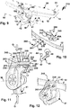
- a trailer coupling 10 comprises a cross member 11 of a carrier arrangement 12.
- the cross member 11 is, for example, at its longitudinal end regions 13 with in Figure 9 side supports 14 shown schematically, which are fastened to a body 91 of a motor vehicle 90, for example screwed and / or welded and / or glued.
- the cross member 12 extends in the transverse direction of the motor vehicle 90, for example behind a bumper 92, so that it is not visible when in use. In principle, it would be possible to connect the cross member 12 directly to the body 91, for example in that the longitudinal ends 13 are screwed, welded or otherwise connected directly to the body 90.
- the cross member 12 has a rectangular cross section with, when the carrier arrangement 11 is mounted on the motor vehicle 90, upper and lower side walls 15, 16 which are connected to one another by a front and rear side wall 17, 18. Curvature sections 19 are provided between the side walls 15-18, so that the profile of the cross member 12 does not have any sharp edges (which, however, would also be possible), but rather rounded edges.
- the cross member 12 is designed as a profile part 20.
- the side walls 15-18 delimit a cavity 21.
- a holder 40 on which a coupling arm 42 is held as a coupling element 41, is arranged on a central section 22 of the cross member 12.
- a coupling piece 43 for coupling a load carrier or as in FIG Figure 9 shown, a trailer 95.
- the trailer 95 has, for example, on its drawbar a so-called ball coupling 96 which can be detachably connected to the coupling piece 43, in this case a coupling ball 44 in a manner known per se.
- a load carrier 195 could be fastened to the coupling piece 43, for example by means of a clamping coupling 196.
- the coupling element 41 is arranged on a holding section 45 of the holder 40.
- a fixed arrangement would be possible here, but also, for example, a plug connection with a plug projection and plug receptacle.
- a plug-in projection 149 is provided for insertion into a plug-in receptacle 148 on the holding section 45.
- the associated locking means are not shown in the drawing.
- the coupling arm 141 could also be in one piece with the holding section 45 or be connected to it, for example, by a screw connection or a welded connection.
- the coupling element 41 is mounted pivotably about a pivot axis W between a use position G and a non-use position N, in which it is not suitable for attaching a trailer or a load carrier.
- the coupling arm 42 is hidden behind the bumper 92, while in the use position G it protrudes in front of the bumper with the coupling piece 43.
- the holding section 45 comprises a holding arm 46 which protrudes from a base body 47 of the holder 40.
- a bearing receptacle 48 is provided on the holding arm 46, in which, for example, a bearing pin is held in a fixed or rotatable manner and which engages in a pivot section 49 of the coupling element 41.
- a locking arrangement for locking the coupling element 41 with respect to the holder 40 in the use position G and the non-use position N only form-fit receptacles 49A are visible in the drawing.
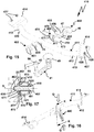
- the holder 40 is supported on the cross member 12 on an abutment surface 50.
- a side support surface 51 projects in front of the abutment surface 50.
- the cross member 12 is supported with its lower side wall 16 on the side support surface 51 and with its front side wall 17 on the abutment surface 50.
- the abutment surface 50 and the side support surface 51 are therefore arranged at the same angle to one another as the outer sides of the side walls 17, 18.
- the cross member 12 is positively supported in a receptacle 53 of the holder 40 and not only in one direction, but in directions that are angled to one another.
- the side support surface 51 is provided, for example, on a support leg 54 which protrudes at an angle in front of a screw leg 55.
- the support leg 54 and the fastening leg 55 are formed on the base body 47.
- the fastening leg 55 is used to fasten the cross member 12 using a tie rod arrangement 60.
- the tie rod arrangement 60 comprises tie rods 61, which passage openings 24, 23 on the side walls 18, 17 penetrate and are screwed into screw receptacles 56 on the holder 40.
- the screw receptacles 56 are located on the abutment surface 50.
- the tie rods 61 can therefore be screwed along their tension rod clamping axis S in the direction of the abutment surface 50, whereby they brace the cross member 12 with the receptacle 50, namely in the direction of the abutment surface 50.
- the tie rods 61 are received in support sleeves 70 which form support elements 80 and have through openings 71 for the tie rods 61.
- the tie rods 61 have heads 62 which are received in head receptacles 72.
- the head receptacles 72 are provided on head sections 73 of the support sleeves 70 which protrude laterally in front of the through openings 54 on the side wall 18.
- the head sections 73 are therefore supported with support surfaces 74 on the side wall 18, so that ultimately the heads 62 of the tie rods 61 and the head sections 73 of the support sleeves 70 tension the side wall 18 in the direction of the abutment surface 50 and therefore in the direction of the holder 40.
- the cross member 12 is loaded in the direction of the holder 40 by means of the support sleeves 70 and the tie rod 61.
- the support sleeve 70 offers resistance.
- the support sleeve 70 ensures that the tie rod 61 also loads the side wall 17 in the direction of the abutment surface 50.
- a step is provided between a sleeve section 76 of the support sleeve 70 and a support projection 77 of the support sleeve 70.
- the support projection 77 projects in front of a step 75.
- the side support surface 74 or step 75 is supported on the side wall 17.
- the support projection 77 penetrates the receptacle 23 and a through opening 86 of a support element 85 and then penetrates into a receptacle 57 of the holder 50.
- the support projection 77 is supported on its outer circumference both on the circumferential side in the passage opening 23 and in the receptacle 57.
- the inner cross-section of the passage opening 86 of the support element 85 is also adapted to the outer contour of the support projection 77, so that it is received in a form-fitting manner in all three components 57, 86, 23 mentioned.
- the support projection 77 can effectively absorb forces or transverse forces acting transversely to the clamping axis S without these loading the tie rod 61 at its screw section 63.
- the screw section 63 is provided on a free end region of the tie rod 61, which in the present case is designed as a screw bolt.
- the screw portion 63 and the head 62 are provided on the longitudinal end portions of a bolt portion 64.
- the bolt section 64 is received in the sleeve section 76.
- the screw section 63 projects in front of the sleeve section 76 and is screwed into a screw section 58 of the screw receptacle 56 of the holder 40.
- the holder 40 is connected by means of a tie rod arrangement 160 to a cross member 112 of a carrier arrangement 111, which is fundamentally very similar to the cross member 12, but undergoes a deformation at the central section 22 due to the tie rod arrangement 160, which will be described later.
- the tie rod arrangement 160 comprises tie rods 161, for example screw bolts 166, which are designed as step bolts.
- the tie rods 161 have heads 162 which are supported on the outside of the side wall 18.
- Bolt sections 164 of the tie rods 161 penetrate into the cavity 21 between the side walls 17, 18.
- a support surface 74 on the head section or head 162 is supported on the outside of the side wall 18 and loads it in the direction of the side wall 17 facing the holder 40.
- a side wall section 115 and a side wall section 116 of the upper and lower side walls 15, 16 are formed, which form a deformation 126 inwardly in the direction of the cavity 21.
- the middle section 22 is additionally stiffened.
- a support projection 177 protrudes in front of the bolt section 164 and is received in the receptacle 57 of the holder 40, which has already been explained.
- the support projection 177 penetrates the passage opening 23 on the side wall 17, the passage opening 86 of the support element 85 and finally penetrates into the receptacle 77.
- the support projection 77 can thus also absorb transverse forces Q occurring transversely to the clamping axis S.
- a step 175 is provided between the support projection 177 and the bolt section 164.
- the side wall 17 is tensioned or loaded in the direction of the abutment surface 50.
- the support element 85 lying between the abutment surface 50 and the side wall 17 transmits the tensioning force of the tie rod 161, which acts on the cross member 112, to the abutment surface 50.
- the cross member 112 rests on the side support surface 51.
- the holder 40 is thus supported transversely to the clamping axis S on the one hand by the support projection 77 and on the other hand by the surfaces of the side wall 16 and the side support surface 51 that act on one another.
- the tie rod 161 Compared to the trailer coupling 10, assembly is easier to the extent that the tie rod 161 simultaneously forms a support element, i.e. no additional support sleeve 70 has to be fitted. Accordingly, the tie rod 161 preferably has a larger, resilient cross section to the clamping axis S. In particular, the support projection 177 has a larger cross section than the screw section 163.
- a holder 240 of a trailer coupling 210 partially has the same or similar components as the holder 40.
- the receptacle 253 basically corresponds to the receptacle 53, but is not L-shaped, but U-shaped.
- a further support leg 259 namely protrudes from the bottom surface or base surface of the receptacle 253 and lies opposite the support leg 254.
- the two support legs 254, 259 have opposite side support surfaces 251, 252, between which the cross member 12 is received in a form-fitting manner.
- the tie rods 261 include, for example, screw bolts, the screw sections 263 of which are screwed into nuts 266.
- the tie rods 261 are supported with their heads 262 on the side wall 18 and penetrate the passage openings 24, 23 of the cross member 12 and a passage opening 266 of a bottom wall of the receptacle 253, the nut 266 being supported on a rear side of this bottom wall.
- the bottom wall of the receptacle 253 and the cross member 12 are clamped between the nut 266 and the head 262.
- a support sleeve 230 is provided which is supported on the end face on the one hand on the side wall 17, but on the other end face provides an abutment surface 233 for the head 262.
- the abutment surface 233 does not protrude in front of an outside of the side wall 18, that is to say it is flush with the side wall 18 or below it.
- the head 262 cannot deform the side wall 18, or only to a small extent, in the direction of the side wall 18 of the cross member 12, so that its support structure or cross-sectional contour is retained and undamaged.
- a holder 340 which is constructed similarly to the holder 40 and pivotally supports a coupling arm 42 or a coupling element 41, is connected to the already known cross member 12, namely on the basis of the tie rod arrangement 260 already explained unlike the holder 240, only one support leg 354, which is the support leg 54 corresponds, while a support leg corresponding to the support leg 259 is not present.
- the already explained support element 85 ie a plate with passage openings 86, is provided, which is supported on the abutment surface 350 (corresponding to the abutment surfaces 50, 250) and sandwiched between the side wall 17 and this abutment surface 350 is.
- a further support element or a washer 367 is provided below the head 262 or between the head 262 and the side wall 18 in order to counter the force acting from the head 262 on the side wall 18 in the direction of the clamping axis S over a large area laterally next to the Initiate passage opening 24 on the cross member 12.
- non-horizontal bracing of the cross member and holder is also possible, e.g. vertical bracing, which is provided on the basis of a tie rod 361.
- the tie rod 361 clamps the cross member 12, for example, against the side support surface 351, which in this case represents, so to speak, an abutment surface with respect to the tensioning axis of the tie rod 361.
- the function of the abutment surface 50 is also different in this case, namely that of a side support surface.
- several tie rods acting in different directions or tensioning directions are possible when attaching a holder to the cross member of a trailer coupling.
- the tie rods 261 and additionally the tie rods 361 or several of the tie rods 361 for fastening the holder 340 to the cross member 12 could be provided.
- a holder 440 is connected to a cross member 412 of a carrier arrangement 411 by means of a tie rod arrangement 460.
- the cross member 412 has a round, in particular circular, cross section, that is, unlike the cross member 12, is not polygonal.
- a side wall of the cross member 12 has, for example, upper, lower and front and rear side wall sections (in the position of use or in the state of the carrier arrangement 412 mounted on the motor vehicle 90), with only one side wall below 417, which is attached to the holder 440 and is directly supported there, is explained in detail.
- the holder 440 has the known base body 47, of which a holding arm 76 is provided for holding and, in particular, pivotable mounting of the coupling element 41 already explained.
- a receptacle 453 for the cross member 412 is provided on the base body 47.
- the receptacle 453 has an abutment surface 450 and a side support surface 451 which protrudes in front of the abutment surface 450 in the direction of the clamping axes S of the tie rods 461 of the tie rod arrangement 460.
- screw receptacles 456 are provided for the tie rods 461, which are screwed into the screw receptacles 456 with screw sections 463.
- the screw bolts or tie rods 461 penetrate through openings 24, 23 of the cross member 12 and are screwed into the screw receptacles 456, as a result of which they clamp the holder 440 along clamping axes S with the cross member 412.
- tie rods 461 penetrate support sleeves 430 which are arranged in the interior space or cavity 421 of the cross member 412.
- the support sleeves 430 serve in particular to prevent the head 462 from deforming a side wall portion 418 of the cross member 412 or profile part 420 opposite the side wall portion 417 or the holder 440 in the direction of the holder 440 or only to a predetermined extent.
- tie rods 461 are supported transversely to the clamping axis S, namely by the side support surface 451, at least indirectly by the side support surface 461.
- a support element 480 in the form of a support plate 470 is arranged in the receptacle 453 and thus between the holder 440 and the cross member 412.
- the support plate 470 has an inner contour 472, which is the outer contour of the cross member 12 is adapted.
- An outer contour 473 of the support element 480 is adapted to an inner contour of the receptacle 453, that is to say to a contour that is defined by the abutment surface 450 and the side support surface 451.
- the support element 480 is thus received in the receptacle 453 in a form-fitting manner.
- the inner contour 472 also enables a form-fitting support of the cross member 412 on the support element 480, namely along the clamping axis S, but also transversely thereto.
- the side support surface 451 is continued, so to speak, by the support element 480 in the direction of the cross member 412, so that a lower side wall section 416 of the cross member 412 is supported transversely to the clamping axis S on the support element 480 and ultimately on the side support surface 451.
- a support section 452 of the support element 480 opposite the side support surface 451 ensures that an upper side wall section 415 of the cross member 12 is also supported on the support element 480 transversely to the clamping axis S.
- the support element 480 also fulfills a guiding and securing function for the screw bolt or tie rod 461.
- the passage opening 471 is provided on a support projection 477 which penetrates into the receptacle 423 of the cross member 412 and thus supports the tie rod 61 transversely to the clamping axis S. Transverse forces acting transversely to the clamping axis S on the combination of holder 440 and cross member 412 are therefore effectively absorbed by the support projection 477.
- a support sleeve 430 On one end face, i.e. facing away from the holder 440 or facing away from the abutment surface 450, of the support projection 477 is supported by a support sleeve 430, which is also penetrated by the screw bolt or tie rod 461.
- the head 462 thus loads the support sleeve 430 along the clamping axis S against the support surface 475, which contributes to the bracing of the support element 480 with the receptacle 453 or the holder 440.
- Fastening means for fastening the carrier arrangement 411 to the motor vehicle 90 are provided on the longitudinal end regions 413 of the cross member 412, which in the Relationship with the trailer coupling 410 is not shown.
- side supports 414 or fastening legs 414 are provided, which have plate-like support elements 426.
- Screw openings 428 are provided on the carrier elements 426, through which screws 427 or the like other screw means for screwing the carrier arrangement 411 to the motor vehicle 90 are provided. With the screws 428, the carrier arrangement 411 can be screwed, for example, to a rear body panel or to longitudinal members of the body 91.
- the support sleeves 430 are expediently flush with the side wall section 418, so that the head 462 can deform the side wall section 418 to a small extent in the direction of the side wall section 417.
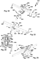
- a holder 540 is attached to the already explained cross member 412 or the carrier arrangement 411.
- the holder 540 has the holding arm 46 and other components in order to hold the coupling element 41, in particular to mount it in a pivotable manner, and in this respect is similar to the holders 40, 440, etc. already described.
- tie rod arrangement 460 which has tie rods 461 which are pushed through the passage openings 24, 23 of the cross member 412 and screwed into screw receptacles 556 of the holder 540.
- the holder 540 has a receptacle 553 for the cross member 412.
- the receptacle 553 has an abutment surface 550 against which the cross member 12 is tensioned along tensioning axes S of the tie rods 461.
- a side support surface 551 is provided on a support leg 554, which protrudes in front of the abutment surface 450, transversely to the clamping axis S or at an angle to the abutment surface 450.
- the abutment surface 550 and the side support surface 551 form the receptacle 553, so that the cross member 412 and the holder 540 are tensioned longitudinally along the clamping axis S by the abutment surface 550 and transversely thereto by the side support surface 451.
- the side support surface 551 preferably extends on both sides of the clamping axis S, that is to say in Figure 21 for example also above the clamping axis S.
- the inner contour of the trough-like receptacle 453 is adapted to the outer contour of the profile part 420 or of the cross member 412, that is to say essentially round.
- a support sleeve 430 is provided in the interior or cavity 421 of the cross member 412, which is supported on the one hand on the head 462 of the respective tie rod 461 and on the other hand on a support projection 577.
- the support projection 577 projects in front of the floor or the abutment surface 550 of the receptacle 553 and penetrates into the passage openings 23 of the profile part 420 or cross member 412.
- the support projection 577 forms, so to speak, a support dome which supports the cross member 412 on the holder 540 transversely to the clamping axis S.
- the side support surfaces 451 and the outer circumference of the support projection 577 thus ensure transverse support of the profile or cross member 12 transversely to the clamping axis S on the holder 540.
- the holder 640 is supported transversely to the clamping axes S of a tie rod arrangement 660, with which the holder 640 is fastened to the cross member 612 of the carrier arrangement 611.
- the cross member 612 has a rectangular cross section, similar to the cross member 12, that is, upper and lower side walls 615, 616 and front and rear side walls 617, 618.
- the cross member 12 comprises a profile part 620 or is formed thereby.
- screw openings or passage openings 628 are provided for screwing to the body 91 of the motor vehicle 90.
- the holder 640 serves to hold a coupling element 641.
- the coupling element 641 is, for example, firmly attached to the holder 640, a pivoting concept according to the previous exemplary embodiments also being possible.
- the coupling element 641 has a coupling arm 642, on the free end region of which a coupling piece 43, in particular a coupling ball, is arranged.
- An arm section 649 of the coupling arm 642 has bores 643 through which fastening bolts (not shown in the drawing), for example Screws that can be pushed through.
- the arm section 649 is received, for example, in a receptacle 648 of the holder 640, which is delimited by side legs 645.
- the receptacle 648 is, for example, U-shaped and provided on a holding arm 646 of the holder 640.
- Passage openings or bores 644 are provided on the side legs 640, which are aligned with the passage openings or bores 643, so that corresponding fastening bolts, screws or the like for fastening the coupling element 641 to the holder 640 can be pushed through the passage openings 644, 643.
- the holder 640 has screw receptacles 656 on a fastening leg 655 from which the holding arm 646 protrudes, into which screw bolts or tie rods 661 can be screwed.
- the screw receptacles 656 are provided on an abutment surface 650.
- the tie rods 661 are pushed through through openings 624, 623 of the cross member 612 and pass through the through openings 656.
- Nuts 666 which are supported on the rear side of the wall 659, are screwed onto the screw sections 663.
- the cross member 612 and the bottom wall or wall 659 are braced to one another by means of the tie rods 661 and are located between the head 662 and the nut 666.
- Support sleeves 630 are provided so that with this bracing the side wall 618 is not or not excessively tensioned in the direction of the side wall 617 and, if necessary, deformed and / or a tensioning force can be exerted by the head 662 along the tensioning axis S on the side wall 617 in the direction of the abutment surface 650 .
- the end of the support sleeves 630 are supported on the one hand on the inside of the side wall 617 facing the cavity 621 and on the other hand provide an end support surface for the head 662 on which it is supported.
- the head 662 presses the support sleeve 630 in the direction of the side wall 617 or biases it in the direction of the clamping axis S against the side wall 17 so that it is clamped against the abutment surface 650 by the support sleeve 630.
- a receptacle 653 is formed in the area of the abutment surface 650.
- support projections 654 protrude, the mutually facing sides of which provide side support surfaces 651 and 652.
- the side support surfaces 651, 652 are at right angles or at least angled to the abutment surface 650.
- a variant of the invention can provide that the upper and lower side walls 615, 616 rest on the side support surfaces 651, 652.
- receptacles 678 are provided on an edge region 619, which is designed as a curved section, between the side walls 15, 17 and 17, 18. The projections or support projections 654 engage with the receptacles 678.
- the heads 662 can be supported by support elements 85 or washers for better force transmission or for the transmission of forces to the side wall 618.
- the support members 85 are sandwiched between the heads 62 and the side wall 618.
Landscapes
- Engineering & Computer Science (AREA)
- Transportation (AREA)
- Mechanical Engineering (AREA)
- Body Structure For Vehicles (AREA)
- Refuge Islands, Traffic Blockers, Or Guard Fence (AREA)
Claims (15)
- Attelage de remorque pour un véhicule à moteur avec un ensemble de support (11), qui présente une traverse (12) prévue pour être disposée sur un hayon d'un véhicule à moteur et un dispositif de maintien (40) maintenu sur la traverse (12) pour maintenir un élément d'attelage (41), en particulier un bras d'attelage (42), de l'attelage de remorque (10), dans lequel l'élément d'attelage (41) est prévu pour fixer une remorque (95) ou un support de charges (195), dans lequel le dispositif de maintien (40) est relié à la traverse (12) à l'aide d'un tirant (61) d'un ensemble de tirants (60), en particulier d'une vis, dans lequel le tirant (61) traverse la traverse (12) le long de son axe de serrage de tirant (S) et serre une face de butée (50), traversée par l'axe de serrage de tirant (S) ou un axe parallèle à l'axe de serrage de tirant (S), du dispositif de maintien (40) contre la traverse (12), et dans lequel le dispositif de maintien (40) présente au moins une face d'appui latérale (51), qui fait saillie devant la face de butée (50) à côté du tirant (61) et repose sur la traverse (12) de sorte que le dispositif de maintien (40) est soutenu sur la traverse (12) latéralement à côté du tirant (61) par rapport à une force agissant de manière transversale par rapport à l'axe de serrage de tirant (S) du tirant (61), caractérisé en ce que l'au moins une face d'appui latérale (51) et la face de butée (50) forment une section transversale en forme de L du dispositif de maintien (40) ou sont disposées en forme de L et/ou le dispositif de maintien (40) est soutenu exclusivement à l'aide de l'au moins une face d'appui latérale (51) et de la face de butée (50) sur la traverse (12) et/ou aucune autre face d'appui latérale du dispositif de maintien ne fait face à l'au moins une face d'appui latérale (51).
- Attelage de remorque selon la revendication 1, caractérisé en ce que l'au moins une face d'appui latérale (51) est à angle droit par rapport à la face de butée (50) ou est une face d'appui latérale (51) qui n'est pas à angle droit par rapport à la face de butée (50), et/ou que l'au moins une face d'appui latérale (51) comprend une face d'appui latérale (51) à angle droit par rapport à la face de butée (50) et/ou une face d'appui latérale (51) qui n'est pas à angle droit par rapport à la face de butée (50), et/ou que l'au moins une face d'appui latérale (51) est une face d'appui latérale (51) arrondie ou en comprend une de ce type.
- Attelage de remorque selon la revendication 1 ou 2, caractérisé en ce que l'au moins une face d'appui latérale (51) et la face de butée (50) s'imbriquent l'une dans l'autre en continu et/ou sans une arête s'étendant entre la face d'appui latérale et la face de butée.
- Attelage de remorque selon l'une quelconque des revendications précédentes, caractérisé en ce que l'au moins une face d'appui latérale (51) et la face de butée (50) réalisent un contour d'incurvation en particulier de forme circulaire, et/ou que l'au moins une face d'appui latérale (51) et la face de butée (50) sont formées par des sections d'une face d'appui globale présentant une section transversale en forme d'arc.
- Attelage de remorque selon l'une quelconque des revendications précédentes, caractérisé en ce qu'un contour de logement, en particulier arrondi, adapté à une zone d'arête de la traverse (12) est disposé entre la face de butée (50) et l'au moins une face d'appui latérale (51), dans lequel il est prévu de manière avantageuse que la traverse (12) repose à plat et/ou par complémentarité de forme sur le contour de logement.
- Attelage de remorque selon l'une quelconque des revendications précédentes, caractérisé en ce que l'au moins une face d'appui latérale (51) prend appui sur une surface, inférieure dans la position d'utilisation et/ou tournée vers une surface de chaussée de circulation, de la traverse (12), et/ou que l'au moins une face d'appui latérale (52) prend appui sur une surface, supérieure dans la position d'utilisation et/ou opposée à une surface de chaussée de circulation, de la traverse (12).
- Attelage de remorque selon l'une quelconque des revendications précédentes, caractérisé en ce que l'au moins une face d'appui latérale est ou comprend une face d'appui latérale qui est disposée sur une partie faisant saillie d'appui (77), qui vient en prise avec un logement (53) sur la traverse (12).
- Attelage de remorque selon la revendication 7, caractérisé en ce que la partie faisant saillie d'appui (77) est disposée à côté de la face de butée (50) ou sur la face de butée (50) et/ou la partie faisant saillie d'appui (77) présente un logement de vissage pour visser le tirant (61) ou un orifice de passage (23) pour le tirant (61).
- Attelage de remorque selon l'une quelconque des revendications précédentes, caractérisé en ce qu'est disposé entre le dispositif de maintien (40) et la traverse (12) un élément d'appui (80, 85), lequel présente au moins un orifice de passage (23) pour l'ensemble de tirants (60).
- Attelage de remorque selon la revendication 9, caractérisé en ce que l'élément d'appui (80, 85) présente des orifices de passage (23) pour au moins deux tirants (61) et/ou présente au moins une partie faisant saillie d'appui (77), laquelle pénètre dans un logement ou un orifice de passage (23) de la traverse (12), et/ou que l'élément d'appui (80, 85) prend appui sur la face de butée (50) et l'au moins une face d'appui latérale du dispositif de maintien (40), et/ou que l'élément d'appui (80) présente un contour extérieur adapté à un contour intérieur, défini en particulier par la face de butée (50) et l'au moins une face d'appui latérale (51) du dispositif de maintien (40), du dispositif de maintien (40), dans lequel le contour extérieur prend appui sur le contour intérieur.
- Attelage de remorque selon l'une quelconque des revendications précédentes, caractérisé en ce que l'au moins une face d'appui latérale (51) est prévue sur une branche d'appui faisant saillie devant un corps de base du dispositif de maintien (40), et/ou le dispositif de maintien (40) présente un renfoncement, dans lequel est prévue de manière opportune sur le fond de celui-ci la face de butée (50).
- Attelage de remorque selon l'une quelconque des revendications précédentes, caractérisé en ce que l'au moins une face d'appui latérale (51) est prévue pour être soutenue sur un côté extérieur de la traverse (12) ou pour être soutenue sur un contour intérieur, en particulier un orifice de passage (23) ou logement, de la traverse (12), et/ou que l'ensemble de tirants (60) présente un premier tirant (61) et un deuxième tirant (61), lesquels sont disposés côte à côte le long d'un axe longitudinal de la traverse (12).
- Attelage de remorque selon l'une quelconque des revendications précédentes, caractérisé en ce que la force, par rapport à laquelle le dispositif de maintien (40) est soutenu sur la traverse (12) à l'aide de l'au moins une face d'appui latérale (51), s'étend à angle droit ou à peu près à angle droit par rapport à l'axe de serrage de tirant (S) du tirant (61) et/ou est ou comprend une force totalement ou sensiblement verticale dans la position d'utilisation.
- Attelage de remorque selon l'une quelconque des revendications précédentes, caractérisé en ce que le dispositif de maintien (40).qu'un logement d'enfichage (148) pour enficher l'élément d'attelage (41) et/ou un palier pour monter de manière à pouvoir pivoter et/ou coulisser l'élément d'attelage (41) entre une position d'utilisation (G) adaptée pour fixer le support de charges (195) ou la remorque (95) et une position de non-utilisation (N) en particulier dissimulée derrière un pare-chocs du véhicule à moteur et/ou l'élément d'attelage (41) sont disposés, en particulier sont vissés, soudés de manière solidaire sur le dispositif de maintien (40) ou d'un seul tenant avec le dispositif de maintien (40).
- Attelage de remorque selon l'une quelconque des revendications précédentes, caractérisé en ce que le tirant traverse la traverse (12) le long de son axe de serrage de tirant (S) et serre la face de butée (50), traversée par l'axe de serrage de tirant (S) ou un axe parallèle à l'axe de serrage de tirant (S), du dispositif de maintien (40) contre une paroi latérale (17) de la traverse (12), qui présente un orifice de passage (23) pour le tirant (61), que l'ensemble de tirants (60) présente un élément d'appui (80) avec une face d'appui latérale (75), configurée en particulier en tant que palier, et une partie faisant saillie d'appui (77) faisant saillie devant la face d'appui latérale (75) en direction de l'axe de serrage de tirant (S), qui pénètre l'orifice de passage (23) de la paroi latérale (17), dans lequel la face d'appui latérale (75) de l'élément d'appui (80) prend appui avec au moins une composante de force en direction de l'axe de serrage (S) sur la paroi latérale (17) de la traverse (12) à côté de l'orifice de passage (23) et la partie faisant saillie d'appui (77) avec au moins une composante de force de manière transversale par rapport à l'axe de serrage (S) dans l'orifice de passage (23).
Applications Claiming Priority (3)
| Application Number | Priority Date | Filing Date | Title |
|---|---|---|---|
| DE102016118677 | 2016-09-30 | ||
| DE102016124562.3A DE102016124562A1 (de) | 2016-09-30 | 2016-12-15 | Anhängekupplung mit einem Zuganker |
| PCT/EP2017/074456 WO2018060227A1 (fr) | 2016-09-30 | 2017-09-27 | Dispositif d'attelage comprenant un tirant |
Publications (2)
| Publication Number | Publication Date |
|---|---|
| EP3519213A1 EP3519213A1 (fr) | 2019-08-07 |
| EP3519213B1 true EP3519213B1 (fr) | 2021-08-25 |
Family
ID=61623632
Family Applications (1)
| Application Number | Title | Priority Date | Filing Date |
|---|---|---|---|
| EP17772713.8A Active EP3519213B1 (fr) | 2016-09-30 | 2017-09-27 | Dispositif d'attelage comprenant un tirant |
Country Status (6)
| Country | Link |
|---|---|
| US (1) | US11220144B2 (fr) |
| EP (1) | EP3519213B1 (fr) |
| CN (1) | CN109890633B (fr) |
| AU (1) | AU2017333381A1 (fr) |
| DE (2) | DE102016124562A1 (fr) |
| WO (1) | WO2018060227A1 (fr) |
Families Citing this family (4)
| Publication number | Priority date | Publication date | Assignee | Title |
|---|---|---|---|---|
| DE102016124562A1 (de) * | 2016-09-30 | 2018-04-05 | Westfalia-Automotive Gmbh | Anhängekupplung mit einem Zuganker |
| DE102016124563A1 (de) * | 2016-09-30 | 2018-04-05 | Westfalia-Automotive Gmbh | Anhängekupplung mit einem Stützelement |
| DE102016119393A1 (de) * | 2016-10-07 | 2018-04-12 | Westfalia-Automotive Gmbh | Anhängekupplung mit einer Anschlussvorrichtung |
| DE102023130113A1 (de) * | 2023-10-31 | 2025-04-30 | ACPS Automotive GmbH | Anhängekupplung |
Family Cites Families (28)
| Publication number | Priority date | Publication date | Assignee | Title |
|---|---|---|---|---|
| US3436100A (en) * | 1967-05-23 | 1969-04-01 | Arcoa Inc | Articulated bumper hitch |
| DE7325210U (de) | 1973-07-09 | 1973-11-08 | Zimmermann K | Vorrichtung zum Abschleppen von Kraft fahrzeugen |
| US4607858A (en) * | 1985-03-26 | 1986-08-26 | Woody's Welding Inc. | Removable hitch |
| AU737395B2 (en) * | 1999-08-26 | 2001-08-16 | Honda Giken Kogyo Kabushiki Kaisha | A joint structure for extruded members |
| US7021646B1 (en) * | 2004-10-27 | 2006-04-04 | Cheng John C | Adjustable receiver hitch |
| US7100936B1 (en) * | 2004-12-13 | 2006-09-05 | Cheng John C | Universal motor vehicle trailer hitch |
| WO2006065117A1 (fr) * | 2004-12-14 | 2006-06-22 | Thule Towing Systems B.V. | Transporteur de charge pour automobiles |
| DE102006045465B4 (de) * | 2006-06-09 | 2017-03-02 | Westfalia-Automotive Gmbh | Anhängerkupplung für Kraftfahrzeuge |
| FR2909948B1 (fr) * | 2006-12-14 | 2009-12-18 | Peugeot Citroen Automobiles Sa | Dispositif d'absorption d'energie pour vehicule automobile |
| DE102008047547B4 (de) * | 2008-09-16 | 2014-04-03 | Westfalia-Automotive Gmbh | Anhängekupplung für Kraftfahrzeuge |
| DE102009035334A1 (de) * | 2009-07-21 | 2011-01-27 | Scambia Industrial Developments Aktiengesellschaft | Anhängekupplung für Kraftfahrzeuge |
| US8590950B2 (en) * | 2011-05-17 | 2013-11-26 | Chrysler Group Llc | Vehicle bumper assembly with a removably coupled tie-down receiver |
| FR2983125B1 (fr) * | 2011-11-25 | 2014-05-02 | Ur Ben | Ensemble d'attelage pour vehicule automobile de traction |
| DE102012022614B3 (de) * | 2012-11-19 | 2014-05-15 | Westfalia-Automotive Gmbh | Anhängesystem für ein Kraftfahrzeug |
| DE102014109134A1 (de) * | 2014-06-30 | 2015-12-31 | Scambia Holdings Cyprus Limited | Anhängekupplung und Lastenträgereinrichtung für eine Anhängekupplung |
| DE102013008323A1 (de) | 2013-05-08 | 2014-11-13 | Westfalia-Automotive Gmbh | Trägeranordnung für eine Anhängekupplung oder einen Lastenträger mit Steckzapfen |
| FR3006243B1 (fr) * | 2013-05-28 | 2016-08-26 | Ur'ben | Ensemble d'attelage double pour vehicule |
| DE102013018771A1 (de) | 2013-11-08 | 2015-05-13 | Westfalia-Automotive Gmbh | Anhängekupplung mit einer Trägeranordnung |
| US9731569B2 (en) * | 2015-01-23 | 2017-08-15 | Ford Global Technologies, Llc | Trailer hitch |
| BR202015009289U2 (pt) * | 2015-04-24 | 2018-01-02 | Keko Acessórios S/A | Disposição construtiva em dispositivo de acoplamento mecânico aplicado em veículos para tração de reboques |
| DE202015104491U1 (de) * | 2015-08-25 | 2016-11-28 | Alois Kober Gmbh | Zugeinrichtung |
| EP3150410B1 (fr) * | 2015-09-30 | 2019-05-08 | WESTFALIA - Automotive GmbH | Attelage doté d'un système support |
| DE102016124562A1 (de) * | 2016-09-30 | 2018-04-05 | Westfalia-Automotive Gmbh | Anhängekupplung mit einem Zuganker |
| DE102017102504A1 (de) * | 2017-02-08 | 2018-08-09 | Bosal Acps Holding 2 B.V. | Anhängekupplung |
| EP3727901B1 (fr) * | 2017-12-20 | 2025-09-24 | Horizon Global (South Africa) (Pty) Ltd | Barre de remorquage pourvue d'un système de boule d'attelage |
| US11179983B2 (en) * | 2018-07-12 | 2021-11-23 | Morgan Olson Corporation | Trailer hitch mounting assembly |
| US11679636B2 (en) * | 2018-12-06 | 2023-06-20 | Midway Products Group, Inc. | Hitch assembly |
| KR102109429B1 (ko) * | 2018-12-28 | 2020-05-12 | 주식회사 성우하이텍 | 트레일러 히치 연결 구조체 |
-
2016
- 2016-12-15 DE DE102016124562.3A patent/DE102016124562A1/de not_active Withdrawn
-
2017
- 2017-09-27 EP EP17772713.8A patent/EP3519213B1/fr active Active
- 2017-09-27 US US16/333,618 patent/US11220144B2/en active Active
- 2017-09-27 AU AU2017333381A patent/AU2017333381A1/en not_active Abandoned
- 2017-09-27 CN CN201780060822.0A patent/CN109890633B/zh active Active
- 2017-09-27 WO PCT/EP2017/074456 patent/WO2018060227A1/fr not_active Ceased
- 2017-09-27 DE DE112017004956.3T patent/DE112017004956A5/de active Pending
Non-Patent Citations (1)
| Title |
|---|
| None * |
Also Published As
| Publication number | Publication date |
|---|---|
| DE112017004956A5 (de) | 2019-06-19 |
| WO2018060227A1 (fr) | 2018-04-05 |
| DE102016124562A1 (de) | 2018-04-05 |
| CN109890633A (zh) | 2019-06-14 |
| US11220144B2 (en) | 2022-01-11 |
| EP3519213A1 (fr) | 2019-08-07 |
| AU2017333381A1 (en) | 2019-04-18 |
| CN109890633B (zh) | 2022-10-21 |
| US20190225039A1 (en) | 2019-07-25 |
Similar Documents
| Publication | Publication Date | Title |
|---|---|---|
| EP3519214B1 (fr) | Dispositif d'attelage comprenant un élément de support | |
| EP2322332B1 (fr) | Bétonnière avec un châssis | |
| EP3519213B1 (fr) | Dispositif d'attelage comprenant un tirant | |
| EP1442942A1 (fr) | Raccord à brides entre un longeron de véhicule et un élément de support fixable à ce dernier | |
| DE19858978A1 (de) | Schwenkbare Anhängerkupplung für Kraftfahrzeuge | |
| DE10297829B4 (de) | Verbesserte Befestigung für eine Kraftfahrzeug-Sicherheitsbarriere | |
| DE102011009636A1 (de) | Anordnung zur Befestigung eines Kraftstoffbehälters an einer Fahrzeugkarosserie | |
| DE102012022876B4 (de) | Hohlprofil mit einem Verstärkungselement | |
| DE10061491C1 (de) | Anhängezugvorrichtung | |
| DE102010010585B4 (de) | Längseinsteller für einen Fahrzeugsitz mit Spindel und Spindelhalter | |
| DE102006055736A1 (de) | Querträger | |
| DE102009058450B3 (de) | Längseinsteller für einen Fahrzeugsitz mit Spindel und Spindelhalter | |
| DE19930945C1 (de) | Befestigungsvorrichtung für den am Sitzteil oder Sitzrahmen festgelegten Beschlagteil eines Beschlages | |
| DE202006012073U1 (de) | Hecklastenträger | |
| DE102008042922B4 (de) | Zaunklammer zur Befestigung eines Zaungitters an einem Pfosten | |
| DE102014009766A1 (de) | Gepäckträger-Anpassungskit zum Anpassen eines Gepäckträgergestells für ein Fahrrad | |
| WO2013153091A1 (fr) | Support de toit pour un porte-bagages de toit pouvant être fixé sur celui-ci | |
| DE102013002820B3 (de) | Fahrzeugsitz mit Verriegelungseinheit | |
| EP2457752B1 (fr) | Dispositif d'embrayage et dispositif d'attelage pour véhicules tracteurs | |
| EP0047961B1 (fr) | Accouplement de rotule d'attelage pour véhicules moteur | |
| EP1488989B2 (fr) | Fermeture à barre rotative pour portes, ridelles ou semblables de superstuctures de véhicules utilitaires | |
| EP4665594A1 (fr) | Attelage de remorque muni d'un ensemble anneau | |
| DE69909666T2 (de) | Vorrichtung zum Verbinden des Ankerkerns eines elastischen Gelenks mit einem Aussenteil | |
| DE102011115627B4 (de) | Spreizvorrichtung | |
| DE102007012118B4 (de) | Einstellpuffer für Kraftfahrzeuge |
Legal Events
| Date | Code | Title | Description |
|---|---|---|---|
| STAA | Information on the status of an ep patent application or granted ep patent |
Free format text: STATUS: UNKNOWN |
|
| STAA | Information on the status of an ep patent application or granted ep patent |
Free format text: STATUS: THE INTERNATIONAL PUBLICATION HAS BEEN MADE |
|
| PUAI | Public reference made under article 153(3) epc to a published international application that has entered the european phase |
Free format text: ORIGINAL CODE: 0009012 |
|
| STAA | Information on the status of an ep patent application or granted ep patent |
Free format text: STATUS: REQUEST FOR EXAMINATION WAS MADE |
|
| 17P | Request for examination filed |
Effective date: 20190402 |
|
| AK | Designated contracting states |
Kind code of ref document: A1 Designated state(s): AL AT BE BG CH CY CZ DE DK EE ES FI FR GB GR HR HU IE IS IT LI LT LU LV MC MK MT NL NO PL PT RO RS SE SI SK SM TR |
|
| AX | Request for extension of the european patent |
Extension state: BA ME |
|
| DAV | Request for validation of the european patent (deleted) | ||
| DAX | Request for extension of the european patent (deleted) | ||
| STAA | Information on the status of an ep patent application or granted ep patent |
Free format text: STATUS: EXAMINATION IS IN PROGRESS |
|
| 17Q | First examination report despatched |
Effective date: 20200507 |
|
| GRAP | Despatch of communication of intention to grant a patent |
Free format text: ORIGINAL CODE: EPIDOSNIGR1 |
|
| STAA | Information on the status of an ep patent application or granted ep patent |
Free format text: STATUS: GRANT OF PATENT IS INTENDED |
|
| INTG | Intention to grant announced |
Effective date: 20210422 |
|
| GRAS | Grant fee paid |
Free format text: ORIGINAL CODE: EPIDOSNIGR3 |
|
| GRAA | (expected) grant |
Free format text: ORIGINAL CODE: 0009210 |
|
| STAA | Information on the status of an ep patent application or granted ep patent |
Free format text: STATUS: THE PATENT HAS BEEN GRANTED |
|
| AK | Designated contracting states |
Kind code of ref document: B1 Designated state(s): AL AT BE BG CH CY CZ DE DK EE ES FI FR GB GR HR HU IE IS IT LI LT LU LV MC MK MT NL NO PL PT RO RS SE SI SK SM TR |
|
| REG | Reference to a national code |
Ref country code: CH Ref legal event code: EP |
|
| REG | Reference to a national code |
Ref country code: IE Ref legal event code: FG4D Free format text: LANGUAGE OF EP DOCUMENT: GERMAN Ref country code: AT Ref legal event code: REF Ref document number: 1423424 Country of ref document: AT Kind code of ref document: T Effective date: 20210915 |
|
| REG | Reference to a national code |
Ref country code: DE Ref legal event code: R096 Ref document number: 502017011317 Country of ref document: DE |
|
| REG | Reference to a national code |
Ref country code: LT Ref legal event code: MG9D |
|
| REG | Reference to a national code |
Ref country code: NL Ref legal event code: MP Effective date: 20210825 |
|
| PG25 | Lapsed in a contracting state [announced via postgrant information from national office to epo] |
Ref country code: HR Free format text: LAPSE BECAUSE OF FAILURE TO SUBMIT A TRANSLATION OF THE DESCRIPTION OR TO PAY THE FEE WITHIN THE PRESCRIBED TIME-LIMIT Effective date: 20210825 Ref country code: SE Free format text: LAPSE BECAUSE OF FAILURE TO SUBMIT A TRANSLATION OF THE DESCRIPTION OR TO PAY THE FEE WITHIN THE PRESCRIBED TIME-LIMIT Effective date: 20210825 Ref country code: RS Free format text: LAPSE BECAUSE OF FAILURE TO SUBMIT A TRANSLATION OF THE DESCRIPTION OR TO PAY THE FEE WITHIN THE PRESCRIBED TIME-LIMIT Effective date: 20210825 Ref country code: LT Free format text: LAPSE BECAUSE OF FAILURE TO SUBMIT A TRANSLATION OF THE DESCRIPTION OR TO PAY THE FEE WITHIN THE PRESCRIBED TIME-LIMIT Effective date: 20210825 Ref country code: BG Free format text: LAPSE BECAUSE OF FAILURE TO SUBMIT A TRANSLATION OF THE DESCRIPTION OR TO PAY THE FEE WITHIN THE PRESCRIBED TIME-LIMIT Effective date: 20211125 Ref country code: NO Free format text: LAPSE BECAUSE OF FAILURE TO SUBMIT A TRANSLATION OF THE DESCRIPTION OR TO PAY THE FEE WITHIN THE PRESCRIBED TIME-LIMIT Effective date: 20211125 Ref country code: PT Free format text: LAPSE BECAUSE OF FAILURE TO SUBMIT A TRANSLATION OF THE DESCRIPTION OR TO PAY THE FEE WITHIN THE PRESCRIBED TIME-LIMIT Effective date: 20211227 Ref country code: ES Free format text: LAPSE BECAUSE OF FAILURE TO SUBMIT A TRANSLATION OF THE DESCRIPTION OR TO PAY THE FEE WITHIN THE PRESCRIBED TIME-LIMIT Effective date: 20210825 Ref country code: FI Free format text: LAPSE BECAUSE OF FAILURE TO SUBMIT A TRANSLATION OF THE DESCRIPTION OR TO PAY THE FEE WITHIN THE PRESCRIBED TIME-LIMIT Effective date: 20210825 |
|
| PG25 | Lapsed in a contracting state [announced via postgrant information from national office to epo] |
Ref country code: PL Free format text: LAPSE BECAUSE OF FAILURE TO SUBMIT A TRANSLATION OF THE DESCRIPTION OR TO PAY THE FEE WITHIN THE PRESCRIBED TIME-LIMIT Effective date: 20210825 Ref country code: LV Free format text: LAPSE BECAUSE OF FAILURE TO SUBMIT A TRANSLATION OF THE DESCRIPTION OR TO PAY THE FEE WITHIN THE PRESCRIBED TIME-LIMIT Effective date: 20210825 Ref country code: GR Free format text: LAPSE BECAUSE OF FAILURE TO SUBMIT A TRANSLATION OF THE DESCRIPTION OR TO PAY THE FEE WITHIN THE PRESCRIBED TIME-LIMIT Effective date: 20211126 |
|
| PG25 | Lapsed in a contracting state [announced via postgrant information from national office to epo] |
Ref country code: NL Free format text: LAPSE BECAUSE OF FAILURE TO SUBMIT A TRANSLATION OF THE DESCRIPTION OR TO PAY THE FEE WITHIN THE PRESCRIBED TIME-LIMIT Effective date: 20210825 |
|
| PG25 | Lapsed in a contracting state [announced via postgrant information from national office to epo] |
Ref country code: DK Free format text: LAPSE BECAUSE OF FAILURE TO SUBMIT A TRANSLATION OF THE DESCRIPTION OR TO PAY THE FEE WITHIN THE PRESCRIBED TIME-LIMIT Effective date: 20210825 |
|
| REG | Reference to a national code |
Ref country code: CH Ref legal event code: PL |
|
| REG | Reference to a national code |
Ref country code: BE Ref legal event code: MM Effective date: 20210930 |
|
| REG | Reference to a national code |
Ref country code: DE Ref legal event code: R097 Ref document number: 502017011317 Country of ref document: DE |
|
| PG25 | Lapsed in a contracting state [announced via postgrant information from national office to epo] |
Ref country code: SM Free format text: LAPSE BECAUSE OF FAILURE TO SUBMIT A TRANSLATION OF THE DESCRIPTION OR TO PAY THE FEE WITHIN THE PRESCRIBED TIME-LIMIT Effective date: 20210825 Ref country code: SK Free format text: LAPSE BECAUSE OF FAILURE TO SUBMIT A TRANSLATION OF THE DESCRIPTION OR TO PAY THE FEE WITHIN THE PRESCRIBED TIME-LIMIT Effective date: 20210825 Ref country code: RO Free format text: LAPSE BECAUSE OF FAILURE TO SUBMIT A TRANSLATION OF THE DESCRIPTION OR TO PAY THE FEE WITHIN THE PRESCRIBED TIME-LIMIT Effective date: 20210825 Ref country code: MC Free format text: LAPSE BECAUSE OF FAILURE TO SUBMIT A TRANSLATION OF THE DESCRIPTION OR TO PAY THE FEE WITHIN THE PRESCRIBED TIME-LIMIT Effective date: 20210825 Ref country code: EE Free format text: LAPSE BECAUSE OF FAILURE TO SUBMIT A TRANSLATION OF THE DESCRIPTION OR TO PAY THE FEE WITHIN THE PRESCRIBED TIME-LIMIT Effective date: 20210825 Ref country code: CZ Free format text: LAPSE BECAUSE OF FAILURE TO SUBMIT A TRANSLATION OF THE DESCRIPTION OR TO PAY THE FEE WITHIN THE PRESCRIBED TIME-LIMIT Effective date: 20210825 Ref country code: AL Free format text: LAPSE BECAUSE OF FAILURE TO SUBMIT A TRANSLATION OF THE DESCRIPTION OR TO PAY THE FEE WITHIN THE PRESCRIBED TIME-LIMIT Effective date: 20210825 |
|
| PLBE | No opposition filed within time limit |
Free format text: ORIGINAL CODE: 0009261 |
|
| STAA | Information on the status of an ep patent application or granted ep patent |
Free format text: STATUS: NO OPPOSITION FILED WITHIN TIME LIMIT |
|
| GBPC | Gb: european patent ceased through non-payment of renewal fee |
Effective date: 20211125 |
|
| PG25 | Lapsed in a contracting state [announced via postgrant information from national office to epo] |
Ref country code: LU Free format text: LAPSE BECAUSE OF NON-PAYMENT OF DUE FEES Effective date: 20210927 Ref country code: IT Free format text: LAPSE BECAUSE OF FAILURE TO SUBMIT A TRANSLATION OF THE DESCRIPTION OR TO PAY THE FEE WITHIN THE PRESCRIBED TIME-LIMIT Effective date: 20210825 Ref country code: IE Free format text: LAPSE BECAUSE OF NON-PAYMENT OF DUE FEES Effective date: 20210927 Ref country code: BE Free format text: LAPSE BECAUSE OF NON-PAYMENT OF DUE FEES Effective date: 20210930 |
|
| 26N | No opposition filed |
Effective date: 20220527 |
|
| PG25 | Lapsed in a contracting state [announced via postgrant information from national office to epo] |
Ref country code: SI Free format text: LAPSE BECAUSE OF FAILURE TO SUBMIT A TRANSLATION OF THE DESCRIPTION OR TO PAY THE FEE WITHIN THE PRESCRIBED TIME-LIMIT Effective date: 20210825 Ref country code: LI Free format text: LAPSE BECAUSE OF NON-PAYMENT OF DUE FEES Effective date: 20210930 Ref country code: CH Free format text: LAPSE BECAUSE OF NON-PAYMENT OF DUE FEES Effective date: 20210930 |
|
| PG25 | Lapsed in a contracting state [announced via postgrant information from national office to epo] |
Ref country code: GB Free format text: LAPSE BECAUSE OF NON-PAYMENT OF DUE FEES Effective date: 20211125 |
|
| PG25 | Lapsed in a contracting state [announced via postgrant information from national office to epo] |
Ref country code: CY Free format text: LAPSE BECAUSE OF FAILURE TO SUBMIT A TRANSLATION OF THE DESCRIPTION OR TO PAY THE FEE WITHIN THE PRESCRIBED TIME-LIMIT Effective date: 20210825 |
|
| PG25 | Lapsed in a contracting state [announced via postgrant information from national office to epo] |
Ref country code: HU Free format text: LAPSE BECAUSE OF FAILURE TO SUBMIT A TRANSLATION OF THE DESCRIPTION OR TO PAY THE FEE WITHIN THE PRESCRIBED TIME-LIMIT; INVALID AB INITIO Effective date: 20170927 |
|
| REG | Reference to a national code |
Ref country code: AT Ref legal event code: MM01 Ref document number: 1423424 Country of ref document: AT Kind code of ref document: T Effective date: 20220927 |
|
| PG25 | Lapsed in a contracting state [announced via postgrant information from national office to epo] |
Ref country code: AT Free format text: LAPSE BECAUSE OF NON-PAYMENT OF DUE FEES Effective date: 20220927 |
|
| PG25 | Lapsed in a contracting state [announced via postgrant information from national office to epo] |
Ref country code: MK Free format text: LAPSE BECAUSE OF FAILURE TO SUBMIT A TRANSLATION OF THE DESCRIPTION OR TO PAY THE FEE WITHIN THE PRESCRIBED TIME-LIMIT Effective date: 20210825 |
|
| PG25 | Lapsed in a contracting state [announced via postgrant information from national office to epo] |
Ref country code: TR Free format text: LAPSE BECAUSE OF FAILURE TO SUBMIT A TRANSLATION OF THE DESCRIPTION OR TO PAY THE FEE WITHIN THE PRESCRIBED TIME-LIMIT Effective date: 20210825 |
|
| PG25 | Lapsed in a contracting state [announced via postgrant information from national office to epo] |
Ref country code: MT Free format text: LAPSE BECAUSE OF FAILURE TO SUBMIT A TRANSLATION OF THE DESCRIPTION OR TO PAY THE FEE WITHIN THE PRESCRIBED TIME-LIMIT Effective date: 20210825 |
|
| PGFP | Annual fee paid to national office [announced via postgrant information from national office to epo] |
Ref country code: DE Payment date: 20250929 Year of fee payment: 9 |
|
| PGFP | Annual fee paid to national office [announced via postgrant information from national office to epo] |
Ref country code: FR Payment date: 20250925 Year of fee payment: 9 |