EP3519325B1 - Getränkepatrone für getränkeherstellungsmaschinen - Google Patents
Getränkepatrone für getränkeherstellungsmaschinen Download PDFInfo
- Publication number
- EP3519325B1 EP3519325B1 EP17857185.7A EP17857185A EP3519325B1 EP 3519325 B1 EP3519325 B1 EP 3519325B1 EP 17857185 A EP17857185 A EP 17857185A EP 3519325 B1 EP3519325 B1 EP 3519325B1
- Authority
- EP
- European Patent Office
- Prior art keywords
- beverage
- beverage material
- material container
- cartridge
- mixing funnel
- Prior art date
- Legal status (The legal status is an assumption and is not a legal conclusion. Google has not performed a legal analysis and makes no representation as to the accuracy of the status listed.)
- Active
Links
Images


Classifications
-
- B—PERFORMING OPERATIONS; TRANSPORTING
- B65—CONVEYING; PACKING; STORING; HANDLING THIN OR FILAMENTARY MATERIAL
- B65D—CONTAINERS FOR STORAGE OR TRANSPORT OF ARTICLES OR MATERIALS, e.g. BAGS, BARRELS, BOTTLES, BOXES, CANS, CARTONS, CRATES, DRUMS, JARS, TANKS, HOPPERS, FORWARDING CONTAINERS; ACCESSORIES, CLOSURES, OR FITTINGS THEREFOR; PACKAGING ELEMENTS; PACKAGES
- B65D85/00—Containers, packaging elements or packages, specially adapted for particular articles or materials
- B65D85/70—Containers, packaging elements or packages, specially adapted for particular articles or materials for materials not otherwise provided for
- B65D85/804—Disposable containers or packages with contents which are mixed, infused or dissolved in situ, i.e. without having been previously removed from the package
- B65D85/8043—Packages adapted to allow liquid to pass through the contents
-
- A—HUMAN NECESSITIES
- A47—FURNITURE; DOMESTIC ARTICLES OR APPLIANCES; COFFEE MILLS; SPICE MILLS; SUCTION CLEANERS IN GENERAL
- A47J—KITCHEN EQUIPMENT; COFFEE MILLS; SPICE MILLS; APPARATUS FOR MAKING BEVERAGES
- A47J31/00—Apparatus for making beverages
- A47J31/40—Beverage-making apparatus with dispensing means for adding a measured quantity of ingredients, e.g. coffee, water, sugar, cocoa, milk, tea
- A47J31/407—Beverage-making apparatus with dispensing means for adding a measured quantity of ingredients, e.g. coffee, water, sugar, cocoa, milk, tea with ingredient-containing cartridges; Cartridge-perforating means
-
- B—PERFORMING OPERATIONS; TRANSPORTING
- B65—CONVEYING; PACKING; STORING; HANDLING THIN OR FILAMENTARY MATERIAL
- B65D—CONTAINERS FOR STORAGE OR TRANSPORT OF ARTICLES OR MATERIALS, e.g. BAGS, BARRELS, BOTTLES, BOXES, CANS, CARTONS, CRATES, DRUMS, JARS, TANKS, HOPPERS, FORWARDING CONTAINERS; ACCESSORIES, CLOSURES, OR FITTINGS THEREFOR; PACKAGING ELEMENTS; PACKAGES
- B65D85/00—Containers, packaging elements or packages, specially adapted for particular articles or materials
- B65D85/70—Containers, packaging elements or packages, specially adapted for particular articles or materials for materials not otherwise provided for
- B65D85/804—Disposable containers or packages with contents which are mixed, infused or dissolved in situ, i.e. without having been previously removed from the package
Definitions
- This invention relates to a beverage cartridge to be used with a beverage forming system, such an infant formula or other beverage machine.
- Cartridges for use with beverage forming machines are well known, and may include a variety of different beverage materials, such as ground coffee beans, tea leaves, powdered drink mix, powdered infant formula, etc.
- WO2018007383A1 is prior art under Article 54(3) EPC and discloses a package having a sealable concentrate container for holding beverage concentrate and an extraction and mixing device.
- a beverage cartridge in one aspect, includes a cup defining an opening to an internal space for containing a beverage material used to make a beverage, such as a powdered infant formula that is mixed with water.
- the cup may include an outwardly extending rim arranged around the opening that has a top side and a bottom side.
- a cover may close the opening and engage with the rim to seal the internal space from an external environment, e.g., to protect a beverage material in the cup from moisture, oxygen, etc.
- the cover may include a body having a periphery and a plurality of flexible tabs arranged around the periphery of the cover.
- the cover may be positioned below the cup and the flexible tabs may be arranged to engage the top side of the rim and bias the cover against the rim, e.g., so that rim and cover form a seal.
- the flexible tabs may be arranged as finger-shaped elements with each flexible tab forming a cantilever that is attached at a proximal end to the body and extending away from the proximal end to a free distal end.
- the cantilever may have a rod-like or beam-like shape such that the cantilever is elongated, e.g., the cantilever is longer than it is wide.
- the cover includes a peripheral lip that extends upwardly from the body around the periphery, and the flexible tabs extending downwardly and inwardly from the peripheral lip.
- the flexible tabs are arranged to flex outwardly to receive the rim into a space between the flexible tabs and the body.
- the cartridge may also include a sealing boss on the rim or the body of the cover to seal the internal space closed.
- the sealing boss may include a resilient, gasket-type element the deforms with engagement between the rim and cover and provides the seal.
- the body includes a movable portion located between two stationary portions.
- the movable portion may be joined to the stationary portions by respective break lines that are arranged to open with movement of the movable portion relative to the stationary portions. For example, the movable portion may be pressed to move towards the internal space of the cup so as to move relative to the stationary portions. This movement may cause the break lines to open, creating one or more openings into the internal space. Beverage material in the internal space may exit the cartridge via the one or more openings, e.g., by falling due to gravity from the openings.
- the break lines may include perforations, scoring or thinned sections of the body so that movement of the movable portion causes the perforated, scored or thinned sections to break or separate to form the one or more openings.
- the movable portion may extend across the body from one side of the periphery to another side of the periphery.
- the body may be circular, and the movable portion may extend across the circular shape from one side to the other, e.g., the movable portion may include a diameter line that extends through a center of the circular shape.
- the break lines may also extend across the body from one side of the periphery to another side of the periphery, e.g., the break lines may form a type of chord line that extends across a circular shape of the body.
- the break lines may terminate short of the periphery such that the movable portion remains attached to the body after the break lines are open. For example, if the body has a circular shape, the break lines may extend close to, but up to, the outer circular periphery of the body.
- a beverage cartridge in another aspect, includes a cup defining an opening to an internal space for containing a beverage material used to make a beverage.
- the cup may include a rim arranged around the opening, a sidewall that extends downwardly from the rim, and a bottom at a lower end of the sidewall.
- a cover may be arranged to close the opening and engage with the rim to seal the internal space from an external environment, such as moisture, oxygen, etc.
- the cover may be positioned below the cup and have a body with a periphery engaged with the rim, a movable portion extending across the body from one side of the periphery to another side of the periphery, and at least two stationary portions on opposite sides of the movable portion.
- the movable portion may be joined to the stationary portions by respective break lines arranged to open with movement of the movable portion relative to the stationary portions.
- the movable portion may extend across a center of the body and may be pushed to move toward the internal space of the cup, causing the break lines to open and allow beverage material to exit the cartridge.
- a central area of the movable portion may be wider than ends of the movable portion that are nearer the periphery.
- the cover includes a peripheral lip arranged to engage with the rim to hold the cover on the cup and that extends upwardly from the body around the periphery.
- the break lines which may include perforations, scoring or thinned sections of the body, may extend across the body from one side of the periphery to another side of the periphery, but may terminate short of the periphery such that the movable portion remains attached to the body after the break lines are open.
- a mixing funnel for use with a beverage cartridge includes a funnel body defining a bowl portion having a sidewall and a bottom.
- the bottom includes an outlet opening, and the sidewall has a rim at an upper end of the sidewall and a gap at a portion of the sidewall.
- An inlet channel extends radially outwardly from the gap and is arranged to receive liquid into the inlet channel in an axial direction and to direct the liquid into the bowl portion such that the liquid enters the bowl portion and follows an arcuate pathway around the bowl portion. That is, the rim of the bowl portion may define an upper opening of the funnel body, and the inlet channel may provide a radial extension from the upper opening.
- Water of other liquid may enter the inlet channel in a downward direction (an axial direction), and then flow generally horizontally (a radial direction) into the funnel body so that the liquid swirls around the bowl portion. Such swirling flow may aid in mixing of the liquid with a beverage material in the bowl portion.
- the mixing funnel may be arranged to engage with a beverage material container at the rim of the sidewall and to receive a beverage material from the beverage material container into the bowl portion, e.g., so that beverage material dispensed from the container into the bowl portion can mix with water or other liquid provided to the inlet channel.
- the beverage material container may be positioned over the bowl portion so that when the container is opened, beverage material drops from the container into the bowl portion.
- the funnel body includes a spike that extends upwardly from the bottom of the bowl portion and is arranged to contact and open the beverage material container.
- the beverage material container may include a piercable or otherwise openable section located over the spike, and the spike and container may be movable towards each other so that the spike causes the beverage material container to open, releasing beverage material.
- the mixing funnel is arranged to engage the beverage material container and to move toward the beverage material container while remaining engaged with the beverage material container such that the spike opens the beverage material container. That is, the beverage material container and the mixing funnel may be forced towards each other so that the spike contacts the beverage material container and causes the container to open.
- the mixing funnel may have different features to aid in mixing, exit of beverage from the funnel or other features.
- the outlet opening may be offset from a center of the bowl portion. That is, the bowl portion may be generally symmetrical with a circular cross section that allows fluid to flow in a circular path in the bowl portion. However, the outlet opening may be offset from center of the bowl portion, which has been found to aid in beverage exiting the bowl portion, e.g., by reducing splashing at the outlet.
- the inlet channel has a U shape when viewed from a top side, e.g., to provide a smooth flow path and transition for liquid that enters the inlet channel to the bowl portion.
- the inlet channel has a bottom that is positioned above the bottom of the bowl portion, e.g., so that liquid in the inlet channel can flow downwardly into the bowl portion to drain the inlet channel.
- the rim of the bowl portion includes a stepped portion arranged to receive the beverage material container.
- the stepped portion may form an internal ledge or shelf below the top edge of the rim. A portion of the beverage material container may be received into the stepped portion so that the container can move toward the mixing funnel while remaining positioned at least partially in the stepped portion.
- the stepped portion is arranged to engage the beverage material container at a first position and at a second position, where the beverage material container is positioned further within the bowl portion in the second position than in the first position.
- the funnel body may include a spike that extends upwardly from the bottom of the bowl portion, and if so, may be arranged to contact and open the beverage material container when the beverage material container is moved from the first position to the second position.
- the stepped portion may be configured to function as a stop to limit movement of the beverage material container into the bowl portion.
- a beverage cartridge in another aspect, includes a beverage material container having a beverage material in an internal space and being arranged to be opened to release the beverage material, and a mixing funnel attached to the beverage material container and arranged to receive beverage material released from the beverage material container and to receive liquid that is mixed with the beverage material in the mixing funnel.
- the beverage material container and the mixing funnel may be movable towards each other while remaining attached together so as to open the beverage material container and release the beverage material into the mixing funnel.
- the beverage material container may be partially received into the mixing funnel when moving toward the mixing funnel to open the beverage material container.
- the beverage material container includes a cover with one or more break lines
- the mixing funnel includes a pusher element arranged to contact the cover and cause the one or more break lines to open with movement of the beverage material container toward the mixing funnel.
- the mixing funnel may include a bowl portion with a bottom and a sidewall and the pusher element may extend upwardly from the bottom to contact the cover of the beverage material container.
- the cover includes a movable portion located between two stationary portions with the movable portion joined to the stationary portions by respective break lines arranged to open with movement of the movable portion relative to the stationary portions.
- the pusher element may be arranged to contact and move the movable portion with movement of the beverage material container towards the mixing funnel.
- the beverage material container is movable relative to the mixing funnel from a first position in which the internal space is closed to a second position in which the internal space is opened to release the beverage material.
- the beverage cartridge may include a detent that operates to maintain the beverage material container at the first position in the absence of an external force, and permits the beverage material container to move to the second position only if an external force applied to the beverage material container and mixing funnel exceeds a threshold.
- the threshold is 10 pounds, e.g., a suitable level to help prevent unwanted opening of the container during shipping and other handling of the cartridge prior to use.
- a beverage dispensing system in another aspect, includes a beverage cartridge having a beverage material container with a beverage material in an internal space, and a mixing funnel attached to the beverage material container and arranged to receive beverage material released from the beverage material container and to receive liquid that is mixed with the beverage material in the mixing funnel.
- a beverage making machine may have a cartridge holder arranged to receive the beverage cartridge with the cartridge holder including a vibration mechanism arranged to vibrate the beverage cartridge and cause beverage material to be dispensed from the beverage material container into the mixing funnel once the beverage material container is opened.
- the vibration mechanism includes a yoke that extends at least partially around the beverage material container and transmits vibratory motion to the beverage material container.
- the yoke may include an annular ring that extends around the beverage material container, although other configurations are possible.
- the vibration mechanism may include a motor that moves the yoke in a horizontal plane, e.g., the vibration mechanism may include a motor with an eccentric drive linked between the motor and the yoke.
- the cartridge holder may be arranged to move the beverage material container and the mixing funnel toward each other to open the beverage material container and dispense beverage material into the mixing funnel.
- the cartridge holder may be arranged to hold the beverage cartridge in an orientation with the beverage material container positioned over the mixing funnel such that beverage material dispensed from the beverage material container falls into the mixing funnel.
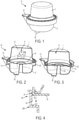
- FIGS. 1-3 show a perspective view and side cross-sectional views, respectively, of an illustrative cartridge 10 that incorporates one or more aspects of the invention.
- the cartridge 10 may be used in a beverage machine to form any suitable beverage such as tea, coffee, and other beverages, including beverages formed from a liquid or powdered concentrate, etc.
- the cartridge 10 may contain any suitable beverage material, e.g., ground coffee, tea leaves, dry herbal tea, powdered beverage concentrate, dried fruit extract or powder, powdered or liquid concentrated bouillon or other soup, powdered or liquid medicinal materials (such as powdered vitamins, drugs or other pharmaceuticals, nutriceuticals, etc.), and/or other beverage-making material (such as powdered milk or other creamers, sweeteners, thickeners, flavorings, and so on).
- the cartridge 10 contains a beverage material that is configured for use with a machine that forms coffee and/or tea beverages, however, aspects of the invention are not limited in this respect. An arrangement like that in FIGs.
- FIGs. 1-3 has been found particularly effective for use with a dry, powdered infant formula composition.
- arrangements like that in FIGs. 1-3 have been found to be capable of consistently solubilizing spray dried powders that are highly soluble (like dairy powders and infant formula) without the need for secondary processing.
- Powders intended to be solubilized are typically processed, sometime at great expense, to optimize their rate solubility to achieve a more complete wetting of the powder.
- highly soluble materials like infant formula or dairy powders, these can be processed through granulation techniques like agglomeration or roller compaction to slow the rate at which they take on water or other liquid. This is because particles which are highly soluble can wet too quickly at the bulk powder/water interface and form a viscous front that prevents further wetting of powder below.
- Embodiments described below allow a highly soluble, dry material such as spray-dried dairy powder or infant formula to be metered or otherwise dispensed into a liquid in a way that prevents the formation of a viscous front and thus creating a more uniform solution in the final beverage. This result can be achieved without the need or expense of secondary processing, such as agglomeration, to manipulate the particle size of the powder.
- the cartridge 10 includes a beverage material container 1 and a mixing funnel 2.
- beverage material 12 shown schematically in FIG. 2 but otherwise omitted for clarity
- liquid such as water
- the beverage material container 1 may be opened to dispense beverage material 12 into the mixing funnel 2, and liquid provided to the mixing funnel 2 at an inlet channel 21 may mix with the beverage material 12 to form a beverage that exits via an outlet opening 22.
- the material 12 may fall from the container 1 into the mixing funnel 2 to be mixed with liquid in the funnel 2. Liquid to be mixed with the material 12 may be sprayed or otherwise dispensed into the open area at the top of the inlet channel 21.
- One feature of this embodiment is that no part of a beverage machine that uses the cartridge 10 need be exposed to, or contact, beverage material 12 in the container 1. Instead, the container 1 may be opened by a part of the mixing funnel 2 and beverage material 12 may be dispensed only into the mixing funnel 2, which may be later discarded or cleaned and reused. Also, the beverage machine using the cartridge 10 may dispense liquid into the inlet channel 21 without contacting the mixing funnel 2 or any other part of the cartridge 10, and the beverage produced in the mixing funnel 2 may be dispensed directly into a user's cup or other container. These features can help avoid contamination of the beverage machine because contact with the beverage material 12 can be avoided, thereby eliminating the need to clean or disinfect the machine after beverage formation.
- the beverage material container 1 and the mixing funnel 2 may be arranged to be moved towards each other while remaining attached together so as to open the beverage material container 1 and release the beverage material 12 into the mixing funnel 2. That is, prior to use, the beverage material container 1 may be sealed closed with beverage material 12 contained inside the container 1 and isolated from external environmental conditions, such as moisture, oxygen, etc.
- the beverage material container 1 and mixing funnel 2 may be attached together prior to use, e.g., at the time or manufacture, so that a user need not associate a container 1 and funnel 2 together prior to use. Instead, the user may provide the cartridge 10 assembly as one piece to a beverage machine, which may receive the cartridge 10 and open the beverage material container 1 by moving the beverage material container 1 and mixing funnel 2 towards each other.
- Such an arrangement may provide for simplified operation, e.g., because cartridge holders in beverage machines are typically made to clamp a beverage cartridge and such clamping action may cause the beverage material container 1 to be opened.
- the beverage material container 1 includes a cover 13 with one or more break lines 14, and the mixing funnel 2 includes a pusher element 24 arranged to contact the cover 13 and cause the one or more break lines 14 to open with movement of the beverage material container 1 toward the mixing funnel 2.
- the beverage material container 1 may be movable relative to the mixing funnel 2 from a first position in which the internal space 11 is closed to a second position in which the internal space 11 is opened to release the beverage material 12.
- the beverage material 12 may be released by causing the one or more break lines 14 to open, allowing the beverage material 12 to fall into the mixing funnel 2.
- the beverage material container 1 may be received at least partially into the mixing funnel 2 when moving toward the mixing funnel 2.
- the mixing funnel 2 may include a stepped portion 23 configured to receive the lower portion of the beverage material container 1 (i.e., the cover 13) and may function as a stop to limit movement of the beverage material container 1 into the mixing funnel 2.
- the stepped portion 23 may be arranged to allow the beverage material container 1 to be moved into the mixing funnel 2 until the cover 13 of the beverage material container 1 contacts a horizontal step or ledge 231 of the mixing funnel 2 which stops further motion of the beverage material container 1.
- the beverage cartridge 10 may include a detent that operates to hold the beverage material container 1 and the mixing funnel 2 together and to maintain the beverage material container 1 at the first position in the absence of an external force.
- the detent may permit the beverage material container 1 to move to the second position if an external force applied to the beverage material container 1 and mixing funnel 2 exceeds a threshold.
- this embodiment includes a detent 30 that includes an upper circumferential notch 31 and a lower circumferential protrusion 32 at the stepped portion 23 and a protrusion 33 on the cover 13. With the beverage material container 1 in the first position shown in FIG.
- the protrusion 33 on the cover 13 engages with the notch 31 to maintain the beverage material container 1 in the first position until a force exceeding a threshold (such as 10 pounds of force) is exerted on the beverage cartridge 1 to move the beverage material container 1 and the mixing funnel 2 towards each other.
- a threshold such as 10 pounds of force
- the protrusion 33 disengages from the notch 31 and the beverage material container 1 moves toward the mixing funnel 2 until the protrusion 33 clears, or moves below, the protrusion 32 on the stepped portion 23.
- the cover 13 then contacts the step or ledge of the mixing funnel 2 and stops movement toward the mixing funnel 2.
- the protrusions 32, 33 may be arranged to prevent movement of the beverage material container 1 and the mixing funnel 2 away from each other in the absence of a suitable threshold force exerted to separate the beverage material container 1 and the mixing funnel 2.
- a suitable threshold force may be greater than a threshold force needed to move the beverage material container 1 from the first position, e.g., may be 15 pounds or greater.
- Such an arrangement may provide a ready indication that the cartridge 10 has been used, e.g., because a user may view the cartridge 10 and see that the container 1 is received into the mixing funnel 2 and therefore has been used.
- a beverage machine that uses the cartridge 10 may detect that no force is needed to move the beverage material container 1 and the mixing funnel 2 toward each other, and associate this lack of force with an indication that the cartridge 10 has already been used.
- the machine may refuse operation in such a case, and/or provide a display to a user with a suitable message.
- the internal space 11 may be opened so that beverage material 12 may exit the container 1.
- the pusher element 24 contacts a movable portion of the cover 13 so that the movable portion of the cover 13 moves relative to one or more stationary portions of the cover 13. Movable and stationary portions of the cover 13 may be arranged in a variety of different ways.
- the pusher element 24 may include a spike that penetrates a part of the cover, moving portions of the cover 13 so as to form an opening in the cover 13 while other portions of the cover 13 are not contacted or moved by the pusher element 24.
- the pusher element 24 may break one or more portions of the cover 13 free so as to create one or more openings through which beverage material may exit the internal space 11.
- the cover 13 includes a movable portion that spans across the cover 13 and is movable relative to stationary portions on opposite sides of the movable portion. Break lines 14 between the movable portion and the stationary portions release when the pusher element 24 moves the movable portion upwardly as shown in FIG. 3 , creating openings through which beverage material 12 may exit.
- FIG. 5 shows a bottom view of the cover 13 in this embodiment and illustrates break lines 14 that are provided between the movable portion 131 and stationary portions 132 on opposite sides of the movable portion 131.
- the movable portion 131 is located between two stationary portions 132, and the movable portion 131 is joined to the stationary portions 132 by respective break lines 14 arranged to open with movement of the movable portion 131 relative to the stationary portions 132. That is, the pusher element 24 may contact and move the movable portion 131 upwardly relative to the stationary portions 132 and into the internal space 11 of the container 1 with movement of the beverage material container 1 towards the mixing funnel 2, as shown in FIGs. 3 and 6 .
- the break lines 14 may include perforations, scoring or thinned sections of the body of the cover 13.
- the cover 13 may include a relatively thin membrane, such as a polymer sheet, that is adhered to or molded with the body of the cover 13.
- Other areas of the cover 13 away from the break lines 14 may be thicker or otherwise more resistant to tearing or breaking.
- the membrane may be arranged to tear or rip when the movable portion 131 is moved relative to the stationary portions 132, e.g., with contact by the pusher element 24.
- the movable portion 131 is wider in a center area than in outer, peripheral ends of the movable portion 131.
- the movable portion 131 extends across the body of the cover 13 from one side of a periphery 133 of the cover 13 to another side of the periphery 133, and may extend across a center of the body.
- the break lines 14 may extend across the body from one side of the periphery 133 to another side of the periphery 133.
- the break lines 14 may form chord lines, whether straight, curved or irregular in shape, that extend across the body of the cover 13.
- the break lines 14 may terminate short of the periphery 133 such that the movable portion 131 remains attached to the body after the break lines 14 are open.
- the movable portion may be arranged in other ways, and there may be two or more movable portions, and/or one or more stationary portions.
- the movable portions may have a triangular, semi-circular or other desired shape, and may be arranged to detach completely or partially from the stationary portion via break lines 14.
- the movable portions may pivot about a hinge portion arranged adjacent the periphery 133 so that the movable portions can hinge upwardly and into the internal space 11 when opening in a way similar to the FIG. 3 and 6 embodiment.
- a pusher element 24 may be arranged to individually contact the movable portions to cause the break lines 14 to separate, move the movable portions and create desired openings in the cover 13.
- the beverage material container may include a cover that engages with a cup of the container without the use of adhesive or welding.
- the cover may include locking elements that engage with the cup and hold the cover in place, and the cover may sealingly engage with the cup so as to seal the internal space of the container closed to protect the beverage material from external conditions, such as moisture, oxygen, etc.
- the beverage material container 1 may include a cup defining an opening to the internal space 11 for containing beverage material used to make a beverage.
- the cup 15 may include an outwardly extending rim 151 arranged around the opening that has a top side and a bottom side.
- the bottom side may include a sealing boss 152 extending downwardly from the bottom side.
- the cover 13 may be arranged to close the opening and engage with the sealing boss 152 to seal the internal space from an external environment.
- the cover 13 may include a body having a periphery 133 and a plurality of flexible tabs 134 arranged around the periphery 133 of the cover 13.
- the flexible tabs 134 may be arranged to engage the top side of the rim 151 and bias the cover 13 against the sealing boss 152 to seal the internal space 12. That is, as shown in FIGs.
- the cover 13 may be forced onto the rim 151 so that the flexible tabs 134 pivot outwardly to allow the rim 151 to clear the lower ends of the flexible tabs 134 and be received into a space between the flexible tabs 134 and the body. With the rim 151 positioned below the tabs 134, the tabs 134 may flex inwardly to capture the rim 151. It should be noted that although the sealing boss 152 is on the rim 151 in this embodiment, the sealing boss 152 could be positioned on the cover 13 instead. Also, in this embodiment, the cover includes a peripheral lip 135 that extends upwardly from the body around the periphery 133, and the flexible tabs 134 extend downwardly and inwardly from the peripheral lip 135.
- the flexible tabs 134 could be supported in different ways.
- the tabs 134 could extend from the body of the cover 13 and be positioned inside of the internal space 11 to engage the sidewall of the cup 15.
- the cup sidewall could include a ledge or step located below the rim 151 that engages with the ends of the flexible tabs 134 in a way similar to how the tabs 134 capture the rim 151.
- the mixing funnel for use with a beverage cartridge is arranged with a funnel body defining a bowl portion 25 having a sidewall and a bottom, e.g., as shown in FIG. 9 .
- the bottom includes an outlet opening 22, and the sidewall has a rim at an upper end of the sidewall and a gap 26 at a portion of the sidewall.
- An inlet channel 21 extends radially from the gap 26 and is arranged to receive liquid into the inlet channel 21 in an axial direction (as shown by the arrow 101 in FIG. 9 ) and to direct the liquid into the bowl portion 25 through the gap 26 such that the liquid enters the bowl portion and follows an arcuate pathway around the bowl portion (as shown by the arrow 102 in FIG. 9 ).
- the funnel body may include a spike or other pusher element 24 that extends upwardly from the bottom of the bowl portion 25 and is arranged to contact and open the beverage material container 1.
- the outlet opening 22 may be offset from a center of the bowl portion, e.g., to a side of the pusher element 24.
- a center of the bowl portion e.g., to a side of the pusher element 24.
- the inlet channel 21 has a U shape when viewed from a top side, and the inlet channel 21 has a bottom that is positioned above the bottom of the bowl portion. This arrangement of the inlet channel bottom may aid in having liquid flow downwardly into the bowl portion 25 to help drain the inlet channel 21 and create a swirling flow pattern in the bowl portion 25.
- the mixing funnel 2 may include a stepped portion 23 near the rim of the bowl portion 25 arranged to receive the beverage material container 1. That is, the stepped portion 23 may be arranged to engage the beverage material container 1 at a first position and at a second position, where the beverage material container 1 is positioned further within the bowl portion 25 in the second position than in the first position. When the beverage material container 1 is in the second position, the pusher element 24 may contact and open the beverage material container 1.
- a beverage cartridge including a beverage material container and a mixing funnel are arranged for use in a beverage dispensing system.
- the beverage cartridge may be received in a cartridge holder of a beverage machine arranged similarly to coffee machines that accept cartridges to form a beverage (whether coffee, tea or other beverage types).
- a beverage machine may have a cartridge holder that accepts the beverage cartridge, opens the beverage cartridge (e.g., to release beverage material), and provides water or other liquid to the cartridge to form a beverage.
- the cartridge holder may have a hand-operated mechanism that can be opened to receive the cartridge and closed to at least partially enclose the cartridge.
- Closing of the cartridge holder may move the beverage material container and mixing funnel towards each other, thereby opening the beverage material container to dispense beverage material into the mixing funnel.
- the cartridge holder may engage the container and the funnel and push the two towards each other to cause a pusher element of the mixing funnel to open the container in a way like that described above. Thereafter, water or other liquid may be dispensed into the mixing funnel for mixing with the beverage material and later dispensing of beverage.
- a beverage making machine having a cartridge holder to receive the beverage cartridge may include a vibration mechanism arranged to vibrate the beverage cartridge and cause beverage material to be dispensed from the beverage cartridge into the mixing funnel.
- FIG. 10 shows a beverage cartridge 10 received by a cartridge holder 5 of a beverage making machine.
- the cartridge holder 5 includes an upper portion 51 that engages with the beverage material container 1 and a lower portion 52 that engages the mixing funnel 2.
- the upper portion 51 includes a yoke that at least partially extends around the container 1.
- the upper and lower portions 51, 52 are moved toward each other, thereby moving the container 1 and funnel 2 towards each other and opening the container 1 to release beverage material 12 into the funnel 1.
- Cartridge holders 5 having upper and lower portions that receive and enclose a cartridge in this manner are widely used in coffee brewers, and any suitable arrangement may be employed.
- the cartridge holder 5 also includes a vibration mechanism 53 arranged to vibrate the container 1 and/or the funnel 2.
- the vibration mechanism 53 may include a motor with an eccentric drive that causes the yoke of the upper portion 51 to vibrate in a horizontal plane at about 135 Hz and with a 2mm amplitude.
- other vibratory frequencies and amplitudes may be used, and the cartridge 10 may be vibrated in directions other than horizontal, such as a vertical directions and/or direction that have horizontal and vertical components.
- Such motion may aid in dispensing beverage material 12 from the container 1, particularly if the beverage material 12 includes a powder, such as an infant formula.
- liquid may be dispensed by the machine into the mixing funnel 2 to mix with beverage material 12 dispensed from the container 1.
- vibration or other movement of the cartridge 1 need not be employed in all embodiments.
- liquid may be delivered into the beverage material container 1 to mix with beverage material 12 in the container 1.
- the container 1 may be pierced by an inlet piercing element (e.g., a needle, knife, blade, etc.) so that water or other liquid may be injected into the cartridge 10.
- Beverage formed in the container 1 may be dispensed through an opening in the cover 13, or another part of the container 1, and the opening may be formed by piercing or other action such as that described above.
- the cartridge 10 may include other elements, such as one or more filters to filter beverage prior to exiting a beverage machine.
- a filter may be provided in the beverage material container 1, in the mixing funnel 2 (e.g., at the outlet 22), or elsewhere.
- "beverage” refers to a liquid substance intended for drinking that is formed when a liquid interacts with a beverage material.
- beverage refers to a liquid that is ready for consumption, e.g., is dispensed into a cup and ready for drinking, as well as a liquid that will undergo other processes or treatments, such as filtering or the addition of flavorings, creamer, sweeteners, another beverage, etc., before being consumed.
- beverage material 12 is located only in a single chamber of the beverage material container 1
- beverage material of one or more different types may be provided in two or more chambers of the container.
- a cartridge may include roast and ground coffee in a first chamber, and a creamer and sweetener in the second chamber, enabling the cartridge to form a cappuccino- or latte-like beverage.
- the first chamber may include coffee grounds and the second chamber may include a hot chocolate material, allowing the cartridge to form a mocha-type beverage.
- Other combinations will occur to those of skill in the art, such as leaf tea in the first chamber and a dried fruit material in the second chamber, a dried fruit material in the first chamber and creamer/sweetener in the second chamber, and so on.
- another filter may be provided, e.g., to separate beverage media in the second chamber from the fluid outlet.
- water or other liquid may be provided into a first chamber of the container 1 to mix with beverage material 12, while beverage material in a second chamber may be dispensed in dry or powder form into the mixing funnel 2 for mixing with beverage that exits the first chamber.
Landscapes
- Engineering & Computer Science (AREA)
- Mechanical Engineering (AREA)
- Food Science & Technology (AREA)
- Apparatus For Making Beverages (AREA)
Claims (14)
- Mischtrichter (2) zur Verwendung mit einer Getränkekartusche (10), umfassend:einen Trichterkörper, der einen Schalenabschnitt (25) definiert, der eine Seitenwand und einen Boden aufweist, wobei der Boden eine Auslassöffnung (22) beinhaltet und die Seitenwand einen Rand (151) an einem oberen Ende der Seitenwand und einen Spalt (26) an einem Abschnitt der Seitenwand aufweist; undeinen Einlasskanal (21), der sich radial von dem Spalt (26) erstreckt und angeordnet ist, um Flüssigkeit in den Einlasskanal (21) in einer axialen Richtung (101) aufzunehmen und um die Flüssigkeit in den Schalenabschnitt (25) zu leiten, sodass die Flüssigkeit in den Schalenabschnitt (25) eintritt und einem bogenförmigen Weg um den Schalenabschnitt (25) folgt.
- Mischtrichter (2) nach Anspruch 1, wobei der Mischtrichter (2) angeordnet ist, um mit einem Getränkematerialbehälter (1) an dem Rand (151) der Seitenwand in Eingriff zu kommen und um ein Getränkematerial (12) aus dem Getränkematerialbehälter (1) in den Schalenabschnitt (25) aufzunehmen.
- Mischtrichter (2) nach Anspruch 2, wobei der Trichterkörper eine Spitze beinhaltet, die sich von dem Boden des Schalenabschnittes (25) nach oben erstreckt und angeordnet ist, um den Getränkematerialbehälter (1) zu kontaktieren und zu öffnen.
- Mischtrichter (2) nach Anspruch 2 oder Anspruch 3, wobei der Rand (151) einen abgestuften Abschnitt (23) beinhaltet, der angeordnet ist, um den Getränkematerialbehälter (1) aufzunehmen, wobei der abgestufte Abschnitt (23) angeordnet ist, um den Getränkematerialbehälter (1) an einer ersten Position und an einer zweiten Position in Eingriff zu nehmen, wobei der Getränkematerialbehälter (1) in der zweiten Position weiter innerhalb des Schalenabschnittes (25) positioniert ist als in der ersten Position.
- Mischtrichter (2) nach Anspruch 4, wobei der Trichterkörper eine Spitze beinhaltet, die sich von dem Boden des Schalenabschnittes (25) nach oben erstreckt und angeordnet ist, um den Getränkematerialbehälter (1) zu kontaktieren und zu öffnen, wenn sich der Getränkematerialbehälter (1) in der zweiten Position befindet.
- Getränkekartusche (10), umfassend:einen Getränkematerialbehälter (1), der ein Getränkematerial (12), z. B. ein Pulver, in einem Innenraum (11) aufweist, wobei der Getränkematerialbehälter (1) angeordnet ist, um geöffnet zu werden, um das Getränkematerial (12) auszugeben; undeinen Mischtrichter (2) nach einem der Ansprüche 1 bis 5, der an dem Getränkematerialbehälter (1) angebracht und angeordnet ist, um Getränkematerial (12) aufzunehmen, das aus dem Getränkematerialbehälter (1) ausgegeben wird, und um Flüssigkeit aufzunehmen, die mit dem Getränkematerial (12) in dem Mischtrichter (2) vermischt wird;wobei der Getränkematerialbehälter (1) und der Mischtrichter (2) angeordnet sind, um aufeinander zu bewegt zu werden, während sie aneinander angebracht bleiben, um den Getränkematerialbehälter (1) zu öffnen und das Getränkematerial (12) in den Mischtrichter (2) auszugeben.
- Getränkekartusche (10) nach Anspruch 6, wobei der Mischtrichter (2) angeordnet ist, um mit dem Getränkematerialbehälter (1) an dem Rand (151) der Seitenwand in Eingriff zu kommen und um ein Getränkematerial (12) aus dem Getränkematerialbehälter (1) in den Schalenabschnitt (25) aufzunehmen.
- Getränkekartusche (10) nach Anspruch 7, wobei der Getränkematerialbehälter (1) teilweise in den Mischtrichter (2) aufgenommen wird, um den Getränkematerialbehälter (1) zu öffnen.
- Getränkekartusche (10) nach Anspruch 7 oder Anspruch 8, wobei der Getränkematerialbehälter (1) eine Abdeckung (13) mit einer oder mehreren Bruchlinien (14) beinhaltet und der Mischtrichter (2) ein Schieberelement (24) beinhaltet, das angeordnet ist, um die Abdeckung (13) zu kontaktieren und zu bewirken, dass sich die eine oder die mehreren Bruchlinien (14) mit Bewegung des Getränkematerialbehälters (1) in Richtung des Mischtrichters (2) öffnen.
- Getränkekartusche (10) nach Anspruch 9, wobei sich das Schieberelement (24) von dem Boden des Trichters (2) nach oben erstreckt, wobei die Abdeckung (13) einen beweglichen Abschnitt beinhaltet, der sich zwischen zwei stationären Abschnitten befindet, wobei der bewegliche Abschnitt mit den stationären Abschnitten durch jeweilige Bruchlinien (14) zusammengefügt ist, die angeordnet sind, um sich mit Bewegung des beweglichen Abschnittes relativ zu den stationären Abschnitten zu öffnen, und wobei das Schieberelement (24) angeordnet ist, um den beweglichen Abschnitt mit Bewegung des Getränkematerialbehälters (1) in Richtung des Mischtrichters (2) zu kontaktieren und zu bewegen.
- Getränkekartusche (10) nach einem der Ansprüche 6 bis 10, wobei der Getränkematerialbehälter (1) relativ zu dem Mischtrichter (2) von einer ersten Position, in welcher der Innenraum (11) geschlossen ist, in eine zweite Position bewegbar ist, in welcher der Innenraum (11) geöffnet ist, um das Getränkematerial (12) auszugeben, und wobei die Getränkekartusche (1) eine Arretierung beinhaltet, die arbeitet, um den Getränkematerialbehälter (1) in der Abwesenheit einer externen Kraft in der ersten Position zu halten, und nur dann zulässt, dass sich der Getränkematerialbehälter (1) in die zweite Position bewegt, wenn eine externe Kraft, die auf den Getränkematerialbehälter (1) und den Mischtrichter (2) ausgeübt wird, einen Schwellenwert überschreitet.
- Getränkeabgabesystem, umfassend:eine Getränkekartusche (10) nach einem der Ansprüche 6 bis 11; undeine Getränkezubereitungsmaschine, die einen Kartuschenhalter (5) aufweist, der angeordnet ist, um die Getränkekartusche (10) aufzunehmen, wobei der Kartuschenhalter (5) einen Vibrationsmechanismus (53) beinhaltet, der angeordnet ist, um die Getränkekartusche (10) zu vibrieren und zu bewirken, dass Getränkematerial (12) aus der Getränkekartusche (10) in den Mischtrichter (2) abgegeben wird.
- System nach Anspruch 12, wobei der Vibrationsmechanismus (53) einen Bügel (51) beinhaltet, der sich zumindest teilweise um den Getränkematerialbehälter (1) erstreckt und Vibrationsbewegung auf den Getränkematerialbehälter (1) überträgt.
- System nach Anspruch 13, wobei der Vibrationsmechanismus (53) einen Motor mit einem Exzenterantrieb beinhaltet, der zwischen dem Motor und dem Bügel (51) verbunden ist.
Applications Claiming Priority (2)
| Application Number | Priority Date | Filing Date | Title |
|---|---|---|---|
| US201662400713P | 2016-09-28 | 2016-09-28 | |
| PCT/US2017/051124 WO2018063791A1 (en) | 2016-09-28 | 2017-09-12 | Beverage cartridge for beverage making machines |
Publications (3)
| Publication Number | Publication Date |
|---|---|
| EP3519325A1 EP3519325A1 (de) | 2019-08-07 |
| EP3519325A4 EP3519325A4 (de) | 2020-09-09 |
| EP3519325B1 true EP3519325B1 (de) | 2022-02-16 |
Family
ID=61760133
Family Applications (1)
| Application Number | Title | Priority Date | Filing Date |
|---|---|---|---|
| EP17857185.7A Active EP3519325B1 (de) | 2016-09-28 | 2017-09-12 | Getränkepatrone für getränkeherstellungsmaschinen |
Country Status (4)
| Country | Link |
|---|---|
| US (1) | US11634271B2 (de) |
| EP (1) | EP3519325B1 (de) |
| CA (1) | CA3037706A1 (de) |
| WO (1) | WO2018063791A1 (de) |
Families Citing this family (11)
| Publication number | Priority date | Publication date | Assignee | Title |
|---|---|---|---|---|
| US11832755B2 (en) * | 2007-07-13 | 2023-12-05 | Adrian Rivera | Brewing material container for a beverage brewer |
| US10722066B2 (en) * | 2010-12-04 | 2020-07-28 | Adrian Rivera | Windowed single serving brewing material holder |
| US10071851B2 (en) | 2010-07-12 | 2018-09-11 | Robert Bao Vu | Apparatus and products for producing beverages, and methods for making and using same |
| KR102318476B1 (ko) * | 2010-07-22 | 2021-11-01 | 카-페 시스템 게엠베하 | 음료수 제조를 위한 1인용 캡슐 |
| US12185866B2 (en) * | 2013-02-01 | 2025-01-07 | Adrian Rivera | Brewing cartridge adapter |
| US11013364B2 (en) * | 2013-02-01 | 2021-05-25 | Adrian Rivera | Brewing cartridge adapter |
| GB2587321B (en) * | 2019-08-15 | 2023-06-07 | Douwe Egberts Bv | Beverage ingredient containers, methods of making and methods of using the same |
| US11805934B1 (en) * | 2020-10-21 | 2023-11-07 | Adrian Rivera | Brewing material lid and container for a beverage brewer |
| US20240308838A1 (en) * | 2021-07-15 | 2024-09-19 | Freezio Ag | Cartridge system comprising a cartridge closed by a valve |
| TW202322735A (zh) * | 2021-09-30 | 2023-06-16 | 瑞士商雀巢製品股份有限公司 | 飲料或食物容器及製備系統 |
| US12005408B1 (en) | 2023-04-14 | 2024-06-11 | Sharkninja Operating Llc | Mixing funnel |
Family Cites Families (18)
| Publication number | Priority date | Publication date | Assignee | Title |
|---|---|---|---|---|
| CH605293A5 (de) | 1976-12-17 | 1978-09-29 | Nestle Sa | |
| US5897899A (en) | 1991-05-08 | 1999-04-27 | Nestec S.A. | Cartridges containing substances for beverage preparation |
| FR2815610B1 (fr) * | 2000-10-23 | 2003-02-14 | Valois Sa | Dispositif de fixation et distributeur utilisant un tel dispositif de fixation |
| US7316178B2 (en) * | 2003-01-24 | 2008-01-08 | Kraft Foods R & D, Inc. | Machine for the preparation of beverages |
| BRPI0419063A (pt) * | 2004-09-17 | 2007-12-11 | Tuttoespresso Spa | cápsula descartável para preparação de uma bebida, e método para abrir uma cápsula para preparação de uma bebida |
| SG175793A1 (en) * | 2009-05-05 | 2011-12-29 | Nestec Sa | Capsule for preparing a nutritional product including a filter |
| JP5702779B2 (ja) * | 2009-07-24 | 2015-04-15 | エシカル コーヒー カンパニー ソシエテ アノニム | カプセルから抽出される飲料を調製するためのデバイス |
| DE102009058646A1 (de) * | 2009-12-16 | 2011-06-22 | Krüger GmbH & Co. KG, 51469 | Portionskapsel und Verwendung einer Portionskapsel |
| US20120006204A1 (en) * | 2010-07-09 | 2012-01-12 | Crane Merchandising Systems, Inc. | Modular vending machine and cartridge system |
| TW201318564A (zh) * | 2011-06-15 | 2013-05-16 | Green Mountain Coffee Roasters Inc | 飲料形成設備及使用振動能的方法 |
| PL2869739T3 (pl) * | 2012-07-06 | 2016-09-30 | Sposób i urządzenie do parzenia napoju | |
| MX2015004269A (es) | 2012-10-12 | 2015-08-07 | Nestec Sa | Tarjeta contenedora de ingredientes de alimentos o bebidas. |
| GB2506940B (en) * | 2012-10-15 | 2015-09-30 | Zendegii Ltd | Beverage dispensing machine |
| ITBS20130081A1 (it) * | 2013-05-30 | 2014-12-01 | Capitani Srl | Capsula per la produzione di una bevanda infusa |
| US9278801B2 (en) | 2013-12-18 | 2016-03-08 | Robert Gruder | Beverage mixing cartridge and method of using same |
| US9867494B2 (en) * | 2014-07-18 | 2018-01-16 | Spencer Frazer | Reciprocating coffee filter |
| US20170208988A1 (en) * | 2014-07-21 | 2017-07-27 | Abbott Laboratories | Hot and cold water delivery to pod containing nutritional composition |
| CH712695A1 (de) | 2016-07-07 | 2018-01-15 | Mühlemann Ip Gmbh | Einportionenpackung zur Herstellung eines Getränks aus einem Getränkekonzentrat. |
-
2017
- 2017-09-12 EP EP17857185.7A patent/EP3519325B1/de active Active
- 2017-09-12 US US16/336,585 patent/US11634271B2/en active Active
- 2017-09-12 WO PCT/US2017/051124 patent/WO2018063791A1/en not_active Ceased
- 2017-09-12 CA CA3037706A patent/CA3037706A1/en active Pending
Also Published As
| Publication number | Publication date |
|---|---|
| CA3037706A1 (en) | 2018-04-05 |
| US20190225414A1 (en) | 2019-07-25 |
| EP3519325A4 (de) | 2020-09-09 |
| WO2018063791A1 (en) | 2018-04-05 |
| US11634271B2 (en) | 2023-04-25 |
| EP3519325A1 (de) | 2019-08-07 |
Similar Documents
| Publication | Publication Date | Title |
|---|---|---|
| EP3519325B1 (de) | Getränkepatrone für getränkeherstellungsmaschinen | |
| EP2155019B1 (de) | Verfahren zur herstellung eines getränks oder flüssigen nahrungsmittels | |
| CN102196752B (zh) | 通过离心作用制备容纳在胶囊中的液体食品的方法及适合于该方法的系统 | |
| US9840365B2 (en) | Capsule and a system for, and a method of, preparing a beverage | |
| EP2210539B1 (de) | Vorrichtung und System zur Herstellung eines Getränks unter Verwendung von Zentrifugalkraft | |
| US20170142995A1 (en) | Capsule and method for preparing a food liquid by centrifugation | |
| US20170362020A1 (en) | Capsule for preparing consummable product | |
| HK1161670A (en) | Method for preparing a food liquid contained in a capsule by centrifugation and system adapted for such method | |
| HK1141696B (en) | Method for preparing a beverage or liquid food | |
| AU2014268242A1 (en) | Capsule for preparing a beverage or liquid food and system using brewing centrifugal force | |
| HK1146205A (en) | Capsule for preparing a beverage or liquid food and system using brewing centrifugal force | |
| HK1126372B (en) | Method for preparing a beverage or liquid food and system using brewing centrifugal force | |
| HK1146206A (en) | Device and system for preparing a beverage using brewing centrifugal force | |
| HK1146699A (en) | Capsule for preparing a beverage or liquid food and system using brewing centrifugal force |
Legal Events
| Date | Code | Title | Description |
|---|---|---|---|
| STAA | Information on the status of an ep patent application or granted ep patent |
Free format text: STATUS: THE INTERNATIONAL PUBLICATION HAS BEEN MADE |
|
| PUAI | Public reference made under article 153(3) epc to a published international application that has entered the european phase |
Free format text: ORIGINAL CODE: 0009012 |
|
| STAA | Information on the status of an ep patent application or granted ep patent |
Free format text: STATUS: REQUEST FOR EXAMINATION WAS MADE |
|
| 17P | Request for examination filed |
Effective date: 20190403 |
|
| AK | Designated contracting states |
Kind code of ref document: A1 Designated state(s): AL AT BE BG CH CY CZ DE DK EE ES FI FR GB GR HR HU IE IS IT LI LT LU LV MC MK MT NL NO PL PT RO RS SE SI SK SM TR |
|
| AX | Request for extension of the european patent |
Extension state: BA ME |
|
| DAV | Request for validation of the european patent (deleted) | ||
| DAX | Request for extension of the european patent (deleted) | ||
| RIC1 | Information provided on ipc code assigned before grant |
Ipc: A47J 31/40 20060101ALI20200501BHEP Ipc: B65D 85/804 20060101AFI20200501BHEP |
|
| A4 | Supplementary search report drawn up and despatched |
Effective date: 20200810 |
|
| RIC1 | Information provided on ipc code assigned before grant |
Ipc: B65D 85/804 20060101AFI20200804BHEP Ipc: A47J 31/40 20060101ALI20200804BHEP |
|
| STAA | Information on the status of an ep patent application or granted ep patent |
Free format text: STATUS: EXAMINATION IS IN PROGRESS |
|
| 17Q | First examination report despatched |
Effective date: 20210512 |
|
| GRAP | Despatch of communication of intention to grant a patent |
Free format text: ORIGINAL CODE: EPIDOSNIGR1 |
|
| STAA | Information on the status of an ep patent application or granted ep patent |
Free format text: STATUS: GRANT OF PATENT IS INTENDED |
|
| INTG | Intention to grant announced |
Effective date: 20211006 |
|
| GRAS | Grant fee paid |
Free format text: ORIGINAL CODE: EPIDOSNIGR3 |
|
| GRAA | (expected) grant |
Free format text: ORIGINAL CODE: 0009210 |
|
| STAA | Information on the status of an ep patent application or granted ep patent |
Free format text: STATUS: THE PATENT HAS BEEN GRANTED |
|
| AK | Designated contracting states |
Kind code of ref document: B1 Designated state(s): AL AT BE BG CH CY CZ DE DK EE ES FI FR GB GR HR HU IE IS IT LI LT LU LV MC MK MT NL NO PL PT RO RS SE SI SK SM TR |
|
| REG | Reference to a national code |
Ref country code: GB Ref legal event code: FG4D |
|
| REG | Reference to a national code |
Ref country code: CH Ref legal event code: EP |
|
| REG | Reference to a national code |
Ref country code: DE Ref legal event code: R096 Ref document number: 602017053540 Country of ref document: DE |
|
| REG | Reference to a national code |
Ref country code: AT Ref legal event code: REF Ref document number: 1468754 Country of ref document: AT Kind code of ref document: T Effective date: 20220315 |
|
| REG | Reference to a national code |
Ref country code: IE Ref legal event code: FG4D |
|
| REG | Reference to a national code |
Ref country code: LT Ref legal event code: MG9D |
|
| REG | Reference to a national code |
Ref country code: NL Ref legal event code: MP Effective date: 20220216 |
|
| REG | Reference to a national code |
Ref country code: AT Ref legal event code: MK05 Ref document number: 1468754 Country of ref document: AT Kind code of ref document: T Effective date: 20220216 |
|
| PG25 | Lapsed in a contracting state [announced via postgrant information from national office to epo] |
Ref country code: SE Free format text: LAPSE BECAUSE OF FAILURE TO SUBMIT A TRANSLATION OF THE DESCRIPTION OR TO PAY THE FEE WITHIN THE PRESCRIBED TIME-LIMIT Effective date: 20220216 Ref country code: RS Free format text: LAPSE BECAUSE OF FAILURE TO SUBMIT A TRANSLATION OF THE DESCRIPTION OR TO PAY THE FEE WITHIN THE PRESCRIBED TIME-LIMIT Effective date: 20220216 Ref country code: PT Free format text: LAPSE BECAUSE OF FAILURE TO SUBMIT A TRANSLATION OF THE DESCRIPTION OR TO PAY THE FEE WITHIN THE PRESCRIBED TIME-LIMIT Effective date: 20220616 Ref country code: NO Free format text: LAPSE BECAUSE OF FAILURE TO SUBMIT A TRANSLATION OF THE DESCRIPTION OR TO PAY THE FEE WITHIN THE PRESCRIBED TIME-LIMIT Effective date: 20220516 Ref country code: NL Free format text: LAPSE BECAUSE OF FAILURE TO SUBMIT A TRANSLATION OF THE DESCRIPTION OR TO PAY THE FEE WITHIN THE PRESCRIBED TIME-LIMIT Effective date: 20220216 Ref country code: LT Free format text: LAPSE BECAUSE OF FAILURE TO SUBMIT A TRANSLATION OF THE DESCRIPTION OR TO PAY THE FEE WITHIN THE PRESCRIBED TIME-LIMIT Effective date: 20220216 Ref country code: HR Free format text: LAPSE BECAUSE OF FAILURE TO SUBMIT A TRANSLATION OF THE DESCRIPTION OR TO PAY THE FEE WITHIN THE PRESCRIBED TIME-LIMIT Effective date: 20220216 Ref country code: ES Free format text: LAPSE BECAUSE OF FAILURE TO SUBMIT A TRANSLATION OF THE DESCRIPTION OR TO PAY THE FEE WITHIN THE PRESCRIBED TIME-LIMIT Effective date: 20220216 Ref country code: BG Free format text: LAPSE BECAUSE OF FAILURE TO SUBMIT A TRANSLATION OF THE DESCRIPTION OR TO PAY THE FEE WITHIN THE PRESCRIBED TIME-LIMIT Effective date: 20220516 |
|
| PG25 | Lapsed in a contracting state [announced via postgrant information from national office to epo] |
Ref country code: PL Free format text: LAPSE BECAUSE OF FAILURE TO SUBMIT A TRANSLATION OF THE DESCRIPTION OR TO PAY THE FEE WITHIN THE PRESCRIBED TIME-LIMIT Effective date: 20220216 Ref country code: LV Free format text: LAPSE BECAUSE OF FAILURE TO SUBMIT A TRANSLATION OF THE DESCRIPTION OR TO PAY THE FEE WITHIN THE PRESCRIBED TIME-LIMIT Effective date: 20220216 Ref country code: GR Free format text: LAPSE BECAUSE OF FAILURE TO SUBMIT A TRANSLATION OF THE DESCRIPTION OR TO PAY THE FEE WITHIN THE PRESCRIBED TIME-LIMIT Effective date: 20220517 Ref country code: FI Free format text: LAPSE BECAUSE OF FAILURE TO SUBMIT A TRANSLATION OF THE DESCRIPTION OR TO PAY THE FEE WITHIN THE PRESCRIBED TIME-LIMIT Effective date: 20220216 Ref country code: AT Free format text: LAPSE BECAUSE OF FAILURE TO SUBMIT A TRANSLATION OF THE DESCRIPTION OR TO PAY THE FEE WITHIN THE PRESCRIBED TIME-LIMIT Effective date: 20220216 |
|
| PG25 | Lapsed in a contracting state [announced via postgrant information from national office to epo] |
Ref country code: IS Free format text: LAPSE BECAUSE OF FAILURE TO SUBMIT A TRANSLATION OF THE DESCRIPTION OR TO PAY THE FEE WITHIN THE PRESCRIBED TIME-LIMIT Effective date: 20220617 |
|
| PG25 | Lapsed in a contracting state [announced via postgrant information from national office to epo] |
Ref country code: SM Free format text: LAPSE BECAUSE OF FAILURE TO SUBMIT A TRANSLATION OF THE DESCRIPTION OR TO PAY THE FEE WITHIN THE PRESCRIBED TIME-LIMIT Effective date: 20220216 Ref country code: SK Free format text: LAPSE BECAUSE OF FAILURE TO SUBMIT A TRANSLATION OF THE DESCRIPTION OR TO PAY THE FEE WITHIN THE PRESCRIBED TIME-LIMIT Effective date: 20220216 Ref country code: RO Free format text: LAPSE BECAUSE OF FAILURE TO SUBMIT A TRANSLATION OF THE DESCRIPTION OR TO PAY THE FEE WITHIN THE PRESCRIBED TIME-LIMIT Effective date: 20220216 Ref country code: EE Free format text: LAPSE BECAUSE OF FAILURE TO SUBMIT A TRANSLATION OF THE DESCRIPTION OR TO PAY THE FEE WITHIN THE PRESCRIBED TIME-LIMIT Effective date: 20220216 Ref country code: DK Free format text: LAPSE BECAUSE OF FAILURE TO SUBMIT A TRANSLATION OF THE DESCRIPTION OR TO PAY THE FEE WITHIN THE PRESCRIBED TIME-LIMIT Effective date: 20220216 Ref country code: CZ Free format text: LAPSE BECAUSE OF FAILURE TO SUBMIT A TRANSLATION OF THE DESCRIPTION OR TO PAY THE FEE WITHIN THE PRESCRIBED TIME-LIMIT Effective date: 20220216 |
|
| REG | Reference to a national code |
Ref country code: DE Ref legal event code: R097 Ref document number: 602017053540 Country of ref document: DE |
|
| PG25 | Lapsed in a contracting state [announced via postgrant information from national office to epo] |
Ref country code: AL Free format text: LAPSE BECAUSE OF FAILURE TO SUBMIT A TRANSLATION OF THE DESCRIPTION OR TO PAY THE FEE WITHIN THE PRESCRIBED TIME-LIMIT Effective date: 20220216 |
|
| PLBE | No opposition filed within time limit |
Free format text: ORIGINAL CODE: 0009261 |
|
| STAA | Information on the status of an ep patent application or granted ep patent |
Free format text: STATUS: NO OPPOSITION FILED WITHIN TIME LIMIT |
|
| 26N | No opposition filed |
Effective date: 20221117 |
|
| PG25 | Lapsed in a contracting state [announced via postgrant information from national office to epo] |
Ref country code: SI Free format text: LAPSE BECAUSE OF FAILURE TO SUBMIT A TRANSLATION OF THE DESCRIPTION OR TO PAY THE FEE WITHIN THE PRESCRIBED TIME-LIMIT Effective date: 20220216 |
|
| PG25 | Lapsed in a contracting state [announced via postgrant information from national office to epo] |
Ref country code: MC Free format text: LAPSE BECAUSE OF FAILURE TO SUBMIT A TRANSLATION OF THE DESCRIPTION OR TO PAY THE FEE WITHIN THE PRESCRIBED TIME-LIMIT Effective date: 20220216 |
|
| REG | Reference to a national code |
Ref country code: BE Ref legal event code: MM Effective date: 20220930 |
|
| PG25 | Lapsed in a contracting state [announced via postgrant information from national office to epo] |
Ref country code: LU Free format text: LAPSE BECAUSE OF NON-PAYMENT OF DUE FEES Effective date: 20220912 |
|
| P01 | Opt-out of the competence of the unified patent court (upc) registered |
Effective date: 20230526 |
|
| PG25 | Lapsed in a contracting state [announced via postgrant information from national office to epo] |
Ref country code: IE Free format text: LAPSE BECAUSE OF NON-PAYMENT OF DUE FEES Effective date: 20220912 |
|
| PG25 | Lapsed in a contracting state [announced via postgrant information from national office to epo] |
Ref country code: BE Free format text: LAPSE BECAUSE OF NON-PAYMENT OF DUE FEES Effective date: 20220930 |
|
| PG25 | Lapsed in a contracting state [announced via postgrant information from national office to epo] |
Ref country code: HU Free format text: LAPSE BECAUSE OF FAILURE TO SUBMIT A TRANSLATION OF THE DESCRIPTION OR TO PAY THE FEE WITHIN THE PRESCRIBED TIME-LIMIT; INVALID AB INITIO Effective date: 20170912 |
|
| PG25 | Lapsed in a contracting state [announced via postgrant information from national office to epo] |
Ref country code: CY Free format text: LAPSE BECAUSE OF FAILURE TO SUBMIT A TRANSLATION OF THE DESCRIPTION OR TO PAY THE FEE WITHIN THE PRESCRIBED TIME-LIMIT Effective date: 20220216 |
|
| PG25 | Lapsed in a contracting state [announced via postgrant information from national office to epo] |
Ref country code: MK Free format text: LAPSE BECAUSE OF FAILURE TO SUBMIT A TRANSLATION OF THE DESCRIPTION OR TO PAY THE FEE WITHIN THE PRESCRIBED TIME-LIMIT Effective date: 20220216 |
|
| PG25 | Lapsed in a contracting state [announced via postgrant information from national office to epo] |
Ref country code: MT Free format text: LAPSE BECAUSE OF FAILURE TO SUBMIT A TRANSLATION OF THE DESCRIPTION OR TO PAY THE FEE WITHIN THE PRESCRIBED TIME-LIMIT Effective date: 20220216 |
|
| REG | Reference to a national code |
Ref country code: CH Ref legal event code: U11 Free format text: ST27 STATUS EVENT CODE: U-0-0-U10-U11 (AS PROVIDED BY THE NATIONAL OFFICE) Effective date: 20251001 |
|
| PGFP | Annual fee paid to national office [announced via postgrant information from national office to epo] |
Ref country code: DE Payment date: 20250929 Year of fee payment: 9 |
|
| PGFP | Annual fee paid to national office [announced via postgrant information from national office to epo] |
Ref country code: IT Payment date: 20250919 Year of fee payment: 9 |
|
| PGFP | Annual fee paid to national office [announced via postgrant information from national office to epo] |
Ref country code: GB Payment date: 20250929 Year of fee payment: 9 |
|
| PGFP | Annual fee paid to national office [announced via postgrant information from national office to epo] |
Ref country code: FR Payment date: 20250925 Year of fee payment: 9 |
|
| PG25 | Lapsed in a contracting state [announced via postgrant information from national office to epo] |
Ref country code: TR Free format text: LAPSE BECAUSE OF FAILURE TO SUBMIT A TRANSLATION OF THE DESCRIPTION OR TO PAY THE FEE WITHIN THE PRESCRIBED TIME-LIMIT Effective date: 20220216 |
|
| PGFP | Annual fee paid to national office [announced via postgrant information from national office to epo] |
Ref country code: CH Payment date: 20251001 Year of fee payment: 9 |