EP3520162B1 - Module de pile à combustible, système de pile à combustible et procédé de fonctionnement - Google Patents
Module de pile à combustible, système de pile à combustible et procédé de fonctionnement Download PDFInfo
- Publication number
- EP3520162B1 EP3520162B1 EP17807756.6A EP17807756A EP3520162B1 EP 3520162 B1 EP3520162 B1 EP 3520162B1 EP 17807756 A EP17807756 A EP 17807756A EP 3520162 B1 EP3520162 B1 EP 3520162B1
- Authority
- EP
- European Patent Office
- Prior art keywords
- fuel cell
- unit
- supply unit
- operating
- module
- Prior art date
- Legal status (The legal status is an assumption and is not a legal conclusion. Google has not performed a legal analysis and makes no representation as to the accuracy of the status listed.)
- Active
Links
Images


Classifications
-
- H—ELECTRICITY
- H01—ELECTRIC ELEMENTS
- H01M—PROCESSES OR MEANS, e.g. BATTERIES, FOR THE DIRECT CONVERSION OF CHEMICAL ENERGY INTO ELECTRICAL ENERGY
- H01M8/00—Fuel cells; Manufacture thereof
- H01M8/24—Grouping of fuel cells, e.g. stacking of fuel cells
- H01M8/2465—Details of groupings of fuel cells
-
- H—ELECTRICITY
- H01—ELECTRIC ELEMENTS
- H01M—PROCESSES OR MEANS, e.g. BATTERIES, FOR THE DIRECT CONVERSION OF CHEMICAL ENERGY INTO ELECTRICAL ENERGY
- H01M8/00—Fuel cells; Manufacture thereof
- H01M8/04—Auxiliary arrangements, e.g. for control of pressure or for circulation of fluids
- H01M8/04298—Processes for controlling fuel cells or fuel cell systems
- H01M8/043—Processes for controlling fuel cells or fuel cell systems applied during specific periods
- H01M8/04302—Processes for controlling fuel cells or fuel cell systems applied during specific periods applied during start-up
-
- H—ELECTRICITY
- H01—ELECTRIC ELEMENTS
- H01M—PROCESSES OR MEANS, e.g. BATTERIES, FOR THE DIRECT CONVERSION OF CHEMICAL ENERGY INTO ELECTRICAL ENERGY
- H01M8/00—Fuel cells; Manufacture thereof
- H01M8/04—Auxiliary arrangements, e.g. for control of pressure or for circulation of fluids
- H01M8/04298—Processes for controlling fuel cells or fuel cell systems
- H01M8/043—Processes for controlling fuel cells or fuel cell systems applied during specific periods
- H01M8/04303—Processes for controlling fuel cells or fuel cell systems applied during specific periods applied during shut-down
-
- H—ELECTRICITY
- H01—ELECTRIC ELEMENTS
- H01M—PROCESSES OR MEANS, e.g. BATTERIES, FOR THE DIRECT CONVERSION OF CHEMICAL ENERGY INTO ELECTRICAL ENERGY
- H01M8/00—Fuel cells; Manufacture thereof
- H01M8/04—Auxiliary arrangements, e.g. for control of pressure or for circulation of fluids
- H01M8/04298—Processes for controlling fuel cells or fuel cell systems
- H01M8/04313—Processes for controlling fuel cells or fuel cell systems characterised by the detection or assessment of variables; characterised by the detection or assessment of failure or abnormal function
- H01M8/04664—Failure or abnormal function
- H01M8/04679—Failure or abnormal function of fuel cell stacks
-
- H—ELECTRICITY
- H01—ELECTRIC ELEMENTS
- H01M—PROCESSES OR MEANS, e.g. BATTERIES, FOR THE DIRECT CONVERSION OF CHEMICAL ENERGY INTO ELECTRICAL ENERGY
- H01M8/00—Fuel cells; Manufacture thereof
- H01M8/24—Grouping of fuel cells, e.g. stacking of fuel cells
- H01M8/249—Grouping of fuel cells, e.g. stacking of fuel cells comprising two or more groupings of fuel cells, e.g. modular assemblies
-
- Y—GENERAL TAGGING OF NEW TECHNOLOGICAL DEVELOPMENTS; GENERAL TAGGING OF CROSS-SECTIONAL TECHNOLOGIES SPANNING OVER SEVERAL SECTIONS OF THE IPC; TECHNICAL SUBJECTS COVERED BY FORMER USPC CROSS-REFERENCE ART COLLECTIONS [XRACs] AND DIGESTS
- Y02—TECHNOLOGIES OR APPLICATIONS FOR MITIGATION OR ADAPTATION AGAINST CLIMATE CHANGE
- Y02E—REDUCTION OF GREENHOUSE GAS [GHG] EMISSIONS, RELATED TO ENERGY GENERATION, TRANSMISSION OR DISTRIBUTION
- Y02E60/00—Enabling technologies; Technologies with a potential or indirect contribution to GHG emissions mitigation
- Y02E60/30—Hydrogen technology
- Y02E60/50—Fuel cells
Definitions
- the invention relates to a fuel cell module comprising a fuel cell unit and a resource supply unit for supplying the fuel cell unit with resources according to the preamble of patent claim 1.
- a fuel cell module is, for example, from WO 03/030291 A2 known.
- the invention further relates to a fuel cell system with several such fuel cell modules according to patent claim 10 and an operating method according to patent claims 11 and 13.
- Modular fuel cell systems are already used in a wide variety of applications.
- a very advantageous application lies in the environmentally friendly and noiseless generation of electrical energy in maritime applications, for example on board ships, especially submarines, or unmanned underwater vehicles.
- Fuel cell modules are used, which usually have a nominal electrical output of at least 5 kW.
- Such fuel cell modules are, for example, from WO 03/030291 A2 , the WO 2005/073075 A1 as well as from the prospectus of Siemens AG, title: "PEM Fuel Cells for Submarines", E10001-A930-A35-V3-7600, Siemens AG 2001 , cover sheet known.
- Fuel cells or fuel cell modules are also known from US 2005/129999 A1 , which deals with the problem of uneven distribution of fuel to the various fuel cells during startup, or from the DE 10 2010 028961 A1 , which is a modular fuel cell system disclosed, wherein a central media channel system is at least partially arranged within a support structure and wherein the fuel cell units are each connected to the central channel system by means of at least one connecting channel.
- a central media channel system is at least partially arranged within a support structure and wherein the fuel cell units are each connected to the central channel system by means of at least one connecting channel.
- Another fuel cell arrangement with several fuel cell modules interconnected by means of a distribution module is in the DE 10 2004 003670 A1 disclosed.
- the fuel cell modules are connected to a common resource supply (e.g. to a common storage facility for oxygen, hydrogen and nitrogen) for the supply of operating resources (e.g. hydrogen, oxygen, cooling water, nitrogen).
- a common resource supply e.g. to a common storage facility for oxygen, hydrogen and nitrogen
- operating resources e.g. hydrogen, oxygen, cooling water, nitrogen.
- the fuel cell modules are usually also electrically connected in series to achieve a desired output voltage level. Alternatively, they can also be connected individually to a DC/DC controller.
- the fuel cell module has a fuel cell unit and a resource supply unit for supplying the fuel cell unit with the resources, the fuel cell unit and the resource supply unit being connected to one another via a connecting plate arranged between the two units.
- the fuel cell unit additionally has an end plate, with at least one stack of fuel cells and a stack of humidification cells being arranged between the connecting plate and the end plate.
- the end plate and the connecting plate are clamped together using tie rods and thus hold the stacks together.
- a cascaded fuel cell stack ie several sub-stacks connected in series on the media side in a cascade manner
- the resource supply unit is also connected to the connection plate and has a connection plate with power connections for tapping a current generated in the fuel cells from outside the fuel cell module as well as resource connections for supplying and removing resources to and from the fuel cell module.
- the resource supply unit includes auxiliary components for the operation of the fuel cell module, in particular valves for switching on and off the (external) resource supply, pressure sensors, temperature sensors and/or water separators. Sensors and actuators of the fuel cell module are connected to a remote control and regulation device via appropriate signal and control lines.
- the entire module is usually removed from the fuel cell system and, if necessary, replaced with an intact module.
- a higher-level control and regulation device - the entire fuel cell system, i.e. all fuel cell modules, is brought into a safe state using a switch-off procedure. After replacing the defective module, the entire fuel cell system is put back into operation with a switch-on procedure.
- a fuel cell module comprises a fuel cell unit and a resource supply unit for supplying the fuel cell unit with resources, the fuel cell unit having at least one stack of fuel cells, preferably a cascaded stack of fuel cells, the resource supply unit having power connections for tapping into one in the fuel cells generated electricity from outside the fuel cell module and resource connections for the supply and removal of resources to or from the fuel cell module, wherein the fuel cell unit and the resource supply unit are separable from one another and it comprises a module control and / or regulation device arranged on or in the fuel cell module , which is designed to bring the fuel cell unit into a safe state by means of a switch-off procedure before disconnecting it from the resource supply unit and/or to put the fuel cell unit into operation after connecting it to the resource supply unit by means of a switch-on procedure.
- a "safe” state is understood to mean a state in which, on the one hand, there are no dangerous contact voltages (e.g. voltages less than 120 V DC) on the fuel cell unit and, on the other hand, in which operating fluid concentrations fall below a predetermined limit (e.g. hydrogen concentration less than 4% by volume). ), so that separating the fuel cell unit from the operating fluid supply unit and thus contact of the fuel cells with the ambient air does not lead to the formation of an explosive fuel/oxygen mixture.
- a predetermined limit e.g. hydrogen concentration less than 4% by volume
- “Putting into operation” here means that a controlled electrochemical reaction in the fuel cells is caused by supplying operating fluid to the fuel cell unit is started and an output voltage is generated at the fuel cell unit.
- the fuel cell unit can be safely removed from the resource supply unit and replaced.
- the operating fluid supply unit can remain installed in a fuel cell system during the replacement.
- the connections of the resource supply unit to the resource supply of the fuel cell system and the power connections do not have to be separated.
- the fuel cell system therefore does not have to be switched off and restarted to replace the fuel cell unit. In this way, the time required and the effort required to repair the fuel cell module or the fuel cell system can be reduced and its availability can thus be increased.
- the module control and/or regulation device arranged on or in the fuel cell module means that complex cabling to a higher-level control and/or regulation device can be dispensed with and a largely self-sufficient control and/or regulation of the fuel cell module can be achieved independently of a higher-level control and/or regulation device. or control device.
- the module control and/or regulation device is detachably attached to the fuel cell unit or the resource supply unit and connected to actuators or sensors arranged therein via control and/or signal lines that can be detached from the resource supply unit and/or the fuel cell unit.
- the module control and/or regulation device can therefore also be easily replaced in the event of a defect.
- the shutdown procedure advantageously includes discharging and inerting the fuel cells. “Inerting” means evacuating and refilling (if necessary multiple times). Gas spaces of the fuel cells with an inert gas (preferably nitrogen) and / or purging with an inert gas are understood until the fuel concentration falls below a predetermined limit.
- an inert gas preferably nitrogen
- the fuel cell module can advantageously include a switchable electrical resistor for electrically discharging the fuel cell unit, preferably as part of the switch-off procedure.
- a method for filling the resource spaces of the fuel cell unit with resources is, for example, in the as yet unpublished European patent application No. 16163367.2 described by the applicant.
- the fuel cell module preferably has one or more operating elements for starting the shutdown procedure and/or the switch-on procedure and/or one or more display elements for indicating successful completion of the switch-off procedure and/or the switch-on procedure.
- the control element can be, for example, a button, a switch or an element of a touch-sensitive display (touchscreen).
- the display element can be, for example, an optical or an acoustic signal generator or an element of a display. A person can therefore start the switch-off procedure or switch-on procedure particularly easily on site at the fuel cell module and receive feedback as to when he can safely separate the fuel cell unit from the resource supply unit or from when the fuel cell module can be used again after connecting the fuel cell unit and the resource supply unit is ready for operation.
- the fuel cell unit and the resource supply unit are connected to one another via a connecting plate arranged between the two units, the connecting plate comprising a first sub-plate and a second sub-plate, which are detachable from one another in order to connect the fuel cell unit the equipment supply unit.
- the fuel cell unit is connected to the second partial plate and has an end plate, with the at least one stack of fuel cells being arranged between the second partial plate and the end plate and the second partial plate and the end plate being clamped together in such a way that that they hold the stack of fuel cells together.
- the resource supply unit is connected to the first sub-plate and includes a connection plate, which has the equipment connections, preferably also the power connections.
- a stack of humidification cells can be arranged between the second partial plate and the end plate, the second partial plate and the end plate being clamped together in such a way that they simultaneously hold both the stack of fuel cells and the stack of Keep humidification cells together.
- operating fluid channels run through the two partial plates, preferably in the stacking direction of the fuel cells.
- the fuel cell module preferably also includes a cell voltage monitoring device which is detachably attached to the fuel cell unit and is connected to fuel cells of the fuel cell unit via signal lines which can be detached from the fuel cell unit.
- the cell voltage monitoring device can therefore also be easily replaced in the event of a defect.
- a fuel cell system according to the invention comprises a plurality of fuel cell modules described above, which are connected to a common resource supply for the supply of operating resources.
- the fuel cell unit of this fuel cell module in order to replace a fuel cell unit of a fuel cell module during ongoing operation of the fuel cell system, can be separated from the operating fluid supply unit by loosening the two partial plates, but the Resource supply unit remains connected to the fuel cell system.
- the fuel cell unit of this fuel cell module is brought into a safe state by means of the switch-off procedure and then separated from the resource supply unit, wherein after the fuel cell unit has been separated from the resource supply unit, the resource supply unit remains connected to the fuel cell system.
- the fuel cell unit is connected to the resource supply unit to replace a fuel cell unit while the fuel cell system is in operation and the resource supply unit is connected to the fuel cell system.
- Supply unit connected and put into operation using the switch-on procedure.
- the fuel cell unit of this fuel cell module is preferably separated from the operating fluid supply unit by loosening the two sub-plates described above, but after the fuel cell unit has been separated from the operating fluid supply unit Resource supply unit remains connected to the fuel cell system.
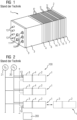
- FIG 1 shows a simplified schematic representation of a fuel cell module 1 known from the prior art, which has a fuel cell unit 2 and a resource supply unit 3 for supplying the fuel cell unit 2 with the resources.
- the fuel cell module 1 preferably has exactly one fuel cell unit 2 and exactly one resource supply unit 3 assigned to this fuel cell unit 2, ie the resource supply unit 3 only serves to supply this one assigned fuel cell unit 2 with resources.
- the fuel cell module 1 it is also possible, for example, for the fuel cell module 1 to have exactly one operating resource supply unit 3 and two or more fuel cell units 2 that are assigned only to this and are supplied with operating resources.
- the fuel cell unit 2 includes a stack 5 of PEM (polymer electrolyte membrane) fuel cells 5' and a stack 6 of humidification cells 6'.
- the stack 5 is cascaded and has two partial stacks with a stabilizing plate 15 arranged between them. Cascading enables very emission-free operation of the fuel cells.
- the fuel cell unit 2 and the resource supply unit 3 are connected to one another via a connecting plate 4 arranged between the two units.
- the fuel cell unit 2 additionally has an end plate 7, the stacks 5, 6 being arranged between the connecting plate 2 and the end plate 7.
- the end plate 7 and the connecting plate 4 are braced together by means of tie rods (not shown) and thus hold the stacks 5, 6 together.
- the resource supply unit 3 is also connected to the connection plate 4 and has a connection plate 9 with power connections 10 for tapping a current generated in the fuel cells 5 'from outside the fuel cell module 1, sensor connections 11 and resource connections 13 for the supply and removal of resources (oxygen, hydrogen, nitrogen) to or from the fuel cell module 1.
- the plates 4, 14, 15 have a number of plates running through the plates Figure 1 resource channels not shown.
- the plates 4, 7 close off the fuel cell unit 2 from the outside.
- the resource supply unit 3 includes auxiliary components for the operation of the fuel cell module 1, in particular valves for switching on and off the (external) resource supply, pressure sensors, temperature sensors and/or water separators.
- Sensors and actuators of the fuel cell module 1 are connected to a higher-level control and regulation device via corresponding connections in the connection plate 9 or end plate 7 and signal and control lines. Only the sensor connections 13 are shown as an example. Any busbars that run along the outside of the fuel cell unit 2 and lead the electricity generated by the fuel cells into the resource supply unit 3 are not shown.
- FIG 2 shows a fuel cell system 100 with several fuel cell modules 1 according to FIG 1 .
- the fuel cell modules 1 are connected to a common hydrogen supply 20 and a common oxygen supply 21 via the connections 13 for the supply of operating resources from outside. In a similar way, they can also be connected to a common nitrogen supply or cooling water supply, for example.
- a higher-level control and / or regulation device 200 is used to control and / or regulate all fuel cell modules 1 and is for this purpose, for example, with the sensor inputs 11 (see FIG 1 ) tied together.
- the entire module 1 To replace a defective fuel cell 5' of a fuel cell module 1, the entire module 1 must be separated from the fuel cell system 100 using the connections 10, 11, 13 and replaced. For this purpose, the entire fuel cell system 100 must be switched off and then switched on again. To reinstall a fuel cell module 1, the entire fuel cell system 100 must also be switched off and then switched on again.
- FIG 3 shows a fuel cell module 1 according to the invention, in comparison to FIG 1 the same components are provided with the same reference numerals.
- the connection plate 4 comprises a first sub-plate 4a and a second sub-plate 4b, which are detachable from one another in order to separate the fuel cell unit 2 from the resource supply unit 3.
- the fuel cell unit 2 is connected to the second partial plate 4b and the stacks 5, 6 are arranged between the second partial plate and the end plate 7.
- the second partial plate 4b and the end plate 7 are braced together in such a way that they hold the stacks 5, 6 together.
- the resource supply unit 3 is connected to the first sub-plate 4a.
- the fuel cell unit can therefore be exchanged very easily, with the resource supply unit 3 remaining connected to the fuel cell system 100 with its connections 10, 13.
- busbars that run along the outside of the fuel cell unit 2 and lead the electricity generated by the fuel cells 5 'into the resource supply unit 3.
- These busbars can, for example, be separated from or reconnected to busbars in the resource supply unit 3 via plug connections.
- elements for releasably connecting the two partial plates 4a, 4b and a seal between these two partial plates can, for example, consist of screw connections which are arranged on the outer edge of the partial plates 4a, 4b. Holes necessary for this can be arranged, for example, in an edge region of the partial plates 4a, 4b, which protrudes beyond an outer edge of the fuel cells 5 'or humidification cells 6'.
- resource channels run in a manner not shown in the stacking direction of the cells 5', 6', through the two partial plates 4a, 4b through.
- the fuel cell module 1 includes its own module control and / or regulation device 30, which is detachably attached to the fuel cell unit 2 and via control and / or signal lines, not shown in detail, which can be detached from the resource supply unit 3 and the fuel cell unit 2 and have actuators arranged therein. sensors is connected.
- the module control and/or regulation device 30 can therefore easily be replaced in the event of a defect.
- the module control and/or regulation device takes over essential functions of the higher-level control and/or regulation device 200 FIG 2 , so that there is no need for sensor outputs in the connection plate 9.
- the module control and/or regulation device 30 is designed to bring the fuel cell unit 2 into a safe state before disconnecting it from the resource supply unit 3 by means of a switch-off procedure and to bring the fuel cell unit 2 back into a safe state by means of a switch-on procedure after connecting it to the resource supply unit 3 to put into operation.
- the fuel cell module 1 includes a switchable electrical resistor 31 for electrically discharging the fuel cell unit 2 as part of the switch-off procedure.
- the fuel cell module 1 further comprises a cell voltage monitoring device 32, which is also detachably attached to the fuel cell unit 2 and is connected to fuel cells 5 of the fuel cell unit 2 via signal lines that can be detached from the fuel cell unit 2.
- the cell voltage monitoring device 32 can therefore also be easily replaced in the event of a defect.
- the module control and/or regulation device 30 in FIG 5 has on its outside a first control element 41 (eg a button) for starting the switch-off procedure and a second control element 42 (eg a button) for starting the switch-on procedure.
- a first display element 43 eg a signal lamp
- a second display element 44 eg a signal lamp
- a person can therefore start the switch-off procedure or switch-on procedure particularly easily on site at the fuel cell module 1 and receive feedback as to when they can safely separate the fuel cell unit 2 from the resource supply unit 3 or that the fuel cell module 1 after connecting the fuel cell unit 2 and Resource supply unit 3 is ready for operation again.
- the fuel cell module 1 usually has a nominal electrical power of at least 5 kW for maritime applications.
- an uncascaded stack can also be present.
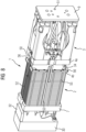
- FIG 4 shows the fuel cell module 1 of FIG 3 in a state in which the resource supply unit 3, the fuel cell unit 2, the module control and/or regulation device 30 and the cell voltage monitoring device 32 are separated from one another. You can also see operating medium channels 34 running through the partial plates 4a, 4b. Seals (not shown in detail) can be located between the partial plates 4a, 4b to seal the operating medium channels 34. Furthermore, tie rods 35 for bracing the partial plate 4b with the end plate 7 are shown schematically.
- FIG 5 shows a top view of the outside of the module control and / or regulation device 30 with the operating elements 41, 42 and the display elements 43, 44. Also visible are a touchscreen 45 for displaying status information and connector connections 46 for connecting connectors for signal and Control lines and for bus communication to a higher-level control and/or regulation device.
- the fuel cell unit 2 can be separated from the resource supply unit 3 and replaced, with the resource supply unit 3 remaining connected to the fuel cell system 100. This can be done while the fuel cell system 100 is in operation. It is not necessary to switch off and then switch on the entire fuel cell system 100 when an individual fuel cell unit 2 is replaced.
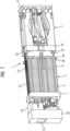
- FIG 7 and 8th show a fuel cell module 1 according to the invention in two different perspective views separate state in detail.
- Corresponding components are given the same reference numerals. To simplify the illustration, only holes 51 of the connections in the connection plate 9 are shown.
- busbars 52 running along the fuel cell unit 2, which can be connected to or detached from electrical connecting lines in the resource supply unit 3 via plug-in couplings 50.
- the module control and/or regulation device 30 now has a touchscreen 55 instead of separate operating and display elements. Also shown are tie rods 55 for bracing the plates 4b and 7 in order to hold the stacks 5 and 6 together.
- the two partial plates 4a, 4b can also have quick couplings in the operating medium channels 34 running through them.
- holes 56 for screw connections for releasably connecting the fuel cell unit 2 to the operating fluid supply unit 3 are shown on the outer edge of the partial plates 4a, 4b.
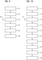
- FIG 9 is a process flow 60 for a separation of a fuel cell unit 2 from a resource supply unit 3 illustrated. The procedure is based on the exemplary embodiments of FIGS. 3 to 6 explained.
- the method starts during ongoing operation of the fuel cell system 100 in a step 61 with a switch-off command by an operator using the control element 41, alternatively also directly by the module control and / or regulation device 30 or the higher-level control and regulation device 200.
- This switch-off command is issued by the module control and/or regulation device 30 is recorded.
- the module control and/or regulation device 30 then automatically starts and runs through a switch-off procedure.
- the module control and/or regulation device 30 first separates the fuel cells 5' from the power connections 10 (and thus electrically from the fuel cell system 100) by means of a switch in a step 62 and switches the fuel cells 5' of the fuel cell module 1 to be switched off after the fuel cell module 1 has been switched off Reactants and handling of the operating gas spaces the discharge resistor 31.
- the module control and/or regulation device 30 carries out an inerting of the fuel cells 5′.
- This inerting includes evacuating (if necessary several times) and filling the gas spaces of the fuel cells with nitrogen and/or flushing with nitrogen until the hydrogen concentration falls below a predetermined limit.
- the coolant spaces of the fuel cell unit 2 are then emptied in a step 64.
- the module control and/or regulation device 30 signals a successful completion of the final procedure to an operator in a step 65 by appropriately activating the display element 43.
- the operator can then separate the module control and/or regulation device 30, the fuel cell unit 2 and the resource supply unit 3 from one another in a step 66.
- FIG 10 is a process flow 70 for a connection of a fuel cell unit 2 and a resource supply unit 3 illustrated. The procedure will be also based on the exemplary embodiments of FIGS. 3 to 6 explained.
- the method starts during ongoing operation of the fuel cell system 100 in a step 71 with a mechanical connection of the fuel cell unit 2 and the resource supply unit 3 by an operator.
- the module control and/or regulation device 30 is electrically and mechanically connected to the fuel cell unit 2 and the resource supply unit 3.
- the operator then generates a switch-on command in a step 72 by actuating the control element 42.
- This switch-on command is detected by the module control and/or regulation device 30.
- the module control and/or regulation device 30 then automatically starts and runs through a switch-on procedure.
- a first step 73 the correct connection of sensors and valves to the module control and/or regulation device 30 is checked.
- a proper connection of power conductors e.g. busbars that carry the current generated by the fuel cells is checked.
- the coolant spaces of the fuel cell unit 2 are filled with coolant (eg deionized water), which is supplied to the fuel cell module 1 from externally (eg via an auxiliary device as in the as yet unpublished European patent application No. 16163367.2 the applicant or directly via a resource supply of the connected fuel cell system) to the resource supply unit 3.
- coolant eg deionized water
- This can also include subsequent venting and/or degassing of the coolant spaces.
- the operating gas spaces of the fuel cells 5 are suitably prepared with inert gas, evacuation and/or purging in order to carry out a pressure maintenance test/leak test in a step 77 with different degrees of filling of the gas spaces of the fuel cell unit 2 (e.g. via an auxiliary device as in the as yet unpublished European patent application No. 16163367.2 the applicant or directly via a resource supply to the connected fuel cell system).
- the reactants can then be added in a step 78 and the electrochemical reaction can be checked, preferably using the open-circuit voltages.
- the coolant spaces of the module control and/or regulation device 30 signal a successful completion of the switch-on procedure to an operator in a step 79 by appropriately controlling the display element 44.
- the fuel cell module 2 can then be connected to the fuel cell system 100 in a step 80.
Landscapes
- Life Sciences & Earth Sciences (AREA)
- Engineering & Computer Science (AREA)
- Manufacturing & Machinery (AREA)
- Sustainable Development (AREA)
- Sustainable Energy (AREA)
- Chemical & Material Sciences (AREA)
- Chemical Kinetics & Catalysis (AREA)
- Electrochemistry (AREA)
- General Chemical & Material Sciences (AREA)
- Fuel Cell (AREA)
Claims (15)
- Module (1) de pile à combustible comprenant une unité (2) de pile à combustible et une unité (3) d'alimentation en agents de fonctionnement, pour l'alimentation de l'unité (2) de pile à combustibles en agents de fonctionnement, dans lequel l'unité (2) de pile à combustible a au moins un empilement (5) de piles (5') combustible, de préférence un empilement (5) en cascade de piles (5') à combustible, dans lequel l'unité (3) d'alimentation en agents de fonctionnement a des bornes (10) de courant pour la prise d'un courant produit dans les piles (5') à combustible de l'extérieur du module (1) de pile à combustible et des raccords (13) d'agents de fonctionnement pour l'apport d'agents de fonctionnement au module (2) de pile à combustible et pour leur évacuation du module de pile à combustible, dans lequel l'unité (2) de pile à combustible et l'unité (3) d'alimentation en agents de fonctionnement peuvent être séparées l'une de l'autre, dans lequel le module (1) de pile à combustible comprend, monté sur ou dans le module (1) de pile à combustible, un dispositif (30) de commande de module et/ou de régulation de module, qui est constitué pour, au moyen d'une procédure de mise hors circuit, mettre l'unité (2) de pile à combustible, avant une séparation de l'unité (3) d'alimentation en agents de fonctionnement, dans un état sécurisé et/ou pour mettre en fonctionnement, au moyen d'une procédure de mise en circuit, l'unité (2) de pile à combustible, après une liaison avec l'unité (3) d'alimentation en agents de fonctionnement.
- Module (1) de pile à combustible suivant la revendication 1, caractérisé en ce que le dispositif (30) de commande et/ou de régulation de module est fixé de manière amovible à l'unité (2) de pile à combustible ou à l'unité (3) d'alimentation en agents de fonctionnement et est relié, par des lignes de commande et/ou de signal pouvant être détachées de l'unité (3) d'alimentation en agents de fonctionnement et/ou de l'unité (2) de pile à combustible, à des actionneurs ou des capteurs, qui y sont montés respectivement.
- Module (1) de pile à combustible suivant l'une des revendications précédentes, caractérisé en ce qu'il comprend une résistance (31) électrique pouvant être mise en circuit pour la décharge électrique de l'unité (2) de pile à combustible.
- Module (1) de pile à combustible suivant l'une des revendications précédentes, caractérisé en ce qu'il a un ou plusieurs éléments (41, 42) de service pour faire débuter la procédure de mise hors circuit et/ou la procédure de mise en circuit et/ou un ou plusieurs éléments (43, 44) d'indication pour l'indication d'une fin couronnée de succès de la procédure de mise hors circuit et/ou de la procédure de mise en circuit.
- Module (1) de pile à combustible suivant l'une des revendications précédentes, caractérisé en ce que l'unité (2) de pile à combustible et l'unité (3) d'alimentation en agents de fonctionnement sont reliées entre elles par une plaque (4) de liaison montée entre les deux unités, dans lequel la plaque (4) de liaison comprend une première plaque (4a) partielle et une deuxième plaque (4b) partielle, qui peuvent être détachées l'une de l'autre, afin de séparer l'unité (2) de pile à combustible de l'unité (3) d'alimentation en agents de fonctionnement.
- Module (1) de pile à combustible suivant la revendication 5, caractérisé en ce que l'unité (2) de pile à combustible est reliée à la deuxième plaque (4b) partielle et a une plaque (7) d'extrémité, dans lequel le au moins un empilement (5) de piles (5') à combustible est disposé entre la deuxième plaque (4) partielle et la plaque (7) d'extrémité et dans lequel la deuxième plaque (4b) partielle et la plaque (7) d'extrémité sont bloquées entre elles, de manière à maintenir ensemble l'empilement (5) de pile (5') à combustible.
- Module (1) de pile à combustible suivant l'une des revendications 5 ou 6, caractérisé en ce que l'unité (3) d'alimentation en agents de fonctionnement est reliée à la première plaque (4a) partielle et comprend une plaque (9) de raccordement, qui a les raccords (13) d'agents de fonctionnement, de préférence également les bornes (10) de courant.
- Module (1) de pile à combustible suivant l'une des revendications 5 à 7, caractérisé en ce qu'un empilement (6) de piles (6') d'humidification est monté entre la deuxième plaque (4b) partielle et la plaque (7) d'extrémité, dans lequel la deuxième plaque (4b) partielle et la plaque (7) d'extrémité sont bloquées entre elles, de manière à maintenir ensemble en même temps, tant l'empilement (5) de piles (5') à combustible qu'également l'empilement (6) de piles (6') d'humidification.
- Module (1) de pile à combustible suivant l'une des revendications 5 à 8, caractérisé en ce que des canaux (34) d'agents de fonctionnement traversent les deux plaques (4a, 4b) partielles.
- Système (100) de piles à combustible comprenant plusieurs modules (1) de pile à combustible, chacun suivant l'une des revendications précédentes qui, pour l'alimentation en agents de fonctionnent, sont raccordés à une alimentation (20, 21) commune en agents de fonctionnement.
- Procédé pour faire fonctionner un système (100) de pile à combustible ayant plusieurs modules (1) de pile à combustible, chacun suivant l'une des revendications 1 à 9, que l'on alimente en agents de fonctionnement, à partir d'une alimentation (20, 21) commune en agents de fonctionnement, dans lequel, pour le remplacement d'une unité (2) de pile à combustible d'un module (1) de pile à combustible en fonctionnement courant du système (100) de pile à combustible, on met l'unité (2) de pile à combustible de ce module (1) de pile à combustible dans un état sécurisé, au moyen de la procédure de mise hors circuit et ensuite, on la sépare de l'unité (3) d'alimentation en agents de fonctionnement, dans lequel, après une séparation de l'unité (2) de pile à combustible de l'unité (3) d'alimentation en agents de fonctionnement, l'unité (3) d'alimentation en agents de fonctionnement reste raccordée au système (100) de pile à combustible.
- Procédé suivant la revendication 11, caractérisé en ce que la procédure de mise hors circuit comprend une décharge et une inertisation des piles (5') à combustible.
- Procédé pour faire fonctionner un système (100) de pile à combustible ayant plusieurs modules (1) de pile à combustible, chacun suivant l'une des revendications 1 à 9, que l'on alimente en agents de fonctionnement, à partir d'une alimentation (20, 21) commune en agents de fonctionnement, dans lequel, lors d'un fonctionnement en cours du système (100) de pile à combustible et alors que l'unité (3) d'alimentation en agents de fonctionnement est raccordée au système (100) de pile à combustible, on relie l'unité (2) de pile à combustible à l'unité (3) d'alimentation en agents de fonctionnement et on la met en fonctionnement au moyen de la procédure de mise en circuit.
- Procédé suivant la revendication 13, caractérisé en ce que la procédure de mise en circuit, comprend au moins l'un, de préférence tous les stades suivants :- contrôle d'un raccordement conforme aux prescriptions de capteurs et d'actionneurs au dispositif (30) de commande et/ou de régulation de module,- contrôle d'un raccordement conforme aux prescriptions de conducteurs (52) de courant pour la conduction d'un courant produit par l'unité (2) de pile à combustible,- remplissage par du réfrigérant d'espaces pour réfrigérant de l'unité (2) de pile à combustible,- remplissage par un gaz inerte d'espaces pour gaz de fonctionnement de l'unité (2) de pile à combustible,- contrôle d'étanchéité,- remplissage par des gaz de fonctionnement d'espaces pour gaz de fonctionnement de l'unité (2) de pile à combustible,- contrôle de la réaction électrochimique des piles (5') à combustible, de préférence à l'aide de tensions en marche à vide.
- Procédé suivant l'une des revendications 11 à 14, dans lequel, pour le remplacement d'une unité (2) de pile à combustible d'un module (1) de pile à combustible, on effectue d'abord le procédé suivant l'une des revendications 11 et 12, et ensuite le procédé suivant l'une des revendications 13 et 14.
Applications Claiming Priority (2)
| Application Number | Priority Date | Filing Date | Title |
|---|---|---|---|
| EP16002468.3A EP3324475A1 (fr) | 2016-11-18 | 2016-11-18 | Module de pile à combustible, système de pile à combustible et procédé de fonctionnement |
| PCT/EP2017/079306 WO2018091522A1 (fr) | 2016-11-18 | 2017-11-15 | Module de piles à combustible, système de piles à combustible et procédé de fonctionnement |
Publications (3)
| Publication Number | Publication Date |
|---|---|
| EP3520162A1 EP3520162A1 (fr) | 2019-08-07 |
| EP3520162B1 true EP3520162B1 (fr) | 2024-02-21 |
| EP3520162C0 EP3520162C0 (fr) | 2024-02-21 |
Family
ID=57389156
Family Applications (2)
| Application Number | Title | Priority Date | Filing Date |
|---|---|---|---|
| EP16002468.3A Withdrawn EP3324475A1 (fr) | 2016-11-18 | 2016-11-18 | Module de pile à combustible, système de pile à combustible et procédé de fonctionnement |
| EP17807756.6A Active EP3520162B1 (fr) | 2016-11-18 | 2017-11-15 | Module de pile à combustible, système de pile à combustible et procédé de fonctionnement |
Family Applications Before (1)
| Application Number | Title | Priority Date | Filing Date |
|---|---|---|---|
| EP16002468.3A Withdrawn EP3324475A1 (fr) | 2016-11-18 | 2016-11-18 | Module de pile à combustible, système de pile à combustible et procédé de fonctionnement |
Country Status (5)
| Country | Link |
|---|---|
| US (1) | US20190379081A1 (fr) |
| EP (2) | EP3324475A1 (fr) |
| KR (1) | KR102380246B1 (fr) |
| ES (1) | ES2985739T3 (fr) |
| WO (1) | WO2018091522A1 (fr) |
Families Citing this family (5)
| Publication number | Priority date | Publication date | Assignee | Title |
|---|---|---|---|---|
| DE102021105899A1 (de) * | 2021-03-11 | 2022-09-15 | Bayerische Motoren Werke Aktiengesellschaft | Vorrichtung und Verfahren zur Überprüfung des Inertisierungszustands eines Brennstoff-Bereitstellungssystems |
| AT524835A1 (de) * | 2021-10-29 | 2022-09-15 | Avl List Gmbh | Brennstoffzellensystem für einen stationären Betrieb zum Erzeugen von elektrischem Strom mit einer Prüfvorrichtung für eine Funktionsprüfung |
| DE102022209602A1 (de) * | 2022-09-14 | 2024-03-14 | Robert Bosch Gesellschaft mit beschränkter Haftung | Brennstoffzellensystem und Spülverfahren zum Inertisieren eines Brennstoffzellensystems |
| EP4455368B1 (fr) * | 2023-04-25 | 2026-03-18 | Topsoe A/S | Empilement de soc comprenant une plaque de connexion |
| AU2024262077A1 (en) * | 2023-04-25 | 2025-11-06 | Topsoe A/S | Soc stack comprising connection plate |
Citations (1)
| Publication number | Priority date | Publication date | Assignee | Title |
|---|---|---|---|---|
| DE102004059776A1 (de) * | 2004-09-17 | 2006-04-06 | Deutsches Zentrum für Luft- und Raumfahrt e.V. | Brennstoffzellensystem |
Family Cites Families (9)
| Publication number | Priority date | Publication date | Assignee | Title |
|---|---|---|---|---|
| CA2461745A1 (fr) | 2001-09-27 | 2003-04-10 | Siemens Aktiengesellschaft | Section de pile a combustible |
| US20060166053A1 (en) * | 2001-11-21 | 2006-07-27 | Badding Michael E | Solid oxide fuel cell assembly with replaceable stack and packet modules |
| CN1647307A (zh) * | 2002-04-22 | 2005-07-27 | 普腾能源系统有限公司 | 用于提供模块化电源的方法和装置 |
| DE102004003670B4 (de) * | 2003-12-12 | 2008-02-14 | Mtu Friedrichshafen Gmbh | Brennstoffzellenanordnung mit mehreren mittels eines Verteilermoduls zusammengeschalteten Brennstoffzellenmodulen |
| US7875397B2 (en) * | 2003-12-15 | 2011-01-25 | Utc Power Corporation | Permeable inlet fuel gas distributor for fuel cells |
| DE102004004623B4 (de) | 2004-01-29 | 2005-12-29 | Siemens Ag | Brennstoffzelleneinrichtung für ein U-Boot |
| DE102010028961A1 (de) * | 2010-05-12 | 2011-11-17 | Trumpf Werkzeugmaschinen Gmbh + Co. Kg | Modulares Brennstoffzellensystem |
| JP2013182690A (ja) * | 2012-02-29 | 2013-09-12 | Nissan Motor Co Ltd | 燃料電池システム |
| KR101403173B1 (ko) * | 2012-07-25 | 2014-06-11 | 주식회사 효성 | 연료전지 공용분배기 |
-
2016
- 2016-11-18 EP EP16002468.3A patent/EP3324475A1/fr not_active Withdrawn
-
2017
- 2017-11-15 EP EP17807756.6A patent/EP3520162B1/fr active Active
- 2017-11-15 WO PCT/EP2017/079306 patent/WO2018091522A1/fr not_active Ceased
- 2017-11-15 US US16/462,477 patent/US20190379081A1/en not_active Abandoned
- 2017-11-15 ES ES17807756T patent/ES2985739T3/es active Active
- 2017-11-15 KR KR1020197017348A patent/KR102380246B1/ko active Active
Patent Citations (1)
| Publication number | Priority date | Publication date | Assignee | Title |
|---|---|---|---|---|
| DE102004059776A1 (de) * | 2004-09-17 | 2006-04-06 | Deutsches Zentrum für Luft- und Raumfahrt e.V. | Brennstoffzellensystem |
Also Published As
| Publication number | Publication date |
|---|---|
| KR102380246B1 (ko) | 2022-03-29 |
| ES2985739T3 (es) | 2024-11-07 |
| EP3520162A1 (fr) | 2019-08-07 |
| US20190379081A1 (en) | 2019-12-12 |
| WO2018091522A1 (fr) | 2018-05-24 |
| KR20190077101A (ko) | 2019-07-02 |
| EP3520162C0 (fr) | 2024-02-21 |
| EP3324475A1 (fr) | 2018-05-23 |
Similar Documents
| Publication | Publication Date | Title |
|---|---|---|
| EP3520162B1 (fr) | Module de pile à combustible, système de pile à combustible et procédé de fonctionnement | |
| DE102011076981B4 (de) | Batteriesystem, Kraftfahrzeug mit diesem Batteriesystem und Verfahren zur Herstellung einer Betriebsbereitschaft bei einem Kraftfahrzeug mit diesem Batteriesystem | |
| DE102014210358A1 (de) | Brennstoffzellenstapel mit einer dummyzelle | |
| EP2056388A1 (fr) | Procédé destiné à éviter des inclusions d'impuretés sous forme de gaz dans au moins une chambre à gaz d'une cellule de combustible lors d'un temps de repos et cellule de combustible dotée de moyens destinés à l'exécution du procédé | |
| WO2021073881A1 (fr) | Procédé de mise en service d'un empilement de cellules élémentaires | |
| EP2422397B1 (fr) | Système de piles à combustible | |
| EP3476000A1 (fr) | Dispositif de conversion d'énergie, en particulier pile à combustible ou électrolyseur | |
| EP1338068B1 (fr) | Dispositif d'alimentation en courant continu et procede de mise hors-circuit d'un bloc de piles a combustible | |
| DE102008015350A1 (de) | Modular aufgebauter Brennstoffzellenstapel | |
| EP3324476A1 (fr) | Module de pile à combustible, système de pile à combustible et procédé de fonctionnement | |
| WO2022161595A1 (fr) | Procédé de fonctionnement d'un empilement électrolytique | |
| DE102015224088A1 (de) | Verfahren zur Reparatur eines Brennstoffzellenstapels | |
| DE102019217219A1 (de) | Zellanordnung zur Erzeugung und Verdichtung von Wasserstoff | |
| DE102020215349A1 (de) | Verfahren zum Starten von mehreren Brennstoffzellensystemen in einer Vorrichtung | |
| EP4279636B1 (fr) | Dispositif d'électrolyse | |
| DE102023205693A1 (de) | Elektrochemische Anlage | |
| EP3437151B1 (fr) | Procédé d'échange d'un empilement de piles à combustibles dans un système de piles à combustible | |
| DE2129134C3 (de) | Brennstoffzellenaggregat | |
| DE102023207092A1 (de) | Verfahren zum Betreiben einer elektrochemischen Anlage, elektrochemische Anlage | |
| DE102018200485A1 (de) | Wassergebundenes Fahrzeug mit einer Energieversorgungseinrichtung | |
| WO2002009217A2 (fr) | Procede permettant de faire fonctionner une pile a combustible | |
| DE102019002945A1 (de) | Brennstoffzellensystem mit einem Brennstoffzellenstapel | |
| DE102024203606A1 (de) | Verfahren zum Betreiben eines Brennstoffzellensystems | |
| DE102024116577A1 (de) | Brennstoffzellensystem | |
| DE102023207098A1 (de) | Verfahren zum Betreiben einer elektrochemischen Anlage, elektrochemische Anlage |
Legal Events
| Date | Code | Title | Description |
|---|---|---|---|
| STAA | Information on the status of an ep patent application or granted ep patent |
Free format text: STATUS: UNKNOWN |
|
| STAA | Information on the status of an ep patent application or granted ep patent |
Free format text: STATUS: THE INTERNATIONAL PUBLICATION HAS BEEN MADE |
|
| PUAI | Public reference made under article 153(3) epc to a published international application that has entered the european phase |
Free format text: ORIGINAL CODE: 0009012 |
|
| STAA | Information on the status of an ep patent application or granted ep patent |
Free format text: STATUS: REQUEST FOR EXAMINATION WAS MADE |
|
| 17P | Request for examination filed |
Effective date: 20190503 |
|
| AK | Designated contracting states |
Kind code of ref document: A1 Designated state(s): AL AT BE BG CH CY CZ DE DK EE ES FI FR GB GR HR HU IE IS IT LI LT LU LV MC MK MT NL NO PL PT RO RS SE SI SK SM TR |
|
| AX | Request for extension of the european patent |
Extension state: BA ME |
|
| DAV | Request for validation of the european patent (deleted) | ||
| DAX | Request for extension of the european patent (deleted) | ||
| STAA | Information on the status of an ep patent application or granted ep patent |
Free format text: STATUS: EXAMINATION IS IN PROGRESS |
|
| 17Q | First examination report despatched |
Effective date: 20200415 |
|
| RAP1 | Party data changed (applicant data changed or rights of an application transferred) |
Owner name: SIEMENS ENERGY GLOBAL GMBH & CO. KG |
|
| REG | Reference to a national code |
Ref country code: DE Ref legal event code: R079 Free format text: PREVIOUS MAIN CLASS: H01M0008246500 Ipc: H01M0008043020 Ref country code: DE Ref legal event code: R079 Ref document number: 502017015861 Country of ref document: DE Free format text: PREVIOUS MAIN CLASS: H01M0008246500 Ipc: H01M0008043020 |
|
| GRAP | Despatch of communication of intention to grant a patent |
Free format text: ORIGINAL CODE: EPIDOSNIGR1 |
|
| STAA | Information on the status of an ep patent application or granted ep patent |
Free format text: STATUS: GRANT OF PATENT IS INTENDED |
|
| RIC1 | Information provided on ipc code assigned before grant |
Ipc: H01M 8/249 20160101ALI20230927BHEP Ipc: H01M 8/2465 20160101ALI20230927BHEP Ipc: H01M 8/04303 20160101ALI20230927BHEP Ipc: H01M 8/04302 20160101AFI20230927BHEP |
|
| INTG | Intention to grant announced |
Effective date: 20231011 |
|
| GRAS | Grant fee paid |
Free format text: ORIGINAL CODE: EPIDOSNIGR3 |
|
| GRAA | (expected) grant |
Free format text: ORIGINAL CODE: 0009210 |
|
| STAA | Information on the status of an ep patent application or granted ep patent |
Free format text: STATUS: THE PATENT HAS BEEN GRANTED |
|
| AK | Designated contracting states |
Kind code of ref document: B1 Designated state(s): AL AT BE BG CH CY CZ DE DK EE ES FI FR GB GR HR HU IE IS IT LI LT LU LV MC MK MT NL NO PL PT RO RS SE SI SK SM TR |
|
| REG | Reference to a national code |
Ref country code: GB Ref legal event code: FG4D Free format text: NOT ENGLISH |
|
| REG | Reference to a national code |
Ref country code: CH Ref legal event code: EP |
|
| REG | Reference to a national code |
Ref country code: DE Ref legal event code: R096 Ref document number: 502017015861 Country of ref document: DE |
|
| REG | Reference to a national code |
Ref country code: IE Ref legal event code: FG4D Free format text: LANGUAGE OF EP DOCUMENT: GERMAN |
|
| U01 | Request for unitary effect filed |
Effective date: 20240222 |
|
| U07 | Unitary effect registered |
Designated state(s): AT BE BG DE DK EE FI FR IT LT LU LV MT NL PT SE SI Effective date: 20240301 |
|
| REG | Reference to a national code |
Ref country code: LT Ref legal event code: MG9D |
|
| PG25 | Lapsed in a contracting state [announced via postgrant information from national office to epo] |
Ref country code: IS Free format text: LAPSE BECAUSE OF FAILURE TO SUBMIT A TRANSLATION OF THE DESCRIPTION OR TO PAY THE FEE WITHIN THE PRESCRIBED TIME-LIMIT Effective date: 20240621 |
|
| PG25 | Lapsed in a contracting state [announced via postgrant information from national office to epo] |
Ref country code: GR Free format text: LAPSE BECAUSE OF FAILURE TO SUBMIT A TRANSLATION OF THE DESCRIPTION OR TO PAY THE FEE WITHIN THE PRESCRIBED TIME-LIMIT Effective date: 20240522 |
|
| PG25 | Lapsed in a contracting state [announced via postgrant information from national office to epo] |
Ref country code: RS Free format text: LAPSE BECAUSE OF FAILURE TO SUBMIT A TRANSLATION OF THE DESCRIPTION OR TO PAY THE FEE WITHIN THE PRESCRIBED TIME-LIMIT Effective date: 20240521 Ref country code: HR Free format text: LAPSE BECAUSE OF FAILURE TO SUBMIT A TRANSLATION OF THE DESCRIPTION OR TO PAY THE FEE WITHIN THE PRESCRIBED TIME-LIMIT Effective date: 20240221 |
|
| PG25 | Lapsed in a contracting state [announced via postgrant information from national office to epo] |
Ref country code: RS Free format text: LAPSE BECAUSE OF FAILURE TO SUBMIT A TRANSLATION OF THE DESCRIPTION OR TO PAY THE FEE WITHIN THE PRESCRIBED TIME-LIMIT Effective date: 20240521 Ref country code: IS Free format text: LAPSE BECAUSE OF FAILURE TO SUBMIT A TRANSLATION OF THE DESCRIPTION OR TO PAY THE FEE WITHIN THE PRESCRIBED TIME-LIMIT Effective date: 20240621 Ref country code: HR Free format text: LAPSE BECAUSE OF FAILURE TO SUBMIT A TRANSLATION OF THE DESCRIPTION OR TO PAY THE FEE WITHIN THE PRESCRIBED TIME-LIMIT Effective date: 20240221 Ref country code: GR Free format text: LAPSE BECAUSE OF FAILURE TO SUBMIT A TRANSLATION OF THE DESCRIPTION OR TO PAY THE FEE WITHIN THE PRESCRIBED TIME-LIMIT Effective date: 20240522 |
|
| PG25 | Lapsed in a contracting state [announced via postgrant information from national office to epo] |
Ref country code: PL Free format text: LAPSE BECAUSE OF FAILURE TO SUBMIT A TRANSLATION OF THE DESCRIPTION OR TO PAY THE FEE WITHIN THE PRESCRIBED TIME-LIMIT Effective date: 20240221 |
|
| PG25 | Lapsed in a contracting state [announced via postgrant information from national office to epo] |
Ref country code: PL Free format text: LAPSE BECAUSE OF FAILURE TO SUBMIT A TRANSLATION OF THE DESCRIPTION OR TO PAY THE FEE WITHIN THE PRESCRIBED TIME-LIMIT Effective date: 20240221 |
|
| PG25 | Lapsed in a contracting state [announced via postgrant information from national office to epo] |
Ref country code: SM Free format text: LAPSE BECAUSE OF FAILURE TO SUBMIT A TRANSLATION OF THE DESCRIPTION OR TO PAY THE FEE WITHIN THE PRESCRIBED TIME-LIMIT Effective date: 20240221 |
|
| PG25 | Lapsed in a contracting state [announced via postgrant information from national office to epo] |
Ref country code: CZ Free format text: LAPSE BECAUSE OF FAILURE TO SUBMIT A TRANSLATION OF THE DESCRIPTION OR TO PAY THE FEE WITHIN THE PRESCRIBED TIME-LIMIT Effective date: 20240221 |
|
| PG25 | Lapsed in a contracting state [announced via postgrant information from national office to epo] |
Ref country code: SK Free format text: LAPSE BECAUSE OF FAILURE TO SUBMIT A TRANSLATION OF THE DESCRIPTION OR TO PAY THE FEE WITHIN THE PRESCRIBED TIME-LIMIT Effective date: 20240221 |
|
| PG25 | Lapsed in a contracting state [announced via postgrant information from national office to epo] |
Ref country code: SM Free format text: LAPSE BECAUSE OF FAILURE TO SUBMIT A TRANSLATION OF THE DESCRIPTION OR TO PAY THE FEE WITHIN THE PRESCRIBED TIME-LIMIT Effective date: 20240221 Ref country code: SK Free format text: LAPSE BECAUSE OF FAILURE TO SUBMIT A TRANSLATION OF THE DESCRIPTION OR TO PAY THE FEE WITHIN THE PRESCRIBED TIME-LIMIT Effective date: 20240221 Ref country code: RO Free format text: LAPSE BECAUSE OF FAILURE TO SUBMIT A TRANSLATION OF THE DESCRIPTION OR TO PAY THE FEE WITHIN THE PRESCRIBED TIME-LIMIT Effective date: 20240221 Ref country code: CZ Free format text: LAPSE BECAUSE OF FAILURE TO SUBMIT A TRANSLATION OF THE DESCRIPTION OR TO PAY THE FEE WITHIN THE PRESCRIBED TIME-LIMIT Effective date: 20240221 |
|
| REG | Reference to a national code |
Ref country code: ES Ref legal event code: FG2A Ref document number: 2985739 Country of ref document: ES Kind code of ref document: T3 Effective date: 20241107 |
|
| REG | Reference to a national code |
Ref country code: DE Ref legal event code: R097 Ref document number: 502017015861 Country of ref document: DE |
|
| PLBE | No opposition filed within time limit |
Free format text: ORIGINAL CODE: 0009261 |
|
| STAA | Information on the status of an ep patent application or granted ep patent |
Free format text: STATUS: NO OPPOSITION FILED WITHIN TIME LIMIT |
|
| U20 | Renewal fee for the european patent with unitary effect paid |
Year of fee payment: 8 Effective date: 20241127 |
|
| 26N | No opposition filed |
Effective date: 20241122 |
|
| REG | Reference to a national code |
Ref country code: CH Ref legal event code: PL |
|
| PG25 | Lapsed in a contracting state [announced via postgrant information from national office to epo] |
Ref country code: MC Free format text: LAPSE BECAUSE OF FAILURE TO SUBMIT A TRANSLATION OF THE DESCRIPTION OR TO PAY THE FEE WITHIN THE PRESCRIBED TIME-LIMIT Effective date: 20240221 |
|
| REG | Reference to a national code |
Ref country code: CH Ref legal event code: PL |
|
| GBPC | Gb: european patent ceased through non-payment of renewal fee |
Effective date: 20241115 |
|
| PG25 | Lapsed in a contracting state [announced via postgrant information from national office to epo] |
Ref country code: CH Free format text: LAPSE BECAUSE OF NON-PAYMENT OF DUE FEES Effective date: 20241130 |
|
| PG25 | Lapsed in a contracting state [announced via postgrant information from national office to epo] |
Ref country code: GB Free format text: LAPSE BECAUSE OF NON-PAYMENT OF DUE FEES Effective date: 20241115 |
|
| PG25 | Lapsed in a contracting state [announced via postgrant information from national office to epo] |
Ref country code: IE Free format text: LAPSE BECAUSE OF NON-PAYMENT OF DUE FEES Effective date: 20241115 |
|
| U20 | Renewal fee for the european patent with unitary effect paid |
Year of fee payment: 9 Effective date: 20251126 |
|
| PGFP | Annual fee paid to national office [announced via postgrant information from national office to epo] |
Ref country code: NO Payment date: 20251120 Year of fee payment: 9 |
|
| PGFP | Annual fee paid to national office [announced via postgrant information from national office to epo] |
Ref country code: ES Payment date: 20251209 Year of fee payment: 9 |
|
| PG25 | Lapsed in a contracting state [announced via postgrant information from national office to epo] |
Ref country code: HU Free format text: LAPSE BECAUSE OF FAILURE TO SUBMIT A TRANSLATION OF THE DESCRIPTION OR TO PAY THE FEE WITHIN THE PRESCRIBED TIME-LIMIT; INVALID AB INITIO Effective date: 20171115 |
|
| PG25 | Lapsed in a contracting state [announced via postgrant information from national office to epo] |
Ref country code: CY Free format text: LAPSE BECAUSE OF FAILURE TO SUBMIT A TRANSLATION OF THE DESCRIPTION OR TO PAY THE FEE WITHIN THE PRESCRIBED TIME-LIMIT; INVALID AB INITIO Effective date: 20171115 |