EP3520185B1 - Klemme zum einsetzen eines biegeelastischen strangs in einen behälter zur aufnahme des stranges über eine öffnung - Google Patents
Klemme zum einsetzen eines biegeelastischen strangs in einen behälter zur aufnahme des stranges über eine öffnung Download PDFInfo
- Publication number
- EP3520185B1 EP3520185B1 EP17780843.3A EP17780843A EP3520185B1 EP 3520185 B1 EP3520185 B1 EP 3520185B1 EP 17780843 A EP17780843 A EP 17780843A EP 3520185 B1 EP3520185 B1 EP 3520185B1
- Authority
- EP
- European Patent Office
- Prior art keywords
- clamp
- strand
- housing
- receptacle
- segment
- Prior art date
- Legal status (The legal status is an assumption and is not a legal conclusion. Google has not performed a legal analysis and makes no representation as to the accuracy of the status listed.)
- Active
Links
Images


Classifications
-
- H—ELECTRICITY
- H02—GENERATION; CONVERSION OR DISTRIBUTION OF ELECTRIC POWER
- H02G—INSTALLATION OF ELECTRIC CABLES OR LINES, OR OF COMBINED OPTICAL AND ELECTRIC CABLES OR LINES
- H02G1/00—Methods or apparatus specially adapted for installing, maintaining, repairing or dismantling electric cables or lines
- H02G1/06—Methods or apparatus specially adapted for installing, maintaining, repairing or dismantling electric cables or lines for laying cables, e.g. laying apparatus on vehicle
- H02G1/08—Methods or apparatus specially adapted for installing, maintaining, repairing or dismantling electric cables or lines for laying cables, e.g. laying apparatus on vehicle through tubing or conduit, e.g. rod or draw wire for pushing or pulling
- H02G1/085—Methods or apparatus specially adapted for installing, maintaining, repairing or dismantling electric cables or lines for laying cables, e.g. laying apparatus on vehicle through tubing or conduit, e.g. rod or draw wire for pushing or pulling using portable tools
-
- B—PERFORMING OPERATIONS; TRANSPORTING
- B65—CONVEYING; PACKING; STORING; HANDLING THIN OR FILAMENTARY MATERIAL
- B65H—HANDLING THIN OR FILAMENTARY MATERIAL, e.g. SHEETS, WEBS, CABLES
- B65H2402/00—Constructional details of the handling apparatus
- B65H2402/40—Details of frames, housings or mountings of the whole handling apparatus
- B65H2402/41—Portable or hand-held apparatus
- B65H2402/414—Manual tools for filamentary material, e.g. for mounting or removing a bobbin, measuring tension or splicing
-
- B—PERFORMING OPERATIONS; TRANSPORTING
- B65—CONVEYING; PACKING; STORING; HANDLING THIN OR FILAMENTARY MATERIAL
- B65H—HANDLING THIN OR FILAMENTARY MATERIAL, e.g. SHEETS, WEBS, CABLES
- B65H51/00—Forwarding filamentary material
- B65H51/18—Gripping devices with linear motion
Definitions
- the application is in the field of installing cables of dimensions small enough to be handled by hand. It concerns in particular a tool for handling an elastic strand in bending, for example a cable or a cable pulling needle, with the aim of inserting the strand into a receptacle which may be a tube, or a storage reel.
- a person To insert a strand by hand into a receptacle such as a tube or a spool, a person must grasp the strand by hand at a certain distance from the orifice of the receptacle, this distance corresponding to an insertion pitch, exert a certain pressure on the grasped strand in order to prevent it from slipping in the hand, approach the hand to the orifice in order to push the pitch of strand into it, and then release the strand in order to reposition the hand at the same distance from the orifice corresponding to an insertion pitch, and so on.
- Inserting a strand into any receptacle is a difficult operation to perform with bare hands, as soon as the strand encounters a little resistance when inserted into the receptacle, or if the total length of the strand to be inserted is great.
- the pressure exerted by the hand must be sufficient to lock the section of strand in the clamp. Since a slippage of the strand in the groove is not necessarily perceptible, a person will tend to exert more pressure than necessary in order to be sure to prevent this slippage, which is tiring over a long period.
- the US patent US 3,549,128 discloses a clamp sliding in a guide, also having the disadvantages described above.
- the US Patent 1,959,490 also discloses a clamp for pushing and pulling a strand.
- the insertion step must be large, or the movement must be repeated quickly. But if the step is too large, or the movement is too fast, the clamp cannot prevent the strand from bending rather than entering the hole, which may damage or even break the strand.
- One of the aims of the invention is to remedy these drawbacks of the state of the art.
- the invention improves the situation by means of a clamp according to claim 1.
- the strand When the first part of the segment that is housed in the clamp is kept deformed in bending, the strand can no longer slide longitudinally in the clamp.
- the pressure required to block the strand is therefore that sufficient to deform the strand.
- This necessary pressure is very easy to control visually by the operator, because it corresponds to a movement of the blocking means.
- the pressure preventing longitudinal sliding of the strand is a compression of the strand on a segment left straight, that is to say without deforming it, therefore without movement perceptible to the naked eye of the blocking means between a contact position without applied pressure, and a pressure position.
- the guide means surrounds the strand on a second part of the segment housed in the clamp, this second part, which is not held by the locking means, is nevertheless prevented from bending when the clamp with the blocked strand is pushed towards the orifice, even if a great deal of resistance is encountered when inserting through the orifice.
- the strand since the strand is elastic in bending, it returns to its initial shape, generally rectilinear, as soon as the pressure on the locking means is removed, which allows the strand to slide freely in the housing of the clamp, without a specific mechanism being necessary to release the strand from the locking means, such as a spring.
- the clamp can be easily repositioned at its starting point after inserting a pitch of strand, without any particular effort being necessary to loosen the clamp.
- the insertion operation is thus made more efficient.
- the locking means comprises a fixed lower jaw, comprising the first part of the housing, and a movable upper jaw, capable of entering at least partially into the first part of the housing to cover the first part of the housed segment, the upper jaw having a non-rectilinear profile so as to impart a non-rectilinear shape to the first part of the housed segment when the jaws are brought closer to each other.
- the locking means is actuated by pressure exerted by a hand enclosing the two jaws.
- the jaws are sized to fit together in a hand of ordinary size, preferably in the palm. Thus, it is sufficient to squeeze the hand to actuate the locking means.
- the sensitivity of the hand means that the movement of the jaws towards each other is very easily detected. It is therefore easy for the operator, on the one hand, to know when the locking means is actuated, and on the other hand, to correctly dose the necessary force without tiring himself.
- the jaws By releasing the hand pressure, the jaws move away in a movement detected by the hand's sensitivity. The operator then knows that the strand has become straight again, that it is no longer blocked and that it can therefore slide in the clamp.
- the upper jaw can take at least one position remote from the lower jaw, where the housing is open.
- the opening of the clamp housing becomes completely free, which allows the strand segment to be removed from the clamp at the end of the insertion operation, or the strand segment to be housed in the clamp at the beginning of the operation. of insertion.
- the upper jaw is connected to the clamp by a hinge.
- a hinge ensures the alignment of the jaws facing each other.
- the upper jaw is connected to the clamp by a flexible membrane.
- the membrane and the jaws may form a single piece.
- this piece may be made of a plastic material with properties such that the jaws are sufficiently hard, and the membrane, being thin, is sufficiently flexible to allow movement of the upper jaw relative to the lower jaw.
- the upper jaw fits into the lower jaw in a piston-like manner.
- the upper jaw is a separate part from the rest of the clamp, and no connecting part is necessary, such as a hinge or a membrane. It acts as a piston in the lower jaw which forms with at least part of the opening of the housing the piston jacket. To prevent the operator from misplacing the detachable upper jaw, it can however be connected to the clamp by a chain or a cord.
- the guide means is a guide tube.
- the portion of the housing that is not included in the locking means is included in the guide means, which has the shape of a tube.
- the length of the clamp that is not occupied by the locking means serves as a guide tube for the clamp.
- the outer diameter of the guide tube is adapted so that the tube enters through the orifice of the receptacle.
- the guide tube can slide in the orifice of the receptacle.
- the insertion pitch of the strand corresponds approximately to the length of the guide tube.
- the receptacle is a tube for receiving the strand, and where the inner diameter of the guide tube is adapted so that the receiving tube slides in the guide tube.
- the guide tube is adapted so that the clamp functions to rewind a strand into a receptacle such as, for example, a reel extended by a leader tube serving to facilitate the introduction of the strand into a sheath when it leaves the reel.
- the leader tube of the reel constitutes the receiving tube of the receptacle in the sense of the invention.
- the opening of the housing in its second part is a longitudinal slot in the guide tube, not parallel to the guide tube.
- the slot is not parallel to the guide tube, it is also not parallel to the housing or to the housed strand.
- the housed strand cannot therefore accidentally exit the housing during the step-by-step insertion operation. Only express manipulation by the operator can force the strand to position itself facing the slot to exit through the opening.
- the slot follows a spiral over at least a portion of the length of the guide tube.
- the spiral shape allows one end of the strand to be inserted into the guide tube by rotating the clamp around the strand, without having to deform the strand.
- the slot follows a sinusoidal shape over at least a portion of the length of the guide tube.
- the sinusoid shape if not very pronounced, makes it easy to push one end of the strand into the guide tube by deforming it slightly so that it adopts the shape.
- the invention also relates to a multitude of other shapes suitable for the slot, which are non-parallel to the guide tube.
- strand is used to designate the filiform object to be inserted into a receptacle using the clamp according to the invention.
- the clamp according to the invention can be used for all types of elastic filiform objects in bending. It is understood that the term strand includes, for example, electric cables, optical cables, or cable pulling needles, made of any material, having this mechanical characteristic of elasticity in bending.
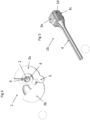
- the clamp 1 is longitudinal in shape and is traversed along its entire length by a housing 2 for a strand, from a first opening of the housing 2 at one end of the clamp to a second opening at the other end.
- the strand can therefore protrude from both ends.
- the guide means 4 has the shape of a tube in the illustrated examples, and is hereinafter called a guide tube. But other embodiments are possible with other shapes for the guide means 4, depending on the type of opening of the receptacle in which the strand is intended to be inserted.
- the locking means 3 consists of two jaws 3a and 3b connected by a hinge 5. This hinge can be replaced by any other means capable of guiding the upper jaw 3b towards the lower jaw 3a.
- the lower jaw 3a is fixed and integral with the guide tube 4 with which it can form a single piece, while the upper jaw 3b is movable relative to the rest of the clamp 1.
- the portion of the housing 2a located in the locking means 3 is in the lower jaw 3a, and comprises an opening facing the upper jaw 3b.
- This opening of the housing 2 extends in the form of a slot 6, over the entire length of the part of the housing 2b located in the guide tube 4.
- the slot 6 can be rectilinear without being parallel, for example adopting the shape of a slight spiral starting from the opening of the part 2a at its junction with the part 2b of the housing 2, to join the free end of the guide tube 4 by turning around it.
- the slot 6 can also be sinusoidal without turning around the guide tube 4, as shown in figure 2 .
- the strand can slide as long as the locking means is only partially closed, that is to say as long as the jaws 3a and 3b are sufficiently distant from each other so that the housing 2 remains rectilinear over its entire length, including in its part 2a.
- figures 2 And 4 illustrate such a position of the partially closed jaws.
- the operator places the two jaws 3a and 3b in the palm of his hand.
- the jaws adopt a substantially cylindrical shape, ergonomically adapted to one-handed operation.
- the figure 3 clearly illustrates this cylindrical shape of the locking means 3 of the clamp 1, when it is in the closed position.
- the strand is blocked and can no longer slide, because the housing 2 in which it is housed is no longer rectilinear.
- the contact surface 7 of the upper jaw 3b with the strand has a non-rectilinear profile which pushes a segment of the strand to the bottom of the lower jaw 3a, deforming it in bending.
- the profile is sinusoidal but other shapes are possible, such as for example saw teeth.
- the profile of the contact surface of the lower jaw 3a be identical, so that both jaws touch the strand on the deformed segment, which has the advantage of increasing the locking force of the strand in the clamp 1 in the closed position.
- Another way of increasing the locking force is to increase the adhesion of the contact surface of at least one of the jaws, by a suitable material, such as rubber for example.
- the operator can thus alternate very quickly between a position where the strand is blocked in the clamp, and a position where it slides freely, simply by holding the clamp locking means in the palm of the hand, and tightening or loosening the clamp without letting go, which is one of the easiest and least tiring muscular movements for the human body.
- the guide tube 4 it becomes very easy to insert the strand into a receptacle, coordinating the alternating tightening and loosening movement of the palm of the hand with a back and forth movement towards the orifice of the receptacle.
- the tubular shape of the guide means 4 allows the clamp 1 to slide relative to the orifice of the receptacle, which prevents a portion of the strand located between the clamp and the receptacle from being exposed to the air when the strand is pushed towards the receptacle, in which case this portion of the strand would risk bending or even breaking.
- the receptacle is also a tube, called an insertion tube to distinguish it from the guide tube.
- An insertion tube is for example a sheath intended to receive a cable if the strand is a cable, or a cable pulling needle starter tube, if the strand is a needle.
- the outer diameter of the guide tube 4 must be slightly smaller than that of the receptacle orifice in order to slide easily into it.
- the inner diameter of the guide tube 4 i.e. the inner diameter of the part 2b of the housing 2 which is in the guide tube, must be slightly greater than the outer diameter of the insertion tube, so that the latter slides easily therein.
- An insertion step corresponds to the length of the sliding movement of the guide tube 4 in the orifice of the receptacle, or of the sliding movement of the orifice of the insertion tube in the guide tube 4, depending on the variant. It is understood that the length of this insertion step can therefore reach the length of the guide tube 4.
- the operator grasps the locking means 3 with the palm of his hand and positions the free end of the guide tube 4 in the orifice of the receptacle, or he positions the orifice of the insertion tube in the free end of the guide tube 4, depending on the variant.
- FIG. 5 shows a view of a clamp according to another embodiment of the invention.
- the clamp 1b differs from the clamp 1 by the locking means 3c.
- the locking means 3c also comprises a lower lower jaw 3d forming a single piece with the guide means 4, and a movable upper jaw 3e, but the latter is not connected to the lower jaw 3d by a hinge or a flexible membrane.
- the upper jaw 3e is a detached part of the clamp, adapted to slide into the opening of the lower jaw 3d, like a piston in its jacket. To open the clamp and accommodate the strand, it is sufficient to completely remove the upper jaw 3e from the clamp.
- a chain or cord, not illustrated, can be added between the upper jaw 3e and the clamp to prevent the loss of the small part that constitutes the upper jaw 3e.
- This embodiment may be suitable for a small model of clamp, where a hinge would be more fragile.
- the locking means may be held between the fingers, rather than in the palm of the hand, for example with the thumb positioned on the upper jaw 3e and one or more fingers positioned under the lower jaw 3d.
- the components of the clamp according to the invention can actually be easily dimensioned and adapted according to the dimensions and the cross-sectional shape of the strand to be inserted.
- the width of the housing 2 is a function of the width of the strand, and the shape of the housing 2 can be configured substantially circular or substantially rectangular, depending on whether the strand is of circular or rather flattened cross-section.
Landscapes
- Surgical Instruments (AREA)
- Clamps And Clips (AREA)
Claims (13)
- Klemme zum Einsetzen eines biegeelastischen Strangs durch eine Öffnung in einen Behälter, wobei die Klemme eine längliche Aufnahme (2) beinhaltet, die dazu fähig ist, ein Segment des Strangs aufzunehmen, und in der der Strang gleiten kann, wobei die Klemme (1, 1b) Folgendes beinhaltet:· ein Blockiermittel (3, 3c), das einen ersten Teil (2a) der Aufnahme beinhaltet,· ein Führungsmittel (4), das einen zweiten Teil (2b) der Aufnahme beinhaltet, wobei das Führungsmittel (4) dazu konfiguriert ist, einen zweiten Teil des aufgenommenen Segments mindestens teilweise zu umgeben, und dazu konfiguriert ist, die Klemme in Richtung der Öffnung des Behälters zu führen,Klemme, bei der das Blockiermittel (3, 3c) zum Biegeverformen eines ersten Teils des aufgenommenen Segments fähig ist, wenn ein Außendruck auf das Blockiermittel ausgeübt wird, das dazu bestimmt ist, mit dem Strang verwendet zu werden, dessen elastische Kraft dem ersten Teil des Segments seine ursprüngliche Form zurückgibt, wenn der Außendruck nicht mehr ausgeübt wird, wobei das Gleiten des Strangs durch die Biegeverformung des ersten Teils des aufgenommenen Segments blockiert wird, und wobei das Blockiermittel (3, 3c) ferner Folgendes beinhaltet:· eine feststehende untere Backe (3a, 3d), die mit dem Führungsmittel (4), mit welchem sie einstückig ausgebildet ist, fest verbunden ist und den ersten Teil (2a) der Aufnahme beinhaltet und· eine in Bezug auf den Rest der Klemme bewegliche obere Backe (3b, 3e), die dazu fähig ist, zu der unteren Backe (3a, 3d) geführt zu werden und mindestens teilweise in den ersten Teil (2a) der Aufnahmen einzutreten, um den ersten Teil des aufgenommenen Segments zu bedecken, wobei die obere Backe (3b, 3e) ein nicht geradliniges Profil aufweist, um dem ersten Teil des aufgenommenen Segments eine nicht geradlinige Form zu verleihen, wenn die Backen ((3a, 3b), (3d, 3e)) einander angenähert werden,Klemme, bei der untere Kontaktpunkte auf der unteren Backe (3a, 3d) und obere Kontaktpunkte auf der oberen Backe (3b, 3e) angeordnet sind, wobei die Kontaktpunkte dazu konfiguriert sind, abwechselnd unter und über dem ersten Teil des aufgenommenen Segments angeordnet zu sein, um einen Druck auf die Unterseite und auf die Oberseite des ersten Teils des aufgenommenen Segments auszuüben,und Klemme, bei der die Backen ((3a, 3b), (3e, 3d)) dazu konfiguriert sind, sich voneinander zu entfernen, wenn der Außendruck nicht mehr ausgeübt wird, wobei die obere Backe (3b, 3e) dazu fähig ist, durch eine elastische Kraft des Strangs, der seine geradlinige Form wieder einnimmt, von der unteren Backe (3a, 3d) weggedrückt zu werden.
- Klemme nach Anspruch 1, wobei das Blockiermittel (3) durch einen Druck betätigbar ist, der durch eine Hand ausgeübt wird, die die zwei Backen (3a, 3b) umschließt.
- Klemme nach Anspruch 1, wobei die obere Backe (3b) mindestens eine von der unteren Backe (3a) entfernte Position einnehmen kann, in der die Aufnahme (2, 2a) offen ist.
- Klemme nach einem der Ansprüche 1 bis 3, wobei die obere Backe (3b) mit dem Rest der Klemme (1) durch ein Scharnier (5) verbunden ist.
- Klemme nach einem der Ansprüche 1 bis 3, wobei die obere Backe (3b) mit dem Rest der Klemme (1) durch eine flexible Membran verbunden ist.
- Klemme nach einem der Ansprüche 1 bis 3, wobei die obere Backe (3e) kolbenartig in die untere Backe (3d) eingreift.
- Klemme nach einem der vorhergehenden Ansprüche, wobei das Führungsmittel (4) ein Führungsrohr ist.
- System, das einen Behälter und eine Klemme nach Anspruch 7 beinhaltet, wobei der Außendurchmesser des Führungsrohrs (4) dazu angepasst ist, dass das Rohr durch die Öffnung des Behälters eintritt.
- System, das einen Behälter und eine Klemme nach Anspruch 7 beinhaltet, wobei der Behälter ein Rohr zur Aufnahme des Strangs ist und wobei der Innendurchmesser des Führungsrohrs (4) dazu angepasst ist, dass das Aufnahmerohr in dem Führungsrohr gleitet.
- Klemme nach Anspruch 7 oder System nach den Ansprüchen 8 oder 9, wobei die Öffnung der Aufnahme (2) in ihrem zweiten Teil (2b) ein Längsschlitz (6) in dem Führungsrohr (4) ist, der zu dem Führungsrohr nicht parallel ist.
- Klemme oder System nach Anspruch 10, wobei der Schlitz über mindestens einen Teil der Länge des Führungsrohrs (4) spiralförmig ist.
- Klemme oder System nach Anspruch 10, wobei der Schlitz (6) über mindestens einen Teil der Länge des Führungsrohrs (4) sinusförmig ist.
- Verfahren zum Einsetzen eines biegeelastischen Strangs durch eine Öffnung eines Behälters mit Hilfe einer Klemme (1, 1b) nach Anspruch 1, beinhaltend einen Schritt des Positionierens eines Strangsegments in einer Aufnahme (2, 2a, 2b) der Klemme und mindestens eine Wiederholung des Einsetzens einer Stranglänge, beinhaltend die folgenden Schritte:· Ausüben, mit der Hand, eines Drucks auf das Blockiermittel (3, 3c), was zur Folge hat, dass der Strang in der Klemme blockiert wird, indem ein Teil des Strangsegments verformt wird,· In-Kontakt-Bringen eines Endes des Führungsmittels (4) mit der Öffnung des Behälters,· Annähern der Klemme und der Öffnung über eine Entfernung, die der effektiven Länge des Führungsmittels (4) und der Einsetzlänge entspricht,· Wegnehmen des Drucks auf das Blockiermittel (3, 3c), was zur Folge hat, dass das Gleiten des Strangs ermöglicht wird, ohne die Aufnahme (2a) zu öffnen,· erneutes Positionieren durch Entfernen der Klemme von der Öffnung über eine Entfernung, die der Einsetzlänge entspricht.
Applications Claiming Priority (2)
| Application Number | Priority Date | Filing Date | Title |
|---|---|---|---|
| FR1659457A FR3057115A1 (fr) | 2016-09-30 | 2016-09-30 | Pince pour inserer un brin elastique en flexion dans un receptacle destine a recevoir le brin par un orifice |
| PCT/FR2017/052582 WO2018060585A1 (fr) | 2016-09-30 | 2017-09-26 | Pince pour insérer un brin élastique en flexion dans un réceptacle destiné à recevoir le brin par un orifice |
Publications (2)
| Publication Number | Publication Date |
|---|---|
| EP3520185A1 EP3520185A1 (de) | 2019-08-07 |
| EP3520185B1 true EP3520185B1 (de) | 2024-12-11 |
Family
ID=57796494
Family Applications (1)
| Application Number | Title | Priority Date | Filing Date |
|---|---|---|---|
| EP17780843.3A Active EP3520185B1 (de) | 2016-09-30 | 2017-09-26 | Klemme zum einsetzen eines biegeelastischen strangs in einen behälter zur aufnahme des stranges über eine öffnung |
Country Status (4)
| Country | Link |
|---|---|
| US (1) | US10985540B2 (de) |
| EP (1) | EP3520185B1 (de) |
| FR (1) | FR3057115A1 (de) |
| WO (1) | WO2018060585A1 (de) |
Citations (3)
| Publication number | Priority date | Publication date | Assignee | Title |
|---|---|---|---|---|
| US1959490A (en) * | 1931-08-31 | 1934-05-22 | Mistelski Theodor | Wire pushing and pulling tool |
| DE2926986A1 (de) * | 1979-07-04 | 1981-01-22 | Johann Henkenjohann | Hilfsmittel zum hochziehen einer last, wie rollaeden u.dgl. |
| EP0285699B1 (de) * | 1987-04-01 | 1992-04-08 | Werner Cielker | Zange zum Verschieben von flexiblem Strangmaterial |
Family Cites Families (12)
| Publication number | Priority date | Publication date | Assignee | Title |
|---|---|---|---|---|
| US2448384A (en) * | 1947-07-15 | 1948-08-31 | Meinzinger Dale | Handgrip for fishing lines |
| US3312128A (en) * | 1965-05-07 | 1967-04-04 | Lawrence W Wasson | Wire gripper |
| US3549128A (en) | 1968-08-14 | 1970-12-22 | Nicholas S Homiak | Tool for pushing or pulling a cable through a pipe or the like |
| US3789484A (en) | 1972-12-22 | 1974-02-05 | G & H Technology | Electrical contact terminal hand tool |
| US5431370A (en) * | 1994-03-28 | 1995-07-11 | Verkuylen; Donald G. | Fish tape tugger |
| US5544926A (en) * | 1995-01-30 | 1996-08-13 | Ravencroft; Gary N. | Shaft gripper for pulling an arrow |
| US5806902A (en) * | 1996-12-18 | 1998-09-15 | Kliest; William R. | Grip for rope manipulation |
| US6749179B2 (en) | 2002-03-13 | 2004-06-15 | Board Of Regents, The University Of Texas System | Devices and methods for placing wiring into split loom tubing |
| US6698979B1 (en) * | 2003-02-19 | 2004-03-02 | David M. Ambrose | Wire and cable installation tool |
| US7104287B1 (en) * | 2005-07-26 | 2006-09-12 | Thomas Schmitz | Wire-untwisting tool |
| WO2007124076A1 (en) * | 2006-04-21 | 2007-11-01 | Abbott Laboratories | Guidewire handling device |
| US20160032950A1 (en) * | 2014-07-31 | 2016-02-04 | Ta Instruments-Waters L.L.C. | Tension clamp devices |
-
2016
- 2016-09-30 FR FR1659457A patent/FR3057115A1/fr active Pending
-
2017
- 2017-09-26 WO PCT/FR2017/052582 patent/WO2018060585A1/fr not_active Ceased
- 2017-09-26 EP EP17780843.3A patent/EP3520185B1/de active Active
- 2017-09-26 US US16/335,945 patent/US10985540B2/en active Active
Patent Citations (3)
| Publication number | Priority date | Publication date | Assignee | Title |
|---|---|---|---|---|
| US1959490A (en) * | 1931-08-31 | 1934-05-22 | Mistelski Theodor | Wire pushing and pulling tool |
| DE2926986A1 (de) * | 1979-07-04 | 1981-01-22 | Johann Henkenjohann | Hilfsmittel zum hochziehen einer last, wie rollaeden u.dgl. |
| EP0285699B1 (de) * | 1987-04-01 | 1992-04-08 | Werner Cielker | Zange zum Verschieben von flexiblem Strangmaterial |
Also Published As
| Publication number | Publication date |
|---|---|
| WO2018060585A1 (fr) | 2018-04-05 |
| FR3057115A1 (fr) | 2018-04-06 |
| US20190222006A1 (en) | 2019-07-18 |
| US10985540B2 (en) | 2021-04-20 |
| EP3520185A1 (de) | 2019-08-07 |
Similar Documents
| Publication | Publication Date | Title |
|---|---|---|
| CH644049A5 (fr) | Manche destine a etre utilise en liaison avec un outil en forme de ''l''. | |
| FR2929826A1 (fr) | Accessoire pour appareil d'aspiration equipe d'un peigne et d'un organe de degagement de poils et ensemble d'aspiration comportant un tel accessoire | |
| WO2007129175A2 (fr) | Pince a verrouillage | |
| FR3025433A1 (fr) | Dispositif de retrait d'un capuchon de protection d'une aiguille de seringue | |
| EP3523211B1 (de) | Vorrichtung zum verpacken eines objekts und entsprechendes verfahren zur extraktion | |
| EP3212094B1 (de) | Beidhändiger träger für einen nahtfaden | |
| EP3793471A1 (de) | Vorrichtung zum halten und freigeben eines gegenstandes, entsprechende anordnung und freigabeverfahren | |
| FR2741830A1 (fr) | Pince d'usinage a fonctions multiples | |
| FR2749752A1 (fr) | Dispositif de pliage et de maintien plie d'un implant intraoculaire souple | |
| EP3520185B1 (de) | Klemme zum einsetzen eines biegeelastischen strangs in einen behälter zur aufnahme des stranges über eine öffnung | |
| FR2808990A1 (fr) | Procede et instrument de tracheotomie | |
| EP0865880B1 (de) | Mehrzweckzange | |
| EP2938286B1 (de) | Anordnung mit mindestens einem implantat, einer greifvorrichtung und einem element zur verfolgung des implantats sowie verfahren zur verfolgbaren handhabung des implantats solch einer anordnung | |
| EP2006962A1 (de) | Spender- und Crimpzange für Verkabelungszubehör zum Aufcrimpen auf ein Kabel | |
| EP2860823A1 (de) | Werkzeug um eine Klemme anzuschliessen oder zu trennen. | |
| WO2008116985A2 (fr) | Outil de préhension, de transport et de pose de dispositifs dentaires | |
| KR20170003390U (ko) | 집게 | |
| WO2003043154A1 (fr) | Nouveau dispositif d'attache pour conducteurs electriques | |
| CA2225791C (fr) | Dispositif de pliage et de maintien plie d'un implant intraoculaire souple | |
| WO2002003795A1 (fr) | Degorgeoir universel a embout polyvalent et a dispositif de tirage | |
| FR2481595A1 (fr) | Pince pour ligaturer des appareils d'orthopedie dentaire | |
| FR3000380A1 (fr) | Ensemble du type comprenant au moins un implant, un prehenseur, et un element de tracabilite de l'implant, et procede de manipulation de maniere tracable de l'implant d'un tel ensemble | |
| FR3020003A1 (fr) | Pince a circlips | |
| FR2848656A1 (fr) | Emballage pour cordon de nettoyage de canons d'armes a feu | |
| FR2835360A1 (fr) | Outil d'engainage d'au moins un cable dans une gaine fendue longitudinalement, et dispositif d'engainage comportant un tel outil |
Legal Events
| Date | Code | Title | Description |
|---|---|---|---|
| STAA | Information on the status of an ep patent application or granted ep patent |
Free format text: STATUS: UNKNOWN |
|
| STAA | Information on the status of an ep patent application or granted ep patent |
Free format text: STATUS: THE INTERNATIONAL PUBLICATION HAS BEEN MADE |
|
| PUAI | Public reference made under article 153(3) epc to a published international application that has entered the european phase |
Free format text: ORIGINAL CODE: 0009012 |
|
| STAA | Information on the status of an ep patent application or granted ep patent |
Free format text: STATUS: REQUEST FOR EXAMINATION WAS MADE |
|
| 17P | Request for examination filed |
Effective date: 20190426 |
|
| AK | Designated contracting states |
Kind code of ref document: A1 Designated state(s): AL AT BE BG CH CY CZ DE DK EE ES FI FR GB GR HR HU IE IS IT LI LT LU LV MC MK MT NL NO PL PT RO RS SE SI SK SM TR |
|
| AX | Request for extension of the european patent |
Extension state: BA ME |
|
| DAV | Request for validation of the european patent (deleted) | ||
| DAX | Request for extension of the european patent (deleted) | ||
| RAP1 | Party data changed (applicant data changed or rights of an application transferred) |
Owner name: ORANGE |
|
| STAA | Information on the status of an ep patent application or granted ep patent |
Free format text: STATUS: EXAMINATION IS IN PROGRESS |
|
| 17Q | First examination report despatched |
Effective date: 20200908 |
|
| RAP3 | Party data changed (applicant data changed or rights of an application transferred) |
Owner name: ORANGE |
|
| GRAP | Despatch of communication of intention to grant a patent |
Free format text: ORIGINAL CODE: EPIDOSNIGR1 |
|
| STAA | Information on the status of an ep patent application or granted ep patent |
Free format text: STATUS: GRANT OF PATENT IS INTENDED |
|
| INTG | Intention to grant announced |
Effective date: 20240716 |
|
| GRAS | Grant fee paid |
Free format text: ORIGINAL CODE: EPIDOSNIGR3 |
|
| GRAA | (expected) grant |
Free format text: ORIGINAL CODE: 0009210 |
|
| STAA | Information on the status of an ep patent application or granted ep patent |
Free format text: STATUS: THE PATENT HAS BEEN GRANTED |
|
| AK | Designated contracting states |
Kind code of ref document: B1 Designated state(s): AL AT BE BG CH CY CZ DE DK EE ES FI FR GB GR HR HU IE IS IT LI LT LU LV MC MK MT NL NO PL PT RO RS SE SI SK SM TR |
|
| REG | Reference to a national code |
Ref country code: GB Ref legal event code: FG4D Free format text: NOT ENGLISH |
|
| REG | Reference to a national code |
Ref country code: CH Ref legal event code: EP |
|
| REG | Reference to a national code |
Ref country code: DE Ref legal event code: R096 Ref document number: 602017086717 Country of ref document: DE |
|
| REG | Reference to a national code |
Ref country code: IE Ref legal event code: FG4D Free format text: LANGUAGE OF EP DOCUMENT: FRENCH |
|
| REG | Reference to a national code |
Ref country code: LT Ref legal event code: MG9D |
|
| PG25 | Lapsed in a contracting state [announced via postgrant information from national office to epo] |
Ref country code: HR Free format text: LAPSE BECAUSE OF FAILURE TO SUBMIT A TRANSLATION OF THE DESCRIPTION OR TO PAY THE FEE WITHIN THE PRESCRIBED TIME-LIMIT Effective date: 20241211 |
|
| PG25 | Lapsed in a contracting state [announced via postgrant information from national office to epo] |
Ref country code: FI Free format text: LAPSE BECAUSE OF FAILURE TO SUBMIT A TRANSLATION OF THE DESCRIPTION OR TO PAY THE FEE WITHIN THE PRESCRIBED TIME-LIMIT Effective date: 20241211 |
|
| PG25 | Lapsed in a contracting state [announced via postgrant information from national office to epo] |
Ref country code: BG Free format text: LAPSE BECAUSE OF FAILURE TO SUBMIT A TRANSLATION OF THE DESCRIPTION OR TO PAY THE FEE WITHIN THE PRESCRIBED TIME-LIMIT Effective date: 20241211 |
|
| REG | Reference to a national code |
Ref country code: NL Ref legal event code: MP Effective date: 20241211 |
|
| PG25 | Lapsed in a contracting state [announced via postgrant information from national office to epo] |
Ref country code: ES Free format text: LAPSE BECAUSE OF FAILURE TO SUBMIT A TRANSLATION OF THE DESCRIPTION OR TO PAY THE FEE WITHIN THE PRESCRIBED TIME-LIMIT Effective date: 20241211 |
|
| PG25 | Lapsed in a contracting state [announced via postgrant information from national office to epo] |
Ref country code: NO Free format text: LAPSE BECAUSE OF FAILURE TO SUBMIT A TRANSLATION OF THE DESCRIPTION OR TO PAY THE FEE WITHIN THE PRESCRIBED TIME-LIMIT Effective date: 20250311 |
|
| PG25 | Lapsed in a contracting state [announced via postgrant information from national office to epo] |
Ref country code: LV Free format text: LAPSE BECAUSE OF FAILURE TO SUBMIT A TRANSLATION OF THE DESCRIPTION OR TO PAY THE FEE WITHIN THE PRESCRIBED TIME-LIMIT Effective date: 20241211 Ref country code: GR Free format text: LAPSE BECAUSE OF FAILURE TO SUBMIT A TRANSLATION OF THE DESCRIPTION OR TO PAY THE FEE WITHIN THE PRESCRIBED TIME-LIMIT Effective date: 20250312 |
|
| PG25 | Lapsed in a contracting state [announced via postgrant information from national office to epo] |
Ref country code: RS Free format text: LAPSE BECAUSE OF FAILURE TO SUBMIT A TRANSLATION OF THE DESCRIPTION OR TO PAY THE FEE WITHIN THE PRESCRIBED TIME-LIMIT Effective date: 20250311 |
|
| PG25 | Lapsed in a contracting state [announced via postgrant information from national office to epo] |
Ref country code: NL Free format text: LAPSE BECAUSE OF FAILURE TO SUBMIT A TRANSLATION OF THE DESCRIPTION OR TO PAY THE FEE WITHIN THE PRESCRIBED TIME-LIMIT Effective date: 20241211 |
|
| REG | Reference to a national code |
Ref country code: AT Ref legal event code: MK05 Ref document number: 1751138 Country of ref document: AT Kind code of ref document: T Effective date: 20241211 |
|
| PG25 | Lapsed in a contracting state [announced via postgrant information from national office to epo] |
Ref country code: SM Free format text: LAPSE BECAUSE OF FAILURE TO SUBMIT A TRANSLATION OF THE DESCRIPTION OR TO PAY THE FEE WITHIN THE PRESCRIBED TIME-LIMIT Effective date: 20241211 |
|
| PG25 | Lapsed in a contracting state [announced via postgrant information from national office to epo] |
Ref country code: PL Free format text: LAPSE BECAUSE OF FAILURE TO SUBMIT A TRANSLATION OF THE DESCRIPTION OR TO PAY THE FEE WITHIN THE PRESCRIBED TIME-LIMIT Effective date: 20241211 |
|
| PG25 | Lapsed in a contracting state [announced via postgrant information from national office to epo] |
Ref country code: IS Free format text: LAPSE BECAUSE OF FAILURE TO SUBMIT A TRANSLATION OF THE DESCRIPTION OR TO PAY THE FEE WITHIN THE PRESCRIBED TIME-LIMIT Effective date: 20250411 |
|
| PG25 | Lapsed in a contracting state [announced via postgrant information from national office to epo] |
Ref country code: PT Free format text: LAPSE BECAUSE OF FAILURE TO SUBMIT A TRANSLATION OF THE DESCRIPTION OR TO PAY THE FEE WITHIN THE PRESCRIBED TIME-LIMIT Effective date: 20250411 |
|
| PG25 | Lapsed in a contracting state [announced via postgrant information from national office to epo] |
Ref country code: EE Free format text: LAPSE BECAUSE OF FAILURE TO SUBMIT A TRANSLATION OF THE DESCRIPTION OR TO PAY THE FEE WITHIN THE PRESCRIBED TIME-LIMIT Effective date: 20241211 |
|
| PG25 | Lapsed in a contracting state [announced via postgrant information from national office to epo] |
Ref country code: AT Free format text: LAPSE BECAUSE OF FAILURE TO SUBMIT A TRANSLATION OF THE DESCRIPTION OR TO PAY THE FEE WITHIN THE PRESCRIBED TIME-LIMIT Effective date: 20241211 Ref country code: RO Free format text: LAPSE BECAUSE OF FAILURE TO SUBMIT A TRANSLATION OF THE DESCRIPTION OR TO PAY THE FEE WITHIN THE PRESCRIBED TIME-LIMIT Effective date: 20241211 |
|
| PG25 | Lapsed in a contracting state [announced via postgrant information from national office to epo] |
Ref country code: SK Free format text: LAPSE BECAUSE OF FAILURE TO SUBMIT A TRANSLATION OF THE DESCRIPTION OR TO PAY THE FEE WITHIN THE PRESCRIBED TIME-LIMIT Effective date: 20241211 |
|
| PG25 | Lapsed in a contracting state [announced via postgrant information from national office to epo] |
Ref country code: CZ Free format text: LAPSE BECAUSE OF FAILURE TO SUBMIT A TRANSLATION OF THE DESCRIPTION OR TO PAY THE FEE WITHIN THE PRESCRIBED TIME-LIMIT Effective date: 20241211 |
|
| PG25 | Lapsed in a contracting state [announced via postgrant information from national office to epo] |
Ref country code: IT Free format text: LAPSE BECAUSE OF FAILURE TO SUBMIT A TRANSLATION OF THE DESCRIPTION OR TO PAY THE FEE WITHIN THE PRESCRIBED TIME-LIMIT Effective date: 20241211 |
|
| PG25 | Lapsed in a contracting state [announced via postgrant information from national office to epo] |
Ref country code: SE Free format text: LAPSE BECAUSE OF FAILURE TO SUBMIT A TRANSLATION OF THE DESCRIPTION OR TO PAY THE FEE WITHIN THE PRESCRIBED TIME-LIMIT Effective date: 20241211 |
|
| REG | Reference to a national code |
Ref country code: DE Ref legal event code: R097 Ref document number: 602017086717 Country of ref document: DE |
|
| PG25 | Lapsed in a contracting state [announced via postgrant information from national office to epo] |
Ref country code: DK Free format text: LAPSE BECAUSE OF FAILURE TO SUBMIT A TRANSLATION OF THE DESCRIPTION OR TO PAY THE FEE WITHIN THE PRESCRIBED TIME-LIMIT Effective date: 20241211 |
|
| PGFP | Annual fee paid to national office [announced via postgrant information from national office to epo] |
Ref country code: DE Payment date: 20250820 Year of fee payment: 9 |
|
| PGFP | Annual fee paid to national office [announced via postgrant information from national office to epo] |
Ref country code: GB Payment date: 20250820 Year of fee payment: 9 |
|
| PLBE | No opposition filed within time limit |
Free format text: ORIGINAL CODE: 0009261 |
|
| STAA | Information on the status of an ep patent application or granted ep patent |
Free format text: STATUS: NO OPPOSITION FILED WITHIN TIME LIMIT |
|
| PGFP | Annual fee paid to national office [announced via postgrant information from national office to epo] |
Ref country code: FR Payment date: 20250820 Year of fee payment: 9 |
|
| 26N | No opposition filed |
Effective date: 20250912 |