EP3520303B1 - Procédé de communication sans fil pour transmettre une indication de ressource de signal de référence - Google Patents
Procédé de communication sans fil pour transmettre une indication de ressource de signal de référence Download PDFInfo
- Publication number
- EP3520303B1 EP3520303B1 EP17784477.6A EP17784477A EP3520303B1 EP 3520303 B1 EP3520303 B1 EP 3520303B1 EP 17784477 A EP17784477 A EP 17784477A EP 3520303 B1 EP3520303 B1 EP 3520303B1
- Authority
- EP
- European Patent Office
- Prior art keywords
- csi
- resource
- wireless communication
- communication method
- information
- Prior art date
- Legal status (The legal status is an assumption and is not a legal conclusion. Google has not performed a legal analysis and makes no representation as to the accuracy of the status listed.)
- Active
Links
Images







Classifications
-
- H—ELECTRICITY
- H04—ELECTRIC COMMUNICATION TECHNIQUE
- H04L—TRANSMISSION OF DIGITAL INFORMATION, e.g. TELEGRAPHIC COMMUNICATION
- H04L5/00—Arrangements affording multiple use of the transmission path
- H04L5/003—Arrangements for allocating sub-channels of the transmission path
- H04L5/0048—Allocation of pilot signals, i.e. of signals known to the receiver
-
- H—ELECTRICITY
- H04—ELECTRIC COMMUNICATION TECHNIQUE
- H04J—MULTIPLEX COMMUNICATION
- H04J1/00—Frequency-division multiplex systems
- H04J1/02—Details
-
- H—ELECTRICITY
- H04—ELECTRIC COMMUNICATION TECHNIQUE
- H04J—MULTIPLEX COMMUNICATION
- H04J13/00—Code division multiplex systems
- H04J13/16—Code allocation
-
- H—ELECTRICITY
- H04—ELECTRIC COMMUNICATION TECHNIQUE
- H04L—TRANSMISSION OF DIGITAL INFORMATION, e.g. TELEGRAPHIC COMMUNICATION
- H04L5/00—Arrangements affording multiple use of the transmission path
- H04L5/0091—Signalling for the administration of the divided path, e.g. signalling of configuration information
- H04L5/0094—Indication of how sub-channels of the path are allocated
-
- H—ELECTRICITY
- H04—ELECTRIC COMMUNICATION TECHNIQUE
- H04W—WIRELESS COMMUNICATION NETWORKS
- H04W72/00—Local resource management
- H04W72/20—Control channels or signalling for resource management
- H04W72/23—Control channels or signalling for resource management in the downlink direction of a wireless link, i.e. towards a terminal
-
- H—ELECTRICITY
- H04—ELECTRIC COMMUNICATION TECHNIQUE
- H04W—WIRELESS COMMUNICATION NETWORKS
- H04W76/00—Connection management
- H04W76/20—Manipulation of established connections
- H04W76/27—Transitions between radio resource control [RRC] states
-
- H—ELECTRICITY
- H04—ELECTRIC COMMUNICATION TECHNIQUE
- H04L—TRANSMISSION OF DIGITAL INFORMATION, e.g. TELEGRAPHIC COMMUNICATION
- H04L5/00—Arrangements affording multiple use of the transmission path
- H04L5/003—Arrangements for allocating sub-channels of the transmission path
- H04L5/0053—Allocation of signalling, i.e. of overhead other than pilot signals
Definitions
- the present invention generally relates to a wireless communication method and, more particularly, to a method of multiplexing Channel State Information-Reference Signal (CSI-RS), Zero-Power (ZP) CSI-RS, and Interference Measurement Resource (IMR) resources in a wireless communication system.
- CSI-RS Channel State Information-Reference Signal
- ZP Zero-Power
- IMR Interference Measurement Resource
- FIGs. 1A , 1B , 1C , and 1D are diagrams showing resource elements (REs) mapped to 2, 4, 8, and 1-port CSI-RS, respectively, according to the conventional LTE standard. As shown in FIGs. 1A-1D , one axis designates a frequency domain and the other axis designates a time domain.
- REs resource elements
- Each block corresponds to the RE in a resource block (RB) and the hatched REs with the AP number are mapped to the APs for CSI-RS transmission.
- CSI-RS resources are multiplexed using Frequency Division Multiplexing (FDM), Time Division Multiplexing (TDM), and Code Division Multiplexing (CDM) for power boosting.
- FDM Frequency Division Multiplexing
- TDM Time Division Multiplexing
- CDM Code Division Multiplexing
- 1-port CSI-RS transmission multiple CSI-RS resources are multiplexed using FDM and TDM.
- the AP numbers "15” and "16” are mapped to two REs.
- the AP numbers "15" to "18” are mapped to four REs.
- the AP numbers "15" to "22” are mapped to eight REs.
- resource density of the CSI-RS resource is one RE per AP for each RB (1RE/AP/RB).
- FIGs. 2A and 2B are diagrams showing the REs mapped to each AP for 2 and 1-port CSI-RS transmission, respectively, according to the LTE-A standard.
- the CSI-RS resource configuration of the 1-port CSI-RS under the conventional LTE standard may cause a large amount of CSI-RS overhead more than necessary.
- transmission efficiency in the 1-port CSI-RS transmission using a beam selection-based precoding method may decrease, as described below.
- FIG. 3 shows an example operation of CSI feedback when "k” is 4.
- a base station transmits four beamformed (BF) CSI-RSs.
- the UE receives the BF CSI-RSs, the UE transmit an index (CSI-RS resource indicator (CRI)) for the most appropriate BF CSI-RS and CSI feedback information corresponding to the most appropriate BF CSI-RS to the BS.
- CRI CSI-RS resource indicator
- the BS can acquire angular information of transmission beams, but it may be sufficient to transmit BF CSI-RSs using the 1-port.
- the 1-port CSI-RS transmission may not be efficient because the resource density of the 1-port CSI-RS is doubled as the resource density of 2, 4, 8, 12, and 16-port CSI-RS.
- the LTE-A standard supports a zero-power (ZP) CSI-RS scheme for high accurate CSI estimation.
- ZP zero-power
- the RE(s) designated as the ZP CSI-RS is muted. This makes it possible to improve accuracy of the CSI estimation on the muted RE(s).
- a non-zero-power (NZP) CSI-RS may be transmitted from a serving cell and CSI-RSs may not be transmitted from adjacent cells (the ZP CSI-RS may be applied in the adjacent cells).
- the conventional ZP CSI-RS may be notified using the REs mapped to the 4-port CSI-RS configurations. That is, the ZP CSI-RS resources can be designated only in a unit of four REs.
- PDSCH Physical Downlink Shared Channel
- US 2016/227519 A1 discloses transmitting resource indication for Zero-Power Reference Signals (ZP RSs) and/or Interference Measurement Resources (IMR) in the form of a bitmap.
- ZP RSs Zero-Power Reference Signals
- IMR Interference Measurement Resources
- FIG. 4 illustrates a wireless communications system 1 according to one or more embodiments of the present invention.
- the wireless communication system 1 includes a user equipment (UE) 10, a base stations (BS) 20, and a core network 30.
- the wireless communication system 1 may be an LTE/LTE-Advanced (LTE-A) system, New Radio (NR), or other systems.
- LTE-A LTE/LTE-Advanced
- NR New Radio
- the wireless communication system 1 is not limited to the specific configurations described herein and may be any type of wireless communication system.
- the BS 20 may communicate uplink (UL) and downlink (DL) signals with the UE 10 in a cell 21.
- the DL and UL signals may include control information and user data.
- the BS 20 may communicate DL and UL signals with the core network 30 through backhaul links 31.
- the BS 20 may be Evolved NodeB (eNB).
- the BS 20 includes one or more antennas, a communication interface to communicate with an adjacent BS 20 (for example, X2 interface), a communication interface to communicate with the core network 30 (for example, S1 interface), and a CPU (Central Processing Unit) such as a processor or a circuit to process transmitted and received signals with the UE 10.
- Operations of the BS 20 may be implemented by the processor processing or executing data and programs stored in a memory.
- the BS 20 is not limited to the hardware configuration set forth above and may be realized by other appropriate hardware configurations as understood by those of ordinary skill in the art. Numerous BSs 20 may be disposed so as to cover a broader service area of the wireless communication system 1.
- the UE 10 may communicate DL and UL signals that include control information and user data with the BS 20.
- the UE 10 may be a mobile station, a smartphone, a cellular phone, a tablet, a mobile router, or information processing apparatus having a radio communication function such as a wearable device.
- the wireless communication system 1 may include one or more UEs 10.
- the UE 10 includes a CPU such as a processor, a RAM (Random Access Memory), a flash memory, and a radio communication device to transmit/receive radio signals to/from the BS 20 and the UE 10.
- a CPU such as a processor, a RAM (Random Access Memory), a flash memory, and a radio communication device to transmit/receive radio signals to/from the BS 20 and the UE 10.
- operations of the UE 10 described below may be implemented by the CPU processing or executing data and programs stored in a memory.
- the UE 10 is not limited to the hardware configuration set forth above and may be configured with, e.g., a circuit to achieve the processing described below.
- the BS 20 may transmit a Channel State Information-Reference Signal (CSI-RS) (or CSI-RSs) using 1, 2, 4, 8, 12, or 16- antenna ports (APs).
- CSI-RS Channel State Information-Reference Signal
- APs APs
- the number of APs is not limited to 1, 2, 4, 8, 12, and 16-port and may be more than 16-port such as 32-port.
- the UE 10 may transmit CSI feedback to the BS 20 in response to the CSI-RS(s).
- a resource element may be an example of a resource.
- the CSI-RS may be an example of a Reference Signal (RS).
- RS Reference Signal
- Embodiments of a first example of the present invention will be described below in detail with reference to FIGs. 5 and 6 .
- resource density of the CSI-RS resource is one RE per AP for each resource block (RB) (1RE/AP/RB).
- density of the CSI-RS resource is two REs per AP for each RB (2RE/AP/RB).
- the 1-port CSI-RS transmission efficiency under the conventional LTE-A standard may be lower than the 2, 4, 8, 12, and 16-port CSI-RS transmission efficiency.
- the resource density of the 1-port CSI-RS transmission may be one RE per AP for each RB (1RE/AP/RB) which is the same resource density as the 2, 4, 8, 12, and 16-port CSI-RS transmission.
- the BS 20 may designate one RE from 40 REs available for the CSI-RS transmission in the conventional LTE-A standard as the RE mapped to the 1-port CSI-RS AP.
- the BS 20 may designate one RE from 40 REs for the 1-port CSI-RS transmission and transmit CSI-RS configuration information indicating the designated RE to the UE 10 via Radio Resource Control (RRC) signaling or lower layer signaling (step S101). Then, the BS 20 may transmit the CSI-RS using the RE mapped to the 1-port CSI-RS AP (step S102). The UE 10 may receive the 1-port CSI-RS with the CSI-RS configuration size of one RE.
- RRC Radio Resource Control
- the resource density of the 1-port CSI-RS transmission may be lower than the resource density in the conventional LTE-A standard. This makes it possible to decrease CSI-RS overhead. As a result, the 1-port CSI-RS transmission efficiency may be improved.
- the BS 20 may designate either one of the two REs mapped to the 1-port CSI-RS AP in the conventional CSI-RS configuration.
- the BS 20 may transmit information indicating the RE designated from the two REs which can be designated in the conventional CSI-RS configuration.
- Embodiments of a second example of the present invention will be described below in detail with reference to FIGs. 8 and 9 .
- CDM Code Division Multiplexing
- OCC Orthogonal Cover Code
- sequence length of the CDM may be two.
- a set of "[a, a] ([1, 1])” or "[b, -b] ([1, -1])" may be applied to the two REs mapped to the 1-port CSI-RS transmission as the CDM.
- the BS 20 may apply the CDM to the REs mapped to the 1-port CSI-RS AP and transmit, to the UE 10, a CSI-RS configuration including information indicating which parameter is applied as the CDM, [1, 1] or [1, -1] (step S201). Then, the BS 20 may transmit the CSI-RS to which the CDM is applied, using the 1-port (step S202).
- the CSI-RS resource for the 1-port CSI-RS transmission may be frequency-multiplexed (Frequency Division Multiplexing (FDM).
- FDM Frequency Division Multiplexing
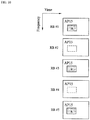
- the RE(s) mapped to the 1-port CSI-RS AP, of which the RB number is either even or odd, may be frequency-multiplexed.
- the RE mapped to the 1-port CSI-RS AP of each of the RBs of which the RB number is odd such as RB#1, #3, and #5 may be frequency-multiplexed.
- the RE of each of the RBs of which the RB number is even may be frequency-multiplexed.
- the BS 20 may transmit the CSI-RS configuration including frequency-multiplexing information indicating which REs are multiplexed via the RRC signaling (step S301). Then, the BS 20 may transmit the CSI-RS frequency-multiplexed to the UE 10 (step S302). The UE 10 may receive the 1-port CSI-RS with FDM in the unit of RB.
- the resource density for the CSI-RS transmission may decrease because the REs in the specific RB of which the RB number is either even or odd are frequency-multiplexed. This makes it possible to be the CSI-RS transmission efficiency can be improved.
- the RE mapping method (CSI-RS transmission with the low frequency resource density) using the frequency multiplexing scheme may be applied to not only the 1-port CSI-RS transmission but also the CSI-RS transmission other than the 1-port CSI-RS transmission.
- the RE mapping method using the frequency multiplexing scheme according to one or more embodiments of the third example of the present invention and the conventional RE mapping method may switched in the BS 20.
- the BS 20 may notify the UE 10 of information indicating a switch of the CSI-RS transmission with the low resource density and the CSI-RS transmission under the conventional LTE-A standard using the RRC signaling.
- a single CSI-RS resource defined in the conventional LTE-A standard may be assumed as multiple CSI-RS resources.
- the 8-port CSI-RS resource may be assumed as the four 2-port CSI-RS resources.
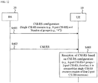
- the BS 20 may notify the UE 10 of the single CSI-RS resource (e.g., 8-port CSI-RS resource) and the number of groups (e.g., "4") via the RRC signaling (step S401).
- the number of groups is the number of the multiple CSI-RS resources constituting the single CSI-RS resource.
- the BS 20 may transmit the CSI-RS (step S402).
- the UE 10 may receive the CSI-RS based on the CSI-RS configuration including information indicating the single CSI-RS resource and the number of groups (step S403). For example, when the single CSI-RS resource is the 8-port CSI-RS resource and the number of groups is four, the UE 10 may assume the single CSI-RS resource consists of four 2-port CSI-RS resources. Thus, the multiple CSI-RS resources constituting the single CSI-RS resource may be reserved using the number of groups.
- the RE mapping method using the frequency multiplexing scheme according to one or more embodiments of the fourth example of the present invention and the conventional RE mapping method may switched in the BS 20.
- the BS 20 may notify the UE 10 of information indicating a switch of the CSI-RS transmission with the low resource density and the CSI-RS transmission under the conventional LTE-A standard using the RRC signaling.
- the multiple CSI-RS resources may be reserved based on information indicating the single CSI-RS resource and the number of APs for each of the groups.
- the 8-port CSI-RS resource may be assumed as the four 2-port CSI-RS resources.
- the BS 20 may notify the UE 10 of the single CSI-RS resource (e.g., 8-port CSI-RS resource) and the number of APs per group (e.g., "2") via the RRC signaling (step S401a). Then, the BS 20 may transmit the CSI-RS (step S402a).
- the UE 10 may receive the CSI-RS based on the CSI-RS configuration including information indicating the single CSI-RS resource and the number of APs per group (step S403a). For example, when the single CSI-RS resource is the 8-port CSI-RS resource and the number of APs per group is two, the UE 10 may assume the single CSI-RS resource consists of four 2-port CSI-RS resources. Thus, the multiple CSI-RS resources constituting the single CSI-RS resource may be reserved using the number of APs per group.
- Embodiments of a fifth example of the present invention will be described below in detail with reference to FIGs 14 and 15 .
- the LTE-A standard supports a zero-power (ZP) CSI-RS scheme for high accurate CSI estimation.
- ZP zero-power
- the conventional ZP CSI-RS may be notified using the REs mapped to the 4-port CSI-RS configurations. That is, the ZP CSI-RS resources can be designated only in a unit of four REs.
- PDSCH Physical Downlink Shared Channel
- the BS 20 may transmit, to the UE 10, information indicating a resource designated as a ZP CSI-RS (ZP RS) or an Interference Measurement Resource (IMR) dynamically.
- the UE 10 may receive the ZP RS or the IMR from the BS 10 using the information.
- the ZP CSI-RS resource may be designated in a unit of one RE.
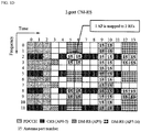
- the ZP CSI-RS resource in the unit of one RE may be notified based on a configuration of the REs mapped to the 1-port CSI-RS (low resource density like embodiments of the first example of the present invention). For example, as shown in FIG.
- the ZP CSI-RS resource in each RE may be notified as bitmaps (bit-map format) based on the configuration of the RE mapped to the 1-port CSI-RS.
- bitmaps bit-map format
- the number of REs available for 1-port CSI-RS transmission is 40.
- the BS 20 may notify the UE 10 of the ZP CSI-RS resource in each RE based on the configuration of the RE mapped to the 1-port CSI-RS via the higher layer signaling such as the RRC signaling and/or the lower layer signaling using Downlink Control Information (DCI) or Media Access Control (MAC) Control Element (CE) (step S501). Then, the BS 20 may transmit the CSI-RS (step S502). For example, the RE used for the ZP CSI-RS may be switched using the higher layer signaling such as the RRC signaling and/or the lower layer signaling using DCI format.
- DCI Downlink Control Information
- CE Media Access Control Element
- the ZP CIS-RS resource in a unit of two REs may be notified based on the REs mapped to the 2-port CSI-RS configurations. That is, ZP CSI-RS resource may be designated in a unit of two REs.
- the ZP CSI-RS resource may be indicated as a bit-map format.
- the ZP CSI-RS resource may be designated from 40 resources used in a 2-port CSI-RS mapping configuration where multiple CSI-RS resources are mapped to 2-antenna ports of the BS.
- a method for notifying the UE 10 of the conventional ZP CSI-RS resource (in a unit of four REs) and a method according to embodiments of the fifth example of the present invention may be switched using the higher layer signaling such as the RRC signaling and/or the lower layer signaling using DCI format.
- the ZP CSI-RS resource may be frequency-multiplexed.
- the RE "a" when the RE "a" is designated as the ZP CSI-RS (or the IMR), part of a plurality of RBs (RBs #1, #3, and #5) may be frequency-multiplexed.
- the RE "a" designated as the ZP CSI-RS may be the ZP CSI-RS resource.
- the RB number of the part of a plurality of RBs including the ZP CSI-RS resources may be either even or odd.
- the frequency-multiplexing information indicating the part of a plurality of RBs including the ZP CSI-RS resources may be notified from the BS to the UE via the RRC signaling.
- the ZP CSI-RS resource according to embodiments of the fifth example of the present invention may be used as an interference measurement resource (IMR).
- IMR interference measurement resource
- FIG. 16 is a diagram illustrating a schematic configuration of the BS 20 according to one or more embodiments of the present invention.
- the BS 20 may include a plurality of antennas 201, amplifier 202, transceiver (transmitter/receiver) 203, a baseband signal processor 204, a call processor 205 and a transmission path interface 206.
- User data that is transmitted on the DL from the BS 20 to the UE 20 is input from the core network 30, through the transmission path interface 206, into the baseband signal processor 204.
- signals are subjected to Packet Data Convergence Protocol (PDCP) layer processing, Radio Link Control (RLC) layer transmission processing such as division and coupling of user data and RLC retransmission control transmission processing, Medium Access Control (MAC) retransmission control, including, for example, HARQ transmission processing, scheduling, transport format selection, channel coding, inverse fast Fourier transform (IFFT) processing, and precoding processing.
- PDCP Packet Data Convergence Protocol
- RLC Radio Link Control
- MAC Medium Access Control
- HARQ transmission processing scheduling, transport format selection, channel coding, inverse fast Fourier transform (IFFT) processing, and precoding processing.
- the baseband signal processor 204 notifies each UE 10 of control information (system information) for communication in the cell by higher layer signaling (e.g., RRC signaling and broadcast channel).
- Information for communication in the cell includes, for example, UL or DL system bandwidth.
- each transceiver 203 baseband signals that are precoded per antenna and output from the baseband signal processor 204 are subjected to frequency conversion processing into a radio frequency band.
- the amplifier 202 amplifies the radio frequency signals having been subjected to frequency conversion, and the resultant signals are transmitted from the antennas 201.
- radio frequency signals are received in each antennas 201, amplified in the amplifier 202, subjected to frequency conversion and converted into baseband signals in the transceiver 203, and are input to the baseband signal processor 204.
- the baseband signal processor 204 performs FFT processing, IDFT processing, error correction decoding, MAC retransmission control reception processing, and RLC layer and PDCP layer reception processing on the user data included in the received baseband signals. Then, the resultant signals are transferred to the core network 30 through the transmission path interface 206.
- the call processor 205 performs call processing such as setting up and releasing a communication channel, manages the state of the BS 20, and manages the radio resources.
- FIG. 17 is a schematic configuration of the UE 10 according to one or more embodiments of the present invention.
- the UE 10 has a plurality of UE antennas 101, amplifiers 102, the circuit 103 comprising transceiver (transmitter/receiver) 1031, the controller 104, and an application 105.
- transceiver transmitter/receiver
- radio frequency signals received in the UE antennas 101 are amplified in the respective amplifiers 102, and subjected to frequency conversion into baseband signals in the transceiver 1031. These baseband signals are subjected to reception processing such as FFT processing, error correction decoding and retransmission control and so on, in the controller 104.
- the DL user data is transferred to the application 105.
- the application 105 performs processing related to higher layers above the physical layer and the MAC layer.
- broadcast information is also transferred to the application 105.
- UL user data is input from the application 105 to the controller 104.
- controller 104 retransmission control (Hybrid ARQ) transmission processing, channel coding, precoding, DFT processing, IFFT processing and so on are performed, and the resultant signals are transferred to each transceiver 1031.
- the transceiver 1031 the baseband signals output from the controller 104 are converted into a radio frequency band. After that, the frequency-converted radio frequency signals are amplified in the amplifier 102, and then, transmitted from the antenna 101.
- One or more embodiments of the present invention may be used for each of the uplink and the downlink independently.
- One or more embodiments of the present invention may be also used for both of the uplink and the downlink in common..
- the present disclosure mainly described examples of a channel and signaling scheme based on LTE/LTE-A, the present invention is not limited thereto.
- One or more embodiments of the present invention may apply to another channel and signaling scheme having the same functions as LTE/LTE-A, New Radio (NR), and a newly defined channel and signaling scheme.
- LTE/LTE-A Long Term Evolution/LTE-A
- NR New Radio
- the present disclosure mainly described examples of channel estimation and CSI feedback scheme based on the CSI-RS, the present invention is not limited thereto.
- One or more embodiments of the present invention may apply to another synchronization signal, reference signal, and physical channel.
- the signaling according to one or more embodiments of the present invention may be the higher layer signaling such as the RRC signaling and/or the lower layer signaling such as the DCI. Furthermore, the signaling according to one or more embodiments of the present invention may use the MAC-CE.
- the present disclosure mainly described examples of the UE including planer antennas, the present invention is not limited thereto.
- One or more embodiments of the present invention may also apply to the UE including one dimensional antennas and predetermined three dimensional antennas.
- the resource block (RB) and a subcarrier in the present disclosure may be replaced with each other.
- a subframe and a symbol may be replaced with each other.
- beamforming may be applied to the CSI-RS or may not be applied.
Landscapes
- Engineering & Computer Science (AREA)
- Signal Processing (AREA)
- Computer Networks & Wireless Communication (AREA)
- Mobile Radio Communication Systems (AREA)
Claims (10)
- Procédé de communication sans fil comprenant :une transmission (S101), à partir d'une station de base, BS, à un équipement utilisateur, UE, d'informations indiquant une ressource désignée comme un signal de référence, RS, à puissance nulle, ZP, ou une ressource de mesure de brouillage, IMR, de manière dynamique ; etune réception (S102), avec l'UE, du ZP RS ou de l'IMR à partir de la BS en utilisant les informations, dans lequella ressource est désignée dans une unité d'un élément de ressources, RE,les informations indiquent la ressource comme un format bitmap, etla ressource est désignée parmi des ressources prédéterminées utilisées dans une configuration de mappage de RS d'informations d'état de canal, CSI, sur un port.
- Procédé de communication sans fil selon la revendication 1, dans lequel la transmission transmet les informations en utilisant au moins un d'informations de commande en liaison descendante, DCI, et d'un élément de commande, CE, de commande d'accès au support, MAC.
- Procédé de communication sans fil selon la revendication 2, dans lequel la transmission transmet les informations en utilisant une signalisation de commande de ressources radio, RRC.
- Procédé de communication sans fil selon la revendication 1,
dans lequel une partie d'une pluralité de blocs de ressources, RB, incluent les ressources, respectivement, et
dans lequel les ressources sont multiplexées en fréquence. - Procédé de communication sans fil selon la revendication 4, comprenant en outre :une notification, avec la BS, à l'UE d'informations de multiplexage en fréquence indiquant la partie de la pluralité de RB,dans lequel la réception reçoit le ZP RS ou l'IMR en utilisant les informations de multiplexage en fréquence.
- Procédé de communication sans fil selon la revendication 4, dans lequel un nombre de RB de la partie de la pluralité de RB est soit pair soit impair.
- Procédé de communication sans fil selon la revendication 4, dans lequel la notification notifie les informations de multiplexage en fréquence en utilisant une signalisation de RRC.
- Procédé de communication sans fil selon la revendication 1, dans lequel la ressource est désignée dans une unité de deux RE.
- Procédé de communication sans fil selon la revendication 8, dans lequel les informations indiquent la ressource comme un format bitmap.
- Procédé de communication sans fil selon la revendication 8, dans lequel la ressource est désignée parmi 40 ressources utilisées dans une configuration de mappage de CSI-RS sur 2 ports où de multiples ressources de CSI-RS sont mappées sur 2 ports d'antenne de la BS.
Applications Claiming Priority (2)
| Application Number | Priority Date | Filing Date | Title |
|---|---|---|---|
| US201662400984P | 2016-09-28 | 2016-09-28 | |
| PCT/US2017/054061 WO2018064361A1 (fr) | 2016-09-28 | 2017-09-28 | Procédé de communication sans fil pour transmettre une indication de ressource de signal de référence |
Publications (2)
| Publication Number | Publication Date |
|---|---|
| EP3520303A1 EP3520303A1 (fr) | 2019-08-07 |
| EP3520303B1 true EP3520303B1 (fr) | 2021-01-13 |
Family
ID=60084092
Family Applications (1)
| Application Number | Title | Priority Date | Filing Date |
|---|---|---|---|
| EP17784477.6A Active EP3520303B1 (fr) | 2016-09-28 | 2017-09-28 | Procédé de communication sans fil pour transmettre une indication de ressource de signal de référence |
Country Status (5)
| Country | Link |
|---|---|
| US (2) | US20200007287A1 (fr) |
| EP (1) | EP3520303B1 (fr) |
| JP (1) | JP7035032B2 (fr) |
| CN (1) | CN109983729B (fr) |
| WO (1) | WO2018064361A1 (fr) |
Families Citing this family (5)
| Publication number | Priority date | Publication date | Assignee | Title |
|---|---|---|---|---|
| WO2018098802A1 (fr) * | 2016-12-02 | 2018-06-07 | Qualcomm Incorporated | Transmission de signaux de référence d'informations d'état de canal dans une nouvelle radio |
| WO2018144920A1 (fr) * | 2017-02-03 | 2018-08-09 | Ntt Docomo, Inc. | Équipement utilisateur et procédé de communication sans fil |
| WO2020033798A1 (fr) * | 2018-08-10 | 2020-02-13 | Intel Corporation | Planification pour la nouvelle radio dans un spectre sans licence (nr-u) |
| CN111756504B (zh) | 2019-03-29 | 2021-12-17 | 华为技术有限公司 | 下行控制信息传输的方法、装置及系统 |
| WO2021162522A1 (fr) * | 2020-02-13 | 2021-08-19 | 엘지전자 주식회사 | Procédé et appareil d'émission et de réception d'informations d'état de canal dans un système de communication sans fil |
Family Cites Families (31)
| Publication number | Priority date | Publication date | Assignee | Title |
|---|---|---|---|---|
| KR101710204B1 (ko) * | 2009-07-28 | 2017-03-08 | 엘지전자 주식회사 | 다중 입출력 통신 시스템에서 채널측정을 위한 기준신호의 전송 방법 및 그 장치 |
| EP2534857B1 (fr) * | 2010-02-12 | 2019-05-22 | BlackBerry Limited | Signal de référence pour la mise en uvre coordonnée d'un réseau multipoint |
| RU2486687C2 (ru) * | 2010-02-17 | 2013-06-27 | ЗетТиИ (ЮЭсЭй) ИНК. | Способы и системы для csi-rs-передачи в системах по усовершенствованному стандарту lte |
| US9407409B2 (en) * | 2010-02-23 | 2016-08-02 | Qualcomm Incorporated | Channel state information reference signals |
| EP2489228B1 (fr) * | 2010-02-24 | 2017-04-05 | ZTE Corporation | Méthodes et systèmes d'attribution de ressources csi-rs dans des systèmes lte-advanced |
| US8654734B2 (en) * | 2010-06-01 | 2014-02-18 | Texas Instruments Incorporated | Multi-cell channel state information-reference symbol patterns for long term evolution extended cyclic prefix and code division multiplexing-time multiplexing |
| EP2603990B1 (fr) * | 2010-08-13 | 2019-10-02 | LG Electronics Inc. | Procédé et station de base pour transmettre un signal de liaison descendante et procédé et équipement pour recevoir un signal de liaison descendante |
| GB201107363D0 (en) * | 2011-05-03 | 2011-06-15 | Renesas Mobile Corp | Method and apparatus for configuring resource elements for the provision of channel state information reference signals |
| WO2013069345A1 (fr) * | 2011-11-07 | 2013-05-16 | 株式会社エヌ・ティ・ティ・ドコモ | Système de communication sans fil, station de base, équipement mobile et procédé de mesure de brouillage |
| CN103391124B (zh) * | 2012-05-10 | 2018-06-19 | 中兴通讯股份有限公司 | 信道状态信息的配置方法、反馈方法、基站和终端 |
| WO2013172654A1 (fr) * | 2012-05-15 | 2013-11-21 | 엘지전자 주식회사 | Procédé de réception de données de liaison descendante, procédé d'émission de données de liaison descendante vers un équipement utilisateur et station de base associée |
| CN104350693B (zh) * | 2012-05-17 | 2018-04-24 | 三星电子株式会社 | 蜂窝移动通信系统中用于协作通信的信道估计方法和装置 |
| WO2014014394A1 (fr) * | 2012-07-17 | 2014-01-23 | Telefonaktiebolaget L M Ericsson (Publ) | Nœud de réseau et procédé dans celui-ci pour planifier une transmission de données en liaison descendante à un ue, et ue et procédé dans celui-ci pour recevoir une transmission de données en liaison descendante |
| KR20140095994A (ko) * | 2013-01-25 | 2014-08-04 | 한국전자통신연구원 | 셀 디스커버리 방법 |
| US9173109B2 (en) * | 2013-03-15 | 2015-10-27 | Blackberry Limited | Radio link quality monitoring |
| CN104284355B (zh) * | 2013-07-11 | 2019-08-13 | 中兴通讯股份有限公司 | 一种干扰测量方法、系统及相关设备 |
| US9967809B2 (en) * | 2013-09-24 | 2018-05-08 | Zte Wistron Telecom Ab | Method and apparatus for modified reference signal transmission for cell discovery |
| JP6114153B2 (ja) * | 2013-09-26 | 2017-04-12 | 株式会社Nttドコモ | 基地局、移動局、参照信号送信方法及びチャネル品質測定方法 |
| CN105356978B (zh) * | 2014-08-21 | 2019-06-07 | 电信科学技术研究院 | 一种传输csi-rs的方法和设备 |
| US9743392B2 (en) * | 2015-01-30 | 2017-08-22 | Motorola Mobility Llc | Method and apparatus for signaling aperiodic channel state indication reference signals for LTE operation |
| WO2016182591A1 (fr) * | 2015-05-08 | 2016-11-17 | Intel Corporation | Brouillage et modulation de signaux de référence d'informations d'état de canal (csi-rs) pour systèmes à pleine dimension à entrées multiples-sorties multiples (fd-mimo) |
| EP3758250B1 (fr) * | 2015-05-14 | 2024-03-13 | Telefonaktiebolaget LM Ericsson (publ) | Configuration de signaux de référence de mesurage pour mimo |
| KR102486805B1 (ko) * | 2015-09-18 | 2023-01-11 | 삼성전자 주식회사 | 무선 통신 시스템에서 피드백 신호를 송수신하는 방법 및 장치 |
| CN106559199A (zh) * | 2015-09-25 | 2017-04-05 | 中兴通讯股份有限公司 | 一种配置信道状态测量导频的方法及装置 |
| CN106685620B (zh) * | 2015-11-06 | 2021-02-12 | 中兴通讯股份有限公司 | 信道状态测量导频的配置方法及装置、解析方法及装置 |
| WO2017136068A1 (fr) * | 2016-02-03 | 2017-08-10 | Intel Corporation | Réduction de surdébit csi (informations d'état de canal)-rs (signal de référence) pour systèmes fd (pleines dimensions)-mimo (entrées multiples - sorties multiples) |
| KR20170112945A (ko) * | 2016-04-01 | 2017-10-12 | 삼성전자주식회사 | 이동통신 시스템에서 기기 간 통신과 셀룰라 통신의 공존 방법 및 장치 |
| JP6987788B2 (ja) * | 2016-05-13 | 2022-01-05 | テレフオンアクチーボラゲット エルエム エリクソン(パブル) | 低減密度csi−rsのための機構 |
| CN107623542B (zh) * | 2016-07-13 | 2023-09-01 | 华为技术有限公司 | 一种发送参考信号的方法、相关设备及通信系统 |
| KR102414697B1 (ko) * | 2016-07-29 | 2022-06-29 | 삼성전자 주식회사 | 다수의 배열 안테나를 사용하는 이동통신 시스템에서 csi-rs 포트 공유를 위한 기준신호 설정 방법 및 장치 |
| US11368963B2 (en) * | 2016-09-21 | 2022-06-21 | Apple Inc. | Reduced CSI (channel state information)-RS (reference signal) density support for FD (full dimensional)-MIMO (multiple input multiple output) systems |
-
2017
- 2017-09-28 EP EP17784477.6A patent/EP3520303B1/fr active Active
- 2017-09-28 CN CN201780071971.7A patent/CN109983729B/zh active Active
- 2017-09-28 WO PCT/US2017/054061 patent/WO2018064361A1/fr not_active Ceased
- 2017-09-28 US US16/337,799 patent/US20200007287A1/en not_active Abandoned
- 2017-09-28 JP JP2019517093A patent/JP7035032B2/ja active Active
-
2021
- 2021-05-21 US US17/326,402 patent/US20210273762A1/en active Pending
Non-Patent Citations (1)
| Title |
|---|
| None * |
Also Published As
| Publication number | Publication date |
|---|---|
| US20210273762A1 (en) | 2021-09-02 |
| CN109983729B (zh) | 2021-12-28 |
| US20200007287A1 (en) | 2020-01-02 |
| JP7035032B2 (ja) | 2022-03-14 |
| WO2018064361A1 (fr) | 2018-04-05 |
| JP2020503708A (ja) | 2020-01-30 |
| CN109983729A (zh) | 2019-07-05 |
| EP3520303A1 (fr) | 2019-08-07 |
Similar Documents
| Publication | Publication Date | Title |
|---|---|---|
| EP3497805B1 (fr) | Procédé de transmission de liaison montante | |
| EP3412068B1 (fr) | Canaux communs de formation de faisceau dans la nouvelle radiocommunication 5g | |
| US11064480B2 (en) | User terminal, radio base station and radio communication method | |
| EP4030675B1 (fr) | Procédé d'attribution de ressources de fréquence | |
| US11456839B2 (en) | User equipment and wireless communication method | |
| US20210273762A1 (en) | Wireless communication method, user equipment, base station, and system | |
| US11121837B2 (en) | User equipment and method of SRS transmission | |
| US20190253211A1 (en) | Wireless communication method | |
| JP2020507988A5 (fr) | ||
| EP3334210B1 (fr) | Terminal utilisateur, station de base sans fil et procédé de communication sans fil | |
| US20190098638A1 (en) | Method for wireless communication, user equipment, and base station | |
| US12176983B2 (en) | Method of transmitting channel state information-reference signal (CSI-RS), base station, and user equipment | |
| US11677521B2 (en) | User terminal, radio base station and radio communication method | |
| US20200169365A1 (en) | Transmission and reception point (trp) and method of channel state information-reference signal (csi-rs) transmission | |
| EP3577837B1 (fr) | Équipement utilisateur et procédé de communication sans fil |
Legal Events
| Date | Code | Title | Description |
|---|---|---|---|
| STAA | Information on the status of an ep patent application or granted ep patent |
Free format text: STATUS: UNKNOWN |
|
| STAA | Information on the status of an ep patent application or granted ep patent |
Free format text: STATUS: THE INTERNATIONAL PUBLICATION HAS BEEN MADE |
|
| PUAI | Public reference made under article 153(3) epc to a published international application that has entered the european phase |
Free format text: ORIGINAL CODE: 0009012 |
|
| STAA | Information on the status of an ep patent application or granted ep patent |
Free format text: STATUS: REQUEST FOR EXAMINATION WAS MADE |
|
| 17P | Request for examination filed |
Effective date: 20190417 |
|
| AK | Designated contracting states |
Kind code of ref document: A1 Designated state(s): AL AT BE BG CH CY CZ DE DK EE ES FI FR GB GR HR HU IE IS IT LI LT LU LV MC MK MT NL NO PL PT RO RS SE SI SK SM TR |
|
| AX | Request for extension of the european patent |
Extension state: BA ME |
|
| DAV | Request for validation of the european patent (deleted) | ||
| DAX | Request for extension of the european patent (deleted) | ||
| GRAP | Despatch of communication of intention to grant a patent |
Free format text: ORIGINAL CODE: EPIDOSNIGR1 |
|
| STAA | Information on the status of an ep patent application or granted ep patent |
Free format text: STATUS: GRANT OF PATENT IS INTENDED |
|
| INTG | Intention to grant announced |
Effective date: 20200918 |
|
| GRAS | Grant fee paid |
Free format text: ORIGINAL CODE: EPIDOSNIGR3 |
|
| GRAA | (expected) grant |
Free format text: ORIGINAL CODE: 0009210 |
|
| STAA | Information on the status of an ep patent application or granted ep patent |
Free format text: STATUS: THE PATENT HAS BEEN GRANTED |
|
| AK | Designated contracting states |
Kind code of ref document: B1 Designated state(s): AL AT BE BG CH CY CZ DE DK EE ES FI FR GB GR HR HU IE IS IT LI LT LU LV MC MK MT NL NO PL PT RO RS SE SI SK SM TR |
|
| REG | Reference to a national code |
Ref country code: GB Ref legal event code: FG4D |
|
| REG | Reference to a national code |
Ref country code: CH Ref legal event code: EP |
|
| REG | Reference to a national code |
Ref country code: DE Ref legal event code: R096 Ref document number: 602017031436 Country of ref document: DE |
|
| REG | Reference to a national code |
Ref country code: IE Ref legal event code: FG4D |
|
| REG | Reference to a national code |
Ref country code: AT Ref legal event code: REF Ref document number: 1355339 Country of ref document: AT Kind code of ref document: T Effective date: 20210215 |
|
| REG | Reference to a national code |
Ref country code: AT Ref legal event code: MK05 Ref document number: 1355339 Country of ref document: AT Kind code of ref document: T Effective date: 20210113 |
|
| REG | Reference to a national code |
Ref country code: NL Ref legal event code: MP Effective date: 20210113 |
|
| REG | Reference to a national code |
Ref country code: LT Ref legal event code: MG9D |
|
| PG25 | Lapsed in a contracting state [announced via postgrant information from national office to epo] |
Ref country code: HR Free format text: LAPSE BECAUSE OF FAILURE TO SUBMIT A TRANSLATION OF THE DESCRIPTION OR TO PAY THE FEE WITHIN THE PRESCRIBED TIME-LIMIT Effective date: 20210113 Ref country code: GR Free format text: LAPSE BECAUSE OF FAILURE TO SUBMIT A TRANSLATION OF THE DESCRIPTION OR TO PAY THE FEE WITHIN THE PRESCRIBED TIME-LIMIT Effective date: 20210414 Ref country code: FI Free format text: LAPSE BECAUSE OF FAILURE TO SUBMIT A TRANSLATION OF THE DESCRIPTION OR TO PAY THE FEE WITHIN THE PRESCRIBED TIME-LIMIT Effective date: 20210113 Ref country code: PT Free format text: LAPSE BECAUSE OF FAILURE TO SUBMIT A TRANSLATION OF THE DESCRIPTION OR TO PAY THE FEE WITHIN THE PRESCRIBED TIME-LIMIT Effective date: 20210513 Ref country code: NO Free format text: LAPSE BECAUSE OF FAILURE TO SUBMIT A TRANSLATION OF THE DESCRIPTION OR TO PAY THE FEE WITHIN THE PRESCRIBED TIME-LIMIT Effective date: 20210413 Ref country code: BG Free format text: LAPSE BECAUSE OF FAILURE TO SUBMIT A TRANSLATION OF THE DESCRIPTION OR TO PAY THE FEE WITHIN THE PRESCRIBED TIME-LIMIT Effective date: 20210413 Ref country code: LT Free format text: LAPSE BECAUSE OF FAILURE TO SUBMIT A TRANSLATION OF THE DESCRIPTION OR TO PAY THE FEE WITHIN THE PRESCRIBED TIME-LIMIT Effective date: 20210113 |
|
| PG25 | Lapsed in a contracting state [announced via postgrant information from national office to epo] |
Ref country code: SE Free format text: LAPSE BECAUSE OF FAILURE TO SUBMIT A TRANSLATION OF THE DESCRIPTION OR TO PAY THE FEE WITHIN THE PRESCRIBED TIME-LIMIT Effective date: 20210113 Ref country code: PL Free format text: LAPSE BECAUSE OF FAILURE TO SUBMIT A TRANSLATION OF THE DESCRIPTION OR TO PAY THE FEE WITHIN THE PRESCRIBED TIME-LIMIT Effective date: 20210113 Ref country code: RS Free format text: LAPSE BECAUSE OF FAILURE TO SUBMIT A TRANSLATION OF THE DESCRIPTION OR TO PAY THE FEE WITHIN THE PRESCRIBED TIME-LIMIT Effective date: 20210113 Ref country code: LV Free format text: LAPSE BECAUSE OF FAILURE TO SUBMIT A TRANSLATION OF THE DESCRIPTION OR TO PAY THE FEE WITHIN THE PRESCRIBED TIME-LIMIT Effective date: 20210113 Ref country code: AT Free format text: LAPSE BECAUSE OF FAILURE TO SUBMIT A TRANSLATION OF THE DESCRIPTION OR TO PAY THE FEE WITHIN THE PRESCRIBED TIME-LIMIT Effective date: 20210113 |
|
| PG25 | Lapsed in a contracting state [announced via postgrant information from national office to epo] |
Ref country code: IS Free format text: LAPSE BECAUSE OF FAILURE TO SUBMIT A TRANSLATION OF THE DESCRIPTION OR TO PAY THE FEE WITHIN THE PRESCRIBED TIME-LIMIT Effective date: 20210513 |
|
| REG | Reference to a national code |
Ref country code: DE Ref legal event code: R097 Ref document number: 602017031436 Country of ref document: DE |
|
| PG25 | Lapsed in a contracting state [announced via postgrant information from national office to epo] |
Ref country code: SM Free format text: LAPSE BECAUSE OF FAILURE TO SUBMIT A TRANSLATION OF THE DESCRIPTION OR TO PAY THE FEE WITHIN THE PRESCRIBED TIME-LIMIT Effective date: 20210113 Ref country code: EE Free format text: LAPSE BECAUSE OF FAILURE TO SUBMIT A TRANSLATION OF THE DESCRIPTION OR TO PAY THE FEE WITHIN THE PRESCRIBED TIME-LIMIT Effective date: 20210113 Ref country code: CZ Free format text: LAPSE BECAUSE OF FAILURE TO SUBMIT A TRANSLATION OF THE DESCRIPTION OR TO PAY THE FEE WITHIN THE PRESCRIBED TIME-LIMIT Effective date: 20210113 |
|
| PLBE | No opposition filed within time limit |
Free format text: ORIGINAL CODE: 0009261 |
|
| STAA | Information on the status of an ep patent application or granted ep patent |
Free format text: STATUS: NO OPPOSITION FILED WITHIN TIME LIMIT |
|
| PG25 | Lapsed in a contracting state [announced via postgrant information from national office to epo] |
Ref country code: SK Free format text: LAPSE BECAUSE OF FAILURE TO SUBMIT A TRANSLATION OF THE DESCRIPTION OR TO PAY THE FEE WITHIN THE PRESCRIBED TIME-LIMIT Effective date: 20210113 Ref country code: DK Free format text: LAPSE BECAUSE OF FAILURE TO SUBMIT A TRANSLATION OF THE DESCRIPTION OR TO PAY THE FEE WITHIN THE PRESCRIBED TIME-LIMIT Effective date: 20210113 Ref country code: RO Free format text: LAPSE BECAUSE OF FAILURE TO SUBMIT A TRANSLATION OF THE DESCRIPTION OR TO PAY THE FEE WITHIN THE PRESCRIBED TIME-LIMIT Effective date: 20210113 |
|
| 26N | No opposition filed |
Effective date: 20211014 |
|
| PG25 | Lapsed in a contracting state [announced via postgrant information from national office to epo] |
Ref country code: ES Free format text: LAPSE BECAUSE OF FAILURE TO SUBMIT A TRANSLATION OF THE DESCRIPTION OR TO PAY THE FEE WITHIN THE PRESCRIBED TIME-LIMIT Effective date: 20210113 Ref country code: AL Free format text: LAPSE BECAUSE OF FAILURE TO SUBMIT A TRANSLATION OF THE DESCRIPTION OR TO PAY THE FEE WITHIN THE PRESCRIBED TIME-LIMIT Effective date: 20210113 |
|
| PG25 | Lapsed in a contracting state [announced via postgrant information from national office to epo] |
Ref country code: SI Free format text: LAPSE BECAUSE OF FAILURE TO SUBMIT A TRANSLATION OF THE DESCRIPTION OR TO PAY THE FEE WITHIN THE PRESCRIBED TIME-LIMIT Effective date: 20210113 |
|
| REG | Reference to a national code |
Ref country code: DE Ref legal event code: R081 Ref document number: 602017031436 Country of ref document: DE Owner name: NTT DOCOMO, INC., JP Free format text: FORMER OWNERS: DOCOMO INNOVATIONS, INC., PALO ALTO, CA, US; NTT DOCOMO, INC., TOKYO, JP |
|
| PG25 | Lapsed in a contracting state [announced via postgrant information from national office to epo] |
Ref country code: IT Free format text: LAPSE BECAUSE OF FAILURE TO SUBMIT A TRANSLATION OF THE DESCRIPTION OR TO PAY THE FEE WITHIN THE PRESCRIBED TIME-LIMIT Effective date: 20210113 |
|
| REG | Reference to a national code |
Ref country code: CH Ref legal event code: PL |
|
| REG | Reference to a national code |
Ref country code: BE Ref legal event code: MM Effective date: 20210930 |
|
| GBPC | Gb: european patent ceased through non-payment of renewal fee |
Effective date: 20210928 |
|
| PG25 | Lapsed in a contracting state [announced via postgrant information from national office to epo] |
Ref country code: IS Free format text: LAPSE BECAUSE OF FAILURE TO SUBMIT A TRANSLATION OF THE DESCRIPTION OR TO PAY THE FEE WITHIN THE PRESCRIBED TIME-LIMIT Effective date: 20210513 Ref country code: MC Free format text: LAPSE BECAUSE OF FAILURE TO SUBMIT A TRANSLATION OF THE DESCRIPTION OR TO PAY THE FEE WITHIN THE PRESCRIBED TIME-LIMIT Effective date: 20210113 |
|
| PG25 | Lapsed in a contracting state [announced via postgrant information from national office to epo] |
Ref country code: LU Free format text: LAPSE BECAUSE OF NON-PAYMENT OF DUE FEES Effective date: 20210928 Ref country code: IE Free format text: LAPSE BECAUSE OF NON-PAYMENT OF DUE FEES Effective date: 20210928 Ref country code: GB Free format text: LAPSE BECAUSE OF NON-PAYMENT OF DUE FEES Effective date: 20210928 Ref country code: FR Free format text: LAPSE BECAUSE OF NON-PAYMENT OF DUE FEES Effective date: 20210930 Ref country code: BE Free format text: LAPSE BECAUSE OF NON-PAYMENT OF DUE FEES Effective date: 20210930 |
|
| PG25 | Lapsed in a contracting state [announced via postgrant information from national office to epo] |
Ref country code: LI Free format text: LAPSE BECAUSE OF NON-PAYMENT OF DUE FEES Effective date: 20210930 Ref country code: CH Free format text: LAPSE BECAUSE OF NON-PAYMENT OF DUE FEES Effective date: 20210930 |
|
| P01 | Opt-out of the competence of the unified patent court (upc) registered |
Effective date: 20230509 |
|
| PG25 | Lapsed in a contracting state [announced via postgrant information from national office to epo] |
Ref country code: NL Free format text: LAPSE BECAUSE OF NON-PAYMENT OF DUE FEES Effective date: 20210113 Ref country code: CY Free format text: LAPSE BECAUSE OF FAILURE TO SUBMIT A TRANSLATION OF THE DESCRIPTION OR TO PAY THE FEE WITHIN THE PRESCRIBED TIME-LIMIT Effective date: 20210113 |
|
| PG25 | Lapsed in a contracting state [announced via postgrant information from national office to epo] |
Ref country code: HU Free format text: LAPSE BECAUSE OF FAILURE TO SUBMIT A TRANSLATION OF THE DESCRIPTION OR TO PAY THE FEE WITHIN THE PRESCRIBED TIME-LIMIT; INVALID AB INITIO Effective date: 20170928 |
|
| PG25 | Lapsed in a contracting state [announced via postgrant information from national office to epo] |
Ref country code: MK Free format text: LAPSE BECAUSE OF FAILURE TO SUBMIT A TRANSLATION OF THE DESCRIPTION OR TO PAY THE FEE WITHIN THE PRESCRIBED TIME-LIMIT Effective date: 20210113 |
|
| PG25 | Lapsed in a contracting state [announced via postgrant information from national office to epo] |
Ref country code: TR Free format text: LAPSE BECAUSE OF FAILURE TO SUBMIT A TRANSLATION OF THE DESCRIPTION OR TO PAY THE FEE WITHIN THE PRESCRIBED TIME-LIMIT Effective date: 20210113 |
|
| PG25 | Lapsed in a contracting state [announced via postgrant information from national office to epo] |
Ref country code: MT Free format text: LAPSE BECAUSE OF FAILURE TO SUBMIT A TRANSLATION OF THE DESCRIPTION OR TO PAY THE FEE WITHIN THE PRESCRIBED TIME-LIMIT Effective date: 20210113 |
|
| PGFP | Annual fee paid to national office [announced via postgrant information from national office to epo] |
Ref country code: DE Payment date: 20250919 Year of fee payment: 9 |