EP3520332B1 - Formation de faisceaux hybrides analogiques/numériques - Google Patents
Formation de faisceaux hybrides analogiques/numériques Download PDFInfo
- Publication number
- EP3520332B1 EP3520332B1 EP17857497.6A EP17857497A EP3520332B1 EP 3520332 B1 EP3520332 B1 EP 3520332B1 EP 17857497 A EP17857497 A EP 17857497A EP 3520332 B1 EP3520332 B1 EP 3520332B1
- Authority
- EP
- European Patent Office
- Prior art keywords
- beams
- cluster
- analog
- hybrid
- digital
- Prior art date
- Legal status (The legal status is an assumption and is not a legal conclusion. Google has not performed a legal analysis and makes no representation as to the accuracy of the status listed.)
- Active
Links
Images


Classifications
-
- H—ELECTRICITY
- H04—ELECTRIC COMMUNICATION TECHNIQUE
- H04B—TRANSMISSION
- H04B7/00—Radio transmission systems, i.e. using radiation field
- H04B7/02—Diversity systems; Multi-antenna system, i.e. transmission or reception using multiple antennas
- H04B7/04—Diversity systems; Multi-antenna system, i.e. transmission or reception using multiple antennas using two or more spaced independent antennas
- H04B7/06—Diversity systems; Multi-antenna system, i.e. transmission or reception using multiple antennas using two or more spaced independent antennas at the transmitting station
- H04B7/0613—Diversity systems; Multi-antenna system, i.e. transmission or reception using multiple antennas using two or more spaced independent antennas at the transmitting station using simultaneous transmission
- H04B7/0615—Diversity systems; Multi-antenna system, i.e. transmission or reception using multiple antennas using two or more spaced independent antennas at the transmitting station using simultaneous transmission of weighted versions of same signal
- H04B7/0617—Diversity systems; Multi-antenna system, i.e. transmission or reception using multiple antennas using two or more spaced independent antennas at the transmitting station using simultaneous transmission of weighted versions of same signal for beam forming
-
- H—ELECTRICITY
- H01—ELECTRIC ELEMENTS
- H01Q—ANTENNAS, i.e. RADIO AERIALS
- H01Q3/00—Arrangements for changing or varying the orientation or the shape of the directional pattern of the waves radiated from an antenna or antenna system
- H01Q3/26—Arrangements for changing or varying the orientation or the shape of the directional pattern of the waves radiated from an antenna or antenna system varying the relative phase or relative amplitude of energisation between two or more active radiating elements; varying the distribution of energy across a radiating aperture
- H01Q3/2682—Time delay steered arrays
-
- H—ELECTRICITY
- H01—ELECTRIC ELEMENTS
- H01Q—ANTENNAS, i.e. RADIO AERIALS
- H01Q3/00—Arrangements for changing or varying the orientation or the shape of the directional pattern of the waves radiated from an antenna or antenna system
- H01Q3/26—Arrangements for changing or varying the orientation or the shape of the directional pattern of the waves radiated from an antenna or antenna system varying the relative phase or relative amplitude of energisation between two or more active radiating elements; varying the distribution of energy across a radiating aperture
- H01Q3/28—Arrangements for changing or varying the orientation or the shape of the directional pattern of the waves radiated from an antenna or antenna system varying the relative phase or relative amplitude of energisation between two or more active radiating elements; varying the distribution of energy across a radiating aperture varying the amplitude
-
- H—ELECTRICITY
- H01—ELECTRIC ELEMENTS
- H01Q—ANTENNAS, i.e. RADIO AERIALS
- H01Q3/00—Arrangements for changing or varying the orientation or the shape of the directional pattern of the waves radiated from an antenna or antenna system
- H01Q3/26—Arrangements for changing or varying the orientation or the shape of the directional pattern of the waves radiated from an antenna or antenna system varying the relative phase or relative amplitude of energisation between two or more active radiating elements; varying the distribution of energy across a radiating aperture
- H01Q3/30—Arrangements for changing or varying the orientation or the shape of the directional pattern of the waves radiated from an antenna or antenna system varying the relative phase or relative amplitude of energisation between two or more active radiating elements; varying the distribution of energy across a radiating aperture varying the relative phase between the radiating elements of an array
- H01Q3/34—Arrangements for changing or varying the orientation or the shape of the directional pattern of the waves radiated from an antenna or antenna system varying the relative phase or relative amplitude of energisation between two or more active radiating elements; varying the distribution of energy across a radiating aperture varying the relative phase between the radiating elements of an array by electrical means
- H01Q3/36—Arrangements for changing or varying the orientation or the shape of the directional pattern of the waves radiated from an antenna or antenna system varying the relative phase or relative amplitude of energisation between two or more active radiating elements; varying the distribution of energy across a radiating aperture varying the relative phase between the radiating elements of an array by electrical means with variable phase-shifters
-
- H—ELECTRICITY
- H04—ELECTRIC COMMUNICATION TECHNIQUE
- H04B—TRANSMISSION
- H04B7/00—Radio transmission systems, i.e. using radiation field
- H04B7/02—Diversity systems; Multi-antenna system, i.e. transmission or reception using multiple antennas
- H04B7/04—Diversity systems; Multi-antenna system, i.e. transmission or reception using multiple antennas using two or more spaced independent antennas
- H04B7/06—Diversity systems; Multi-antenna system, i.e. transmission or reception using multiple antennas using two or more spaced independent antennas at the transmitting station
- H04B7/0613—Diversity systems; Multi-antenna system, i.e. transmission or reception using multiple antennas using two or more spaced independent antennas at the transmitting station using simultaneous transmission
- H04B7/068—Diversity systems; Multi-antenna system, i.e. transmission or reception using multiple antennas using two or more spaced independent antennas at the transmitting station using simultaneous transmission using space frequency diversity
-
- H—ELECTRICITY
- H04—ELECTRIC COMMUNICATION TECHNIQUE
- H04B—TRANSMISSION
- H04B7/00—Radio transmission systems, i.e. using radiation field
- H04B7/02—Diversity systems; Multi-antenna system, i.e. transmission or reception using multiple antennas
- H04B7/04—Diversity systems; Multi-antenna system, i.e. transmission or reception using multiple antennas using two or more spaced independent antennas
- H04B7/06—Diversity systems; Multi-antenna system, i.e. transmission or reception using multiple antennas using two or more spaced independent antennas at the transmitting station
- H04B7/0686—Hybrid systems, i.e. switching and simultaneous transmission
- H04B7/0691—Hybrid systems, i.e. switching and simultaneous transmission using subgroups of transmit antennas
-
- H—ELECTRICITY
- H04—ELECTRIC COMMUNICATION TECHNIQUE
- H04B—TRANSMISSION
- H04B7/00—Radio transmission systems, i.e. using radiation field
- H04B7/14—Relay systems
- H04B7/15—Active relay systems
- H04B7/185—Space-based or airborne stations; Stations for satellite systems
- H04B7/1851—Systems using a satellite or space-based relay
- H04B7/18513—Transmission in a satellite or space-based system
-
- H—ELECTRICITY
- H04—ELECTRIC COMMUNICATION TECHNIQUE
- H04B—TRANSMISSION
- H04B7/00—Radio transmission systems, i.e. using radiation field
- H04B7/14—Relay systems
- H04B7/15—Active relay systems
- H04B7/185—Space-based or airborne stations; Stations for satellite systems
- H04B7/1851—Systems using a satellite or space-based relay
- H04B7/18515—Transmission equipment in satellites or space-based relays
-
- H—ELECTRICITY
- H04—ELECTRIC COMMUNICATION TECHNIQUE
- H04B—TRANSMISSION
- H04B7/00—Radio transmission systems, i.e. using radiation field
- H04B7/14—Relay systems
- H04B7/15—Active relay systems
- H04B7/204—Multiple access
- H04B7/2041—Spot beam multiple access
-
- H—ELECTRICITY
- H04—ELECTRIC COMMUNICATION TECHNIQUE
- H04W—WIRELESS COMMUNICATION NETWORKS
- H04W16/00—Network planning, e.g. coverage or traffic planning tools; Network deployment, e.g. resource partitioning or cells structures
- H04W16/24—Cell structures
- H04W16/28—Cell structures using beam steering
-
- H—ELECTRICITY
- H01—ELECTRIC ELEMENTS
- H01Q—ANTENNAS, i.e. RADIO AERIALS
- H01Q21/00—Antenna arrays or systems
- H01Q21/0006—Particular feeding systems
-
- H—ELECTRICITY
- H01—ELECTRIC ELEMENTS
- H01Q—ANTENNAS, i.e. RADIO AERIALS
- H01Q3/00—Arrangements for changing or varying the orientation or the shape of the directional pattern of the waves radiated from an antenna or antenna system
- H01Q3/02—Arrangements for changing or varying the orientation or the shape of the directional pattern of the waves radiated from an antenna or antenna system using mechanical movement of antenna or antenna system as a whole
Definitions
- the following disclosure relates generally to a hybrid analog/digital beamforming communications system.
- Some communications systems e.g., a satellite communications system, provide multiple communication beams that connect diverse terrestrial regions.
- a target area is covered using analog communications beams.
- a target area is covered using digital communications beams.
- US 2016/261325 Al relates to a base station for transmitting a signal in a wireless communication system supporting multi user-multiple input and multiple output (MU-MIMO).
- MU-MIMO multi user-multiple input and multiple output
- the base station comprises: a radio frequency unit (RF); and a processor, wherein the processor can be configured to generate beams for subgroups including a plurality of terminals using analog beamforming, compensate beam phase difference which occurs between beams of subgroups using digital beamforming, after analog beamforming, and transmit, to the terminals, signals generated based on analog beamforming and digital beamforming.
- RF radio frequency unit
- US 2015/111584 A1 relates to a system for overlapping cells for wireless coverage in a cellular communication system.
- the system includes a beam-weight generator and beamformer coupled to the beam-weight generator.
- the beam-weight generator is configured to generate a plurality of beam weights including at least first and second sets of beam weights, and the beamformer is configured to apply the first and second sets of beam weights to signals in a cellular communication system.
- the cellular communication system provides coverage over a geographic region divided into cells arranged in overlapping first and second layers of cells having criteria optimized for respective, distinct first and second types of services, or communication by respective, distinct first and second types of user terminals. In this regard, the criteria are reflected in the first and second sets of beam weights.
- US 5 220 320 A describes a "modified rearrangeable" switch matrix combining both ⁇ switching elements and crossbar switch matrices in a single switch configuration, with ⁇ switching elements used at the input and output and at least one crossbar switch matrix in the middle to receive its inputs from ⁇ switching elements and provide its outputs to ⁇ switching elements.
- the following disclosure describes a communications system for hybrid analog/digital beamforming to generate a set of communication beams (also referred to as "beams") to cover a target area.
- the system includes a beamforming apparatus for generating hybrid analog/digital beams, where beamforming refers to techniques to form beams to establish communications channels.
- the beamforming apparatus is a spacecraft, e.g., a satellite, a drone, an airplane, or an aerial platform.
- the following sections describe the hybrid analog/digital beamforming in the context of a satellite.
- the techniques are also applicable to other beamforming apparatus, e.g., other forms of space-based beamforming devices.
- a satellite that performs hybrid analog/digital beamforming includes multiple antenna radiating elements (also known as “feeds") and associated phase shifters for forming analog beams.
- the satellite includes processing circuitry, comprising one or more beamformer processors, that control the feeds to form the analog beams.
- the feeds are divided into groups among hardware structures called "panels," also referred to as analog beamformers.
- the processing circuitry controls the panels to form one or more analog beams per panel, with the analog beams from some or all the panels providing coverage in a region in the target area, generating a cluster.
- the beamformer processors in the processing circuitry also form digital beams using digital beamforming coefficients stored in tables.
- the processing circuitry forms one or more digital beams in the cluster by phase and gain combining the analog beams in the cluster, according to appended claim 1.
- the hybrid analog/digital beams e.g., digital beams that are generated by combining the analog beams in a cluster, are also referred to as hybrid beams.
- Hybrid beams are accordingly digital beams that are generated in a hierarchical manner - first by forming analog beams, and then by combining the analog beams to form the digital beams that correspond to the hybrid beams.
- pure digital beams are formed by directly combining the phase, delay, or amplitude (or gain) of the feeds using digital coefficients-there is no intermediate formation of analog beams. Pure digital beams can be created in any region.
- the digital beamformers in the spacecraft are constrained to create the hybrid beams, i.e., the digital beams, within the coverage areas of the underlying analog beams.
- the analog beamformers combine the analog beams to provide the contours of the coverage areas in which the digital beams are generated.
- the satellite in the communications system divides a target coverage area into multiple regions.
- the processing circuitry in the satellite provides, in a region, analog beams formed by one or more panels to create a cluster, and generates one or more digital beams for the cluster by combining the corresponding analog beams, as noted above.
- the footprints of the analog beams overlap to some degree, e.g., either partially or completely.
- digital beams are formed by combining the overlapping analog beams.
- the footprints of at least some of the analog beams are non-overlapping. In such cases, at least some digital beams are formed by combining separate groups of the analog beams, which can include overlapping analog beams.
- the processing circuitry After forming the hybrid beams in a region, the processing circuitry repeats the process in a neighboring region, until all the regions are addressed, thereby covering the target area with the hybrid beams.
- the processing circuitry arranges the hybrid beams in a cluster in rows and columns. In some implementations, the processing circuitry horizontally shifts some rows, or vertically shift some columns, or both, to conform to the boundaries of the cluster. Additionally or alternatively, the processing circuitry stretches or contracts hybrid beams in some rows, or some columns, or both, to conform to the boundaries of the cluster.
- the processing circuitry horizontally shifts some rows, or vertically shift some columns, or both, in a cluster such that the rows and columns of hybrid beams in the cluster are adjacent to the rows and columns of hybrid beams in a neighboring cluster, for no gap in coverage.
- the invention defines an apparatus according to appended claim 1.
- the apparatus may include one or more phase shifters for each feed, wherein a number of analog beams generated by a panel corresponds to a number of phase shifters associated with each feed included in the panel.
- the plurality of analog beams generated for a region may overlap at least partially with each other in the region.
- the processing circuitry may generate the plurality of analog beams for a region such that a number of analog beams to fully cover the region.
- a shape of the cluster may be customizable to fully cover the region.
- the apparatus may include machine-readable media that store digital beamforming coefficients for the digital beams.
- One or more hybrid beams in a cluster may be generated using the digital beamforming coefficients for the digital beams.
- the processing circuitry may generate the one or more hybrid beams in a cluster by determining a digital beam width such that edge of coverage reduction is within a preselected threshold of power at the center of the digital beam. Using the digital beam width, the processing circuitry may compute a number of digital beams to cover an area corresponding to the cluster. The processing circuitry may generate the computed number of digital beams in the cluster.
- At least a subset of the one or more hybrid beams in a cluster may share communications channel frequencies from a spectrum of frequencies assigned to the plurality of analog beams corresponding to the cluster.
- the processing circuitry may include one or more beamformer processors.
- Each beamformer processor may generate, for each panel, analog beams using the one or more feeds assigned to the panel, and may generate, in each cluster, the one or more hybrid beams from the plurality of analog beams corresponding to the cluster.
- the orientations of the clusters relative to one another may be based on spacing between the panels.
- the spacing between two panels may be determined to achieve a preselected communications channel capacity in each cluster.
- the plurality of analog beams and the one or more hybrid beams for a region may respectively be generated using analog beamforming coefficients and digital beamforming coefficients.
- the processing circuitry may generate a first plurality of hybrid beams in a first cluster at a first time according to a preselected schedule.
- the processing circuitry may adjust at least one of the analog beamforming coefficients or the digital beamforming coefficients to generate a second plurality of hybrid beams in a second cluster at a second time according to the preselected schedule.
- the second plurality of hybrid beams may be different from the first plurality of hybrid beams. At least one of relative orientations or routing of hybrid beams in the second cluster may be different from, respectively, relative orientations or routing of hybrid beams in the first cluster.
- the second plurality of hybrid beams may be same as the first plurality of hybrid beams.
- Hybrid beams in the second cluster may be generated following one of a delay adjustment or an amplitude adjustment to the analog beams in the second cluster.
- the delay adjustment or the amplitude adjustment may be performed to maintain the relative orientations and routing of the hybrid beams in the second cluster to be same as hybrid beams in the first cluster.
- each of the one or more hybrid beams is a full cluster digital beam.
- the processing circuitry determines a second target area for communications coverage.
- the processing circuitry divides the second target area into a plurality of second regions.
- the processing circuitry generates, for each second region, a second plurality of analog beams using a subset of the plurality of panels. Each panel of the subset generates one or more analog beams of the second plurality of analog beams.
- the second plurality of analog beams covering each second region form a second type cluster.
- the processing circuitry generates, in each second type cluster, a plurality of partial cluster hybrid beams from the second plurality of analog beams corresponding to the second type cluster.
- Each partial cluster hybrid beam is a digital beam generated by phase combining one or more analog beams of the second plurality of analog beams corresponding to the second type cluster.
- the processing circuitry may determine a third target area for communications coverage.
- the processing circuitry may divide the third target area into a plurality of third regions.
- the processing circuitry may generate, for each third region, a third plurality of analog beams using the plurality of panels.
- Each panel of the plurality of panels may generate one or more analog beams of the third plurality of analog beams.
- the second plurality of analog beams covering each second region may form a cluster.
- the processing circuitry may generate, in each cluster, a simple hybrid beam from the third plurality of analog beams corresponding to the cluster.
- the simple hybrid beam is a digital beam generated by phase combining one or more analog beams of the third plurality of analog beams corresponding to the cluster.
- the processing circuitry may determine a fourth target area for communications coverage.
- the processing circuitry may divide the fourth target area into a plurality of fourth regions.
- the processing circuitry may generate, for each fourth region, a fourth plurality of analog beams using a subset of the plurality of panels. Each panel of the subset may generate one or more analog beams of the fourth plurality of analog beams, and the fourth plurality of analog beams covering each fourth region may form a second type cluster.
- the processing circuitry may generate, in each second type cluster, a split hybrid beam from the fourth plurality of analog beams corresponding to the second type cluster.
- the split hybrid beam is a digital beam generated by phase combining one or more analog beams of the fourth plurality of analog beams corresponding to the second type cluster.
- the plurality of analog beams in each region may be generated by combining, in each panel, one or more of phase, delay, or amplitude of the feeds in the panel to generate an analog beam.
- the hybrid beams in each cluster may be generated by generating digital beams in each cluster by combining one or more of phase, delay, or amplitude of one or more analog beams corresponding to the cluster.
- Implementations of the above techniques include methods, systems and non-transitory machine-readable media.
- One such method performs the above-described actions.
- One such non-transitory machine-readable medium stores instructions that are executable by one or more processors and that, when executed, are configured to cause the one or more processors to perform the above-described actions.
- One such system comprises one or more spacecraft, such as one or more satellites, each of which includes one or more processors and instructions stored in machine-readable media that, when executed by the one or more processors, are configured to cause the one or more processors to perform one or more of the above-described actions.
- a satellite can transmit signals to or receive signals from terrestrial devices.
- the satellite may receive a signal from a gateway, e.g., a ground station that communicates with the satellite and with a terrestrial network, and then broadcast the signal to one or more ground terminals, e.g., satellite dishes or antennas along with their connected devices in customer locations.
- the satellite uses multiple feeds, in, for example, a phased array antenna or as part of a reflector antenna, to form one or more analog beams for communicating with terrestrial devices.
- a radiating element or feed refers to a resonating structure that is designed to transmit or receive electromagnetic energy in a frequency band (e.g., a microwave frequency band).
- a beam can be specified by a set of real or complex beam coefficients applied across the feeds of a satellite for analog beamforming, or to digital signals for digital beamforming. The beam coefficients may be determined based on satisfying a required minimum average power over a region covered by the beam.
- Beamforming can be accomplished onboard a satellite by constructing a beamforming network behind the feed array using one or more beamformer processors on board the satellite.
- a beamformer processor which includes dedicated integrated circuit (IC) chips, computes coefficients for each intended beam, which include analog coefficients for analog beams and digital coefficients for digital beams. For each feed, the processor applies the corresponding beam coefficient to a signal that is transmitted by the feed. The processor sends the signal to the feed through a high power amplifier (HPA) connected to the feed. In this manner, the processor applies the computed beam coefficients to the feeds to generate the desired beams for transmission of signals to terrestrial coverage regions.
- HPA high power amplifier
- a signal stream is divided among each of the feeds.
- the one or more beamformer processors form analog beams by adjusting the relative phase and/or gain (or amplitude) of each signal path routed to each feed to thereby enable the energy radiated by each transmitting feed to be coherently combined to create a beam pattern composed of one or more beams.
- the same approach can also be used in the receive direction where the received signals from each receiving feed are coherently combined to create the beam pattern.
- each feed uses a phase shifter.
- a feed can form multiple analog beams with multiple phase shifters, requiring a different phase shifter for each analog beam.
- the number of analog beams formed by a satellite depends on various factors, including the number of feeds and the number of phase shifters per feed. Since every beam requires one phase shifter per feed, the hardware needed to generate a large number of analog beams (e.g., in the order of hundreds or thousands) can become prohibitively high-e.g. in terms of increased weight of the satellite, higher cost, or higher complexity. Accordingly, the number of analog beams that can be formed by a satellite is often limited due to hardware constraints.
- Digital beamforming which is not limited by phase shifter constraints, can be used to create a large number of digital beams.
- a satellite uses analog-to-digital (A/D) and digital-to-analog (D/A) converters for each feed to convert associated signals into the digital domain.
- the satellite performs A / D conversion of the analog signal streams for the feeds to the digital domain, and uses the beamformer processor for combining the phase and gain of the digital signals, relying on table lookup of digital beam coefficients that are stored in memory. Then digital signals are then converted back to analog using D/A conversion, and these are transmitted as separate signals.
- digital beamforming does not use phase shifters, since an A/D converter and a D/A converter is used for every single feed, this introduces a significant amount of hardware circuitry, e.g., wires going into a beamformer processor and going out of the processor to connect the feeds.
- the hardware needs for digital beamforming to support a large number of feeds e.g., in the order of hundreds or thousands
- hybrid analog/digital beamforming which combines analog beamforming with digital beamforming and is interchangeably also referred to as hybrid beamforming, is used to support both a large number of feeds and a large number of beams, while overcoming the constraints associated individually with analog or digital beamforming for achieving these objectives.
- hybrid beamforming allows analog beamformer hardware (e.g., panels) to support a large number of elements and digital beamformer processing circuitry to create a large number of beams. In doing so, with the same analog and digital beamforming hardware, hybrid beamforming provides a multiplicative increase in bandwidth and coverage area and higher edge of coverage (EOC) gains in the beams, compared to using analog beamforming or digital beamforming individually.
- EOC edge of coverage
- Hybrid beamforming further allows customizing the beam footprints to provide coverage for regions of various shapes and sizes.
- Digital beams are iteratively generated in neighboring regions and adjusted in various directions relative to one another to provide complete coverage of a target area comprising the regions, while maximizing the communications capacity in the target area.
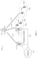
- FIG. 1 illustrates an exemplary communications system 100 that is used for hybrid beamforming.
- the communications system 100 includes a satellite 105 connected through satellite channels to gateways 110 and 125, and ground terminals 120a, 120b, 120c and 120d, which are located on a planetary surface, e.g., the surface of the Earth.
- a planetary surface e.g., the surface of the Earth.
- the illustrated example of communications system 100 shows one satellite and a limited number of gateways and ground terminals, various implementations can include different numbers of satellites, gateways and ground terminals without loss of generality.
- the following sections describe the planetary surface with respect to the Earth's surface. However, the techniques described are also applicable to other planetary surfaces.
- the satellite 105 transmits data to, and receives data, from the gateways 110, 125, and ground terminals 120a, 120b, 120c and 120d.
- Gateway 125 and ground terminals 120a and 120b are within a terrestrial region 130a that is covered by a formed beam.
- Ground terminals 120c and 120d are within a terrestrial region 130b that is covered by another formed beam. That is, gateway 125 and ground terminals 120a and 120b are located within the geographic extent covered by beam 130a, while ground terminals 120c and 120d are located within the geographic extent covered by beam 130b.
- the gateways 110 and 125 are terrestrially connected to each other and to a terrestrial network 135 through communications link 140.
- the satellite 105 can be located at a low earth orbit (LEO), a medium earth orbit (MEO), or a geostationary orbit (GEO) location defined by a longitude.
- the satellite 105 interconnects the gateway 110, the gateway 125 and the ground terminals 120a, 120b in beam 130a, and the ground terminals 120c, 120d in beam 130b, through satellite communications channels.
- the satellite 105 includes multiple antenna radiating elements or feeds to form beams for transmission of information between the satellite 105 and the gateways or ground terminals.
- the satellite 105 includes one or more beamformer processors to process active signal streams for beamforming.
- the satellite 105 also includes multiple HPAs that receive the active signal streams from the beamformer processor, and forwards the signal streams with amplification to feeds that are connected to the HPAs.
- the feeds transmit signals to or receive signals from the gateways 110, 125 and the ground terminals 120a-120d using the formed beams.
- a beam can encompass one or more gateways (e.g., beam 130a) within its coverage area, or a beam can encompass zero gateways (e.g., 130b).
- the beams 130a and 130b are hybrid analog/digital beams formed by the satellite 105.
- the beams 130a or 130b, or both, are digital beams that are generated by a digital beamformer on board the satellite by combining analog beams generated panels.
- the digital beams 130a or 130b, or both, are therefore hybrid beams formed within a cluster coverage area of the analog beams. While only two hybrid beams 130a and 130b are shown, more than two beams can be active at a time in various implementations, and any number of ground terminals can be distributed amongst a plurality of beam coverage areas.
- the number of hybrid beams that can be simultaneously active depends on the number of panels on the satellite used for generating analog beams, within the coverage area of which the digital beams are created. As described in greater detail below, in some implementations, the number of hybrid beams can range between tens to the order of thousands.
- a panel is a hardware structure that provides a surface on which the constituent feeds of the panel are positioned. Each panel can re-orient (e.g., tilt or move) the constituent feeds relative to other panels.
- a panel is a radiating antenna structure that can form one or more steerable analog beams.
- a panel is also referred to interchangeably as an analog beamformer, as noted previously.
- Each processor further supports 12.5 Megahertz (MHz) channelization x N (for any integer N > 0), with full mesh routing within a processor.
- the satellite 105 includes one beamformer processor with a configuration similar to that described above.
- the hybrid beamforming can be accomplished by space-based beamforming, i.e., on board the satellite, or ground-based beamforming (GBBF), e.g., using a system on Earth, or using a system that combines both space-based beamforming and GBBF.
- space-based beamforming the satellite 105 creates both analog beams using analog beamformers and digital beams using digital beamformer processors on board the satellite.
- the analog and digital beam coefficients are computed by one or more processing systems on the ground.
- the GBBF system creates the beams by applying the coefficients to the signals, and then sends beams to the satellite for transmission by forwarding through HPAs to the feeds.
- the GBBF system sends the coefficients to a beamformer processor onboard the satellite.
- the beamformer processor applies the coefficients to the active signal streams and control the HPAs and feeds for creating the beams.
- the satellite 105 creates analog beams on board the satellite, while GBBF computes digital beam coefficients using one or more processing systems on the ground.
- the GBBF system creates the digital beams using the digital coefficients, and sends the digital beams to the satellite.
- the GBBF system sends the digital coefficients to the satellite, which uses one or more digital beamformer processors to create the digital beams within the coverage areas of the analog beams.
- the satellite 105 includes multiple reflecting dishes for reflecting or redirecting the energy used to form the beams.
- a reflecting dish may be configured to redirect the beam formed by a given set of feeds.
- the analog beams can be formed by the satellite using different reflecting dishes to redirect the energy of their respective feeds.
- the orientation of the reflecting dishes can be configured such that the analog beams generate a cluster that covers a contiguous geographical area on the Earth's surface.
- the analog beams are generated such that their footprints overlap to some degree, e.g., either partially or completely, in the cluster. In such cases, digital beams are formed by combining the overlapping analog beams in the cluster.
- the analog beams are generated such that their footprints are non-overlapping in the cluster.
- digital beams are formed separately from the analog beams in the cluster.
- the shape of the cluster can be varied by adjusting the relative positions of the analog beams, as described in greater detail below.
- the satellite 105 then uses the digital beamformers to generate digital beams within the coverage areas of the clusters.
- the satellite 105 uses a set of steerable antennas, which are combined to generate digital beams.
- the antennas can be steered using phase shifters, e.g., orientation of the antennas can be changed by using different phase coefficients, or can be mechanically steered, e.g., using reflecting dishes, or mirror-based gimbals or beam-director units.
- the antennas can also be steered using other methods, e.g., by switching the antenna elements, or by using Risley prisms, phased-array optics, or microelectromechanical systems (MEMS) using micro-mirrors.
- MEMS microelectromechanical systems
- the reflecting dishes in the satellite 105 are mounted on gimbals to enable the satellite to dynamically rotate the reflecting dishes to change the analog beam locations on the surface of the Earth after satellite deployment and during subsequent satellite operation.
- This ability to rotate the reflecting dishes enables the satellite 105 to dynamically change its field of view during operation and, thereby, provides the satellite with much greater communications services coverage flexibility than typical reflecting satellites in that the satellite 105 is able to place analog beams in a much greater portion of the hemisphere of the Earth closest to the satellite by rotating the reflecting dishes as needed during satellite operation.
- Implementations using rotatable reflecting dishes are described in greater detail in US Patent No. 9,083,426 , titled “Satellite Beamforming,” which is incorporated herein by reference in its entirety.
- a subset of the feeds in the satellite 105 can be used for transmission in the forward direction from the satellite 105 to the gateways 110 and 125, and the ground terminals 120a-120d. These feeds are referred to as the forward link elements, transmit elements, or forward link feeds. Other feeds can be used for transmission in the return direction from the gateways 110, 125 and the ground terminals 120a-120d to the satellite 105. These feeds are referred to as the return link elements, return link feeds, receive elements, or receiving feeds.
- the gateways 110 and 125 are coupled to the network 135 through a communications link 140.
- the network 135 can be a non-public data network, a public data network or a combination of public and non-public data networks, e.g., the Internet.
- the communications link 140 can be a high-speed terrestrial connection, such as an optical connection with data rates in the range of gigabits per second.
- the communications link 140 can be a satellite communications channel through a satellite that is different from the satellite 105.
- the communications link 140 can be part of a closed network accessible only to components of the satellite communications system 100, or part of an open network that connects the gateway 110 to the network 135.
- the gateways 110 and 125 may include one or more modules that process signals exchanged with the satellite elements for beamforming.
- the gateways 110 and 125 may transmit signals to the satellite 105 over the satellite return links for phase and/or gain calibration for the return link and the forward link. This may be the case, for example, when a GBBF system is employed.
- the signals used for phase and/or gain calibration may include unique code words that identify such signals as being configured for phase and/or gain calibration.
- the satellite 105 may measure the phase and gain of the transmitted calibration signals to enable calibration and/or pointing correction.
- the communications link 140 may be part of a closed network accessible only to components of the satellite communications system 100, or may be part of an open network that connects the gateway 110 to the network 135.
- the ground terminals 120a-120d are computing devices or systems able to communicate data to and from the satellite 105 over satellite links.
- one or more of the ground terminals 120a-120d are enterprise terminals.
- a ground terminal can be a satellite dish that provides network connectivity to multiple devices at a location, such as an office building.
- one or more of the ground terminals 120a-120d are individual user terminals.
- a ground terminal can be a handheld mobile telephone or car phone, a laptop computer, desktop computer, or a phone booth.
- the ground terminals in separate coverage areas serviced by different clusters of hybrid beams communicate with each other and with the gateways 110 and 125 over the satellite 105 via the satellite links 145, 150 and 155.
- Each satellite link 145, 150 or 155 includes both an uplink to the satellite 105 and a downlink from the satellite 105.
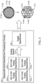
- FIG. 2 illustrates an example of a configuration of feeds in a spacecraft 200 for hybrid beamforming.
- the spacecraft 200 is a satellite, for example, the satellite 105.
- the spacecraft 200 includes multiple antenna elements or feeds, such as 202a, 202b, 202c and 202d.
- the feeds are divided into panels, such as 204a, 204b, 204c and 204d.
- Each feed e.g., 202a, 202b, 202c, or 202d, uses a phase shifter to form an analog beam, in combination with one or more other feeds.
- a feed can form one or more beams, by using a different phase shifter for each beam that it forms.
- the total number of feeds in the spacecraft 200 can range from tens to hundreds and thousands. For example, Table I below shows a configuration in which the spacecraft 200 has 8000 feeds.
- the feeds are divided into panels, e.g., as 204a, 204b, 204c and 204d, which is a subset of the feeds used for creating an analog beamformer.
- the number of feeds can be different for different panels.
- panel 204a includes six feeds
- panel 204b includes four feeds
- panel 204d includes two feeds.
- panels 204b and 204c each has the same number of feeds, e.g., four feeds.
- the number of feeds shown in the various panels in FIG. 2 are for illustrative purposes only. In various implementations, the number of feeds in each panel can be different, and can range from a small number, as shown here, to hundreds or thousands.
- Each panel forms a number of analog beams in the coverage area, with different panels reusing the frequency spectrum for forming the analog beams.
- Analog beams sharing the same frequency band overlap partially or fully, thereby forming a cluster, which is an area on the ground where digital beams are generated.
- Table I below shows an exemplary configuration that is represented by panels per cluster * number of clusters.
- the first row shows four panels, each of which forms analog beams for 16 clusters.
- the analog beams formed by a panel overlap with the analog beams formed by other panels.
- the 8000 feeds are divided amongst the four panels to form analog beams. Each feed uses a subset of the 128,000 phase shifters that are assigned to the feed to form analog beams in one or more clusters.
- Each panel e.g., each of 204a, 204b, 20c and 204d, is an analog beamformer panel.
- Each analog beamformer forms analog beams by combining the phase, delay, or amplitude, or any combination of these parameters, of some or all the feeds included the panel.
- One or more of these parameters are adjusted for each feed to combine into a single signal. Values of these parameter adjustments determine the location and the shape of the far-field coverage area on the Earth's surface, which is the area to be covered by the satellite footprint.
- One or more beamformer processors control some, or all, of the panels or analog beamformers to adjust one or more of the phase, delay and amplitude parameters of the constituent feeds such that the analog beams that are formed by these feeds point to an overlapping far-field coverage area on the Earth's surface.
- the overlapping coverage area is referred to as a cluster.
- the analog beams in each cluster are fed to one or more digital beamformer processing logic, which form hybrid beams, e.g., digital beams that are generated by combining the amplitude, phase, or delay, or a suitable combination of these parameters, of the analog beams.
- the hybrid beams have smaller coverage areas within the overlapping coverage area of the analog beams, e.g., within the cluster.
- a far field coverage area formed by analog beams generated by one or more panels of the spacecraft 200 e.g., panels 204a, 204b, 204c and 204d, among others, is represented by 210.
- One or more analog beams generated by the panels overlap in the far field coverage area within the region 212, which represents a cluster.
- One or more hybrid beams e.g., 214a, 214b, 214c and 214d, are generated within the cluster region 212 by combining the overlapping analog beams to create digital beams.
- each hybrid beam is a digital beam that is generated by combining underlying analog beams.
- the hybrid beams can be of different shapes and/or sizes.
- hybrid beams 214a and 214b are of the same size and shape.
- hybrid beam 214c is of a different size and shape than the beams 214a and 214b.
- Hybrid beam 214d is also of a different size and shape than the hybrid beams 214a, 214b and 214c.
- the number of hybrid beams that are formed in a cluster can vary from cluster to cluster. For example, some clusters may have a large number of hybrid beams. Some clusters may have only a single hybrid beam that is formed by combing all the analog beams corresponding to the cluster.
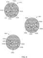
- FIG. 3 illustrates an example of a hybrid beamformer processing circuitry 302 in a spacecraft for generating hybrid beams, e.g., 314a, 314b, 314c and 314d, among others.
- the spacecraft hybrid beamformer processing circuitry 302 includes K analog beamformers ( K is an integer and K > 0), such as 304a, 304b, 304c and 304d.
- the spacecraft hybrid beamformer processing circuitry 302 also includes a digital beamformer 306.
- the spacecraft is a satellite, e.g., satellite 105, and the processing circuitry 302 is present in the satellite 105.
- the spacecraft hybrid beamformer processing circuitry 302 is also referred to as hybrid beamformer 302.
- the spacecraft hybrid beamformer processing circuitry 302 includes a combined onboard processor with logic for controlling the analog beamformers to form analog beams, and logic for the digital beamformer 306 to form digital beams. In some implementations, the spacecraft hybrid beamformer processing circuitry 302 includes separate onboard processors for controlling the analog beamformers that are different from the digital beamformer 306. The following description is applicable both implementations.
- Each analog beamformer e.g., 304a, 304b, 304c and 304d, is a panel that includes one or more feeds, as described above.
- there are four analog beamformers ( K 4), as shown in FIG. 3 .
- the analog beamformers correspond to direct radiating array (DRA) panels.
- Each DRA panel includes one or more feeds.
- the analog beamformers correspond to parabolic reflectors. In such cases, each analog beamformer is a parabolic reflector that includes one or more feeds. Other configurations of the analog beamformers are also possible.
- the spacecraft includes N ⁇ N feeds ( N is an integer and N > 0). In some implementations, N is on the order of hundreds or thousands, e.g., as shown in Table I.
- the N ⁇ N feeds are divided evenly among the four analog beamformers 304a, 304b, 304c and 304d, such that each analog beamformer includes N / 2 ⁇ N /2 feeds.
- the number of feeds included in an analog beamformer can vary, e.g., as discussed above with respect to the panels 204a, 204b, 204c and 204d.
- each analog beamformer controls the constituent N /2 ⁇ N / 2 feeds to generate Y analog beams (Y is an integer and Y > 0).
- an analog beamformer generates each analog beam by combining each of the constituent feeds. This is the case, for example, when there are Y phase shifters per feed.
- an analog beamformer generates each analog beam by combining a subset of the constituent feeds. In such cases, the number of phase shifters per feed can be less than Y.
- each feed can have Y phase shifters, but the analog beamformer does not use all the feeds for each beam.
- different analog beamformers can generate different numbers of analog beams.
- the K analog beamformers generate up to a total of K*Y analog beams.
- Analog beams from one or more analog beamformers overlap with each another in a far field coverage area, forming a cluster.
- analog beams 312a, 312b, 312c and 312d, among others overlap in part or in full to generate a cluster 314.
- one or more analog beams from each of the K analog beamformers overlap to form a cluster.
- a single cluster is generated by combining one analog beam from each analog beamformer. In such cases, up to a total of Y clusters are possible, since each analog beamformer can generate up to Y beams.
- one or more analog beams from a subset of the K analog beamformers overlap to form a cluster. For example, in some cases, one analog beam per analog beamformer across half the analog beamformers overlap in a cluster, thereby forming up to 2Y clusters.
- the spacing between the panels or analog beamformers is configured to maximize the communications capacity of the spacecraft by allowing a tighter cluster of beams, while limiting digital side lobes.
- the digital side lobes are also referred to as grating lobes, which are caused by the wide spacing between panel centers. The wider the spacing, the closer in are the digital side lobes or grating lobes to the main beam.
- maximizing the communications capacity refers to achieving a highest communications capacity of a communications link created by the satellite that is achievable in view of the physical constraints of the satellite hardware, or the communications medium (e.g., air), or both.
- maximizing the communications capacity refers to achieving an upper limit data rate that is configured by the satellite administrator.
- a larger spacing between the panels results in clusters that are closer together, allowing for a tighter cluster of beams, which thereby improves communication capacity.
- the digital beam gains are also closer to beam center of the underlying analog beams, and the gain roll off before a beam can re-use the frequency band is reduced.
- the larger inter-panel spacing also reduces the digital beam size, while improving the maximum capacity.
- too much increase in spacing can adversely impact performance due to interference from digital side lobes, which are described below.
- the K analog beamformers feed the K*Y analog beams to the digital beamformer 306 to generate hybrid beams.
- the digital beamformer 306 divides the corresponding frequency band into channels, and generates a digital beam for each channel by combining the analog beams in the cluster, as described previously.
- the digital beamformer 306 can generate potentially hundreds or thousands of digital beams covering the cluster area defined by the EOC of the analog beams in the cluster. For example, as shown in FIG.
- the digital beamformer 306 generates hybrid beams, such as 314a, 314b, 314c and 314d, in the cluster 3 14, where each hybrid beam is assigned a frequency channel that is a part of the overall frequency band covered by the analog beams in the cluster 314, such as analog beams 312a, 312b, 312c and 312d.
- hybrid beams such as 314a, 314b, 314c and 314d
- each hybrid beam is assigned a frequency channel that is a part of the overall frequency band covered by the analog beams in the cluster 314, such as analog beams 312a, 312b, 312c and 312d.
- the spacecraft hybrid beamformer processing circuitry 302 includes more than one digital beamformer.
- the spacecraft hybrid beamformer processing circuitry 302 functions as a hybrid beamformer that creates hybrid beams by generating digital beams using combinations of overlapping analog beams.
- the hybrid beamformer allows the analog beamformers, e.g., 304a, 304b, 304c and 304d, to support a large number of feeds and the digital beamformer e.g., 306, to create a large number of beams for providing coverage.
- the number of clusters that are formed correspond to the number of regions that have to be covered for communications coverage.
- the digital beamformers in the spacecraft are constrained to create the hybrid beams, i.e., the digital beams, within the coverage areas of the underlying analog beams.
- the analog beamformers combine the analog beams to provide the contours of the coverage areas in which the digital beams are generated.
- the hybrid beamformer supports up to K times the bandwidth; K times the coverage area; and higher EOC gain over most beams.
- the spacecraft hybrid beamformer processing circuitry 302 thereby addresses the hardware constraints of analog beamformers to support a large number of beams (e.g., in the order of hundreds or thousands), since every analog beam requires one phase shifter per feed, and addresses the processing constraints of digital beamformers to process a large number of feeds.
- the N ⁇ N feeds can be evenly divided among the K analog beamformers such that each analog beamformer gets N / K ⁇ N / K feeds. If each analog beamformer forms Y analog beams, then a total of K*Y analog beams are generated by the processing circuitry on board the spacecraft. In some implementations, K*Y analog beams are generated for transmitting data, and another K*Y analog beams are generated in the receive direction. For either direction, the K*Y analog beams are fed to digital beamformers.
- one or more onboard payload processors include Y digital beamformers, e.g., one for each analog beam in a cluster.
- each digital beamformer includes circuitry for K x K beamforming, e.g., K inputs and K outputs.
- the Y digital beamformers channelizes the available bandwidth into Z channels (Z is an integer and Z > 0), and generates Z digital beams within the cluster coverage area by combining the analog beams that overlap to form the cluster.
- Each digital beam is assigned one of the Z channels. Accordingly, a total of K*Y*Z hybrid beams are formed.
- the processing circuitry in a satellite includes 8 panels or analog beamformers, each with 16 ⁇ 16 feeds.
- the 8 analog beamformers correspond to 8 parabolic reflectors, with the feeds for each analog beamformer coupled to a separate parabolic reflector.
- Each analog beamformer forms 16 analog beams.
- the analog beamformer circuitry in the satellite therefore generates 128 analog beams in the transmit direction, and 128 analog beams in the receive direction.
- the transmit and receive analog beams are fed to a digital beamformer, which includes two processors.
- Each digital beamformer processor which is capable of 8x8 beamforming, has 64 input ports and 64 output ports, with 2.5 GHz bandwidth per port.
- Each processor divides the available bandwidth in to 12.5 MHz channels.
- a total of up to 22,000 hybrid beams, e.g., digital beams formed by combining the analog beams, can be generated with this configuration of the satellite processing circuitry for hybrid beamforming.
- each hybrid beam covers analog beamwidth corresponding to 3 decibels (3 dB).
- the available analog bandwidth in a cluster is divided into a large number of digital beams, e.g., the digital beams in each cluster can range from tens to hundreds or thousands.
- the number of digital beams generated in a cluster depends on a target degradation in signal power from the beam peak, e.g., center, of a digital beam to the edge of the digital beam.
- the target degradation in signal power is 0.5 dB such that the digital edge of cell is near the beam peak.
- a sufficient number of digital beams are generated such that the digital edge of cell. less than 0.5dB down compared to the beam peak.
- the peak gain of a digital beam e.g. the beam peak, is 10*log 10 ( K ) dB higher than analog beam, where K is the number of analog beamformers, as described above.
- a spacecraft e.g., a satellite
- the satellite uses transmit and receive antennas that utilize a hierarchical structure, in which multiple feeds are arranged in a panel, and multiple panels coordinate to form beams to cover a target area.
- Each panel uses analog amplitude (or gain), delay or phase adjustment, or any combination of these, to combine signals for multiple feeds in the panel, to create analog beams in clusters in the far field covering regions of the target area.
- the values of the amplitude (or gain), delay or phase adjustments determine positions of the far-field coverage areas.
- Digital beamformer processors use amplitude (or gain), delay or phase adjustment, or any combination of these, to combine analog beam signals from one or more panels to generate hybrid beams in each cluster. In this manner, the analog beamformer panels and the digital beamformer processors form hybrid beams in a hierarchical structure.
- the analog and digital amplitude (or gain), delay or phase adjustments are configurable, and modification of these parameters allows the clusters of coverage areas in the far field to be moved.
- the spacecraft e.g., satellite 105
- the spacecraft e.g., satellite 105
- the electronically steerable antennas are used in place of feeds to delineate coverage areas in which clusters of digital beams are formed.
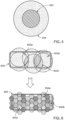
- FIGS. 4A and 4B present comparative illustrations of coverage provided respectively by analog and hybrid beams in a target area 400 on the Earth's surface.
- FIG. 4A shows analog beams, such as 402a, 402b and 402c, among others, covering regions in the target area 400, which is within the footprint 420 of a spacecraft, e.g., satellite 105.
- the analog beams are formed by analog beamformers described above.
- FIG. 4B shows clusters of hybrid beams, such as 410a, 410b and 410c, among others, providing coverage in similar regions in the target area 400.
- a hybrid analog/digital beamformer forms the hybrid beams in each cluster, e.g., 410a, 410b and 410c, by combining col-located or overlapping analog beams in the corresponding cluster to generate digital beams, each of which occupies a frequency channel in the overall spectrum covered by the analog beams in the cluster.
- each cluster e.g., 410a, 410b and 410c, includes many hybrid, i.e., digital beams.
- the coverage area of each cluster is larger, as shown, compared to the coverage area of an analog beam that is formed using all the feeds in the spacecraft.
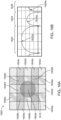
- FIG. 5 presents a comparative illustration of examples of coverage areas 502 and 504 respectively provided by a pure analog beam and overlapping analog beams formed using a hybrid beamformer.
- the coverage area 502 represents an area covered by an analog beam formed using all N ⁇ N feeds, e.g., when analog-only beamforming is used.
- the spacecraft includes K panels or analog beamformers, in which the N feeds are evenly divided among the K analog beamformers such that each analog beamformer gets N / K ⁇ N / K feeds
- coverage area 504 represents an area covered by overlapping analog beams in a cluster that includes one analog beam from each analog beamformer, e.g., when hybrid beamforming is used.
- Each analog beam in the coverage area 504 is formed by 1/ K feeds if all the feeds in a panel are used to form the analog beam.
- the beamwidth from the peak to the EOC in both coverage areas 502 and 504 is the same (e.g., 3 dB beamwidth EOC).
- the peak gain of the overlapping analog beams in the cluster is lower than the peak gain of analog-only beamforming.
- the peak gain of the analog beams in the coverage area 504 is 10log 10 ( K ) dB lower compared to that of the analog beam in the coverage area 502.
- the peak gain of the analog beams in the coverage area 504 is 6 dB less than the peak gain of the analog beam in the coverage area 502.
- the loss in peak gain for the analog beams in hybrid beamforming can be recovered by the hybrid beams.
- the peak gain of each hybrid beam is 10log 10 ( K ) dB higher than the underlying analog beams in the cluster.
- FIGS. 4A and 4B show approximately circular coverage areas, in some implementations, the coverage areas can be arbitrarily shaped to effectively cover users.
- FIG. 6 illustrates an example of hybrid beamforming to fully cover a non-circular shaped region 600.
- a spacecraft e.g., satellite 105, provides coverage to the region 600.
- the region 600 is part of a larger target area, e.g., the target area 400.
- a hybrid beamformer on board the spacecraft creates multiple analog beams, such as 602a, 602b and 602c, among others, that are spread out to fully cover the region 600. As shown, all the analog beams are not co-located.
- analog beams 602a and 602c partially overlap with one another, and analog beams 602b and 602c partially overlap with one another, but analog beams 602a and 602b do not overlap.
- the hybrid beamformer can cover an arbitrarily shaped target area.
- the hybrid beamformer combines the analog beams, e.g., 602a, 602b and 602c, among others, to create many (e.g. hundreds or thousands) of unique hybrid (e.g., digital) beams, such as 604a, 604b and 604c.
- the hybrid beamformer generates a sufficient number of hybrid beams so that the edge of cell of the digital beams is near the beam peak (e.g., less than 0.5 dB down from the beam peak to edge of cell), as described previously.
- the analog beams are spread out, the peak gain of a hybrid beam is lower, compared to the case where all the analog beams are co-located (e.g., in a circular coverage area).
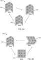
- FIGS. 7A and 7B illustrate examples of different cluster shapes that can be formed using hybrid beamforming.
- a cluster is an area on the ground that can support hybrid beams.
- a cluster is formed by overlapping, partly or fully, analog beams formed by analog beamformers, e.g., 304a, 304b, 304c and 304d shown previously.
- FIG. 7A shows that a cluster 702 can be approximately circular, e.g., when all the analog beams overlap with one another.
- a cluster can also be arbitrarily shaped, e.g., cluster 704. This is the case, for example, when the analog beams are spread out to cover the target area, such as described with respect to the region 600.
- clusters of different shapes, such as clusters 702 and 704 are formed to cover different regions of the target area, with these clusters coexisting.
- the shapes of the clusters are determined to meet specified performance requirements at EOC.
- a number of hybrid beams which are digital beams formed by combining the analog beams in a cluster, are generated for each cluster.
- cluster 702 includes hybrid beams 702a, 702b and 702c, among others
- cluster 704 includes hybrid beams 704a, 704b and 704c, among others.
- the number of hybrid beams can range from tens to hundreds or thousands.
- the hybrid beams are tightly packed together to provide continuous coverage in the region corresponding to the cluster, e.g., the hybrid beams 604a, 604b and 604c, among others, in the region 600.
- the hybrid beams are less densely packed to cover only areas where users are present.
- the hybrid beams 702a, 702b and 702c, among others, in the cluster 702 are less tightly packed than the hybrid beams 604a, 604b and 604c.
- the hybrid beams are spread out even further to cover selected portions in a cluster.
- clusters with different densities of hybrid beams coexist to cover different regions in a target area, where the different regions have different coverage requirements.
- clusters 702 and 704 can coexist with the respective configurations of hybrid beams as shown.
- hybrid beamforming clusters can be K times larger in area than for similar analog beams in analog-only beamforming (where K is the number of analog beamformers).
- the full frequency spectrum (uplink and downlink) can be re-used multiple times, and up to K times in some cases.
- the hybrid beams match the yield of the underlying analog beams with same or higher gain. In some implementations, wider bandwidth usage by the hybrid beams provides higher capacity because lower modulation codes are much more power efficient compared to higher modulation codes.
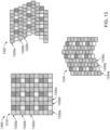
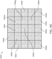
- FIG. 7B shows some examples of varying cluster shapes that can be achieved using hybrid beamforming.
- a hybrid beamformer e.g., the spacecraft hybrid beamformer processing circuitry 302 can form clusters shaped as in clusters 710a and 710f, square clusters such as 710b, parallelogram shaped clusters such as 710c and 710d, or semicylindrical shaped clusters such as 710e, among other cluster shapes.
- Each of the clusters 710a, 710b, 710c, 710d, 710e and 710f cluster shapes can fully re-use the frequency spectrum available for hybrid beamforming. The entire spectrum can be assigned to any part of a cluster.
- Combinations of these shapes overlapped in a single cluster can be created by segmenting the frequency band, and assigning each band segment to a different cluster shape. Size of any dimension of a cluster can also be adjusted. For example, in some implementations, up to +/- 10% of the optimal shape of a cluster can be adjusted with sacrificing 0.5 dB in gain, but without any change in the carrier to interference (C/I) ratio.
- C/I carrier to interference
- the hybrid beamformer processing circuitry executes one or more instructions to perform the process 800.
- These instructions are stored in memory, e.g., flash memory, hard disk or some other suitable memory, which is coupled to the hybrid beamformer on board the spacecraft.
- the instructions are sent to the hybrid beamformer on board the spacecraft from the ground, e.g., through satellite gateway 110 or 125.
- the process 800 starts at 802, in which a target area for communications coverage is determined.
- the hybrid beamformer processing circuitry 302 determines an area on the Earth's surface for communications coverage, such as target area 400.
- information about the target area e.g., coordinates of the area, are sent to the hybrid beamformer on board the spacecraft, e.g., as part of telecommunications commands from ground stations via the satellite gateways 110 or 125.
- the hybrid beamformer divides the target area into a plurality of regions.
- the hybrid beamformer processing circuitry 302 divides the target area 400 into a plurality of regions.
- the plurality of regions includes the region 600.
- the plurality of regions is determined based on the presence of user population in the target area, or the communications requirement in various regions, or both. For example, only regions in the target area where users are present are selected in some cases, while uninhabited areas are avoided. Additionally or alternatively, in some cases, areas where communications equipment are present, such as data gathering apparatus, or areas where users are predicted to be present within a known time period, such as a shipping channel in an ocean, are selected in some cases.
- the hybrid beamformer controls a subset of panels of feeds on the spacecraft to generate analog beams for each region, thereby forming a cluster, with each panel generating one or more analog beams of the cluster.
- the hybrid beamformer processing circuitry 302 controls the analog beamformers 304a, 304b, 304c and 304d to generate analog beams for each identified region of the target area where communications coverage is to be provided.
- An analog beamformer generates an analog beam by combining the phase, delay, gain, or any combination of these, of the feeds in the corresponding panel of the analog beamformer.
- one or more analog beams formed by each analog beamformer are provided to each region.
- each region is provided one analog beam from each analog beamformer. If an analog beamformer can form Y analog beams (e.g., there are Y phase shifters per feed in the panel), then up to Y clusters can be generated, thereby covering up to Y regions. With K panels present on the spacecraft, a total of up to K*Y analog beams can be generated, as described earlier.
- all the analog beams in a cluster can overlap, e.g., as shown with respect to analog beams 312a, 312b, 312c and 312d.
- the analog beams in a cluster can be spread out, e.g., as shown with respect to analog beams 602a, 602b and 602c.
- the shape of a cluster is determined by the number of analog beams present in the cluster, and the way the analog beams overlap. For example, if all the analog beams overlap to the greatest extent, such as analog beams 312a, 312b, 312c and 312d, then a circular shaped cluster is generated, such as cluster 702.
- clusters of arbitrary shapes can be formed, such as clusters 704, 710a, 710b, 710c, 710d, 710e and 710f.
- the number of analog beams in a region, and the relative positions of the analog beams in the region are determined to maximize the coverage gain over the region.
- the hybrid beamformer generates, in each cluster, one or more hybrid beams from the analog beams in the cluster, with each hybrid beam corresponding to a digital beam formed by combining one or more analog beams in the cluster.
- the hybrid beamformer processing circuitry 302 controls the digital beamformer 306 to generate, for each region, digital beams by combining the analog beams in the cluster corresponding to the region.
- the digital beamformer combines the magnitude, delay, or phase, or any combination of these parameters, of the analog beams in the region to form the digital beams for the region.
- each cluster of hybrid beams provides coverage over a wider area compared to analog beams formed using analog-only beamforming, e.g., as shown by clusters 410a, 410b and 410c in comparison to analog beams 402a, 402b and 402c.
- the relative positions of hybrid beams in a cluster can be different from that of other clusters.
- the coverage requirement depends, on the gain roll off from the peak to the EOC of the hybrid beams, or the locations of users, among other factors, as described previously.
- the hybrid beams can be tightly packed in a cluster, e.g., as shown with respect to hybrid beams 604a, 604b and 604c.
- the hybrid beams are tightly packed so that edge of digital beam roll off is negligible (e.g. less than 0.5 dB).
- the hybrid beams can be more loosely packed, e.g., as shown with respect to hybrid beams 702a, 702b and 702c, or the hybrid beams can be spread out such that some hybrid beams are distant from other hybrid beams in a cluster, e.g., as shown with respect to hybrid beams 704a, 704b and 704c.
- additional bandwidth is put into hybrid beams that require higher capacity.
- the available frequency spectrum within a region can be completely re-used up to K times (when there are K analog beamformers), depending on the relative distribution of the hybrid beams within the region.
- the frequency spectrum is reused a lower number of times than K, depending on the target C/I and the relative distribution of the hybrid beams within the region.
- the hybrid beamformer checks whether every region in the target area is covered. For example, after generating hybrid beams for a selected region in the target area 400, the hybrid beamformer processing circuitry checks whether hybrid beams for other identified regions in the target area are yet to be generated. If every region is not covered, e.g., one or more regions are remaining for which hybrid beams are yet to be generated, then the hybrid beamformer repeats the process at 806 and 808 until all the identified regions are covered. When hybrid beams have been generated for all the identified regions, then the hybrid beamforming generation process 800 ends.
- the spacecraft e.g., the satellite 105
- analog only hopping the spacecraft systematically changes the analog coefficients for the feeds in each panel to result in the cluster of hybrid beams hopping from one location to another. This has the effect of a cluster hopping from one location to another due to change in the coverage area of the overlapping analog beams. The relative positions and shapes of the hybrid beams within a cluster remain unchanged.
- analog only hopping is achieved by the analog beamformers making a single delay or gain adjustment to coefficients of the analog beams before the analog beams are fed to the digital beamformer processor.
- delay and gain adjustments on each analog signal ensures that the relative positions and performance of the digital beams are unchanged.
- the cluster 410a (or the cluster 410b, 410c, 702 or 704, among others) hops from a first location in a first time interval to a second location in the next time interval.
- the analog beamformer processors e.g., 304a, 304b, 304c and/or 304d, adjust the coefficients of the analog beams in the cluster 410 such that the terrestrial region covered by these beams changes.
- the coefficients of the digital beams formed by the digital beamformer using these analog beams remain unchanged, and therefore the relative positions and shapes of the hybrid beams within the cluster 410a remain unchanged.
- analog only hopping occurs in a scheduled repeating loop. For example, a cluster of digital beams will provide coverage to a first location for a first period of time; and then re-orient the corresponding analog beams to provide coverage to a second location for a second period of time, and so on, before returning to the first location to again provide coverage for the first period of time.
- the first period and second period are preselected.
- the first period and second period can be dynamically determined, depending on the coverage requirements.
- one or more periods are the same. In other implementations, every period is different.
- the hybrid beamformer processing circuitry on board the spacecraft changes both analog and digital coefficients to result in a cluster of hybrid beams hopping from one location to another.
- the relative positions and shapes of the digital beams within a cluster change, along with change in the location (and, in some implementations, shape) of the analog coverage area.
- the analog coefficients are adjusted on a scheduled repeating basis.
- the digital beam coefficients are also adjusted on a scheduled repeating basis, with adjustments to the digital beam coefficients synchronized with adjustments to the analog coefficients.
- analog/digital hopping results in changes to beam-to-beam routing as well as channel bandwidths.
- the digital beamformer processor 306 also adjusts the coefficients of the digital beams that are formed, and therefore the relative positions and/or shapes of the hybrid beams within the cluster 702 change, for example from the relative orientations of hybrid beams 702a, 702b and 702c to the relative orientations of hybrid beams 704a, 704b and 704c.
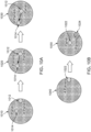
- FIG. 8B shows that in analog/digital hopping, a cluster 832 hops from a first location represented by 832a to a second location represented by 832b, and then to a third location represented by 832c, by changing the orientations of the analog beams.
- the relative positions and shapes of the hybrid beams within the cluster change, such that the overall shape of the cluster 832 in each location is different.
- the shape of the cluster 832 in location 832a is different from the shape of the cluster 832 in location 832b, which is different from the shape of the cluster 832 in location 832c.
- the hybrid beamformer processing circuitry on board the spacecraft changes the digital coefficients to result in digital coverage areas hopping within the analog coverage area.
- the relative positions and shapes of the hybrid beams within a cluster change, but the analog coverage area does not change.
- the digital beamformer 306 changes the digital coefficients for the cluster 702, such that the relative positions of the hybrid beams 702a, 702b and 702c within the cluster 702 changes from one time interval to another.
- the terrestrial region covered by the underlying analog beams in the cluster 702 does not change.
- the hopping patterns described above are enabled for any uplink or any downlink communications channel.
- a router in the processor on board the spacecraft facilitates a connection between a downlink and an uplink.
- the duration of each hop is configurable, e.g., by an operator of the spacecraft, such as a satellite network administrator.
- the time interval of coverage provided by the spacecraft in some regions can be different than the coverage time interval provided in some other regions.
- the analog coefficients, or digital coefficients, or both are configurable for each hop.
- the shape and size of a cluster can vary from one hop to another. Further, the relative positions and sizes of the digital beams in a particular cluster can also vary from one hop to another.
- the hybrid beams formed by a hybrid beamformer can of four beam types.
- a first hybrid beam type is full cluster beams, also referred to as "type 1" beams, which are clusters of digital beams that move over the coverage area and that are created using all the panels.
- type 1 beams a cluster includes one analog beam per panel for all the panels in the spacecraft, and digital beams are generated within the footprint of overlapping analog beams in the cluster.
- Type 1 beams can be used to provide coverage with either a uniform laydown of beams, or a non-uniform laydown of beams.
- the beam pattern is repeated across all digital beams in each cluster.
- a uniform or ordered pattern is used within a cluster, e.g., as shown with respect to hybrid beams 314a, 314b, 314c and 314d, but the pattern can vary from one cluster to another cluster.
- the hybrid or digital beams are distributed across the cluster using a frequency reuse plan.
- Uniform laydowns can support frequency re-use of the spectrum K times, where K is the number of panel s or analog beamformers.
- Ground terminals can access the spacecraft, e.g., satellite 105, from any location within the cluster.
- hybrid beams 922a and 922b reuse the same frequency channel twice; hybrid beams 924a and 924b reuse another frequency channel twice; and hybrid beam 926a and 926b reuse a third frequency channel twice.
- hybrid beams 932a, 932b and 932c reuse the same frequency channel three times; hybrid beams 934a and 934b reuse another frequency channel two times; and hybrid beam 936 uses a third frequency channel.
- a second hybrid beam type is partial cluster beams, also referred to as "type 2" beams, which are clusters of beams that move over the coverage area and that are created out of a subset of panels.
- type 2 beams a cluster includes analog beams generated by some of the panels in the spacecraft, and digital beams are generated within the footprint of overlapping analog beams in the cluster.
- a cluster with type 2 beams can be resized and/or reshaped as needed. Type 2 beams can be used in high capacity areas that are bandwidth limited locally and when only a subset of panels are available for use.
- LEO Low Earth Orbit
- a simple beam can be formed into any shape. During a pass over a target region, a simple beam can be reshaped to maintain a constant coverage area and Power Flux Density (PFD) levels.
- PFD Power Flux Density
- a single satellite spacecraft can support up to K simple beams, where K is the number of panels in the satellite. Each simple beam can completely reuse the frequency spectrum available to the spacecraft. In some cases, simple beams are used in power limited areas that have plenty of frequency spectrum.
- Type 3 or simple beams, and type 4 or split beams are single hybrid beams and not clusters of hybrid beams. Therefore, within the region covered by type 3 beams or type 4 beams, the available frequency is only used once. Accordingly, type 3 or type 4 beams are useful when user locations are packed so close that frequency reuse cannot be supported.
- hardware resources e.g. panels
- any or all of type 1, type 2, type 3 and type 4 beams are used to cover a target area, depending on traffic and coverage requirements.
- the spacecraft e.g., satellite 105
- hardware resources e.g., panels of feeds
- the hybrid beamformer circuitry on board the satellite uses more panels for a first cluster to cover a first region, and a lesser number of panels for a second cluster to cover a second region that is within the footprint of the satellite.
- the on board hybrid beamformer circuitry dynamically reconfigures the assignment of panels and increases the panels for the second cluster, while decreasing the number of panels for the first cluster.
- the satellite 105 moves along its trajectory and thereby across a coverage area on the ground, beam requirements to cover users in the coverage area can change. For example, at one point in the trajectory, users in a particular coverage region can be far away. As the satellite moves closer to the coverage region due to its movement along its orbit, the users in the coverage region gradually become closer to the satellite.
- the distance from the satellite to the users in the coverage region is the shortest of all positions along the satellite's orbit (here, positions refer to positions of the satellite along its orbit from where there is line of sight to the coverage region such that the satellite can provide communications coverage).
- the hybrid beamformer processing circuitry on board the satellite transfers panels from providing coverage to one area to providing coverage to another area.
- the transfer of panels is done dynamically and seamlessly so that there is minimal impact to the communications performance experienced by the user on the ground, and such that the underlying air interface (e.g., the communication protocol used to communicate between the satellite and a ground terminal) suffers minimal negative effects.
- panels are dynamically transferred from the first region to the second region to maximize performance and capacity. This effectively reduces the gain in the first region and expands its coverage to match PFD requirements. At the same time the gain in the second region is improved and the coverage area is narrowed.
- FIG. 11 illustrates an example of a process 1100 for resource transfer in hybrid beamforming.
- the process 1100 is performed by hybrid beamformer processing circuitry in a spacecraft, e.g., by hybrid beamformer processing circuitry 302, which includes one or more analog beamformer processors 304a, 304b, 304c and 304d, and one or more digital beamformer processors such as 306.
- the spacecraft is an orbiting satellite, such as the satellite 105. Accordingly, the following section describes the process 1100 with respect to the hybrid beamformer processing circuitry 302. However, the process 1100 also can be performed by other processing circuitry configurations, and/or by other types of spacecraft.
- the hybrid beamformer generates (i) one or more digital beams in the first cluster from the analog beams in the first cluster, and (ii) one or more digital beams in the second cluster from the analog beams in the second cluster.
- the hybrid beamformer processing circuitry 302 combines the analog beams in the first cluster to generate one or more digital beams to cover the region 1012.
- the hybrid beamformer processing circuitry 302 combines the analog beams in the second cluster to generate one or more digital beams to cover the region 1014.
- the hybrid beamformer controls (i) a third subset of feed panels on the spacecraft to generate a third group of analog beams for the first region in a third cluster and (ii) a fourth subset of feed panels on the spacecraft to generate a fourth group of analog beams for the second region in a fourth cluster.
- the hybrid beamformer processing circuitry 302 dynamically reassigns panels from covering the region 1012 to cover the region 1014, since the former region requires less panels for coverage near the nadir but the latter region requires more panels for coverage near the EOC, as described previously.
- the hybrid beamformer 302 assigns one panel to cover the region 1012, but assigns four panels to cover the region 1014, where some of these four panels were used to provide coverage in the region 1012 earlier in the first time interval.
- the hybrid beamformer 302 uses the one panel or analog beamformer to generate analog beams in a third cluster for the region 1012, and uses the four panels or analog beamformers to generate analog beams in a fourth cluster for the region 1014.
- the number of analog beams in the third cluster is different from the number of analog beams in the first cluster to cover the same region 1012
- the number of analog beams in the fourth cluster is different from the number of analog beams in the second cluster to cover the same region 1014.
- the number of analog beams in the third cluster is same from the number of analog beams in the first cluster
- the number of analog beams in the fourth cluster is same as the number of analog beams in the second cluster.
- the hybrid beamformer generates (i) one or more digital beams in the third cluster from the analog beams in the third cluster, and (ii) one or more digital beams in the fourth cluster from the analog beams in the fourth cluster.
- the hybrid beamformer processing circuitry 302 combines the analog beams in the third cluster to generate one or more digital beams to cover the region 1012.
- the hybrid beamformer processing circuitry 302 combines the analog beams in the fourth cluster to generate one or more digital beams to cover the region 1014.
- the hybrid beamformer forms hybrid beams in the third and fourth clusters for the regions 1012 and 1014 respectively.
- the hybrid beamformer forms a simple beam in the region 1012, and split beams in the region 1014. Accordingly, the number of hybrid beams in the third cluster is different from the number of hybrid beams in the first cluster to cover the same region 1012, and the number of hybrid beams in the fourth cluster is different from the number of hybrid beams in the second cluster to cover the same region 1014.
- the hybrid beamformer processing circuitry 302 on board the satellite 105 transfers hardware resources, e.g., panels from covering one region to covering a different region as the relative positions of these regions with respect to the satellite changes due to the satellite's movement.
- resource transfer i.e., transfer of one or more panels
- resource transfer i.e., transfer of one or more panels
- Changing from one relative location having a first set of communication characteristics or attributes for servicing that area to another location having a second set of communication characteristics or attributes for servicing that area triggers the spacecraft to perform resource transfer such that a different number of panels would be advantageous to properly service the locations as their locations change relative to the satellite.
- FIGS. 12A-12D illustrate examples of coverage flexibility provided by a spacecraft, e.g., satellite 105, using hybrid beamforming.
- a cluster is resized-either increased in size or decreased in size. Additionally or alternatively, a cluster can be reshaped.
- FIG. 12A shows an example of a cluster 1200 that is resized and/or reshaped at different time intervals of coverage. The cluster is reshaped from a first square shape 1202 to a second circular shape 1204. The cluster is resized in the circular shape among sizes 1204, 1206 and 1208 at various time intervals.
- the cluster is further reshaped from a circular shape 1208 to an arbitrary shape 1210 at another time interval.
- a cluster when a cluster is resized or reshaped, there is a change in the bandwidth capacity of the cluster. For example, when a cluster is decreased in size, the bandwidth capacity can be reduced. Alternatively, when a cluster is increased in size, the bandwidth capacity can be increased.
- the hybrid beamformer increases the number of clusters dynamically.
- FIG. 12C shows an example of increasing a number of clusters between groups 1232, 1234 and 1236.
- the hybrid beamformer 312 At a first time interval, the hybrid beamformer 312 generates a first number of clusters, including clusters 1232a, 1232b and 1232c, in group 1232.
- the clusters 1232a, 1232b and 1232c have dual polarization and double the capacity of clusters in the other groups 1234 and 1236.
- the hybrid beamformer reconfigures a single cluster as multiple clusters to create clusters by splitting. For example, in some cases, the hybrid beamformer forms two clusters by using a subset of the analog beamformer panels for each cluster, as described previously. For a P x Q array of beamformer panels (P x Q are integers > 0), the hybrid beamformer generates one cluster using P /2 x Q panels and the second cluster using the other P/2 x Q panels. In a similar manner, the hybrid beamformer can use other subsets of panels to create multiple sets of clusters out of hardware resources that were designed for a single high gain cluster.
- the hybrid beamformer can change the orientations of the analog beamformers, relative to the Earth's surface.
- arbitrarily steerable clusters can be formed.
- FIG. 12D shows an example of steerable clusters, e.g., 1252a, 1252b, 1252c, 1254a, 1254b, 1254c and 1256, formed using hybrid beamforming.
- the clusters can be circular in shape, e.g., clusters 1252a, 1252b and 1252c. Additionally or alternatively, the clusters can be square in shape, e.g., clusters 1254a, 1254b and 1254c.
- the clusters can be any arbitrary shape, e.g., cluster 1256, where a cluster is shaped to match the region to be covered.
- the clusters 1252a, 1252b, 1252c, 1254a, 1254b, 1254c and 1256 can be steered to any location on the Earth's surface.
- the hybrid beamformer can form a larger number of clusters at reduced/lower gain. Additionally or alternatively, the hybrid beamformer can cover larger areas, or shaped areas, at reduced gain. The hybrid beamformer also can form smaller clusters.
- a target area can be divided into regions and each region can be covered by a cluster of hybrid beams.
- the clusters of hybrid beams covering regions in a target area are arranged in rows and columns to provide contiguous coverage in the target area.
- rows of clusters are shifted horizontally, or columns of clusters are shifted vertically, or both, to effectively cover a target area, e.g., a target area that is of arbitrary shape.
- FIG. 13 illustrates an example of a group of clusters 1300 shifted horizontally, or vertically, or both, to cover a target area.
- a hybrid beamformer e.g., the hybrid beamformer processing circuitry 302 can cover a target area by forming a group of clusters of hybrid beams, such as the group of clusters 1300.
- Individual clusters in the group are arranged in rows and columns, e.g., rows 1320a, 1320b and 1320c, and columns 1330a, 1330b and 1330c.
- the rows and columns are arranged in a square configuration, e.g., configuration 1310, to cover the target area.
- the maximum frequency reuse of a cluster is P times Q (P columns by M rows of analog beamforming panels).
- hybrid beams within a predetermined range of a line parallel to the rows in the cluster are limited to a length within a preselected R degrees
- hybrid beams within a predetermined range of a line parallel to the panel columns are limited to a length within a preselected S degrees (where R and S are natural numbers).
- R is the distance between side lobes that appear in the horizontal direction
- S is the distance between side lobes that appear in the vertical direction.
- side lobes that are difficult to suppress appear along the vertical axis. Accordingly, the range limit S degrees is selected to avoid co-channel beam interference with the side lobes in the vertical direction.
- FIGS. 14A-14E illustrate an example of covering regions in a target area by hybrid beamforming using groups of clusters.
- a hybrid beamformer e.g., the hybrid beamformer 302 on board a spacecraft, such as satellite 105, forms a plurality of analog beams from the analog beamformer panels in the spacecraft.
- the hybrid beamformer 302 forms analog beams 1410a, 1410b and 1410c, among others, to cover a region in the target area.
- the analog beams are formed using some or all of the analog beamformers 304a, 304b, 304c and 304d.
- one beam from each analog beamformer is positioned and shaped over a desired coverage region in the target area.
- different numbers of beams from different analog beamformers are positioned and shaped over the desired coverage region.
- the row width is determined based on a distance between side lobes that appear in the horizontal direction.
- the row width is selected to minimize the interference from the side lobes. For example, as shown in FIG. 13A , if the horizontal distance between side lobes is within R degrees, then in some implementations, up to P co-channel hybrid beams are distributed in a row over a width no more than R degrees and nominally to around R*P /( P+ 1) degrees.
- the analog beams 1440a, 1440b and 1440c are time hopped versions of analog beams in another cluster, e.g., analog beams 1410a, 1410b and 1410c.
- the analog beams, e.g., 1440a, 1440b and 1440c, in the next region operate at a different hop time, polarization, or frequency, or any suitable combination of these parameters, compared to the analog beams in the next region, e.g., 1410a, 1410b and 1410c, to avoid interference from side lobes from the cluster 1420.
- the hybrid beamformer 302 subsequently generates digital beams by combining the analog beams 1440a, 1440b and 1440c, among others, as described previously.
- FIG. 14D shows a cluster 1440 of digital beams that is generated from the analog beams 1440a, 1440b and 1440c, among others to cover the desired region adjacent to the region covered by the cluster 1420.
- the digital beams in the cluster 1440 are also arranged in rows and columns, with the rows and columns in the cluster 1440 shifted to fit with the rows and columns in the cluster 1420.
- rows and columns are shifted such that co-channel hybrid beams (e.g., hybrid beams using the same frequency channel) are adjacent.
- neighboring clusters use different time hops, polarizations and/or time slots to avoid interference from side lobes generated by adjacent clusters.
- the hybrid beamformer 302 repeats the process of forming clusters of digital beams until all desired regions within the target area are covered. For example, as shown in FIG. 14E , after forming clusters 1420 and 1440, the hybrid beamformer covers a third desired region with a cluster 1450, as described with respect to FIGS. 14A-14D .
- clusters 1502 and 1504 use different frequency spectra.
- the effect of side lobes is mitigated by reusing frequencies across neighboring clusters. This is achieved by forming the digital beams for a first cluster using analog beams that are assigned to the first cluster and also analog beams that are assigned to neighboring clusters of the first cluster.
- the side lobes formed for in cluster 1502 destructively interfere in phase with the side lobes formed in cluster 1504 due to use of the same frequency bands in the two neighboring clusters. This results, for each cluster, in lower gain of the side lobes, which is within an acceptable threshold for interference in each cluster.
- side lobes 1520a, 1520b, 1520c and 1520d are formed in cluster 1502 when the hybrid beams are generated by combing the analog beams for clusters 1502 and 1504 using the frequencies shared between the two clusters.
- Non-adjacent clusters can use the same frequency, polarization and time hop since they do not interfere with one another.
- clusters 1602c and 1602d are non-adjacent clusters, while clusters 1602c and 1604b, and 1604b and 1602d, are pairs of adjacent clusters. Therefore, 1602c and 1602d share the same frequency, polarization and time hop.
- cluster 1604b has one or more of frequency, polarization or time hop different from clusters 1602c and 1602d.
- lobe 1626a which is the main analog beam lobe in the cluster 1626, can share frequency spectrum, time hops and polarization with the beam lobe 1622a in the center cluster 1622.
- a cluster that shares the same frequency, polarization and time hop with neighboring clusters generates hybrid beams using analog beams corresponding to the cluster itself, and also using analog beams of one or more neighboring cluster(s).
- cluster 1630c shares the same frequency, polarization and time hop with clusters 1630b and 1630d.
- Cluster 1630c forms digital beams by combining analog beams corresponding to cluster 1630c, and including analog beams corresponding to one or more of clusters 1630b and 1630d. This is similar to the hybrid beam forming described with respect to clusters 1502 and 1504.
- the interference of distant clusters is controlled by adjusting the side lobes of the analog beams using complex coefficients.
- digital beams fully fill the area.
- the digital beams within each cluster can have different frequency channels that reuse the frequency spectrum of the underlying analog beams, e.g., frequency spectrum shared by analog beams of the same cluster and neighboring cluster(s).
- the process 1700 starts at 1702, in which a target area for communications coverage is determined.
- the hybrid beamformer processing circuitry 302 determines an area on the Earth's surface for communications coverage, such as a target area shown with respect to FIGS. 14A-14E .
- information about the target area e.g., coordinates of the area, are sent to the hybrid beamformer on board the spacecraft, e.g., as part of telecommunications commands from ground stations to the satellite 105 via the satellite gateways 110 or 125.
- the hybrid beamformer 302 generates one or more analog beams from each analog beamformer 304a, 304b, 304c and 340d. In other implementations, the hybrid beamformer 302 generates one or more analog beams from a subset of the analog beamformers 304a, 304b, 304c and 340d.
- the hybrid beamformer selects another region of the plurality of regions neighboring the preceding processed region. For example, after generating the cluster 1420 of hybrid beams, the hybrid beamformer 302 selects the region neighboring the region covered by the cluster 1420, as described with respect to FIG. 14C .
- the hybrid beamformer checks whether every region in the target area is covered. For example, after generating the cluster 1420 of hybrid beams, the hybrid beamformer 302 checks whether all the desired regions in the target area have been covered by clusters of hybrid beams. Upon determining that the adjacent region (e.g., corresponding to cluster 1440) have not been covered, the hybrid beamformer 302 generates the cluster 1440 of digital beams as described above. Similarly, after generating the cluster 1440 of hybrid beams (and after generating a cluster for every desired region) the hybrid beamformer 302 checks whether all the desired regions in the target area have been covered by clusters of hybrid beams.
- the hybrid beamformer determines that all regions have not yet been covered, then the hybrid beamformer selects each uncovered region and generates a cluster for the selected region, as described with respect to 1714-1720. For example, after generating the cluster 1440, the hybrid beamformer 302 determines that a third region above the cluster 1420 is remaining. As such, the hybrid beamformer generates the cluster 1450 of hybrid beams, as described with respect to FIG. 14E .
- the processes and logic flows described in this document can be performed by one or more programmable processors executing one or more computer programs to perform functions by operating on input data and generating output.
- the processes and logic flows can also be performed by, and apparatus can also be implemented as, special purpose logic circuitry, e.g., an FPGA (field programmable gate array) or an ASIC (application specific integrated circuit).
- Computer readable media suitable for storing computer program instructions and data can include all forms of nonvolatile memory, media and memory devices, including by way of example semiconductor memory devices, e.g., EPROM, EEPROM, and flash memory devices; magnetic disks, e.g., internal hard disks or removable disks; magneto optical disks; and CD ROM and DVD-ROM disks.
- semiconductor memory devices e.g., EPROM, EEPROM, and flash memory devices
- magnetic disks e.g., internal hard disks or removable disks
- magneto optical disks e.g., CD ROM and DVD-ROM disks.
- the processor and the memory can be supplemented by, or incorporated in, special purpose logic circuitry.
- a communications channel may include the Web, where a user may interact with an interaction site via a webpage generated dynamically according to the interaction flow.
- a communications channel may include a smart phone application, where a user may interact with an interaction site by starting a smart phone application, and the smart phone application then contacts the interaction site and provides a communications interface between the user and the interaction site.
Landscapes
- Engineering & Computer Science (AREA)
- Computer Networks & Wireless Communication (AREA)
- Signal Processing (AREA)
- Physics & Mathematics (AREA)
- Astronomy & Astrophysics (AREA)
- Aviation & Aerospace Engineering (AREA)
- General Physics & Mathematics (AREA)
- Variable-Direction Aerials And Aerial Arrays (AREA)
- Aerials With Secondary Devices (AREA)
- Radio Relay Systems (AREA)
Claims (15)
- Appareil de formation de faisceaux destiné à générer des faisceaux hybrides, l'appareil de formation de faisceaux étant un engin spatial (105, 200), comprenant :une pluralité de sources (202a, 202b, 202c, 202d) configurées pour former des faisceaux analogiques, la pluralité de sources étant divisée en une pluralité de panneaux (204a, 204b, 204c, 204d), chaque panneau comprenant une ou plusieurs sources parmi la pluralité de sources ; etun circuit de traitement (302) configuré pour réaliser des opérations comprenant :la détermination d'une zone cible pour la couverture des communications ;la division de la zone cible en une pluralité de régions (1012, 1014, 1022, 1024) ;la génération, pour chaque région, d'une pluralité de faisceaux analogiques, un sous-ensemble de panneaux de la pluralité de panneaux générant un ou plusieurs faisceaux analogiques de la pluralité de faisceaux analogiques, et la pluralité de faisceaux analogiques couvrant chaque région formant un groupe ;la génération, dans chaque groupe, d'un ou plusieurs faisceaux hybrides, chaque faisceau hybride étant un faisceau numérique qui est généré par la combinaison d'un ou plusieurs faisceaux analogiques de la pluralité de faisceaux analogiques correspondant au groupe, chacun des un ou plusieurs faisceaux hybrides étant un faisceau numérique de groupe complet, les faisceaux de groupe complet étant des faisceaux de type 1 qui sont des groupes de faisceaux numériques qui se déplacent sur la zone de couverture et qui sont créés à l'aide tous les panneaux, un groupe de faisceaux de type 1 comprenant un faisceau analogique par panneau et les faisceaux numériques étant générés à l'intérieur d'une empreinte de faisceaux analogiques se chevauchant dans le groupe, etdans lequel le circuit de traitement est configuré pour réaliser des opérations comprenant en outre :la détermination d'une deuxième zone cible pour la couverture des communications ;la division de la deuxième zone cible en une pluralité de deuxièmes régions ;la génération, pour chaque deuxième région, d'une deuxième pluralité de faisceaux analogiques à l'aide d'un sous-ensemble de la pluralité de panneaux, chaque panneau du sous-ensemble générant un ou plusieurs faisceaux analogiques de la deuxième pluralité de faisceaux analogiques, et la deuxième pluralité de faisceaux analogiques couvrant chaque deuxième région formant un groupe de second type ; etla génération, dans chaque groupe de second type, d'une pluralité de faisceaux hybrides de groupe partiel à partir de la deuxième pluralité de faisceaux analogiques correspondant au groupe de second type, les faisceaux hybrides de groupe partiel étant des faisceaux de type 2 qui sont des groupes de faisceaux qui se déplacent dans la zone de couverture et qui sont créés à partir d'un sous-ensemble de panneaux, un faisceau de type 2 comprenant des faisceaux analogiques générés par un sous-ensemble des panneaux dans l'engin spatial, et des faisceaux numériques étant générés dans l'empreinte des faisceaux analogiques se chevauchant dans le groupe, et chaque faisceau hybride de groupe partiel étant un faisceau numérique généré par combinaison de phase d'un ou plusieurs faisceaux analogiques de la deuxième pluralité de faisceaux analogiques correspondant au groupe de second type.
- Appareil selon la revendication 1, comprenant en outre un ou plusieurs déphaseurs pour chaque source, dans lequel un nombre de faisceaux analogiques générés par un panneau correspond à un nombre de déphaseurs associés à chaque source incluse dans le panneau.
- Appareil selon la revendication 1, dans lequel la pluralité de faisceaux analogiques générés pour une région se chevauchent au moins partiellement dans la région ; facultativement, dans lequel
la génération de la pluralité de faisceaux analogiques pour une région comprend :la génération d'un nombre de faisceaux analogiques pour couvrir entièrement la région,dans lequel la forme du groupe est personnalisable pour couvrir entièrement la région. - Appareil selon la revendication 1, comprenant en outre des supports lisibles par machine qui stockent des coefficients de formation de faisceau numérique pour les faisceaux numériques, dans lequel les un ou plusieurs faisceaux hybrides d'un groupe sont générés à l'aide des coefficients de formation de faisceau numérique pour les faisceaux numériques ; facultativement, dans lequel la génération des un ou plusieurs faisceaux hybrides d'un groupe comprend :la détermination d'une largeur de faisceau numérique de sorte que la réduction du bord de couverture est dans les limites d'un seuil présélectionné de puissance au centre du faisceau numérique ;à l'aide de la largeur de faisceau numérique, le calcul d'un nombre de faisceaux numériques pour couvrir une zone correspondant au groupe ; etla génération du nombre calculé de faisceaux numériques dans le groupe.
- Appareil selon la revendication 1, dans lequel au moins un sous-ensemble des un ou plusieurs faisceaux hybrides dans un groupe partagent des fréquences de canal de communication à partir d'un spectre de fréquences attribué à la pluralité de faisceaux analogiques correspondant au groupe ; facultativement, dans lequel le circuit de traitement comprend un ou plusieurs processeurs formeurs de faisceaux, dans lequel chaque processeur formeur de faisceaux est configuré pour réaliser les opérations comprenant :la génération, pour chaque panneau, de faisceaux analogiques à l'aide des une ou plusieurs sources attribuées au panneau ; etla génération, dans chaque groupe, des un ou plusieurs faisceaux hybrides à partir de la pluralité de faisceaux analogiques correspondant au groupe.
- Appareil selon la revendication 1, dans lequel les orientations des groupes les uns par rapport aux autres sont basées sur l'espacement entre les panneaux, et dans lequel l'espacement entre deux panneaux est déterminé pour atteindre une capacité de canal de communication présélectionnée dans chaque groupe ;
facultativement, dans lequel la pluralité de faisceaux analogiques et les un ou plusieurs faisceaux hybrides pour une région sont respectivement générés à l'aide de coefficients de formation de faisceau analogique et de coefficients de formation de faisceau numérique, et dans lequel le circuit de traitement est en outre configuré pour réaliser des opérations comprenant :la génération d'une première pluralité de faisceaux hybrides dans un premier groupe à un premier moment selon un programme présélectionné ; etle réglage d'au moins l'un des coefficients de formation de faisceau analogique ou des coefficients de formation de faisceau numérique pour générer une deuxième pluralité de faisceaux hybrides dans un deuxième groupe à un deuxième moment selon le programme présélectionné. - Appareil selon la revendication 6, dans lequel la deuxième pluralité de faisceaux hybrides est différente de la première pluralité de faisceaux hybrides, et dans lequel au moins l'un des orientations relatives ou de l'acheminement des faisceaux hybrides dans le deuxième groupe est différent, respectivement, des orientations relatives ou de l'acheminement des faisceaux hybrides dans le premier groupe ;
ou, dans lequel la deuxième pluralité de faisceaux hybrides est identique à la première pluralité de faisceaux hybrides, et dans lequel les faisceaux hybrides du deuxième groupe sont générés à la suite de l'un d'un réglage de retard ou d'un réglage d'amplitude des faisceaux analogiques dans le deuxième groupe, le réglage de retard ou le réglage d'amplitude étant réalisé pour maintenir les orientations relatives et l'acheminement des faisceaux hybrides dans le deuxième groupe identiques à ceux des faisceaux hybrides dans le premier groupe. - Appareil selon la revendication 1, dans lequel le circuit de traitement est configuré pour réaliser des opérations comprenant en outre :la détermination d'une troisième zone cible pour la couverture des communications ;la division de la troisième zone cible en une pluralité de troisièmes régions ;la génération, pour chaque troisième région, d'une troisième pluralité de faisceaux analogiques à l'aide de la pluralité de panneaux, chaque panneau de la pluralité de panneaux générant un ou plusieurs faisceaux analogiques de la troisième pluralité de faisceaux analogiques, et la troisième pluralité de faisceaux analogiques couvrant chaque troisième région formant un groupe ; etla génération, dans chaque groupe, d'un faisceau hybride simple à partir de la troisième pluralité de faisceaux analogiques correspondant au groupe, les faisceaux hybrides simples étant des faisceaux de type 3, qui sont similaires aux faisceaux formés dans un réseau analogique à rayonnement direct qui utilise le même nombre total de sources, tous les panneaux étant utilisés pour créer un faisceau analogique, et un faisceau numérique unique étant généré à partir du faisceau analogique ; le faisceau hybride simple étant un faisceau numérique généré par combinaison de phase d'un ou plusieurs faisceaux analogiques de la troisième pluralité de faisceaux analogiques correspondant au groupe.
- Appareil selon la revendication 8, dans lequel le circuit de traitement est configuré pour réaliser des opérations comprenant en outre :la détermination d'une quatrième zone cible pour la couverture des communications ;la division de la quatrième zone cible en une pluralité de quatrièmes régions ;la génération, pour chaque quatrième région, d'une quatrième pluralité de faisceaux analogiques à l'aide d'un sous-ensemble de la pluralité de panneaux, chaque panneau du sous-ensemble générant un ou plusieurs faisceaux analogiques de la quatrième pluralité de faisceaux analogiques, et la quatrième pluralité de faisceaux analogiques couvrant chaque quatrième région formant un groupe de second type ; etla génération, dans chaque groupe de second type, d'un faisceau hybride divisé à partir de la quatrième pluralité de faisceaux analogiques correspondant au groupe de second type, les faisceaux divisés étant des faisceaux de type 4 avec une largeur de faisceau double par rapport à un faisceau simple, le nombre total de panneaux étant divisé en groupes, et chaque groupe de panneaux étant utilisé pour créer un faisceau différent d'une manière similaire à celle des faisceaux simples ; et le faisceau hybride divisé étant un faisceau numérique généré par combinaison de phase d'un ou plusieurs faisceaux analogiques de la quatrième pluralité de faisceaux analogiques correspondant au groupe de second type.
- Appareil selon la revendication 1, dans lequel la génération de la pluralité de faisceaux analogiques dans chaque région comprend la combinaison, dans chaque panneau, d'un ou plusieurs parmi la phase, le retard ou l'amplitude des sources dans le panneau, pour générer un faisceau analogique ;
facultativement, dans lequel la génération des faisceaux hybrides dans chaque groupe comprend la génération de faisceaux numériques dans chaque groupe en combinant un ou plusieurs parmi la phase, le retard ou l'amplitude d'un ou plusieurs faisceaux analogiques correspondant au groupe. - Procédé destiné à générer des faisceaux hybrides dans un appareil de formation de faisceaux, l'appareil de formation de faisceaux étant un engin spatial comprenant :la détermination d'une zone cible pour la couverture des communications ;la division de la zone cible en plusieurs régions (1012, 1014, 1022, 1024) ;la génération, pour chaque région, d'une pluralité de faisceaux analogiques à partir d'une pluralité de sources (202a, 202b, 202c, 202d) qui est divisée en une pluralité de panneaux (204a, 204b, 204c, 204d), chaque panneau comprenant une ou plusieurs sources parmi la pluralité de sources, un sous-ensemble de panneaux de la pluralité de panneaux générant un ou plusieurs faisceaux analogiques de la pluralité de faisceaux analogiques, et la pluralité de faisceaux analogiques couvrant chaque région formant un groupe, et un nombre de faisceaux analogiques générés par un panneau correspondant à un nombre de déphaseurs associés à chaque source incluse dans le panneau ; etla génération, dans chaque groupe, d'un ou plusieurs faisceaux hybrides, chaque faisceau hybride étant un faisceau numérique qui est généré par la combinaison d'un ou plusieurs faisceaux analogiques de la pluralité de faisceaux analogiques correspondant au groupe, les un ou plusieurs faisceaux hybrides d'un groupe étant générés par l'application de coefficients de formation de faisceau numérique pour les faisceaux numériques correspondants ;dans lequel chacun des un ou plusieurs faisceaux hybrides est un faisceau numérique de groupe complet, les faisceaux de groupe complet étant des faisceaux de type 1 qui sont des groupes de faisceaux numériques qui se déplacent sur la zone de couverture et qui sont créés à l'aide tous les panneaux, un groupe de faisceaux de type 1 comprenant un faisceau analogique par panneau et les faisceaux numériques étant générés à l'intérieur d'une empreinte de faisceaux analogiques se chevauchant dans le groupe, et le procédé comprenant en outre :la détermination d'une deuxième zone cible pour la couverture des communications ;la division de la deuxième zone cible en une pluralité de deuxièmes régions ;la génération, pour chaque deuxième région, d'une deuxième pluralité de faisceaux analogiques à l'aide d'un sous-ensemble de la pluralité de panneaux, chaque panneau du sous-ensemble générant un ou plusieurs faisceaux analogiques de la deuxième pluralité de faisceaux analogiques, et la deuxième pluralité de faisceaux analogiques couvrant chaque deuxième région formant un groupe de second type ; etla génération, dans chaque groupe de second type, d'une pluralité de faisceaux hybrides de groupe partiel à partir de la deuxième pluralité de faisceaux analogiques correspondant au groupe de second type, les faisceaux hybrides de groupe partiel étant des faisceaux de type 2 qui sont des groupes de faisceaux qui se déplacent dans la zone de couverture et qui sont créés à partir d'un sous-ensemble de panneaux, un faisceau de type 2 comprenant des faisceaux analogiques générés par un sous-ensemble des panneaux dans l'engin spatial, et des faisceaux numériques étant générés dans l'empreinte des faisceaux analogiques se chevauchant dans le groupe, et chaque faisceau hybride de groupe partiel étant un faisceau numérique généré par combinaison de phase d'un ou plusieurs faisceaux analogiques de la deuxième pluralité de faisceaux analogiques correspondant au groupe de second type.
- Procédé selon la revendication 11, dans lequel la génération d'une pluralité de faisceaux analogiques pour une région comprend :la génération d'une pluralité de faisceaux analogiques générés pour une région de sorte que la pluralité de faisceaux analogiques se chevauchent au moins partiellement dans la région ;facultativement, dans lequel la génération de la pluralité de faisceaux analogiques pour une région comprend :la génération d'un nombre de faisceaux analogiques pour couvrir entièrement la région, dans lequel une forme du groupe est personnalisable pour couvrir entièrement la région ;facultativement, dans lequel la génération des un ou plusieurs faisceaux hybrides dans un groupe comprend :la détermination d'une largeur de faisceau numérique de sorte que la réduction du bord de couverture est dans les limites d'un seuil présélectionné de puissance au centre du faisceau numérique ;à l'aide de la largeur de faisceau numérique, le calcul d'un nombre de faisceaux numériques pour couvrir une zone correspondant au groupe ; etla génération du nombre calculé de faisceaux numériques dans le groupe ;facultativement, dans lequel au moins un sous-ensemble des un ou plusieurs faisceaux hybrides dans un groupe partagent des fréquences de canal de communication à partir d'un spectre de fréquences attribué à la pluralité de faisceaux analogiques correspondant au groupe ; facultativement, les orientations des groupes les uns par rapport aux autres étant basées sur l'espacement entre les panneaux, et l'espacement entre deux panneaux étant déterminé pour atteindre une capacité de canal de communication présélectionnée dans chaque groupe ;facultativement, dans lequel la pluralité de faisceaux analogiques et les un ou plusieurs faisceaux hybrides pour une région sont respectivement générés à l'aide de coefficients de formation de faisceau analogique et de coefficients de formation de faisceau numérique, et le procédé comprenant en outre :la génération d'une première pluralité de faisceaux hybrides dans un premier groupe à un premier moment selon un programme présélectionné ; etle réglage d'au moins l'un des coefficients de formation de faisceau analogique ou des coefficients de formation de faisceau numérique pour générer une deuxième pluralité de faisceaux hybrides dans un deuxième groupe à un deuxième moment selon le programme présélectionné.
- Procédé selon la revendication 12, dans lequel la deuxième pluralité de faisceaux hybrides est différente de la première pluralité de faisceaux hybrides, et dans lequel au moins l'un des orientations relatives ou de l'acheminement des faisceaux hybrides dans le deuxième groupe est différent, respectivement, des orientations relatives ou de l'acheminement des faisceaux hybrides dans le premier groupe ;ou, dans lequel la deuxième pluralité de faisceaux hybrides est identique à la première pluralité de faisceaux hybrides, et dans lequel les faisceaux hybrides du deuxième groupe sont générés à la suite de l'un d'un réglage de retard ou d'un réglage d'amplitude des faisceaux analogiques dans le deuxième groupe, le réglage de retard ou le réglage d'amplitude étant réalisé pour maintenir les orientations relatives et l'acheminement des faisceaux hybrides dans le deuxième groupe identiques à ceux des faisceaux hybrides dans le premier groupe ;facultativement, dans lequel la génération de la pluralité de faisceaux analogiques dans chaque région comprend la combinaison, dans chaque panneau, d'un ou plusieurs parmi la phase, le retard ou l'amplitude des sources dans le panneau, pour générer un faisceau analogique ;facultativement, dans lequel la génération des un ou plusieurs faisceaux hybrides dans chaque groupe comprend la génération de faisceaux numériques dans chaque groupe en combinant un ou plusieurs parmi la phase, le retard ou l'amplitude d'un ou plusieurs faisceaux analogiques correspondant au groupe.
- Procédé selon la revendication 11, comprenant en outre :la détermination d'une troisième zone cible pour la couverture des communications ;la division de la troisième zone cible en une pluralité de troisièmes régions ;la génération, pour chaque troisième région, d'une troisième pluralité de faisceaux analogiques à l'aide de la pluralité de panneaux, chaque panneau de la pluralité de panneaux générant un ou plusieurs faisceaux analogiques de la troisième pluralité de faisceaux analogiques, et la troisième pluralité de faisceaux analogiques couvrant chaque troisième région formant un groupe ; etla génération, dans chaque groupe, d'un faisceau hybride simple à partir de la troisième pluralité de faisceaux analogiques correspondant au groupe, les faisceaux hybrides simples étant des faisceaux de type 3, qui sont similaires aux faisceaux formés dans un réseau analogique à rayonnement direct qui utilise le même nombre total de sources, tous les panneaux étant utilisés pour créer un faisceau analogique, et un faisceau numérique unique étant généré à partir du faisceau analogique ; le faisceau hybride simple étant un faisceau numérique généré par combinaison de phase d'un ou plusieurs faisceaux analogiques de la troisième pluralité de faisceaux analogiques correspondant au groupe.
- Procédé selon la revendication 14, comprenant en outre :la détermination d'une quatrième zone cible pour la couverture des communications ;la division de la quatrième zone cible en une pluralité de quatrièmes régions ;la génération, pour chaque quatrième région, d'une quatrième pluralité de faisceaux analogiques à l'aide d'un sous-ensemble de la pluralité de panneaux, chaque panneau du sous-ensemble générant un ou plusieurs faisceaux analogiques de la quatrième pluralité de faisceaux analogiques, et la quatrième pluralité de faisceaux analogiques couvrant chaque quatrième région formant un groupe de second type ; etla génération, dans chaque groupe de second type, d'un faisceau hybride divisé à partir de la quatrième pluralité de faisceaux analogiques correspondant au groupe de second type, les faisceaux divisés étant des faisceaux de type 4 avec une largeur de faisceau double par rapport à un faisceau simple, le nombre total de panneaux étant divisé en groupes, et chaque groupe de panneaux étant utilisé pour créer un faisceau différent d'une manière similaire à celle des faisceaux simples ; et le faisceau hybride divisé étant un faisceau numérique généré par combinaison de phase d'un ou plusieurs faisceaux analogiques de la quatrième pluralité de faisceaux analogiques correspondant au groupe de second type.
Applications Claiming Priority (6)
| Application Number | Priority Date | Filing Date | Title |
|---|---|---|---|
| US201662402028P | 2016-09-30 | 2016-09-30 | |
| US201762451043P | 2017-01-26 | 2017-01-26 | |
| US201762500589P | 2017-05-03 | 2017-05-03 | |
| US201762535282P | 2017-07-21 | 2017-07-21 | |
| US201762536135P | 2017-07-24 | 2017-07-24 | |
| PCT/US2017/054292 WO2018064474A1 (fr) | 2016-09-30 | 2017-09-29 | Formation de faisceaux hybrides analogiques/numériques |
Publications (4)
| Publication Number | Publication Date |
|---|---|
| EP3520332A1 EP3520332A1 (fr) | 2019-08-07 |
| EP3520332A4 EP3520332A4 (fr) | 2020-03-25 |
| EP3520332B1 true EP3520332B1 (fr) | 2025-04-09 |
| EP3520332B8 EP3520332B8 (fr) | 2025-06-25 |
Family
ID=61760190
Family Applications (2)
| Application Number | Title | Priority Date | Filing Date |
|---|---|---|---|
| EP17857497.6A Active EP3520332B8 (fr) | 2016-09-30 | 2017-09-29 | Formation de faisceaux hybrides analogiques/numériques |
| EP17857507.2A Pending EP3520168A4 (fr) | 2016-09-30 | 2017-09-29 | Fourniture d'une couverture de communication à l'aide d'une formation de faisceau analogique/numérique hybride |
Family Applications After (1)
| Application Number | Title | Priority Date | Filing Date |
|---|---|---|---|
| EP17857507.2A Pending EP3520168A4 (fr) | 2016-09-30 | 2017-09-29 | Fourniture d'une couverture de communication à l'aide d'une formation de faisceau analogique/numérique hybride |
Country Status (3)
| Country | Link |
|---|---|
| US (4) | US10554276B2 (fr) |
| EP (2) | EP3520332B8 (fr) |
| WO (2) | WO2018064496A1 (fr) |
Families Citing this family (23)
| Publication number | Priority date | Publication date | Assignee | Title |
|---|---|---|---|---|
| WO2018064496A1 (fr) | 2016-09-30 | 2018-04-05 | Jeffrey Freedman | Fourniture d'une couverture de communication à l'aide d'une formation de faisceau analogique/numérique hybride |
| US10848220B2 (en) * | 2017-03-08 | 2020-11-24 | Telefonaktiebolaget Lm Ericsson (Publ) | Compressing and decompressing beamspace coefficients |
| US10985833B2 (en) * | 2017-04-10 | 2021-04-20 | Viasat, Inc. | Coverage area adjustment to adapt satellite communications |
| EP3695531B1 (fr) | 2017-10-12 | 2025-08-27 | RKF Engineering Solutions LLC | Atténuation de l'affaiblissement dû à la pluie par formation de faisceau hybride |
| US11196156B2 (en) * | 2018-03-14 | 2021-12-07 | Metawave Corporation | Fixed wireless systems and methods incorporating a beam steering antenna |
| JP6789445B2 (ja) * | 2018-05-29 | 2020-11-25 | 三菱電機株式会社 | 中継局、制御局、データ伝送システム、データ伝送方法、制御回路およびプログラム |
| WO2020030712A1 (fr) * | 2018-08-08 | 2020-02-13 | Sony Corporation | Équipement d'infrastructure et dispositifs et procédés de communications |
| US20210344416A1 (en) * | 2018-09-04 | 2021-11-04 | Satixfy Israel Ltd. | Allocation of Downlink Carrier Power in LEO Communication Satellites |
| WO2020074213A1 (fr) | 2018-10-09 | 2020-04-16 | British Telecommunications Public Limited Company | Systèmes mimo |
| EP3654544A1 (fr) * | 2018-11-13 | 2020-05-20 | European Space Agency | Système d'antenne multifaisceaux reconfigurable |
| CN111817761A (zh) | 2019-04-10 | 2020-10-23 | 英国电讯有限公司 | 多输入多输出发送和接收 |
| CN110986963B (zh) * | 2019-12-25 | 2021-06-15 | 北京理工大学 | 基于姿态信息的航天器多目标在线聚类规划方法 |
| US11456521B2 (en) | 2020-04-02 | 2022-09-27 | Softbank Corp. | Controlling antenna beam generation to compensate for motion of a high-altitude platform |
| CN112490687B (zh) * | 2020-10-30 | 2022-10-28 | 西安空间无线电技术研究所 | 一种单口径多馈源多波束馈源组件的实现方法 |
| US12089063B2 (en) | 2020-11-06 | 2024-09-10 | Electronics And Telecommunications Research Institute | Method and apparatus for controlling beam in wireless communication system |
| CN112821925A (zh) * | 2021-01-21 | 2021-05-18 | 重庆邮电大学 | 一种基于大规模mimo天线阵列的混合波束赋形算法 |
| EP4302416A1 (fr) * | 2021-03-05 | 2024-01-10 | Telefonaktiebolaget LM Ericsson (publ) | Transmission de ressources de signal de référence à un seul port |
| CN113504549B (zh) * | 2021-07-15 | 2023-04-07 | 西安电子科技大学 | 基于广义旁瓣相消器的导航空时抗干扰方法 |
| WO2023108270A1 (fr) * | 2021-12-16 | 2023-06-22 | Macdonald, Dettwiler And Associates Corporation | Systèmes, procédés et terminaux pour la synchronisation de commande de rythme de signal entre un premier terminal et un second terminal |
| US20230217266A1 (en) * | 2021-12-30 | 2023-07-06 | Kythera Software, Inc. | Mobile platform clusters for communications cell transmission |
| US12088371B2 (en) * | 2022-02-14 | 2024-09-10 | Qualcomm Incorporated | Selection of beamforming configuration parameters for a multi-panel active antenna system (AAS) |
| CN116320977B (zh) * | 2023-03-29 | 2025-06-27 | 北京理工大学 | 卫星通信网络用户分簇与波束指向规划方法及系统 |
| WO2025184647A1 (fr) * | 2024-03-01 | 2025-09-04 | Ascendarc, Inc. | Réseau de formage de faisceau large analogue reconfigurable |
Citations (13)
| Publication number | Priority date | Publication date | Assignee | Title |
|---|---|---|---|---|
| EP2296225A1 (fr) * | 2009-09-10 | 2011-03-16 | Agence Spatiale Européenne | Architecture reconfigurable de réseau de formation de faisceaux |
| WO2011161198A1 (fr) * | 2010-06-23 | 2011-12-29 | Astrium Limited | Antenne |
| US20140334566A1 (en) * | 2013-05-10 | 2014-11-13 | Samsung Electronics Co., Ltd. | Apparatus and method for selecting transmit and receive beam in a wireless communication system |
| WO2015147445A1 (fr) * | 2014-03-24 | 2015-10-01 | Lg Electronics Inc. | Procédé de formation de faisceau hybride dans un système de communication sans fil, et appareil correspondant |
| WO2015156496A2 (fr) * | 2014-04-06 | 2015-10-15 | Lg Electronics Inc. | Procédé de détermination d'un poids de formation de faisceau numérique dans un système de communication sans fil, et appareil correspondant |
| US20150334726A1 (en) * | 2012-10-17 | 2015-11-19 | Southeast University | Wireless communication method utilizing a large-scale antenna array |
| US20160006122A1 (en) * | 2012-07-31 | 2016-01-07 | Samsung Electronics Co., Ltd. | Communication method and device using beamforming in wireless communication system |
| US20160142922A1 (en) * | 2014-11-17 | 2016-05-19 | Mediatek Inc. | Transceiver Architecture for Multiple Antenna Systems |
| US9398468B1 (en) * | 2014-12-29 | 2016-07-19 | Huawei Technologies Co., Ltd. | Cellular array with steerable spotlight beams |
| US20160254855A1 (en) * | 2015-02-27 | 2016-09-01 | Asia Satellite Telecommunications Company Limited | Methods and systems for improving spectrum utilization for satellite communications |
| US20160277990A1 (en) * | 2015-03-16 | 2016-09-22 | Space Systems/Loral, Llc | Communication system with multi band gateway |
| EP3076563A1 (fr) * | 2013-11-27 | 2016-10-05 | Samsung Electronics Co., Ltd. | Procédé de transmission mimo en boucle ouverte reposant sur une formation de faisceau hybride, et appareil correspondant |
| US10050654B2 (en) * | 2015-02-02 | 2018-08-14 | Airbus Defence And Space Sas | Method and system for suppressing a parasite signal received by a satellite payload |
Family Cites Families (31)
| Publication number | Priority date | Publication date | Assignee | Title |
|---|---|---|---|---|
| US5220320A (en) | 1988-03-11 | 1993-06-15 | Comsat | Switch matrix including both B switching elements and crossbar switch matrices |
| US6421528B1 (en) | 1999-04-29 | 2002-07-16 | Hughes Electronics Corp. | Satellite transmission system with adaptive transmission loss compensation |
| US8140658B1 (en) | 1999-10-06 | 2012-03-20 | Borgia/Cummins, Llc | Apparatus for internetworked wireless integrated network sensors (WINS) |
| US6307507B1 (en) * | 2000-03-07 | 2001-10-23 | Motorola, Inc. | System and method for multi-mode operation of satellite phased-array antenna |
| US6940452B2 (en) * | 2003-09-29 | 2005-09-06 | Northrop Grumman Corporation | Reducing co-channel interference in satellite communications systems by antenna re-pointing |
| US7511666B2 (en) * | 2005-04-29 | 2009-03-31 | Lockheed Martin Corporation | Shared phased array cluster beamformer |
| US7545323B2 (en) * | 2005-10-31 | 2009-06-09 | The Boeing Company | Phased array antenna systems and methods |
| US7898478B2 (en) | 2007-02-28 | 2011-03-01 | Samsung Electronics Co., Ltd. | Method and system for analog beamforming in wireless communication systems |
| EP2176923B1 (fr) | 2007-07-20 | 2018-05-30 | Astrium Limited | Système de simplification de traitement de réseau de formation de faisceaux configurables au sein d'une antenne à réseau phasé pour un satellite de télécommunications |
| US9521554B2 (en) | 2008-08-15 | 2016-12-13 | Qualcomm Incorporated | Adaptive clustering framework in frequency-time for network MIMO systems |
| EP2392048B1 (fr) * | 2009-02-02 | 2018-10-31 | Commonwealth Scientific and Industrial Research Organisation | Réseau d'antennes adaptatif hybride |
| US8385817B2 (en) | 2009-06-12 | 2013-02-26 | Viasat, Inc. | Multi-band satellite communication fade mitigation |
| US8743914B1 (en) | 2011-04-28 | 2014-06-03 | Rockwell Collins, Inc. | Simultaneous independent multi-beam analog beamformer |
| KR20130017572A (ko) | 2011-08-11 | 2013-02-20 | 삼성전자주식회사 | 하이브리드 빔포밍 시스템에서 아날로그 빔 결정 방법 및 장치 |
| US9124361B2 (en) | 2011-10-06 | 2015-09-01 | Raytheon Company | Scalable, analog monopulse network |
| US9379806B1 (en) | 2011-11-30 | 2016-06-28 | RKF Engineering Solutions, LLC | EIRP-based beamforming |
| US9083426B1 (en) | 2012-02-08 | 2015-07-14 | RKF Engineering Solutions, LLC | Satellite beamforming |
| KR20130127347A (ko) | 2012-05-10 | 2013-11-22 | 삼성전자주식회사 | 아날로그 및 디지털 하이브리드 빔포밍을 통한 통신 방법 및 장치 |
| EP2868005A1 (fr) | 2012-06-29 | 2015-05-06 | Agence Spatiale Européenne | Système et procédé de communication par satellite multifaisceaux, et charge utile de satellite permettant de mettre en oeuvre un tel procédé |
| US9748989B1 (en) | 2012-09-05 | 2017-08-29 | RKF Engineering Solutions, LLC | Rain fade mitigation in a satellite communications system |
| US20140210666A1 (en) * | 2013-01-25 | 2014-07-31 | Alexander Maltsev | Apparatus, system and method of wireless communication via an antenna array |
| US8948747B2 (en) | 2013-02-13 | 2015-02-03 | The Boeing Company | Overlapping cells for wireless coverage |
| CN105144600B (zh) | 2013-05-31 | 2018-11-02 | 英特尔Ip公司 | 用于大型天线阵列的混合数字和模拟波束成形 |
| EP3068060A4 (fr) * | 2013-11-04 | 2017-11-01 | LG Electronics Inc. | Procédé et appareil de transmission de signal dans un système de communications sans fil |
| US10211912B2 (en) | 2014-01-28 | 2019-02-19 | Mitsubishi Electric Corporation | Satellite communication system, satellite repeater, repeating method, communication network control station, satellite communication method, and method to perform data transmission |
| US9479964B2 (en) | 2014-04-17 | 2016-10-25 | Ubiqomm Llc | Methods and apparatus for mitigating fading in a broadband access system using drone/UAV platforms |
| US9848370B1 (en) | 2015-03-16 | 2017-12-19 | Rkf Engineering Solutions Llc | Satellite beamforming |
| US10187141B2 (en) | 2015-04-10 | 2019-01-22 | Viasat, Inc. | Cross-band system for end-to-end beamforming |
| US10158173B2 (en) | 2015-05-29 | 2018-12-18 | Huawei Technologies Co., Ltd. | Orthogonal-beam-space spatial multiplexing radio communication system and associated antenna array |
| WO2018064496A1 (fr) | 2016-09-30 | 2018-04-05 | Jeffrey Freedman | Fourniture d'une couverture de communication à l'aide d'une formation de faisceau analogique/numérique hybride |
| EP3695531B1 (fr) | 2017-10-12 | 2025-08-27 | RKF Engineering Solutions LLC | Atténuation de l'affaiblissement dû à la pluie par formation de faisceau hybride |
-
2017
- 2017-09-29 WO PCT/US2017/054334 patent/WO2018064496A1/fr not_active Ceased
- 2017-09-29 US US15/720,851 patent/US10554276B2/en active Active
- 2017-09-29 EP EP17857497.6A patent/EP3520332B8/fr active Active
- 2017-09-29 EP EP17857507.2A patent/EP3520168A4/fr active Pending
- 2017-09-29 US US15/720,828 patent/US10536202B2/en active Active
- 2017-09-29 WO PCT/US2017/054292 patent/WO2018064474A1/fr not_active Ceased
-
2020
- 2020-01-13 US US16/740,703 patent/US20200186220A1/en not_active Abandoned
- 2020-01-31 US US16/778,052 patent/US10903885B2/en active Active
Patent Citations (13)
| Publication number | Priority date | Publication date | Assignee | Title |
|---|---|---|---|---|
| EP2296225A1 (fr) * | 2009-09-10 | 2011-03-16 | Agence Spatiale Européenne | Architecture reconfigurable de réseau de formation de faisceaux |
| WO2011161198A1 (fr) * | 2010-06-23 | 2011-12-29 | Astrium Limited | Antenne |
| US20160006122A1 (en) * | 2012-07-31 | 2016-01-07 | Samsung Electronics Co., Ltd. | Communication method and device using beamforming in wireless communication system |
| US20150334726A1 (en) * | 2012-10-17 | 2015-11-19 | Southeast University | Wireless communication method utilizing a large-scale antenna array |
| US20140334566A1 (en) * | 2013-05-10 | 2014-11-13 | Samsung Electronics Co., Ltd. | Apparatus and method for selecting transmit and receive beam in a wireless communication system |
| EP3076563A1 (fr) * | 2013-11-27 | 2016-10-05 | Samsung Electronics Co., Ltd. | Procédé de transmission mimo en boucle ouverte reposant sur une formation de faisceau hybride, et appareil correspondant |
| WO2015147445A1 (fr) * | 2014-03-24 | 2015-10-01 | Lg Electronics Inc. | Procédé de formation de faisceau hybride dans un système de communication sans fil, et appareil correspondant |
| WO2015156496A2 (fr) * | 2014-04-06 | 2015-10-15 | Lg Electronics Inc. | Procédé de détermination d'un poids de formation de faisceau numérique dans un système de communication sans fil, et appareil correspondant |
| US20160142922A1 (en) * | 2014-11-17 | 2016-05-19 | Mediatek Inc. | Transceiver Architecture for Multiple Antenna Systems |
| US9398468B1 (en) * | 2014-12-29 | 2016-07-19 | Huawei Technologies Co., Ltd. | Cellular array with steerable spotlight beams |
| US10050654B2 (en) * | 2015-02-02 | 2018-08-14 | Airbus Defence And Space Sas | Method and system for suppressing a parasite signal received by a satellite payload |
| US20160254855A1 (en) * | 2015-02-27 | 2016-09-01 | Asia Satellite Telecommunications Company Limited | Methods and systems for improving spectrum utilization for satellite communications |
| US20160277990A1 (en) * | 2015-03-16 | 2016-09-22 | Space Systems/Loral, Llc | Communication system with multi band gateway |
Non-Patent Citations (1)
| Title |
|---|
| DERRYBERRY B ET AL: "RECONFIGURABLE ARRAYS FOR AIRBORNE RADARS", PROCEEDINGS OF THE NATIONAL TELESYSTEMS CONFERENCE. ATLANTA, MARCH 26 - 27, 1991; [PROCEEDINGS OF THE NATIONAL TELESYSTEMS CONFERENCE], NEW YORK, IEEE, US, vol. 1, 26 March 1991 (1991-03-26), pages 229 - 234, XP000266757, ISBN: 978-0-7803-0062-0, DOI: 10.1109/NTC.1991.148023 * |
Also Published As
| Publication number | Publication date |
|---|---|
| WO2018064496A1 (fr) | 2018-04-05 |
| EP3520332A4 (fr) | 2020-03-25 |
| US10554276B2 (en) | 2020-02-04 |
| US10903885B2 (en) | 2021-01-26 |
| EP3520168A4 (fr) | 2020-07-01 |
| WO2018064474A1 (fr) | 2018-04-05 |
| EP3520332A1 (fr) | 2019-08-07 |
| US20190028166A1 (en) | 2019-01-24 |
| EP3520332B8 (fr) | 2025-06-25 |
| US20200186220A1 (en) | 2020-06-11 |
| US20180123674A1 (en) | 2018-05-03 |
| US10536202B2 (en) | 2020-01-14 |
| US20200244328A1 (en) | 2020-07-30 |
| EP3520168A1 (fr) | 2019-08-07 |
Similar Documents
| Publication | Publication Date | Title |
|---|---|---|
| EP3520332B1 (fr) | Formation de faisceaux hybrides analogiques/numériques | |
| EP3695531B1 (fr) | Atténuation de l'affaiblissement dû à la pluie par formation de faisceau hybride | |
| US10903565B2 (en) | Architectures and methods for novel antenna radiation optimization via feed repositioning | |
| US6240072B1 (en) | Piecewise coherent beamforming for satellite communications | |
| CA2694008C (fr) | Systeme pour une simplification de traitement de reseau de formation de faisceau reconfigurable a l'interieur d'une antenne reseau a commande de phase pour un satellite de telecommunications | |
| US10333218B2 (en) | True time delay compensation in wideband phased array fed reflector antenna systems | |
| KR102541361B1 (ko) | 증가된 통신 용량을 갖는 위성 시스템 및 위성 시스템들의 용량을 증가시키는 방법들 | |
| CN1392634A (zh) | 天线系统 | |
| US10623066B2 (en) | High altitude platform cellular systems | |
| WO2001013543A1 (fr) | Systeme de communication par satellite a faisceaux fixes larges et a faisceaux etroits orientables | |
| US10887004B2 (en) | Telecommunications satellite, beamforming method and method for manufacturing a satellite payload | |
| Kilic et al. | Antenna aperture size reduction using subbeam concept in multiple spot beam cellular satellite systems | |
| Cornacchini et al. | A comparative analysis of frequency scanning and multispot beam satellite systems for mobile communications | |
| US11706765B2 (en) | Modifying a number of uplink or downlink information streams | |
| Marshack et al. | Next Generation Beam Forming Satellite Systems |
Legal Events
| Date | Code | Title | Description |
|---|---|---|---|
| STAA | Information on the status of an ep patent application or granted ep patent |
Free format text: STATUS: THE INTERNATIONAL PUBLICATION HAS BEEN MADE |
|
| PUAI | Public reference made under article 153(3) epc to a published international application that has entered the european phase |
Free format text: ORIGINAL CODE: 0009012 |
|
| STAA | Information on the status of an ep patent application or granted ep patent |
Free format text: STATUS: REQUEST FOR EXAMINATION WAS MADE |
|
| 17P | Request for examination filed |
Effective date: 20190425 |
|
| AK | Designated contracting states |
Kind code of ref document: A1 Designated state(s): AL AT BE BG CH CY CZ DE DK EE ES FI FR GB GR HR HU IE IS IT LI LT LU LV MC MK MT NL NO PL PT RO RS SE SI SK SM TR |
|
| AX | Request for extension of the european patent |
Extension state: BA ME |
|
| DAV | Request for validation of the european patent (deleted) | ||
| DAX | Request for extension of the european patent (deleted) | ||
| A4 | Supplementary search report drawn up and despatched |
Effective date: 20200225 |
|
| RIC1 | Information provided on ipc code assigned before grant |
Ipc: H04B 7/06 20060101ALI20200219BHEP Ipc: H04W 16/28 20090101ALI20200219BHEP Ipc: H04B 7/185 20060101ALI20200219BHEP Ipc: H04B 7/204 20060101ALI20200219BHEP Ipc: H04L 12/26 20060101AFI20200219BHEP |
|
| STAA | Information on the status of an ep patent application or granted ep patent |
Free format text: STATUS: EXAMINATION IS IN PROGRESS |
|
| 17Q | First examination report despatched |
Effective date: 20220824 |
|
| P01 | Opt-out of the competence of the unified patent court (upc) registered |
Effective date: 20230619 |
|
| REG | Reference to a national code |
Ref country code: DE Ref legal event code: R079 Free format text: PREVIOUS MAIN CLASS: H04L0012260000 Ipc: H04B0007060000 Ref country code: DE Ref legal event code: R079 Ref document number: 602017088858 Country of ref document: DE Free format text: PREVIOUS MAIN CLASS: H04L0012260000 Ipc: H04B0007060000 |
|
| GRAP | Despatch of communication of intention to grant a patent |
Free format text: ORIGINAL CODE: EPIDOSNIGR1 |
|
| STAA | Information on the status of an ep patent application or granted ep patent |
Free format text: STATUS: GRANT OF PATENT IS INTENDED |
|
| RIC1 | Information provided on ipc code assigned before grant |
Ipc: H04W 16/28 20090101ALI20240925BHEP Ipc: H04B 7/204 20060101ALI20240925BHEP Ipc: H04B 7/185 20060101ALI20240925BHEP Ipc: H04B 7/06 20060101AFI20240925BHEP |
|
| INTG | Intention to grant announced |
Effective date: 20241029 |
|
| GRAS | Grant fee paid |
Free format text: ORIGINAL CODE: EPIDOSNIGR3 |
|
| GRAA | (expected) grant |
Free format text: ORIGINAL CODE: 0009210 |
|
| STAA | Information on the status of an ep patent application or granted ep patent |
Free format text: STATUS: THE PATENT HAS BEEN GRANTED |
|
| AK | Designated contracting states |
Kind code of ref document: B1 Designated state(s): AL AT BE BG CH CY CZ DE DK EE ES FI FR GB GR HR HU IE IS IT LI LT LU LV MC MK MT NL NO PL PT RO RS SE SI SK SM TR |
|
| REG | Reference to a national code |
Ref country code: GB Ref legal event code: FG4D |
|
| REG | Reference to a national code |
Ref country code: CH Ref legal event code: EP |
|
| REG | Reference to a national code |
Ref country code: DE Ref legal event code: R096 Ref document number: 602017088858 Country of ref document: DE |
|
| REG | Reference to a national code |
Ref country code: IE Ref legal event code: FG4D |
|
| REG | Reference to a national code |
Ref country code: CH Ref legal event code: PK Free format text: BERICHTIGUNG B8 Ref country code: CH Ref legal event code: PK Free format text: BERICHTIGUNGEN |
|
| RAP2 | Party data changed (patent owner data changed or rights of a patent transferred) |
Owner name: RKF ENGINEERING SOLUTIONS LLC |
|
| RIN2 | Information on inventor provided after grant (corrected) |
Inventor name: HALVORSON, ERIK Inventor name: MARSHACK, DAVID Inventor name: MILLINER, DAVID Inventor name: KAPLAN, TED Inventor name: RUBIN, PHIL Inventor name: MANDELL, MICHAEL Inventor name: FREEDMAN, JEFFREY |
|
| REG | Reference to a national code |
Ref country code: DE Ref legal event code: R081 Ref document number: 602017088858 Country of ref document: DE Owner name: RKF ENGINEERING SOLUTIONS LLC, BETHESDA, US Free format text: FORMER OWNERS: FREEDMAN, JEFFREY, LAUREL, MD, US; HALVORSON, ERIK, VIENNA, VA, US; KAPLAN, TED, NORTH POTOMAC, MD, US; MANDELL, MICHAEL, FARMINGTON HILL, MI, US; MARSHACK, DAVID, BETHESDA, MD, US; MILLINER, DAVID, POTOMAC, MD, US; RUBIN, PHIL, WASHINGTON, D. C., US |
|
| REG | Reference to a national code |
Ref country code: NL Ref legal event code: MP Effective date: 20250409 |
|
| PG25 | Lapsed in a contracting state [announced via postgrant information from national office to epo] |
Ref country code: NL Free format text: LAPSE BECAUSE OF FAILURE TO SUBMIT A TRANSLATION OF THE DESCRIPTION OR TO PAY THE FEE WITHIN THE PRESCRIBED TIME-LIMIT Effective date: 20250409 |
|
| REG | Reference to a national code |
Ref country code: AT Ref legal event code: MK05 Ref document number: 1784496 Country of ref document: AT Kind code of ref document: T Effective date: 20250409 |
|
| PG25 | Lapsed in a contracting state [announced via postgrant information from national office to epo] |
Ref country code: PT Free format text: LAPSE BECAUSE OF FAILURE TO SUBMIT A TRANSLATION OF THE DESCRIPTION OR TO PAY THE FEE WITHIN THE PRESCRIBED TIME-LIMIT Effective date: 20250811 Ref country code: FI Free format text: LAPSE BECAUSE OF FAILURE TO SUBMIT A TRANSLATION OF THE DESCRIPTION OR TO PAY THE FEE WITHIN THE PRESCRIBED TIME-LIMIT Effective date: 20250409 Ref country code: ES Free format text: LAPSE BECAUSE OF FAILURE TO SUBMIT A TRANSLATION OF THE DESCRIPTION OR TO PAY THE FEE WITHIN THE PRESCRIBED TIME-LIMIT Effective date: 20250409 |
|
| REG | Reference to a national code |
Ref country code: LT Ref legal event code: MG9D |
|
| PG25 | Lapsed in a contracting state [announced via postgrant information from national office to epo] |
Ref country code: GR Free format text: LAPSE BECAUSE OF FAILURE TO SUBMIT A TRANSLATION OF THE DESCRIPTION OR TO PAY THE FEE WITHIN THE PRESCRIBED TIME-LIMIT Effective date: 20250710 Ref country code: NO Free format text: LAPSE BECAUSE OF FAILURE TO SUBMIT A TRANSLATION OF THE DESCRIPTION OR TO PAY THE FEE WITHIN THE PRESCRIBED TIME-LIMIT Effective date: 20250709 |
|
| PG25 | Lapsed in a contracting state [announced via postgrant information from national office to epo] |
Ref country code: PL Free format text: LAPSE BECAUSE OF FAILURE TO SUBMIT A TRANSLATION OF THE DESCRIPTION OR TO PAY THE FEE WITHIN THE PRESCRIBED TIME-LIMIT Effective date: 20250409 |
|
| PG25 | Lapsed in a contracting state [announced via postgrant information from national office to epo] |
Ref country code: BG Free format text: LAPSE BECAUSE OF FAILURE TO SUBMIT A TRANSLATION OF THE DESCRIPTION OR TO PAY THE FEE WITHIN THE PRESCRIBED TIME-LIMIT Effective date: 20250409 |
|
| PG25 | Lapsed in a contracting state [announced via postgrant information from national office to epo] |
Ref country code: HR Free format text: LAPSE BECAUSE OF FAILURE TO SUBMIT A TRANSLATION OF THE DESCRIPTION OR TO PAY THE FEE WITHIN THE PRESCRIBED TIME-LIMIT Effective date: 20250409 |
|
| PG25 | Lapsed in a contracting state [announced via postgrant information from national office to epo] |
Ref country code: AT Free format text: LAPSE BECAUSE OF FAILURE TO SUBMIT A TRANSLATION OF THE DESCRIPTION OR TO PAY THE FEE WITHIN THE PRESCRIBED TIME-LIMIT Effective date: 20250409 |
|
| PGFP | Annual fee paid to national office [announced via postgrant information from national office to epo] |
Ref country code: FR Payment date: 20250808 Year of fee payment: 9 |
|
| PG25 | Lapsed in a contracting state [announced via postgrant information from national office to epo] |
Ref country code: RS Free format text: LAPSE BECAUSE OF FAILURE TO SUBMIT A TRANSLATION OF THE DESCRIPTION OR TO PAY THE FEE WITHIN THE PRESCRIBED TIME-LIMIT Effective date: 20250709 |
|
| PG25 | Lapsed in a contracting state [announced via postgrant information from national office to epo] |
Ref country code: IS Free format text: LAPSE BECAUSE OF FAILURE TO SUBMIT A TRANSLATION OF THE DESCRIPTION OR TO PAY THE FEE WITHIN THE PRESCRIBED TIME-LIMIT Effective date: 20250809 |
|
| PG25 | Lapsed in a contracting state [announced via postgrant information from national office to epo] |
Ref country code: LV Free format text: LAPSE BECAUSE OF FAILURE TO SUBMIT A TRANSLATION OF THE DESCRIPTION OR TO PAY THE FEE WITHIN THE PRESCRIBED TIME-LIMIT Effective date: 20250409 |
|
| REG | Reference to a national code |
Ref country code: DE Ref legal event code: R097 Ref document number: 602017088858 Country of ref document: DE |
|
| PG25 | Lapsed in a contracting state [announced via postgrant information from national office to epo] |
Ref country code: SM Free format text: LAPSE BECAUSE OF FAILURE TO SUBMIT A TRANSLATION OF THE DESCRIPTION OR TO PAY THE FEE WITHIN THE PRESCRIBED TIME-LIMIT Effective date: 20250409 Ref country code: DK Free format text: LAPSE BECAUSE OF FAILURE TO SUBMIT A TRANSLATION OF THE DESCRIPTION OR TO PAY THE FEE WITHIN THE PRESCRIBED TIME-LIMIT Effective date: 20250409 |
|
| PG25 | Lapsed in a contracting state [announced via postgrant information from national office to epo] |
Ref country code: CZ Free format text: LAPSE BECAUSE OF FAILURE TO SUBMIT A TRANSLATION OF THE DESCRIPTION OR TO PAY THE FEE WITHIN THE PRESCRIBED TIME-LIMIT Effective date: 20250409 |
|
| PG25 | Lapsed in a contracting state [announced via postgrant information from national office to epo] |
Ref country code: RO Free format text: LAPSE BECAUSE OF FAILURE TO SUBMIT A TRANSLATION OF THE DESCRIPTION OR TO PAY THE FEE WITHIN THE PRESCRIBED TIME-LIMIT Effective date: 20250409 Ref country code: SK Free format text: LAPSE BECAUSE OF FAILURE TO SUBMIT A TRANSLATION OF THE DESCRIPTION OR TO PAY THE FEE WITHIN THE PRESCRIBED TIME-LIMIT Effective date: 20250409 |
|
| PG25 | Lapsed in a contracting state [announced via postgrant information from national office to epo] |
Ref country code: IT Free format text: LAPSE BECAUSE OF FAILURE TO SUBMIT A TRANSLATION OF THE DESCRIPTION OR TO PAY THE FEE WITHIN THE PRESCRIBED TIME-LIMIT Effective date: 20250409 |
|
| PLBE | No opposition filed within time limit |
Free format text: ORIGINAL CODE: 0009261 |
|
| STAA | Information on the status of an ep patent application or granted ep patent |
Free format text: STATUS: NO OPPOSITION FILED WITHIN TIME LIMIT |
|
| REG | Reference to a national code |
Ref country code: CH Ref legal event code: L10 Free format text: ST27 STATUS EVENT CODE: U-0-0-L10-L00 (AS PROVIDED BY THE NATIONAL OFFICE) Effective date: 20260218 |
|
| 26N | No opposition filed |
Effective date: 20260112 |