EP3520587B1 - Elektronische einheit mit reversiblen modulen - Google Patents
Elektronische einheit mit reversiblen modulen Download PDFInfo
- Publication number
- EP3520587B1 EP3520587B1 EP17781054.6A EP17781054A EP3520587B1 EP 3520587 B1 EP3520587 B1 EP 3520587B1 EP 17781054 A EP17781054 A EP 17781054A EP 3520587 B1 EP3520587 B1 EP 3520587B1
- Authority
- EP
- European Patent Office
- Prior art keywords
- connection
- electronic
- electronic unit
- module
- power supply
- Prior art date
- Legal status (The legal status is an assumption and is not a legal conclusion. Google has not performed a legal analysis and makes no representation as to the accuracy of the status listed.)
- Active
Links
Images




Classifications
-
- H—ELECTRICITY
- H05—ELECTRIC TECHNIQUES NOT OTHERWISE PROVIDED FOR
- H05K—PRINTED CIRCUITS; CASINGS OR CONSTRUCTIONAL DETAILS OF ELECTRIC APPARATUS; MANUFACTURE OF ASSEMBLAGES OF ELECTRICAL COMPONENTS
- H05K7/00—Constructional details common to different types of electric apparatus
- H05K7/14—Mounting supporting structure in casing or on frame or rack
- H05K7/1438—Back panels or connecting means therefor; Terminals; Coding means to avoid wrong insertion
- H05K7/1457—Power distribution arrangements
-
- H—ELECTRICITY
- H01—ELECTRIC ELEMENTS
- H01R—ELECTRICALLY-CONDUCTIVE CONNECTIONS; STRUCTURAL ASSOCIATIONS OF A PLURALITY OF MUTUALLY-INSULATED ELECTRICAL CONNECTING ELEMENTS; COUPLING DEVICES; CURRENT COLLECTORS
- H01R12/00—Structural associations of a plurality of mutually-insulated electrical connecting elements, specially adapted for printed circuits, e.g. printed circuit boards [PCB], flat or ribbon cables, or like generally planar structures, e.g. terminal strips, terminal blocks; Coupling devices specially adapted for printed circuits, flat or ribbon cables, or like generally planar structures; Terminals specially adapted for contact with, or insertion into, printed circuits, flat or ribbon cables, or like generally planar structures
- H01R12/50—Fixed connections
- H01R12/51—Fixed connections for rigid printed circuits or like structures
- H01R12/55—Fixed connections for rigid printed circuits or like structures characterised by the terminals
- H01R12/58—Fixed connections for rigid printed circuits or like structures characterised by the terminals terminals for insertion into holes
- H01R12/585—Terminals having a press fit or a compliant portion and a shank passing through a hole in the printed circuit board
-
- H—ELECTRICITY
- H05—ELECTRIC TECHNIQUES NOT OTHERWISE PROVIDED FOR
- H05K—PRINTED CIRCUITS; CASINGS OR CONSTRUCTIONAL DETAILS OF ELECTRIC APPARATUS; MANUFACTURE OF ASSEMBLAGES OF ELECTRICAL COMPONENTS
- H05K5/00—Casings, cabinets or drawers for electric apparatus
- H05K5/02—Details
- H05K5/0247—Electrical details of casings, e.g. terminals, passages for cables or wiring
-
- H—ELECTRICITY
- H05—ELECTRIC TECHNIQUES NOT OTHERWISE PROVIDED FOR
- H05K—PRINTED CIRCUITS; CASINGS OR CONSTRUCTIONAL DETAILS OF ELECTRIC APPARATUS; MANUFACTURE OF ASSEMBLAGES OF ELECTRICAL COMPONENTS
- H05K7/00—Constructional details common to different types of electric apparatus
- H05K7/14—Mounting supporting structure in casing or on frame or rack
- H05K7/1438—Back panels or connecting means therefor; Terminals; Coding means to avoid wrong insertion
- H05K7/1447—External wirings; Wiring ducts; Laying cables
- H05K7/1451—External wirings; Wiring ducts; Laying cables with connections between circuit boards or units
-
- H—ELECTRICITY
- H05—ELECTRIC TECHNIQUES NOT OTHERWISE PROVIDED FOR
- H05K—PRINTED CIRCUITS; CASINGS OR CONSTRUCTIONAL DETAILS OF ELECTRIC APPARATUS; MANUFACTURE OF ASSEMBLAGES OF ELECTRICAL COMPONENTS
- H05K7/00—Constructional details common to different types of electric apparatus
- H05K7/14—Mounting supporting structure in casing or on frame or rack
- H05K7/1438—Back panels or connecting means therefor; Terminals; Coding means to avoid wrong insertion
- H05K7/1459—Circuit configuration, e.g. routing signals
Definitions
- the present invention relates to the field of electronics in general but also, more particularly, that of aeronautical computing units.
- Computing units or bays each comprising a housing defining a compartment containing computation modules which can be inserted into the compartment in an insertion direction through an opening thereof and which can be connected to connectors carried by a bottom wall of the compartment. compartment to open into the compartment opposite the opening.
- the term “calculation module” is understood to mean any electronic circuit capable of processing signals and / or data, and in particular of performing calculations on these signals or these data.
- the electronic circuit can be a component of a computer and include a set of ASIC or other type processors, a programmable network of FPGA type, etc.
- the calculation modules are mainly connected to the control instruments on which acts the pilot of the aircraft, to indicators for the information of the pilot, to sensors distributed in the aircraft and to the equipment of the aircraft.
- An aim of the invention is to provide a solution to this problem.
- an electronic unit comprising a housing delimiting a compartment for receiving an electronic module in two directions opposite to each other from a direction of introduction.
- the compartment comprises electrical supply means for the electronic module and means for connecting the electronic unit to the electronic module, these means opening onto a connection face belonging to the compartment extending parallel to the direction of introduction.
- Such a configuration of the electronic unit allows easy installation and mounting of an electronic module regardless of the orientation of the electronic unit with respect to a partition or a maintenance access.
- the same electronic unit can then be used to equip spaces for receiving the electronic unit that are confined and in which the electronic units would be placed symmetrically with respect to one another.
- the supply means comprise a first conductive pad and a second conductive pad arranged on either side of a center line of the connection face, one of the first and second conductive pads being the positive pole of the supply. of the electronic module, the other of the first and second ranges conductive being the negative pole of the electronic module power supply.
- the face for connecting the electronic unit to the electronic module at least partially comprises a coating reducing friction.
- a face of the compartment opposite the connection face comprises at least one elastic element arranged to exert a force in a direction substantially perpendicular to the plane of the connection face, in order to avoid vibrations of the electronic module in the compartment.
- the means for connecting the electronic module to the electronic unit can comprise a magnetic coupler and / or an optical coupler.
- the invention also relates to an electronic module comprising two ends for introduction into a compartment of an electronic unit in two opposite directions of an introduction direction, means for connection to an electrical supply and means for connection to the. electronic unit, the means of connection to a power supply and the means of connection to the electronic unit opening onto a connection face belonging to the electronic unit, the connection face extending parallel to the direction of introduction.
- Such an electronic module can be easily installed in a compartment of an electronic unit. regardless of the orientation of the electronic unit in relation to a partition or a maintenance access. The same electronic module can then be used to equip electronic units which would be placed symmetrically with respect to one another.
- the means of connection to an electrical supply comprise means for restoring a constant supply polarity whatever the polarity of the voltage applied to the means of connection to an electrical supply.
- the electronic module is not damaged and can operate normally.
- the electronic module comprises means connected to the means of connection to an electric power supply and shaped to modify a direction of communication of the means of connection to the device.
- connection means of the electronic module can be modified as a function of the orientation of the electronic module relative to the housing.
- the invention also applies to an electronic module comprising at least one end for introduction into a compartment of an electronic unit in two directions opposite to a direction of introduction, means for connection to an electrical supply and means connection to the electronic unit, the connection means to a power supply and the connection means to the electronic unit opening onto a connection face belonging to the electronic module, the connection face extending parallel to the direction of introduction.
- the invention also applies to an aircraft comprising a fuselage comprising several electronic units described above and distributed in the fuselage, the fuselage being divided by a floor into an upper volume and a lower volume in which the supporting beams extend. the floor and delimiting with the fuselage and the floor two side housings which have a substantially triangular cross section and which extend parallel to a longitudinal direction of the fuselage, the electronic units being arranged in at least one of the side housings.
- the aircraft generally comprises a fuselage 1 divided by a floor 2 into an upper volume 3 and a lower volume 4.
- the upper volume 3 is intended to receive seats to accommodate travelers and constitutes the cabin of the aircraft.
- the lower volume 4 is intended to receive the luggage of travelers or freight and constitutes the hold of the aircraft.
- the lower volume 4 In the lower volume 4 extend beams 5 supporting the floor 2 and delimiting with the fuselage 1 and the floor 2 two side housings 6 which have a substantially triangular cross section and which extend parallel to a longitudinal direction L of the fuselage 1 on either side of a central or central zone 7.
- the side housings 6 run under the floor 2 cables 8 of the electrical harness 9 of the aircraft and one of the main pipes or air conditioning tubing 10 carrying the air blown into the upper volume 3 to cool it.
- the electrical harness 9 comprises cables used for the transmission of power and cables for the transmission of control and signal signals. data.
- the aircraft comprises computing units 100 each comprising a housing 101 defining a main compartment 102, a first auxiliary compartment 103 extending below the main compartment 102 and a second auxiliary compartment 104 extending behind an upper part of the first auxiliary compartment. 103 and behind a lower part of the main compartment 102.
- the housing 101 comprises a front opening 105 for access to the main compartment 102; two side openings 106 for access to the main compartment 102; two side openings 107, opposite one another, for access to the first auxiliary compartment 103; and two side openings 108, opposite one another, for access to the second auxiliary compartment 104.
- the front opening 105 is left open; the side openings 106 are closed by a removable panel 109; the side openings 107, 108 oriented towards the middle zone 7 are left open; the side openings 107, 108 facing away from the middle zone 7 are closed by a removable panel 110, 111.
- the removable panels are held in the closed position by a quick locking mechanism or by screws.
- the panels 110, 111 can be mounted on one or the other of the side openings 107, 108 depending on the mounting direction of the computing unit 100 in the side housing 6 as will be seen below.
- the main compartment 102 contains calculation modules, generally designated 122; the first auxiliary compartment 103 contains a common module, generally designated 123, for cooling and powering the computation modules 122; and the second auxiliary compartment 104 contains a common module, generally designated as 124, for interconnecting the calculation modules 122.
- the common modules 123, 124 provide a transversal function for the calculation modules 122.
- the calculation modules 122 can be inserted into the main compartment 102 in an insertion direction I through the front opening 105 of the housing 101 and can be connected to connectors 115 carried by a back wall 116 of the housing 101 so as to open into the main compartment 102 opposite the front opening 105.
- the computing modules 122 have an overhanging front face which is fixed to the housing 101 and which partially closes the opening 105 (this opening being completely closed when all the calculation modules 122 are in place).
- the connectors 115 are connected to cables of the electrical harness 9 mainly dedicated to the transmission of control signals and data so as to connect the calculation modules 122 mainly to the control instruments on which the pilot of the aircraft acts, to indicators for pilot information, to sensors distributed throughout the aircraft and to aircraft equipment.
- the calculation modules 122 include a printed circuit board carrying electronic control and / or power components: they are known in themselves and will not be detailed here.
- the calculation modules 122 also carry on their edge opposite the opening 105 a connector allowing their connection to a connector carried by one face of a printed circuit board 118 which separates the lower part of the bottom of the main compartment 102 and the second auxiliary compartment 104 and extends into the first auxiliary compartment 103.
- the computation modules 122 are mounted in the main compartment 102 by means of slides 117 which are fixed in the housing 1 to extend perpendicularly to the opening 105 and therefore parallel to the direction of insertion I.
- the slides 117 are made of a thermally conductive material to drain by conduction part of the heat produced by the electronic components of the calculation modules 122 towards the housing 101.
- the housing 101 is for this purpose made at least partly of thermally conductive material so as to allow evacuation to the outside of the heat produced by the operation of the calculation modules 122.
- the housing is provided with openings on its upper wall to allow the escape of a convective flow.
- the connector of the calculation modules 122 allowing their connection to the printed circuit board 118 comprises a projecting support 150 from which extend, parallel to the direction of insertion I, pins 151 elastically deformable in a plane transverse to their longitudinal axis. between a relaxed state and a deformed state, the pins 151 having a larger cross section in the relaxed state than in the deformed state.
- the corresponding connector of the printed circuit board 118 includes metallized holes 152 each intended to accommodate one of the pins 151 which is forcibly engaged in the metallized hole and is clamped therein in its deformed state.
- the printed circuit board 118 is not placed in a sealed enclosure against dust.
- the printed circuit board 118 is covered with a layer of electrically insulating material 153 which is pierced by the pins 151 when these are engaged in the metallized holes 152.
- the layer of electrically insulating material 153 is clamped between the supports 150 and the printed circuit board 118, which tends to close the tears caused by the pins 151 and prevents dust from entering between the modules calculation 122 and the printed circuit board 118.
- the electrically insulating material here is a silicone and more particularly a silicone vulcanizable at room temperature (or RTV for “Room Temperature Vulcanization”).
- RTV Room Temperature Vulcanization
- any material having an elastomeric behavior can be used, and in particular other types of silicone.
- the common module 123 is inserted into the first auxiliary compartment 103 by the lateral opening 107 oriented towards the middle zone 7 in an insertion direction P perpendicular to the insertion direction I.
- the common module 123 has a front face 112 in overhang which is fixed to the housing 101 and which closes the opening 107.
- the common module 124 is inserted into the second auxiliary compartment 104 by the lateral opening 108 oriented towards the middle zone 7 in an insertion direction P ′ perpendicular to the insertion direction I.
- the common module 124 has a front face projecting which is fixed to the housing 101 and which closes the opening 108.
- the common modules 123 and 124 both carry flexible contacts allowing them to be connected to conductive areas of the printed circuit board 118 which is itself connected, on the one hand, to the calculation modules 122 as has been done. mentioned above and, on the other hand, to a connector 119 carried by the bottom wall 116 and connected to the power and control cables of the electrical harness 9.
- the flexible contacts are arranged on both sides the other of a center line parallel to the direction of insertion such that the contacts intended to receive the power supply have a positive pole and a negative pole extending along a line perpendicular to the center line with one one of the poles above the center line and the other of the poles below the center line.
- the second auxiliary compartment 104 comprises a connection face 160 extending parallel to the direction of introduction P ', facing the printed circuit 118.
- a first conductive pad 161 and a second conductive pad 162 arranged on either side of the a center line 163 of the branch face 160 open onto the branch face 160.
- a central conductive pad 164 located on the middle line 163 also opens onto the branch face 160.
- the conductive pads 161, 162 and 164 are oblong and s 'extend in a direction parallel to the center line 163.
- the first conductive pad 161 is connected to a first track of the printed circuit 118 and constitutes a positive pole of a power supply 165
- the second conductive pad 162 is in turn connected to a second track of the printed circuit 118 and constitutes a negative pole of an electric power supply 165
- the central conductive track 164 constitutes a ground of the electric power supply trique 165.
- Magnetic couplers 166.1 to 166.12 also open out on the connection face 160.
- a first series of magnetic couplers comprises magnetic couplers 166.1 to 166.6 which extend symmetrically on either side of the center line 163 in the vicinity of 'a first opening 108 of the compartment 104.
- a second series of magnetic couplers comprises magnetic couplers 166.7 to 166.12 which extend symmetrically on either side of the center line 163 near a second opening 108 of the compartment 104 opposite the first opening 108.
- Optical couplers 167.1 to 167.4 also open onto the connection face 160.
- a first series of optical couplers comprises the optical couplers 167.1 and 167.2 which extend symmetrically on either side of the center line 163 near a first opening 108 of the compartment 104.
- a second series of optical couplers comprises optical couplers 167.3 and 167.4 which extend symmetrically on either side of the center line 163 near a second opening 108 of the compartment 104 opposite to the first opening 108.
- the first series of optical couplers 167.1 and 167.2 and the first series of magnetic couplers 166.1 to 166.6 are respectively symmetrical to the second series of optical couplers 167.3 and 167.4 and the second series of couplers magnetic 166.7 to 166.12 with respect to a median plane of the face 160 orthogonal to the median direction 163.
- the magnetic 166.1 to 166.12 and optical couplers 167.1 to 167.4 are connected to the printed circuit 118.
- the connection face 160 is covered with a thin layer 168 of PTFE and the face 169 opposite the connection face 160 comprises three springs 170.1 to 170.3 longitudinal lines extending parallel to the center line 163.
- the printed circuit 118 is connected, on the one hand, to the calculation modules 122 as was mentioned above and, on the other hand, to a connector 119 carried by the wall of the device. bottom 116 and connected to the power and control cables of the electrical harness 9.
- the module 124 is here of substantially parallelepipedal shape and comprises two insertion ends 125 and 126 respectively of the module 124 in the compartment 104 in two directions opposite to the direction of introduction P ′.
- the module 124 also includes a connection face 127 to the box 100 on which open out a first and a second flexible contact respectively, 171 and 172, arranged on either side of a center line 173 of the connection face 127.
- a third central flexible contact 174 located on the center line 173 also opens on the connection face 127.
- the flexible contacts 171, 172 and 174 extend in a direction parallel to the center line 173 and the connection face 127 extends parallel to the direction of introduction P '.
- Magnetic couplers 175.1 to 175.12 also open onto the connection face 127.
- a first series of magnetic couplers comprises magnetic couplers 175.1 to 175.6 which extend symmetrically on either side of the center line 173 near the end introduction 125.
- a second series of magnetic couplers comprises magnetic couplers 175.7 to 175.12 which extend symmetrically on either side of the center line 173 near the introduction end 126.
- Optical couplers 176.1 to 176.4 also open onto the connection face 127 and extend symmetrically on either side of the center line 173.
- a first series of optical couplers comprises optical couplers 176.1 and 176.2 which extend symmetrically on either side another from the midline 173 near the introducer end 125.
- a second series of optical couplers includes optical couplers 176.3 and 176.4 which extend symmetrically. ically on either side of the center line 173 near the introduction end 126.
- the first series of optical couplers 176.1 and 176.2 and the first series of magnetic couplers 175.1 to 175.6 are respectively symmetrical to the second series of optical couplers 176.3 and 176.4 and the second series of magnetic couplers 175.7 to 175.12 with respect to a median plane of the face 127 orthogonal to the median direction 173.
- the branch face 127 is covered with a thin layer 177 of PTFE.
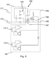
- the flexible contacts 171 and 172, the magnetic couplers 175.1 to 175.12 and optical couplers 176.1 to 176.4 are connected to an electronic circuit 180 which includes a first circuit 181 and a second circuit 182.
- the flexible contacts 171 and 172 are connected to the input terminals of a first circuit 181 which comprises a diode bridge 183.
- This first circuit 181 makes it possible to restore a constant supply polarity between its output terminals 184 and 185 whatever either the polarity of the voltage applied between the flexible contacts 171 and 172.
- the second circuit 182 is connected to the magnetic couplers 175.1 and 175.4 which are here emitters / receivers whose emission part is put in low impedance according to the polarity of the voltage applied between the flexible contacts 171 and 172.
- This setting in low impedance is effected by a MOS transistor 186 whose gate is subjected to the voltage applied between the flexible contacts 171 and 172.
- a Zener diode 187 protects the input of the MOS transistor 186 surges.
- the second circuit 182 makes it possible to modify the direction of communication of the couplers 175.1 and 175.4 as a function of the polarity of the voltage applied between the flexible contacts 171 and 172.
- the second circuit 182 being connected in the same way to the other magnetic couplers and optical, it therefore allows, in the same way, to modify the direction of communication of the magnetic couplers 175.1 to 175.12 and optical couplers 176.1 to 176.4 according to the polarity of the voltage applied between the flexible contacts 171 and 172.
- the module 123 also comprises a connection face 527 to the box 100 onto which emerge a first flexible contact 571 and a second flexible contact 572, arranged on either side of a center line 573 of the connection face 527.
- a third central flexible contact 574 located on the middle line 573 also opens onto the connection face 527.
- the flexible contacts 571, 572 and 574 extend in a direction parallel to the center line 573 and the connection face 527 extends parallel to the direction of introduction P.
- the connection face 527 may include aeraulic connectors (not shown) connected to fan 140 of module 123 and electrical connectors for operating monitoring.
- the calculation units 100 and 200 are respectively situated to the right and to the left of a longitudinal direction L of the fuselage 1 and have their respective frontal openings 105 and 205 opening out towards the front of the fuselage 1.
- the calculation units 300 and 400 are , as for them, respectively located on the right and to the left of a longitudinal direction L of the fuselage 1 and have their respective frontal openings 305 and 405 opening out towards the rear of the fuselage 1.
- the assembly of the common module 124 in the compartment 104 of the unit 100 is done by inserting the introduction end 126 of the common module 124 in the lateral opening 108 oriented towards the middle zone 7 of the compartment 104 in a direction of introduction P 'perpendicular to the longitudinal direction L, the connection face 127 being oriented towards the front of the fuselage 1.
- the respective PTFE layers 168 and 177 of the connection faces 160 and 127 are brought into contact under the effect of the longitudinal springs 170.1 to 170.3 and slide against one another.
- the positive pole formed by the first conductive pad 161 of the power supply electrical 165 of the second auxiliary compartment 104 is in electrical contact with the flexible contact 171 of the common module 124.
- the negative pole constitutes ued by the second conductive pad 162 of the power supply 165 of the second auxiliary compartment 104 is, for its part, in electrical contact with the flexible contact 172 of the common module 124.
- the first circuit 181 receives a voltage U 171-172 , measured between the first and second flexible contacts 171 and 172, positive .
- the second circuit 182 then passes the magnetic couplers 175.1 to 175.3 and 175.7 to 175.9 as well as the optical couplers 176.1 and 176.3 in “transmit” mode and the magnetic couplers 175.4 to 175.6, 175.9 to 175.12 and the optical couplers 176.2 and 176.4 in "mode” reception ”.
- the removal of the common module 124 from the second auxiliary compartment 104 is done by grasping the end 125 of the common module 124 in order to cause it to translate in the direction P ′. During this translation, the flexible contacts 171, 172 and 174 are pushed back by the connection face 160 and slide against the layer of PTFE 168 of the connection face 160 until the complete extraction of the common module 124 from the second. auxiliary compartment 104.
- the assembly of the common module 224 in the compartment 204 of the unit 200 is done by inserting the introduction end 225 of the common module 224 into the lateral opening 208 oriented towards the middle zone 7 of the second auxiliary compartment 204 in a direction introduction P 'perpendicular to the longitudinal direction L, the connection face 227 being oriented towards the front of the fuselage 1.
- the optical couplers 276.1 to 276.4 as well as the magnetic couplers 276.1 to 276.12 of the connection face 227 of the common module 224 respectively face the optical couplers 267.1 to 267.4 and the magnetic couplers 266.1 to 266.12 of the connection face 260 of the second auxiliary compartment 204.
- the positive pole formed by the first conductive pad 261 of the power supply 265 of the second auxiliary compartment 204 is in electrical contact with the flexible contact 271 of the common module 224.
- the negative pole formed by the second conductive pad 262 of the electrical supply 265 of the second auxiliary compartment 204 is, for its part, in electrical contact with the flexible contact 272 of the common module 224.
- the first circuit 281 receives a voltage U 271-272 , measured between the first and second flexible contacts 271 and 272, positive.
- the second circuit 282 then passes the magnetic couplers 275.1 to 275.3 and 275.7 to 275.9 as well as the optical couplers 276.1 and 276.3 in “emission” mode and the magnetic couplers 275.4 to 275.6, 275.10 to 275.12 and the optical couplers 276.2 and 276.4 in “mode” reception ”.
- the assembly of the common module 324 in the compartment 304 of the unit 300 is done by inserting the insertion end 326 of the common module 324 into the lateral opening 308 oriented towards the middle zone 7 of the second auxiliary compartment 304 in a direction introduction P 'perpendicular to the longitudinal direction L, the connection face 327 being oriented towards the rear of the fuselage 1.
- the optical couplers 376.1, 376.2, 376.3, 376.4 as well as the magnetic couplers 375.1 to 375.6 and 375.7 to 375.12 of the connection face 327 of the common module 324 respectively face the optical couplers 367.4, 367.3, 367.2 and 367.1 and the magnetic couplers 366.12 to 366.7 and 366.6 to 366.1 of the connection face 360 of the second auxiliary compartment 304.
- the positive pole formed by the first conductive pad 361 of the power supply 365 of the second auxiliary compartment 304 is in electrical contact with the flexible contact 372 d u common module 324.
- the negative pole formed by the second conductive pad 362 of the power supply 365 of the second auxiliary compartment 304 is, for its part, in electrical contact with the flexible contact 372 of the common module 324.
- the first circuit 381 receives a voltage U 371-372 , measured between the first and second flexible contacts 371 and 372, negative .
- the second circuit 382 then passes the magnetic couplers 375.1 to 375.3, 375.7 to 375.9 and the optical couplers 376.1 and 376.3 in "reception” mode and the magnetic couplers 375.4 to 375.6, 375.10 to 375.12 and the optical couplers 376.2 and 376.4 in "transmission mode ".
- the assembly of the common module 424 in the compartment 404 of the unit 400 is done by inserting the introduction end 425 of the common module 424 into the lateral opening 408 oriented towards the middle zone 7 of the second auxiliary compartment 404 in a direction introduction P 'perpendicular to the longitudinal direction L, the connection face 427 being oriented towards the rear of the fuselage 1.
- the optical couplers 476.1, 476.2, 476.3, 476.4 as well as the magnetic couplers 475.1 to 475.6 and 475.7 to 475.12 of the connection face 427 of the common module 424 respectively face the optical couplers 467.4, 467.3, 467.2, 467.1 and the magnetic couplers 466.12 to 466.7 and 466.6 to 466.1 of the connection face 460 of the second auxiliary compartment 404.
- the positive pole formed by the first conductive pad 461 of the power supply 465 of the second auxiliary compartment 404 is in electrical contact with the flexible contact 472 of the common module 424.
- the negative pole formed by the second conductive pad 462 of the power supply 465 of the second auxiliary compartment 404 is, for its part, in electrical contact with the flexible contact 472 of the common module 424.
- the first circuit 481 receives a voltage U 471-472 , measured between the first and second flexible contacts 471 and 472, negative.
- the second circuit 482 then passes the magnetic couplers 475.1, 475.2, 475.3 and the optical coupler 476.1 in “reception” mode and the magnetic couplers 475.4, 475.5, 475.6 and 476.2 in “transmission” mode.
- a single model of calculation unit is then obtained which cooperates with a single type of module and which can be mounted in four different configurations without modifications. The costs of certification, production, maintenance and installation are thus greatly reduced.
- calculation unit 100 The elements identical or analogous to those of the calculation unit 100 will include a numerical reference increased respectively by four hundreds in the following description of a particular embodiment of a calculation unit according to the invention.
- connection face 560 of the second auxiliary housing 504 comprises five conductive tracks 561, 562, 564, 590 and 591.
- the first conductive pad 561 is connected to a first track of the printed circuit 518 and constitutes a positive pole of a power supply 565
- the second conductive pad 562 is for its part connected to a second track of the printed circuit 518 and constitutes a negative pole of an electrical supply 565.
- the central conductive track 564 constitutes a ground of the electrical supply 565.
- the additional tracks 590 and 591 which extend symmetrically with respect to middle line 563 are communication input and output ports, respectively.
- Magnetic couplers 592.1 to 592.5 also open onto the connection face 560. These magnetic couplers extend symmetrically on either side of the center line 563 near a first opening 508 of the compartment 504.
- the printed circuit 518 comprises a metal plate 593 extending over the entire connection surface 560 and on which are fixed the conductive pads 561, 562, 564, 590, 591 as well as the windings of the magnetic couplers 592.1 to 592.5.
- the layer of PTFE 568 covers the plate 593 and includes a reservation in line with the conductive areas 561, 562, 564, 590, 591.
- the printed circuit 518 also includes cylinders 594.1 to 594.5 for shielding the magnetic couplers 592.1 to 592.5 s 'extending near the face of plate 593 opposite layer 568.
- connection face 527 of the common module 524 also comprises a metal plate 594 extending over the entire connection surface 560 and on which are fixed flexible contacts 571, 572, 574, 595, 596 as well as the windings of the magnetic couplers 597.1 to 597.5.
- the flexible contacts 571, 572, 574, 595, 596 respectively comprise three elastic bridges 571.1 to 571.3, 572.1 to 572.3, 574.1 to 574.3, 595.1 to 595.3, 596.1 to 596.3.
- the layer of PTFE 577 covers the plate 594 and includes a reservation in line with the conductive areas 571, 572, 574, 595, 596.
- the connection face 560 also includes cylinders 598.1 to 594.5 for shielding the magnetic couplers 592.1 to 592.5 extending near the face of plate 593 opposite to layer 568.
- the magnetic couplers 597.1 to 597.5 of the common module 524 face the magnetic couplers 592.1 to 592.5 of the computing unit 500, thus ensuring the magnetic coupling of the unit 500 and of the module 524.
- the elastic jumpers of the flexible contacts 571 , 572, 574, 595 and 596 respectively come into contact with the conductive pads 561, 562, 564, 590 and 591, supplying the common module 524 with the power supply 565 and placing the common module 524 in communication with the computing unit 500.
- the facing metal plates 593 and 594 provide efficient capacitive coupling between the common module 524 and the computing unit 500.
- the removal of the common module 524 from the second auxiliary compartment 504 is done by grasping the end 525 of the common module 524 in order to cause it to translate in the direction P ′. During this translation, the bridges of the flexible contacts 571, 572 and 574 are pushed back by the connection face 560 and slide against the layer of PTFE 568 of the connection face 560 until the complete extraction of the common module 524. of the second auxiliary compartment 104 ( figures 17 to 19 .
- the calculation units 100 are arranged in at least one of the side housings 6 such that the insertion direction I is substantially parallel to the longitudinal direction L of the fuselage 1. It will be noted that the removal of the panel 109 makes it possible to directly access the calculation module 122 closest to the middle zone 7.
- the calculation units 100 are mounted in pairs in adjacent positions in the side housings 6 such that the bottom walls 116 of the housings 101 extend opposite one another. Cables 8 of the wiring harness 9 are brought between the two computing units 100 to be connected to them via the connectors 115 and 119, which facilitates the connection of the computing units 100 to the electrical harness 9.
- the common module 123 comprises an outside air intake 120 which opens into the central zone 7 and which is associated with a fan 140 for introducing air into the common module 123 and with a second non-return valve 130.2 arranged to allow an air passage from the fan 140 to the common module 123 and oppose an air circulation in the opposite direction.
- the common module 123 has a top wall provided with air exhaust openings to the main compartment 102.
- the fan 140 here comprises a paddle wheel 141 driven, by an electric motor not shown, in rotation in a housing 142.
- the housing 142 comprises two walls 143 perpendicular to the axis of rotation of the impeller 141 joined by a circular peripheral wall 144 surrounding the impeller 141 which extends between the walls 143.
- One of the walls 143 is fixed to the wall of the common module 123 and the other of the walls 143 is provided with air exhaust ports 145 in the vicinity of the circular peripheral wall 144 while being spaced from the circular peripheral wall 144.
- the circular peripheral wall 144 extends around the impeller 141 and having a lower part tangentially extended by a vertical tangential passage 146 to which a receptacle 147 is attached.
- the paddle wheel 141 comprises a hollow hub forming a duct in communication with the air intake 120 such that the rotation of the paddle wheel 141 tends to entrain the air coming from the air intake 120 towards the orifices 145 of the casing 142.
- the dust which could be in the air flow is entrained by a centrifugal effect against the circular peripheral wall 144 until ue in the vertical tangential corridor 146 and the receptacle 147 where the dust will be trapped. Cleaning the receptacle 147 removes the dust.
- the housing of the computing unit 100 may have another shape and include a different number of auxiliary compartments or no auxiliary compartments at all.
- module described is a module common to the calculation modules, the invention also applies to other types of electronic module such as for example ventilation modules or modules dedicated to part of the calculation modules or to only one of these.
- the invention also applies to other electrical supply means of the electronic module such as for example circular conductive pads or connectors. contactless inductive.
- connection faces of the electronic module and of the second auxiliary compartment comprise a PTFE coating
- the invention also applies to other types of coating reducing friction such as for example PCTFE, FE, MFA or d. other polymers.
- the invention also applies to a single connection face - of the electronic module or of the computing unit - which is provided with a coating reducing friction.
- the coating may extend over the entire connection face or only over part of it.
- the second auxiliary compartment comprises three longitudinal springs
- the invention also applies to other types of elastic elements arranged to exert a contacting force against the connection face such as for example a single longitudinal spring. , rubber leaves or coil springs.
- the common module is of substantially parallelepipedal shape
- the invention also applies to modules of different shape such as for example triangular or right cylindrical modules.
- the invention also applies to other means of connection to an electrical supply such as, for example, fixed electrical pads, inductive contactless connectors or conductive brushes.
- the electronic module just like the computing unit, comprises optical couplers and magnetic couplers
- the invention also applies to other connection means such as for example conductive pads or radio transceivers. or microwave.
- Magnetic and / or optical connectors are preferred because they allow electrical decoupling of the electronic module and the computing unit.
- connection means are distributed symmetrically with respect to a median axis and a plane orthogonal to this axis
- the invention also applies to connection means distributed differently, it is then necessary to also reverse the module. common around an axis perpendicular to its direction of introduction. In this particular case, the insertion of the common module into the compartment is always done via the same insertion end.
- the unit is a calculation unit
- the invention also applies to other types of electronic unit such as for example a communication unit, air conditioning or the like.
- the common module is designed to ensure a single transverse function and for example a power supply of the calculation modules, a cooling of the calculation modules or an interconnection of the calculation modules.
- common modules intended to be used only in one position, either having flexible contacts on the right or with flexible contacts on the left, can be used.
- the common modules have a bottom equipped with a connector and the housing of the computing unit can be equipped with a mating connector movable to be mounted on the bottom panel of the auxiliary compartments, whatever or the direction in which the computer unit is mounted in the side housing.
- Ventilation means can be used and for example a fan arranged behind a filter responsible for preventing the introduction of dust into the common cooling module.
- the invention is not limited to an application in the field of aeronautics.
Landscapes
- Engineering & Computer Science (AREA)
- Microelectronics & Electronic Packaging (AREA)
- Power Engineering (AREA)
- Computer Networks & Wireless Communication (AREA)
- Connector Housings Or Holding Contact Members (AREA)
- Coupling Device And Connection With Printed Circuit (AREA)
- Mechanical Engineering (AREA)
- Aviation & Aerospace Engineering (AREA)
- Charge And Discharge Circuits For Batteries Or The Like (AREA)
- Casings For Electric Apparatus (AREA)
Claims (16)
- Elektronische Einheit (100, 200, 300, 400), umfassend ein Gehäuse (101), das ein Fach (104, 204, 304, 404) zur Aufnahme eines elektronischen Moduls (124, 224, 324, 424) in zwei zueinander entgegengesetzte Richtungen einer Einführrichtung (P') begrenzt, wobei das Fach Stromversorgungsmittel (165, 265, 365, 465) zur Stromversorgung des elektronischen Moduls (124, 224, 324, 424) und Anschlussmittel (166.1-166.12, 167.1-167.4) zum Anschluss der elektronischen Einheit (100, 200, 300, 400) an das elektronische Modul (124, 224, 324, 424) umfasst, wobei diese Mittel auf einer Anschlussfläche (160) münden, die zu dem Aufnahmefach (104, 204, 304, 404) gehört und sich parallel zur Einführrichtung (P') erstreckt.
- Elektronische Einheit (100, 200, 300, 400) nach Anspruch 1, bei der die Versorgungsmittel (165, 265, 365, 465) einen ersten leitenden Bereich (161, 261, 361, 461) und einen zweiten leitenden Bereich (162, 262, 362, 462) umfassen, die zu beiden Seiten einer Mittellinie (163) der Anschlussfläche (160, 260, 360, 460) angeordnet sind, wobei einer der ersten und zweiten leitenden Bereiche (161, 261, 361, 461) der positive Pol der Stromversorgung des elektronischen Moduls ist, wobei der andere der ersten und zweiten leitenden Bereiche (162, 262, 362, 462) der negative Pol der Stromversorgung des elektronischen Moduls ist.
- Elektronische Einheit (100, 200, 300, 400) nach Anspruch 2, bei der sich die leitenden Bereiche (161, 261, 361, 461, 162, 262, 362, 462) in einer Richtung parallel zur Mittellinie (163) erstrecken.
- Elektronische Einheit (100, 200 300, 400) nach einem der vorhergehenden Ansprüche, bei der die Anschlussfläche (160, 260, 360, 460) zumindest teilweise einen Überzug umfasst, der die Reibungen (168) reduziert.
- Elektronische Einheit (100, 200, 300, 400) nach einem der vorhergehenden Ansprüche, bei der die Anschlussmittel (166.1-166.12, 167.1-167.4) zum Anschluss des elektronischen Moduls an die elektronische Einheit mindestens einen Magnetkoppler (166.1-166.12) umfassen.
- Elektronische Einheit (100, 200, 300, 400) nach einem der vorhergehenden Ansprüche, bei der die Anschlussmittel (166.1-166.12, 167.1-167.4) zum Anschluss des elektronischen Moduls an die elektronische Einheit mindestens einen Optokoppler (167.1-167.4) umfassen.
- Elektronische Einheit (100, 200, 300, 400) nach einem der vorhergehenden Ansprüche, bei der eine Fläche des Faches, die der Anschlussfläche gegenüberliegt, mindestens ein elastisches Element (170.1-170.3) umfasst, das ausgebildet ist, um eine kontakterzeugende Kraft auf die Anschlussfläche (160, 260, 360, 460) auszuüben.
- Elektronisches Modul (124, 224, 324, 424), umfassend mindestens ein Einführende (125, 126, 225, 226, 325, 326, 425, 426) zum Einführen in ein Fach (104, 204, 304, 404) einer elektronischen Einheit (100, 200, 300, 400) in zwei entgegengesetzte Richtungen einer Einführrichtung (P'), Verbindungsmittel (171, 172, 271, 272, 371, 372, 471, 472) zur Verbindung mit einer Stromversorgung (165, 265, 365, 465) und Anschlussmittel (175.1-175.12, 176.1-176.4) zum Anschluss an die elektronische Einheit (100, 200, 300, 400), wobei die Verbindungsmittel zur Verbindung mit einer Stromversorgung (165, 265, 365, 465) und die Anschlussmittel (175.1-175.12, 176.1-176.4) zum Anschluss an die elektronische Einheit (100, 200, 300, 400) auf einer Anschlussfläche (127, 227, 327, 427) münden, die zum elektronischen Modul (124, 224, 324, 424) gehört, wobei sich die Anschlussfläche (127, 227, 327, 427) parallel zur Einführrichtung (P') erstreckt.
- Elektronisches Modul (124, 224, 324, 424) nach Anspruch 8, bei dem die Verbindungsmittel zur Verbindung mit der Stromversorgung (165, 265, 365, 465) einen ersten flexiblen Kontakt (171, 271, 371, 471) und einen zweiten flexiblen Kontakt (172, 272, 372, 472) umfassen, die zu beiden Seiten einer Mittellinie (173) der Anschlussfläche (127, 227, 327, 427) zum Anschluss an die elektronische Einheit (100, 200, 300, 400) angeordnet sind.
- Elektronisches Modul (124, 224, 324, 424) nach Anspruch 9, bei dem sich die flexiblen Kontakte (171, 172, 271, 272, 371, 372, 471, 472) in einer Richtung parallel zur Mittelline (173) erstrecken.
- Elektronisches Modul (124, 224, 324, 434) nach einem der Ansprüche 8 bis 10, bei dem die Verbindungsmittel (171, 172, 271, 272, 371, 372, 471, 472) zur Verbindung mit einer Stromversorgung Mittel (181, 281, 381, 481) umfassen, um unabhängig von der Polarität der Spannung, die an den Verbindungsmitteln (171, 172, 271, 272, 371, 372, 471, 472) zur Verbindung mit einer Stromversorgung (165, 265, 365, 465) angelegt ist, eine konstante Versorgungspolarität wiederherzustellen.
- Elektronisches Modul (124, 224, 324, 424) nach einem der Ansprüche 8 bis 11, umfassend Mittel (182, 282, 382, 482), die mit den Verbindungsmitteln (171, 172, 271, 272, 371, 372, 471, 472) zur Verbindung mit einer Stromversorgung (165, 265, 365, 465) verbunden und ausgebildet sind, um eine Kommunikationsrichtung der Anschlussmittel (175.1-175.12, 176.1-176.4) zum Anschluss an die elektronische Einheit (100, 200, 300, 400) zu ändern.
- Elektronisches Modul (124, 224, 324, 424) nach einem der Ansprüche 8 bis 12, bei dem die Anschlussmittel (175.1-175.12, 176.1-176.4) zum Anschluss an die elektronische Einheit (100, 200, 300, 400) einen Magnetkoppler (175.1-175.12) umfassen.
- Elektronisches Modul (124, 224, 324, 424) nach einem der Ansprüche 8 bis 12, bei dem die Anschlussmittel (175.1-175.12, 176.1-176.4) zum Anschluss an die elektronische Einheit (100, 200, 300, 400) einen Optokoppler (176.1-176.4) umfassen.
- Luftfahrzeug, umfassend einen Rumpf, der mindestens eine elektronische Einheit nach einem der Ansprüche 1 bis 7 umfasst.
- Luftfahrzeug nach Anspruch 15, umfassend mehrere elektronische Einheiten, die in dem Rumpf verteilt sind, wobei der Rumpf durch einen Boden in ein oberes Volumen und ein unteres Volumen unterteilt ist, in dem sich Träger erstrecken, die den Boden stützen und die mit dem Rumpf und dem Boden zwei seitliche Aufnahmen begrenzen, die einen Querschnitt haben, der im Wesentlichen dreieckig ist, und die sich parallel zu einer Längsrichtung des Rumpfes erstrecken, wobei die elektronischen Einheiten in mindestens einer der seitlichen Aufnahmen angeordnet sind.
Applications Claiming Priority (2)
| Application Number | Priority Date | Filing Date | Title |
|---|---|---|---|
| FR1659476A FR3057112B1 (fr) | 2016-09-30 | 2016-09-30 | Unite electronique a modules inversables |
| PCT/EP2017/074723 WO2018060389A1 (fr) | 2016-09-30 | 2017-09-28 | Unite electronique a modules inversables |
Publications (2)
| Publication Number | Publication Date |
|---|---|
| EP3520587A1 EP3520587A1 (de) | 2019-08-07 |
| EP3520587B1 true EP3520587B1 (de) | 2021-12-01 |
Family
ID=58009903
Family Applications (1)
| Application Number | Title | Priority Date | Filing Date |
|---|---|---|---|
| EP17781054.6A Active EP3520587B1 (de) | 2016-09-30 | 2017-09-28 | Elektronische einheit mit reversiblen modulen |
Country Status (5)
| Country | Link |
|---|---|
| US (1) | US10709030B2 (de) |
| EP (1) | EP3520587B1 (de) |
| CN (1) | CN109792852B (de) |
| FR (1) | FR3057112B1 (de) |
| WO (1) | WO2018060389A1 (de) |
Families Citing this family (1)
| Publication number | Priority date | Publication date | Assignee | Title |
|---|---|---|---|---|
| FR3056964B1 (fr) * | 2016-09-30 | 2021-10-08 | Safran Electronics & Defense | Aeronef ayant des calculateurs repartis dans le fuselage |
Family Cites Families (13)
| Publication number | Priority date | Publication date | Assignee | Title |
|---|---|---|---|---|
| FR2783392B1 (fr) * | 1998-09-15 | 2000-12-08 | Sextant Avionique | Dispositif de connexion pour un ensemble de structures modulaires porte-cartes electroniques et rack equipe d'un tel dispositif, accueillant un tel ensemble |
| US6850415B2 (en) * | 1998-12-31 | 2005-02-01 | Honeywell International Inc. | Methods and apparatus for circuit integration |
| US6154373A (en) * | 1999-03-24 | 2000-11-28 | Lucent Technologies Inc. | High density cross-connection system |
| US6447317B1 (en) * | 2001-07-11 | 2002-09-10 | Hon Hai Precision Ind. Co., Ltd. | Backplane connector |
| US7643309B1 (en) * | 2002-07-18 | 2010-01-05 | Rockwell Collins, Inc. | Ruggedized electronics sub-system module |
| FR2927222B1 (fr) * | 2008-02-05 | 2010-10-15 | Thales Sa | Arrangement de rack avionique |
| FR3007239B1 (fr) * | 2013-06-15 | 2017-11-17 | Latelec | Procede d'integration de module d'interconnexion amovible dans un meuble, meuble ainsi equipe et aeronef comportant une baie constituee de tels meubles |
| EP2824767B1 (de) * | 2013-07-08 | 2019-10-09 | TE Connectivity Nederland B.V. | Stromschienenanschlusssystem zur Verwendung mit einem Energieverteilungssystem und elektrische Vorrichtung mit dem Stromschienenanschlusssystem |
| DE102014116238A1 (de) * | 2014-11-07 | 2016-05-12 | MCQ TECH GmbH | Anschlussbuchse |
| EP3024309B1 (de) * | 2014-11-21 | 2018-02-28 | Airbus Operations GmbH | Elektronikinstallationssystem, Luft- oder Raumfahrzeug sowie Verfahren |
| WO2016141999A1 (en) * | 2015-03-12 | 2016-09-15 | Ge Aviation Systems Limited | Power distribution rack assembly |
| FR3056964B1 (fr) * | 2016-09-30 | 2021-10-08 | Safran Electronics & Defense | Aeronef ayant des calculateurs repartis dans le fuselage |
| US20190053397A1 (en) * | 2018-01-12 | 2019-02-14 | Intel Corporation | Identifying a location of a resource in a data center rack |
-
2016
- 2016-09-30 FR FR1659476A patent/FR3057112B1/fr active Active
-
2017
- 2017-09-28 WO PCT/EP2017/074723 patent/WO2018060389A1/fr not_active Ceased
- 2017-09-28 EP EP17781054.6A patent/EP3520587B1/de active Active
- 2017-09-28 CN CN201780060490.6A patent/CN109792852B/zh active Active
- 2017-09-28 US US16/337,881 patent/US10709030B2/en active Active
Non-Patent Citations (1)
| Title |
|---|
| None * |
Also Published As
| Publication number | Publication date |
|---|---|
| FR3057112B1 (fr) | 2018-11-02 |
| US20200029456A1 (en) | 2020-01-23 |
| WO2018060389A1 (fr) | 2018-04-05 |
| CN109792852B (zh) | 2020-09-25 |
| CN109792852A (zh) | 2019-05-21 |
| US10709030B2 (en) | 2020-07-07 |
| FR3057112A1 (fr) | 2018-04-06 |
| EP3520587A1 (de) | 2019-08-07 |
Similar Documents
| Publication | Publication Date | Title |
|---|---|---|
| EP3520586B1 (de) | Flugzeug mit im rumpf verteilten computern | |
| EP3520582B1 (de) | Leiterplatte, elektronische einheit mit solcher leiterplatte und herstellungsverfahren einer leiterplatte | |
| CA2343018C (fr) | Dispositif de connexion pour un ensemble de structures modulaires porte-cartes electroniques et rack equipe d'un tel dispositif, accueillant un tel ensemble | |
| EP3520588B1 (de) | Kühlmodul und elektronikeinheit mit einem derartigen modul. | |
| EP3216331B1 (de) | Avionikraum | |
| EP3984340B1 (de) | Flugzeug avionikschrank mit verbindungsplatte | |
| EP2368413B1 (de) | Elektrisches pack mit separaten steuer- und strommodulen | |
| FR2893456A1 (fr) | Systeme de distribution electrique et contacteur embarque modulaire de forte puissance pour celui-ci. | |
| CA2898070A1 (fr) | Systeme de connexion pour cartes de protection d'un systeme de distribution et rack integrant ledit systeme | |
| EP2355636A1 (de) | Anschlusseinheit mindestens einer elektronischen Ausrüstung in einem Luftfahrzeug | |
| EP3520587A1 (de) | Elektronische einheit mit reversiblen modulen | |
| EP3516937A1 (de) | Automobilcomputergehäuse, zugehöriger computer und fahrzeug | |
| EP3984339B1 (de) | Elektrische referenzpotentialanordnung und befestigungsanordnung für eine gedruckte schaltung | |
| EP3811745B1 (de) | Verbindungssystem für ein gestell eines flugzeugsystems | |
| FR3000362A1 (fr) | Bloc d'extraction d'air pour baie avionique | |
| CA3102235C (fr) | Systeme d'interconnexion pour une baie d'un systeme d'un aeronef | |
| EP1271698B1 (de) | Modulverbindungseinrichtung für Luftfahrtanwendung |
Legal Events
| Date | Code | Title | Description |
|---|---|---|---|
| STAA | Information on the status of an ep patent application or granted ep patent |
Free format text: STATUS: UNKNOWN |
|
| STAA | Information on the status of an ep patent application or granted ep patent |
Free format text: STATUS: THE INTERNATIONAL PUBLICATION HAS BEEN MADE |
|
| PUAI | Public reference made under article 153(3) epc to a published international application that has entered the european phase |
Free format text: ORIGINAL CODE: 0009012 |
|
| STAA | Information on the status of an ep patent application or granted ep patent |
Free format text: STATUS: REQUEST FOR EXAMINATION WAS MADE |
|
| 17P | Request for examination filed |
Effective date: 20190402 |
|
| AK | Designated contracting states |
Kind code of ref document: A1 Designated state(s): AL AT BE BG CH CY CZ DE DK EE ES FI FR GB GR HR HU IE IS IT LI LT LU LV MC MK MT NL NO PL PT RO RS SE SI SK SM TR |
|
| AX | Request for extension of the european patent |
Extension state: BA ME |
|
| DAV | Request for validation of the european patent (deleted) | ||
| DAX | Request for extension of the european patent (deleted) | ||
| STAA | Information on the status of an ep patent application or granted ep patent |
Free format text: STATUS: EXAMINATION IS IN PROGRESS |
|
| 17Q | First examination report despatched |
Effective date: 20200514 |
|
| GRAP | Despatch of communication of intention to grant a patent |
Free format text: ORIGINAL CODE: EPIDOSNIGR1 |
|
| STAA | Information on the status of an ep patent application or granted ep patent |
Free format text: STATUS: GRANT OF PATENT IS INTENDED |
|
| INTG | Intention to grant announced |
Effective date: 20210628 |
|
| GRAS | Grant fee paid |
Free format text: ORIGINAL CODE: EPIDOSNIGR3 |
|
| GRAA | (expected) grant |
Free format text: ORIGINAL CODE: 0009210 |
|
| STAA | Information on the status of an ep patent application or granted ep patent |
Free format text: STATUS: THE PATENT HAS BEEN GRANTED |
|
| RIN1 | Information on inventor provided before grant (corrected) |
Inventor name: ALBERO, FRANCK Inventor name: ROQUES, SERGE Inventor name: AVIGNON, PHILIPPE Inventor name: BLINEAU, JEAN-MARC Inventor name: GUILLOT, FRANCOIS |
|
| AK | Designated contracting states |
Kind code of ref document: B1 Designated state(s): AL AT BE BG CH CY CZ DE DK EE ES FI FR GB GR HR HU IE IS IT LI LT LU LV MC MK MT NL NO PL PT RO RS SE SI SK SM TR |
|
| RAP3 | Party data changed (applicant data changed or rights of an application transferred) |
Owner name: SAFRAN ELECTRICAL & POWER Owner name: SAFRAN ELECTRONICS & DEFENSE |
|
| REG | Reference to a national code |
Ref country code: GB Ref legal event code: FG4D Free format text: NOT ENGLISH |
|
| RIN1 | Information on inventor provided before grant (corrected) |
Inventor name: ALBERO, FRANCK Inventor name: ROQUES, SERGE Inventor name: AVIGNON, PHILIPPE Inventor name: BLINEAU, JEAN-MARC Inventor name: GUILLOT, FRANCOIS |
|
| REG | Reference to a national code |
Ref country code: AT Ref legal event code: REF Ref document number: 1453014 Country of ref document: AT Kind code of ref document: T Effective date: 20211215 Ref country code: CH Ref legal event code: EP |
|
| REG | Reference to a national code |
Ref country code: IE Ref legal event code: FG4D Free format text: LANGUAGE OF EP DOCUMENT: FRENCH |
|
| REG | Reference to a national code |
Ref country code: DE Ref legal event code: R096 Ref document number: 602017050261 Country of ref document: DE |
|
| REG | Reference to a national code |
Ref country code: LT Ref legal event code: MG9D |
|
| REG | Reference to a national code |
Ref country code: NL Ref legal event code: MP Effective date: 20211201 |
|
| REG | Reference to a national code |
Ref country code: AT Ref legal event code: MK05 Ref document number: 1453014 Country of ref document: AT Kind code of ref document: T Effective date: 20211201 |
|
| PG25 | Lapsed in a contracting state [announced via postgrant information from national office to epo] |
Ref country code: RS Free format text: LAPSE BECAUSE OF FAILURE TO SUBMIT A TRANSLATION OF THE DESCRIPTION OR TO PAY THE FEE WITHIN THE PRESCRIBED TIME-LIMIT Effective date: 20211201 Ref country code: LT Free format text: LAPSE BECAUSE OF FAILURE TO SUBMIT A TRANSLATION OF THE DESCRIPTION OR TO PAY THE FEE WITHIN THE PRESCRIBED TIME-LIMIT Effective date: 20211201 Ref country code: FI Free format text: LAPSE BECAUSE OF FAILURE TO SUBMIT A TRANSLATION OF THE DESCRIPTION OR TO PAY THE FEE WITHIN THE PRESCRIBED TIME-LIMIT Effective date: 20211201 Ref country code: BG Free format text: LAPSE BECAUSE OF FAILURE TO SUBMIT A TRANSLATION OF THE DESCRIPTION OR TO PAY THE FEE WITHIN THE PRESCRIBED TIME-LIMIT Effective date: 20220301 Ref country code: AT Free format text: LAPSE BECAUSE OF FAILURE TO SUBMIT A TRANSLATION OF THE DESCRIPTION OR TO PAY THE FEE WITHIN THE PRESCRIBED TIME-LIMIT Effective date: 20211201 |
|
| PG25 | Lapsed in a contracting state [announced via postgrant information from national office to epo] |
Ref country code: SE Free format text: LAPSE BECAUSE OF FAILURE TO SUBMIT A TRANSLATION OF THE DESCRIPTION OR TO PAY THE FEE WITHIN THE PRESCRIBED TIME-LIMIT Effective date: 20211201 Ref country code: PL Free format text: LAPSE BECAUSE OF FAILURE TO SUBMIT A TRANSLATION OF THE DESCRIPTION OR TO PAY THE FEE WITHIN THE PRESCRIBED TIME-LIMIT Effective date: 20211201 Ref country code: NO Free format text: LAPSE BECAUSE OF FAILURE TO SUBMIT A TRANSLATION OF THE DESCRIPTION OR TO PAY THE FEE WITHIN THE PRESCRIBED TIME-LIMIT Effective date: 20220301 Ref country code: LV Free format text: LAPSE BECAUSE OF FAILURE TO SUBMIT A TRANSLATION OF THE DESCRIPTION OR TO PAY THE FEE WITHIN THE PRESCRIBED TIME-LIMIT Effective date: 20211201 Ref country code: HR Free format text: LAPSE BECAUSE OF FAILURE TO SUBMIT A TRANSLATION OF THE DESCRIPTION OR TO PAY THE FEE WITHIN THE PRESCRIBED TIME-LIMIT Effective date: 20211201 Ref country code: GR Free format text: LAPSE BECAUSE OF FAILURE TO SUBMIT A TRANSLATION OF THE DESCRIPTION OR TO PAY THE FEE WITHIN THE PRESCRIBED TIME-LIMIT Effective date: 20220302 Ref country code: ES Free format text: LAPSE BECAUSE OF FAILURE TO SUBMIT A TRANSLATION OF THE DESCRIPTION OR TO PAY THE FEE WITHIN THE PRESCRIBED TIME-LIMIT Effective date: 20211201 |
|
| PG25 | Lapsed in a contracting state [announced via postgrant information from national office to epo] |
Ref country code: NL Free format text: LAPSE BECAUSE OF FAILURE TO SUBMIT A TRANSLATION OF THE DESCRIPTION OR TO PAY THE FEE WITHIN THE PRESCRIBED TIME-LIMIT Effective date: 20211201 |
|
| PG25 | Lapsed in a contracting state [announced via postgrant information from national office to epo] |
Ref country code: SM Free format text: LAPSE BECAUSE OF FAILURE TO SUBMIT A TRANSLATION OF THE DESCRIPTION OR TO PAY THE FEE WITHIN THE PRESCRIBED TIME-LIMIT Effective date: 20211201 Ref country code: SK Free format text: LAPSE BECAUSE OF FAILURE TO SUBMIT A TRANSLATION OF THE DESCRIPTION OR TO PAY THE FEE WITHIN THE PRESCRIBED TIME-LIMIT Effective date: 20211201 Ref country code: RO Free format text: LAPSE BECAUSE OF FAILURE TO SUBMIT A TRANSLATION OF THE DESCRIPTION OR TO PAY THE FEE WITHIN THE PRESCRIBED TIME-LIMIT Effective date: 20211201 Ref country code: PT Free format text: LAPSE BECAUSE OF FAILURE TO SUBMIT A TRANSLATION OF THE DESCRIPTION OR TO PAY THE FEE WITHIN THE PRESCRIBED TIME-LIMIT Effective date: 20220401 Ref country code: EE Free format text: LAPSE BECAUSE OF FAILURE TO SUBMIT A TRANSLATION OF THE DESCRIPTION OR TO PAY THE FEE WITHIN THE PRESCRIBED TIME-LIMIT Effective date: 20211201 Ref country code: CZ Free format text: LAPSE BECAUSE OF FAILURE TO SUBMIT A TRANSLATION OF THE DESCRIPTION OR TO PAY THE FEE WITHIN THE PRESCRIBED TIME-LIMIT Effective date: 20211201 |
|
| REG | Reference to a national code |
Ref country code: DE Ref legal event code: R097 Ref document number: 602017050261 Country of ref document: DE |
|
| PG25 | Lapsed in a contracting state [announced via postgrant information from national office to epo] |
Ref country code: IS Free format text: LAPSE BECAUSE OF FAILURE TO SUBMIT A TRANSLATION OF THE DESCRIPTION OR TO PAY THE FEE WITHIN THE PRESCRIBED TIME-LIMIT Effective date: 20220401 |
|
| PLBE | No opposition filed within time limit |
Free format text: ORIGINAL CODE: 0009261 |
|
| STAA | Information on the status of an ep patent application or granted ep patent |
Free format text: STATUS: NO OPPOSITION FILED WITHIN TIME LIMIT |
|
| PG25 | Lapsed in a contracting state [announced via postgrant information from national office to epo] |
Ref country code: DK Free format text: LAPSE BECAUSE OF FAILURE TO SUBMIT A TRANSLATION OF THE DESCRIPTION OR TO PAY THE FEE WITHIN THE PRESCRIBED TIME-LIMIT Effective date: 20211201 Ref country code: AL Free format text: LAPSE BECAUSE OF FAILURE TO SUBMIT A TRANSLATION OF THE DESCRIPTION OR TO PAY THE FEE WITHIN THE PRESCRIBED TIME-LIMIT Effective date: 20211201 |
|
| 26N | No opposition filed |
Effective date: 20220902 |
|
| PG25 | Lapsed in a contracting state [announced via postgrant information from national office to epo] |
Ref country code: SI Free format text: LAPSE BECAUSE OF FAILURE TO SUBMIT A TRANSLATION OF THE DESCRIPTION OR TO PAY THE FEE WITHIN THE PRESCRIBED TIME-LIMIT Effective date: 20211201 |
|
| REG | Reference to a national code |
Ref country code: DE Ref legal event code: R119 Ref document number: 602017050261 Country of ref document: DE |
|
| PG25 | Lapsed in a contracting state [announced via postgrant information from national office to epo] |
Ref country code: MC Free format text: LAPSE BECAUSE OF FAILURE TO SUBMIT A TRANSLATION OF THE DESCRIPTION OR TO PAY THE FEE WITHIN THE PRESCRIBED TIME-LIMIT Effective date: 20211201 |
|
| REG | Reference to a national code |
Ref country code: CH Ref legal event code: PL |
|
| GBPC | Gb: european patent ceased through non-payment of renewal fee |
Effective date: 20220928 |
|
| REG | Reference to a national code |
Ref country code: BE Ref legal event code: MM Effective date: 20220930 |
|
| PG25 | Lapsed in a contracting state [announced via postgrant information from national office to epo] |
Ref country code: IT Free format text: LAPSE BECAUSE OF FAILURE TO SUBMIT A TRANSLATION OF THE DESCRIPTION OR TO PAY THE FEE WITHIN THE PRESCRIBED TIME-LIMIT Effective date: 20211201 |
|
| PG25 | Lapsed in a contracting state [announced via postgrant information from national office to epo] |
Ref country code: LU Free format text: LAPSE BECAUSE OF NON-PAYMENT OF DUE FEES Effective date: 20220928 |
|
| PG25 | Lapsed in a contracting state [announced via postgrant information from national office to epo] |
Ref country code: LI Free format text: LAPSE BECAUSE OF NON-PAYMENT OF DUE FEES Effective date: 20220930 Ref country code: IE Free format text: LAPSE BECAUSE OF NON-PAYMENT OF DUE FEES Effective date: 20220928 Ref country code: DE Free format text: LAPSE BECAUSE OF NON-PAYMENT OF DUE FEES Effective date: 20230401 Ref country code: CH Free format text: LAPSE BECAUSE OF NON-PAYMENT OF DUE FEES Effective date: 20220930 |
|
| PG25 | Lapsed in a contracting state [announced via postgrant information from national office to epo] |
Ref country code: BE Free format text: LAPSE BECAUSE OF NON-PAYMENT OF DUE FEES Effective date: 20220930 |
|
| PG25 | Lapsed in a contracting state [announced via postgrant information from national office to epo] |
Ref country code: GB Free format text: LAPSE BECAUSE OF NON-PAYMENT OF DUE FEES Effective date: 20220928 |
|
| PG25 | Lapsed in a contracting state [announced via postgrant information from national office to epo] |
Ref country code: HU Free format text: LAPSE BECAUSE OF FAILURE TO SUBMIT A TRANSLATION OF THE DESCRIPTION OR TO PAY THE FEE WITHIN THE PRESCRIBED TIME-LIMIT; INVALID AB INITIO Effective date: 20170928 |
|
| PG25 | Lapsed in a contracting state [announced via postgrant information from national office to epo] |
Ref country code: CY Free format text: LAPSE BECAUSE OF FAILURE TO SUBMIT A TRANSLATION OF THE DESCRIPTION OR TO PAY THE FEE WITHIN THE PRESCRIBED TIME-LIMIT Effective date: 20211201 |
|
| PG25 | Lapsed in a contracting state [announced via postgrant information from national office to epo] |
Ref country code: MK Free format text: LAPSE BECAUSE OF FAILURE TO SUBMIT A TRANSLATION OF THE DESCRIPTION OR TO PAY THE FEE WITHIN THE PRESCRIBED TIME-LIMIT Effective date: 20211201 |
|
| PG25 | Lapsed in a contracting state [announced via postgrant information from national office to epo] |
Ref country code: MT Free format text: LAPSE BECAUSE OF FAILURE TO SUBMIT A TRANSLATION OF THE DESCRIPTION OR TO PAY THE FEE WITHIN THE PRESCRIBED TIME-LIMIT Effective date: 20211201 |
|
| PGFP | Annual fee paid to national office [announced via postgrant information from national office to epo] |
Ref country code: FR Payment date: 20250924 Year of fee payment: 9 |
|
| PG25 | Lapsed in a contracting state [announced via postgrant information from national office to epo] |
Ref country code: TR Free format text: LAPSE BECAUSE OF FAILURE TO SUBMIT A TRANSLATION OF THE DESCRIPTION OR TO PAY THE FEE WITHIN THE PRESCRIBED TIME-LIMIT Effective date: 20211201 |