EP3520596A1 - Moissonneuse-batteuse - Google Patents
Moissonneuse-batteuse Download PDFInfo
- Publication number
- EP3520596A1 EP3520596A1 EP18207943.4A EP18207943A EP3520596A1 EP 3520596 A1 EP3520596 A1 EP 3520596A1 EP 18207943 A EP18207943 A EP 18207943A EP 3520596 A1 EP3520596 A1 EP 3520596A1
- Authority
- EP
- European Patent Office
- Prior art keywords
- combine harvester
- plant residues
- originating
- radial
- flow
- Prior art date
- Legal status (The legal status is an assumption and is not a legal conclusion. Google has not performed a legal analysis and makes no representation as to the accuracy of the status listed.)
- Granted
Links
Images



Classifications
-
- A—HUMAN NECESSITIES
- A01—AGRICULTURE; FORESTRY; ANIMAL HUSBANDRY; HUNTING; TRAPPING; FISHING
- A01D—HARVESTING; MOWING
- A01D41/00—Combines, i.e. harvesters or mowers combined with threshing devices
- A01D41/12—Details of combines
- A01D41/1243—Devices for laying-out or distributing the straw
Definitions
- the present application relates to a combine harvester according to the preamble of claim 1.
- a combine harvester has at its rear end a discharge device by means of which plant residues remaining from the harvested plants after detachment of the harvested fruits are discharged from the combine harvester.
- a discharge device by means of which plant residues remaining from the harvested plants after detachment of the harvested fruits are discharged from the combine harvester.
- the plant remains as a whole, that is, uncrushed, store in the field, so that they can be recorded subsequently for further use.
- threshing element typically comprises a threshing drum which can be driven in rotation about a rotation axis.
- threshing element typically comprises a threshing drum which can be driven in rotation about a rotation axis.
- a large part of the detached fruit is immediately removed through the so-called concave and finally conveyed by means of a lifting device into a grain tank.
- a remaining part of loose fruit and the plant residues are further passed on to the separating organ, by means of which a separation of the remaining fruits from the plant residues takes place ("residual grain separation").
- a separating element can be formed for example by a shaker or a rotor.
- the fruits obtained by means of the separating element are then likewise supplied to the grain tank, while the plant residues are conveyed further in the rearward direction of the combine and finally discharged from the combine harvester.
- both the at least one conveying device and the at least one discharge device are used.
- the conveyor is typically a fine screening stage of the separating element and the discharge device downstream of the comminution element.
- the comminution organ is intended to comminute or chop the comparatively coarse plant residues, for example in the form of straw, before they are discharged from the combine harvester.
- both the fine plant residues originating from the screening stage of the separating element and the plant residues guided by the comminution organ are combined at or in the discharge device and jointly discharged from the combine by means of the latter.
- the conveyor therefore serves to take over fine plant residues from the separating element, in particular from its screening stage, and to convey it in the direction of the discharge device or to transfer it to it. Since the fine plant residues are generally chaff, the conveyors are typically formed in the form of a radial blower or a so-called "chaffing fan".
- the distribution devices of the discharge device are also often designed in the form of radial distributor.
- Combines of the type described above are already known in the art. This is exemplified in the German patent application DE 10 2013 105 836 A1 directed. Said document deals with various operating conditions of a combine harvester, wherein in a first operating state, the chopping plant, the coarse plant residues are comminuted by means of the comminution organ and in a second operating state, the comminution organ is out of operation. In the latter operating state - as described above - the coarse plant remains uncrushed stored in the field. This is also referred to as so-called "swathing".
- the conveyors designed as chaffing are aligned during the chopping operation in the direction of distribution devices designed as a radial distributor, so that plant residues can be transferred to the distribution devices by means of the conveyors.
- the conveyors are twisted about their vertical axis during the swath placement, so that outlet openings of the conveyors are directed laterally to the combine harvester to the outside. The subsidized by the conveyors plant residues are then not transferred to the distribution devices, but discharged directly from the combine.
- the present application is therefore based on the object of producing a combine harvester, by means of which a more even distribution of the discharged plant residues over the working width of the same is made possible.
- entry points arranged at the distribution devices, through which the product flow transferred from the delivery devices to the distribution devices can flow into the distribution devices, are arranged outside an area of action of the partial element.
- the partial element which may be formed, for example, by a wedge formed from sheet metal, serves to divide the product flow originating from the comminuting element and to strike the two distributing devices approximately in half each. Accordingly, the sub-element is usually arranged in a central region between the distributing devices and is - viewed in the flow direction of originating from the comminution organ Gutstroms - slightly in front of the distribution devices, so that the division of the good flow can take place in a sense before the distribution devices.
- the feeding of the plant residues originating from the comminution organ to the distribution devices normally takes place in such a way that the Plant remains move along the sub-element and consequently - due to the central arrangement of the sub-element relative to the distributing devices - largely enter the edge regions of the distributing devices facing one another in the same.
- a mass flow of the plant residues originating from the comminution organ is concentrated in the middle region of the discharge device or the mutually facing edge regions of the distribution devices and decreases in the direction of the mutually remote edge regions of the distribution devices. Consequently, only a comparatively small proportion of the comminuted plant residues reaches the edge regions of the distribution devices facing away from each other.
- the sub-element acts centrally between the distributing devices, whereby the "effective range" of the sub-element lies in the central region of the discharge device.
- the entry points on the distributing devices are now arranged outside of the aforementioned effective range, preferably in the opposite lateral edge regions thereof.
- This embodiment has many advantages.
- the immediate technical effect of the arrangement of the entry points according to the invention is that the respective distribution device, in which the part taken over by the conveyor part of the crop is introduced by plant residues, in the region of said entry point is not already completely filled with the plant remains of originate from the comminution organ.
- a respective distributing device is designed such that the entry point is arranged in terms of flow in front of the sub-element for the plant residues originating from the conveyors.
- the configuration should advantageously be such that the plant residues taken over by the conveyor reach the respective distribution device before the majority of the plant residues originating from the comminution organ are supplied.
- the consideration of the flow direction is to be understood with regard to the guidance of the plant residues within the respective distribution device.
- Such a radial distributor comprises a generally annular housing and a rotor rotatably driven within the housing, which comprises at least one blade element.
- the rotor is equipped with a plurality of blade elements. The rotation of the rotor within the housing results in the blade element or elements detecting a flow of material entering the radial distributor and accelerating in the radial direction relative to a rotational axis of the rotor. The material flow then "flows" within the radial distributor.
- the radial distributor At a rear side of the respective radial distributor, which faces away from a front end of the combine harvester, the radial distributor is usually opened, so that the detected and accelerated crop stream can be ejected from plant residues to the rear.
- the radial distributor should be designed and / or aligned so that the rotor rotates together with its blade element or its blade elements within the housing such that the blade element or the blade elements, starting from the rear opening of the respective Radial distributor first arrives at the entry point for the taken over by the conveyors Gutstrom and only then to the sub-element or arrive.
- the radial distributor is not - as in the prior art - already filled to the greater part or even completely with the originating from the comminuting plant residues, which - as described - a uniform distribution of light, originating from the conveyors plant remains is hindered.
- the discharge device comprises two separating components, which can be embodied in particular in the form of separating plates.
- the use of such separation components is particularly suitable when the distribution devices are designed in the form of the radial distributor described above.
- at least one separating component is assigned to one of the radial distributors, wherein the separating component is arranged on the housing of the respectively assigned radial distributor such that a tangentially directed air flow generated by means of the rotor or an associated blade element can be deposited radially outwards by means of the separating component.
- the separation components can in particular cause the inflow of light plant residues in the respective radial distributor, which are largely taken over by the conveyor, as undisturbed as possible by tangential air flows of the radial distributor.
- a back pressure in the region of the entry point can be reduced at the radial distributor.
- the subelement is arranged in a middle region between the distributing devices and extends in the direction of the comminution organ.
- the sub-element is suitable for dividing the originating from the comminution organ stream into two streams and then supply each one of the distribution devices.
- This functionality of the sub-element is already set out above, wherein it can be particularly advantageous that due to the arrangement of the sub-element in said central region, the supply of originating from the comminuting organ plant residues to the distribution devices mainly in the mutually facing edge regions or in the central region of the discharge takes place. In this way, the entry points for originating from the conveyor plant residues can be particularly easily positioned in lateral, opposite edge portions of the distribution devices, whereby the desired equalization of the supply of the crop flows of the conveyor and the comminuting organ is accomplished.
- the sub-element it may furthermore be advantageous if it has, on the one hand, a wedge-shaped section and, on the other hand, a constant section adjoining a wedge-shaped section.
- the constant section is located behind the wedge section in the flow direction of the flow of material originating from the comminution element; the constant section preferably directly adjoins the wedge section.
- the wedge portion is characterized in that a cross section of the sub-element widens in the flow direction of the plant residues, typically continuously widened. In the constant section, however, said cross section is constant.
- Said air flow can then be a hindrance both to the originating from the comminution organ stream and on the originating from the conveyor Gutstrom, since the flow direction of the air flow the Flow directions of said flows is directed against.
- This can in particular mean that the comparatively light plant residues which take over the distributing devices from the conveying device are "blown" and do not reach the distributing devices as desired.
- the configuration of the subelement described above as being advantageous with a constant section adjoining the wedge section now offers the advantage that the subelement does not extend directly with its wedge section as far as the distributing devices, but only with its constant section. Since the subelement does not expand within its constant section, but has a constant cross section, the subelement does not deploy the same separating effect by means of the constant section, which can be observed in the prior art when using typical wedge-shaped subelements. Correspondingly, when using the advantageous partial element, there is less irritation of the product streams of plant residues in the course of the inflow into the distribution devices.
- the sub-element extends so far in the direction of the comminution organ, that the wedge portion of the same - viewed in the flow directions of originating from the comminuting material flow - outside of a range of effectiveness of the distributing devices.
- the latter "area of effect” relates in particular to the tangential air flows described above, which are typically caused by the distributing devices (in particular if they are formed by radial distributors). Said air currents occur only within the range of action.
- This embodiment is also to be considered advantageous insofar as the straight training of the sub-element within the constant section significantly reduces the risk of clogging of the distributing devices in the region of the wedge element. Clogging can occur, for example, if the plant remains (especially those originating from the comminution organ) are moist or wet and strongly adhere and clump together. In the area of the sub-element is due to the principle of a certain compression or pressing of the plant remains.
- the wedge-shaped part element extending in the prior art to directly on the distribution devices then closes with the typical circular distribution devices a V-shaped gusset, in which the plant remains cumulate and "pinched" are.
- front ends of the combine harvester facing front sides of the distributing devices are open, with the respective distribution device associated entry point of originating from the conveyor Gutstroms in one of the other distribution device facing away, lateral edge region of the respective front.
- the entry point is not structurally limited, at least to a central region of the respective distribution device, for example by means of a wall of a housing of the distribution device or the like. Instead, the entry point may be structurally limited, for example, only at a laterally outer end.
- the entry point is defined by the fact that the distributing devices and the at least one conveying device are oriented relative to one another in such a way that the product flow originating from the conveying device enters the respective distributing device at the respective entry point.
- the conveyor can impose an outflow direction on the plant residues emerging from it, and thus to a certain extent "aim" or aim at the entry points.
- a width of the floor element may be 80 cm (starting from the center 40 cm to each side). A corresponding embodiment is the embodiment removed.
- the originating from the comminution organ flow is fed to the distribution devices over the respective entire width.
- said material flow can be distributed as uniformly as possible in the distribution device, whereby a blockage is avoided.
- the distribution is carried out such that a major part of the originating from the comminution organ flow, in particular at least 50%, preferably at least 60%, on preferably at least 70%, of the same, a respective distribution device in a central region of the associated front side can be fed, which faces the respective associated distribution device. In this way, it is ensured that the product stream originating from the comminution organ obstructs as little as possible the product flow originating from the conveying device.
- the conveyor device is formed by a radial fan.
- a radial blower By means of such a radial blower, the material stream taken over by the separating element, which is typically formed by light plant residues, can be accelerated particularly well and can be blown in the direction of the discharge device.
- the combine harvester comprises two conveyors, which are arranged side by side, viewed in the width direction of the combine harvester, wherein preferably both conveyors are each formed by a radial fan. It is particularly advantageous if outlet openings of these radial blowers, through which the product stream formed by plant residues is conveyed in the direction of the discharge device, are arranged in mutually remote lateral edge regions of the radial blower. This embodiment is particularly advantageous when the radial blowers associated entry points are arranged on the distribution devices equally in lateral, mutually remote edge regions of the distribution devices. A flow path, which must bypass the material flow originating from the delivery devices, is therefore comparatively short in this embodiment.
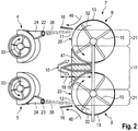
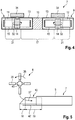
- FIGS. 1 to 6 1 An embodiment that in the FIGS. 1 to 6 1 , comprises a combine harvester 1 according to the invention, which is equipped with a threshing element 2 , a separating element 3 , two conveying devices 4 , 5 , a comminution element 6 and a discharge device 7 . Furthermore, the combine harvester 1 comprises a cutting unit 25 at its front end. By means of this cutting unit 25 , the combine harvester 1 is adapted to cut plants 40 which stand up on a field and then to guide them by means of an inclined conveyor 41 in the direction of the threshing member 2 . 2 by means of the Dreschorgans fruits are then separated or detached from the plant 40, so that from now on, the plants 40 are at least substantially divided in fruit and plant residues.
- a large part of the peeled fruits is derived directly through a concave 42 , starting from the threshing organ 2 downwards, while also forwarding a mixture of remaining fruits and plant residues in the direction of the separating member 3 .
- the latter is suitable for separating the remaining fruits, which were not directly discharged through the thresher basket 42 , from the plant residues, so that the fruits can be collected and the plant residues removed from the combine harvester 1 .
- the separating element 3 has in the example shown, via a straw walker 28 by means of which are screened by means of cyclic movements, the remaining fruits from plant debris, while the plant remains, in particular coarse plant residues, for example in the form of straw, substantially in the direction of a rear end of the combine harvester 1 be transported away.
- the relatively small fruits and fine plant remains are down through the Horden—ler 28 a return bottom 29 of the separating element 3 is passed , by means of which these components are first passed in the direction of the front end of the combine 1 . Then said components are fed to a screening stage, which is formed in the example shown by a top wire 30 and a bottom wire 31 .
- This screening stage cooperates with a blower 26 , by means of which fine plant residues, for example chaff arising during the grain harvest, are separated from the fruits to be harvested.
- An airflow caused by the blower 26 is in FIG. 1 illustrated by the arrows 27 shown there.
- the fruits finally obtained in this way are fed by means of a lifting device 43 to a grain tank 44 of the combine harvester 1 .
- the plant when the plant remains after their ejection from the combine harvester 1 remain on the ground and should not be included in the further and then continue to be used (for example, in livestock), for the purpose of easier decomposition of the plant remains and the subsequent taking place of the contained therein Nutrients through the soil, at least for the coarse plant residues first made a crushing.
- the already mentioned comminution element 6 is used, by means of which the coarse plant residues deposited on the tray shaker 28 at the rear are taken over and comminuted.
- the comminution element 6 can have a shaft 45 and blow bars 35 which are distributed laterally along the circumference of the shaft 45 and which, in the course of a rotation of the shaft 45 about its longitudinal axis (arrow 36 in FIG FIG. 5 ) break the plant remains downright.
- the fine plant residues, which are discharged from the combine harvester 1 starting from the screening stage, as a rule do not require such comminution and are consequently not supplied to the comminution organ 6 in the example shown.
- the plant residues are processed by means of the discharge device 7 .
- the latter comprises, in the example shown, two distributing devices 8 , 9 which are themselves in particular from the Figures 2 . 4 and 6 result.
- the distributing devices 8, 9 are each formed here by a radial distributor , which comprises a housing 13 in the form of a circular ring and a rotor 14 rotatably mounted inside the housing 13 .
- the rotor 14 which is rotationally driven by means of a drive 34 arranged above the housing 13 , is here combined with four blade elements 15 , which are suitable for detecting and accelerating plant residues entering the respective distribution device 8 , 9 , so that these are at the rear End of the combine harvester 1 and a back of the discharge 7 can be "thrown” away at an increased speed.
- This makes it possible to distribute the plant residues, starting from the comparatively narrow end of the combine harvester 1, to an area which extends over a significantly larger working width of the cutting unit 25 .
- the discharge device 7 takes over two separate crop flows 38, 39 of plant residues, namely, firstly , directly from the comminuting element 6 and, secondly, from the two conveying devices 4, 5 .
- the discharge device 7 comprises a subelement 10 , which is positioned centrally between the distributing devices 8 , 9 .
- the partial element 10 which has in the example shown a front wedge portion 18 and a subsequent constant portion 19 , serves to divide the originating from the crushing member 6 good flow 39 of the plant residues on the two distribution devices 8, 9 .
- the sub-element 10 extends in the direction of the comminution element 6 as, for example, based on FIG. 5 results.
- a partial stream of the crop residues 39 originating from the comminution organ 6 and separated by means of the subelement 10 in the direction of the left distribution devices 9 is shown in FIG FIG. 5 illustrated by an arrow 37 .
- the said wedge portion 18 of the sub-element 10 in the flow directions of the plant residues viewed clearly in front of the distribution devices 8, 9 is arranged and the sub-element 10 by the way by means of its constant section 19 to the distribution devices 8 , 9th extends.
- the conveyors 4 , 5 which are each formed in the example shown by a radial fan, in turn take over the relatively fine plant residues from the screening stage of the separating element. 3
- the conveyors 4 , 5 are often referred to as "chaffing fan", since the acquired from the screening stage plant residues in the Grain crops are formed in particular by chaff.
- the conveyors 4 , 5 are viewed in the flow direction of the plant residues upstream of the distributing devices 8 , 9 , so that the plant residues taken over by the conveyors 4 , 5 are first supplied to the discharge device 7 before they are discharged from the combine harvester 1 . This is especially true of the Figures 2 . 3 and 6 seen.
- the crop stream 38 which is fed to the discharge device 7 on the basis of the conveying devices 4 , 5 , enters the distribution devices 8 , 9 at entry points 11, 12 , which lie outside an effective range of the partial element 10 .
- the entry points 11 , 12 on the distributing devices 8 , 9 at least substantially prevents the product stream 39 originating from the comminution organ 6 from blocking the product stream 38 originating from the conveying devices 4 , 5 when entering the distributing devices 8 , 9 with special needs.
- the latter is particularly the case when the comparatively fine plant residues, which make up the good stream 38 , are introduced at one point into a respective distributor 8 , 9 , to which the housing 13 of the distributor 8 , 9 already to a large extent, possibly even completely , is filled with originating from the comminution organ 6 , coarse plant residues.
- the entry points 11 , 12 are each arranged in mutually remote edge regions 21 of the distribution device 8 , 9 , while the partial element 10 is arranged centrally between the distribution devices 8 , 9 .
- an area of action of the partial element 10 is limited within a central region 17 of the discharge device 7 , wherein the effect of the partial element 10 is that within the effective range, a large part of the plant residues originating from the comminution organ 6 are fed to the distribution devices 8 , 9 .
- the distributing devices 8 , 9 are also closed in their central region 17 by means of a bottom element 47 from below.
- the bottom element 47 advantageously extends to a front end of the partial element 10 , so that in particular the product flow 39 originating from the comminution element 6 is prevented from "passing" the distribution devices 8 , 9 seen in the vertical direction.
- the front end 20 of the distributing devices 8 , 9 facing the front end of the combine harvester 1 are designed to be fully open.
- the entry points 11 , 12 are in this case defined in particular by the fact that they represent those points to which the plant residues taken over by the conveyors 4, 5 impinge.
- the entry points 11 , 12 can thus be adjusted by means of a configuration of the conveyors 4 , 5 , wherein in particular a target direction of the conveyors 4 , 5 , in the direction of the plant residues are fed from the conveyors 4 , 5 of the discharge 7 , can be adjusted. In the example shown, this is done by means of guide channel stubs 24 , as will be explained separately below.
- the distributing devices 8 , 9 are in the example shown advantageously configured such that the rotors 14 in opposite directions in the in the Figures 2 and 6 By means of the arrows 32 shown there illustrated directions of rotation are driven. In this way, it is ensured that the fine plant residues, which originate from the conveying devices 4 , 5 and enter the distributing devices 8 , 9 through the entry points 11 , 12 , viewed in time from the coarse plant residues originating from the comminution organ 6 into the housing 13 the respective distribution device 8 , 9 enter.
- the conveyors are also 4 in the example shown, provided with guide channel 24 butts. 5
- This guide channel stub 24 , the outlet openings 22 , 23 of the conveyors 4 , 5 have, offer the possibility of imparting a flow direction to each of the conveyors 4 , 5 originating material flow 38 . In this way, the plant remains in a sense in the direction of the entry points 11 , 12 "targeted".
- the outlet openings 22 , 23 are arranged in edge regions of the conveying devices 4 , 5 remote from each other, so that the distances between the outlet openings 22 , 23 and the respective points of entry 11 , 12 assigned to them are as short as possible and, on the other hand, a flow direction is aligned as parallel as possible to a longitudinal axis of the combine harvester 1 .
- the conveying devices 4 , 5 are configured in the example shown in such a way that their fan motors according to the in FIGS FIG. 2 Arrows 33 rotate in opposite directions.
- the discharge device 7 of the combine harvester 1 is equipped in the example shown with two separation components 16 , one deposition component 16 being assigned to one of the distribution devices 8 , 9 in each case.
- the deposition components 16 are positioned such that they are arranged in the direction of rotation of a respective rotor 14 of a respective distribution device 8 , 9 in front of the respective entry point 11 , 12 .
- the separation members 16 serve to radially divert a generated by means of the distribution devices 8 , 9 tangential air flow. This is in FIG. 2 illustrated by the arrows 46 shown there.
- the separation of this tangential air flow is advantageous insofar as this air flow can then exert no disturbing influence on the plant residues originating from the conveying devices 4 , 5 .
Landscapes
- Life Sciences & Earth Sciences (AREA)
- Environmental Sciences (AREA)
- Combined Means For Separation Of Solids (AREA)
- Threshing Machine Elements (AREA)
Applications Claiming Priority (1)
| Application Number | Priority Date | Filing Date | Title |
|---|---|---|---|
| DE102018102594.7A DE102018102594A1 (de) | 2018-02-06 | 2018-02-06 | Mähdrescher |
Publications (2)
| Publication Number | Publication Date |
|---|---|
| EP3520596A1 true EP3520596A1 (fr) | 2019-08-07 |
| EP3520596B1 EP3520596B1 (fr) | 2021-05-26 |
Family
ID=64456790
Family Applications (1)
| Application Number | Title | Priority Date | Filing Date |
|---|---|---|---|
| EP18207943.4A Active EP3520596B1 (fr) | 2018-02-06 | 2018-11-23 | Moissonneuse-batteuse |
Country Status (2)
| Country | Link |
|---|---|
| EP (1) | EP3520596B1 (fr) |
| DE (1) | DE102018102594A1 (fr) |
Cited By (7)
| Publication number | Priority date | Publication date | Assignee | Title |
|---|---|---|---|---|
| US20210127587A1 (en) * | 2015-07-14 | 2021-05-06 | Dean Mayerle | Weed Seed Destruction with Replaceable Stator Components |
| US20210298235A1 (en) * | 2020-03-24 | 2021-09-30 | Claas Selbstfahrende Erntemaschinen Gmbh | Self-propelling combine and method for operating a self-propelling combine |
| US11666001B2 (en) | 2019-03-14 | 2023-06-06 | Tritana Intellectual Property Ltd. | Weed seed destruction |
| US12016271B2 (en) | 2020-03-12 | 2024-06-25 | Tritana Intellectual Property Ltd. | Weed seed destruction with improved wear characterisitics |
| US12295292B2 (en) | 2019-03-14 | 2025-05-13 | Tritana Intellectual Property Ltd. | Weed seed destruction |
| US12457940B2 (en) | 2021-07-30 | 2025-11-04 | Tritana Intellectual Property Ltd. | Weed seed destruction |
| US12604812B2 (en) | 2019-03-14 | 2026-04-21 | Tritana Intellectual Property Ltd. | Weed seed destruction on a combine harvester including a moveable guide wall for the chaff and weed seeds from the sieve |
Families Citing this family (1)
| Publication number | Priority date | Publication date | Assignee | Title |
|---|---|---|---|---|
| US12610886B2 (en) | 2019-03-14 | 2026-04-28 | Tritana Intellectual Property Ltd. | Weed seed destruction on a combine harvester including transferring grain from the grain loss sensor to the destructor |
Citations (5)
| Publication number | Priority date | Publication date | Assignee | Title |
|---|---|---|---|---|
| EP1269822A1 (fr) * | 2001-06-27 | 2003-01-02 | CLAAS Selbstfahrende Erntemaschinen GmbH | Moissonneuse-batteuse avec une soufflerie de décharge |
| DE102005056553A1 (de) * | 2005-11-25 | 2007-05-31 | Claas Selbstfahrende Erntemaschinen Gmbh | Verteileinrichtung für Gutstrom |
| EP2138025A1 (fr) * | 2008-06-25 | 2009-12-30 | CNH Belgium N.V. | Agencement de guide de récolte pour l'arrière d'une moissonneuse agricole |
| DE102009042002A1 (de) * | 2009-09-21 | 2011-03-24 | Claas Selbstfahrende Erntemaschinen Gmbh | Verfahren und Verteilen eines Gutstromes auf einem Feld sowie Häcksel- und Verteilvorrichtung |
| DE102013105836A1 (de) | 2013-06-06 | 2014-12-11 | Claas Selbstfahrende Erntemaschinen Gmbh | Mähdrescher |
-
2018
- 2018-02-06 DE DE102018102594.7A patent/DE102018102594A1/de not_active Withdrawn
- 2018-11-23 EP EP18207943.4A patent/EP3520596B1/fr active Active
Patent Citations (5)
| Publication number | Priority date | Publication date | Assignee | Title |
|---|---|---|---|---|
| EP1269822A1 (fr) * | 2001-06-27 | 2003-01-02 | CLAAS Selbstfahrende Erntemaschinen GmbH | Moissonneuse-batteuse avec une soufflerie de décharge |
| DE102005056553A1 (de) * | 2005-11-25 | 2007-05-31 | Claas Selbstfahrende Erntemaschinen Gmbh | Verteileinrichtung für Gutstrom |
| EP2138025A1 (fr) * | 2008-06-25 | 2009-12-30 | CNH Belgium N.V. | Agencement de guide de récolte pour l'arrière d'une moissonneuse agricole |
| DE102009042002A1 (de) * | 2009-09-21 | 2011-03-24 | Claas Selbstfahrende Erntemaschinen Gmbh | Verfahren und Verteilen eines Gutstromes auf einem Feld sowie Häcksel- und Verteilvorrichtung |
| DE102013105836A1 (de) | 2013-06-06 | 2014-12-11 | Claas Selbstfahrende Erntemaschinen Gmbh | Mähdrescher |
Cited By (21)
| Publication number | Priority date | Publication date | Assignee | Title |
|---|---|---|---|---|
| US20230180660A1 (en) * | 2015-07-14 | 2023-06-15 | Dean Mayerle | Weed seed destruction |
| US12389826B2 (en) * | 2015-07-14 | 2025-08-19 | Tritana Intellectual Property Ltd. | Combine harvester with weed seed destruction |
| US20210127585A1 (en) * | 2015-07-14 | 2021-05-06 | Dean Mayerle | Weed Seed Destruction Rotor Shape |
| US12599060B2 (en) | 2015-07-14 | 2026-04-14 | Tritana Intellectual Property Ltd. | Weed seed destruction |
| US11178817B2 (en) * | 2015-07-14 | 2021-11-23 | Tritana Intellectual Property Ltd. | Weed seed destruction drive transfer arrangement |
| US11202405B2 (en) * | 2015-07-14 | 2021-12-21 | Tritana Intellectual Property Ltd. | Weed seed destruction for a combine harvester with a transfer member across a rear edge of the combine sieve |
| US20220295704A1 (en) * | 2015-07-14 | 2022-09-22 | Tritana Intellectual Property Ltd. | Combine harvester with weed seed destruction |
| US11612101B2 (en) * | 2015-07-14 | 2023-03-28 | Tritana Intellectual Property Ltd. | Combine harvester with combined spreading of material from a straw chopper and a weed seed destructor |
| US20230157207A1 (en) * | 2015-07-14 | 2023-05-25 | Dean Mayerle | Weed seed destruction |
| US12477980B2 (en) | 2015-07-14 | 2025-11-25 | Tritana Intellectual Property Ltd. | Combine harvester with a guide between a weed seed destruction section and a straw spreading section |
| US20210127586A1 (en) * | 2015-07-14 | 2021-05-06 | Dean Mayerle | Weed Seed Destruction with Rotor and Stator Where the Discharge is Axially Spaced from the Inlet |
| US12029161B2 (en) | 2015-07-14 | 2024-07-09 | Tritana Intellectual Property Ltd. | Weed seed destruction rotor shape |
| US20210127587A1 (en) * | 2015-07-14 | 2021-05-06 | Dean Mayerle | Weed Seed Destruction with Replaceable Stator Components |
| US12108703B2 (en) | 2015-07-14 | 2024-10-08 | Tritana Intellectual Property Ltd. | Weed seed destruction with replaceable stator components |
| US12225845B2 (en) | 2015-07-14 | 2025-02-18 | Tritana Intellectual Property Ltd. | Weed seed destruction with rotor and stator where the discharge is axially spaced from the inlet |
| US12295292B2 (en) | 2019-03-14 | 2025-05-13 | Tritana Intellectual Property Ltd. | Weed seed destruction |
| US11666001B2 (en) | 2019-03-14 | 2023-06-06 | Tritana Intellectual Property Ltd. | Weed seed destruction |
| US12604812B2 (en) | 2019-03-14 | 2026-04-21 | Tritana Intellectual Property Ltd. | Weed seed destruction on a combine harvester including a moveable guide wall for the chaff and weed seeds from the sieve |
| US12016271B2 (en) | 2020-03-12 | 2024-06-25 | Tritana Intellectual Property Ltd. | Weed seed destruction with improved wear characterisitics |
| US20210298235A1 (en) * | 2020-03-24 | 2021-09-30 | Claas Selbstfahrende Erntemaschinen Gmbh | Self-propelling combine and method for operating a self-propelling combine |
| US12457940B2 (en) | 2021-07-30 | 2025-11-04 | Tritana Intellectual Property Ltd. | Weed seed destruction |
Also Published As
| Publication number | Publication date |
|---|---|
| DE102018102594A1 (de) | 2019-08-08 |
| EP3520596B1 (fr) | 2021-05-26 |
Similar Documents
| Publication | Publication Date | Title |
|---|---|---|
| EP3520596B1 (fr) | Moissonneuse-batteuse | |
| EP3662738B1 (fr) | Moissonneuse-batteuse automotrice | |
| EP1232683B1 (fr) | Eléments entraîneurs ef dispositif broyeur pour machine agricole | |
| EP2298061B1 (fr) | Procédé de répartition d'un flux de matière sur un champ et dispositif de hachage et de répartition | |
| DE2729033C2 (fr) | ||
| EP2286654B1 (fr) | Agencement de hachage et de répartition de résidus de produits de récolte pour une moissonneuse-batteuse | |
| DE3789232T2 (de) | Mähdrescher mit angebautem, drehbarem strohhäcksler. | |
| EP1897430B1 (fr) | Dispositif de hachage et de répartition | |
| DE10064356A1 (de) | Vorrichtung und Verfahren zur Erntegutförderung in landwirtschaftlichen Arbeitsmaschinen | |
| DE2462568A1 (de) | Dreschmaschine, insbesondere maehdrescher | |
| EP3662737B1 (fr) | Moissonneuse-batteuse automotrice | |
| DE10063550B4 (de) | Mähdrescher mit Häckseleinrichtung | |
| DE3122920C2 (fr) | ||
| EP0727135B1 (fr) | Moissonneuse-batteuse | |
| EP2232976B1 (fr) | Agencement de hachage et de répartition de résidus de produits de récolte pour une moissonneuse-batteuse | |
| DE3025380A1 (de) | Maehdrescher | |
| DE3148369A1 (de) | Axialfluss-maehdrescher mit kombiniertem haecksler-auswerfer | |
| WO2005041639A1 (fr) | Dispositif de hachage pour moissonneuse-batteuse | |
| EP1869969B1 (fr) | Système à hacher la paille pour une moissonneuse-batteuse | |
| EP4349183B1 (fr) | Machine de récolte de cucurbitacées | |
| DE3345919C2 (fr) | ||
| EP1820389B1 (fr) | Moissonneuse-batteuse avec zone de séparation multi-étagée | |
| BE1023629B1 (de) | Erntegutresteverteileinrichtung für einen Mähdrescher | |
| DE3824166C2 (de) | Verteilvorrichtung für Streugut | |
| AT129797B (de) | Verfahren zum Dreschen von Getreide, Zerreißen von Stroh, Trennen von Korn und Stroh und Reinigen von Korn in Axialdreschmaschinen oder in Axialdresch- und -strohzerreißmaschinen und Maschinen zur Ausführung dieses Verfahrens. |
Legal Events
| Date | Code | Title | Description |
|---|---|---|---|
| PUAI | Public reference made under article 153(3) epc to a published international application that has entered the european phase |
Free format text: ORIGINAL CODE: 0009012 |
|
| STAA | Information on the status of an ep patent application or granted ep patent |
Free format text: STATUS: THE APPLICATION HAS BEEN PUBLISHED |
|
| AK | Designated contracting states |
Kind code of ref document: A1 Designated state(s): AL AT BE BG CH CY CZ DE DK EE ES FI FR GB GR HR HU IE IS IT LI LT LU LV MC MK MT NL NO PL PT RO RS SE SI SK SM TR |
|
| AX | Request for extension of the european patent |
Extension state: BA ME |
|
| STAA | Information on the status of an ep patent application or granted ep patent |
Free format text: STATUS: REQUEST FOR EXAMINATION WAS MADE |
|
| 17P | Request for examination filed |
Effective date: 20200207 |
|
| RBV | Designated contracting states (corrected) |
Designated state(s): AL AT BE BG CH CY CZ DE DK EE ES FI FR GB GR HR HU IE IS IT LI LT LU LV MC MK MT NL NO PL PT RO RS SE SI SK SM TR |
|
| GRAP | Despatch of communication of intention to grant a patent |
Free format text: ORIGINAL CODE: EPIDOSNIGR1 |
|
| STAA | Information on the status of an ep patent application or granted ep patent |
Free format text: STATUS: GRANT OF PATENT IS INTENDED |
|
| INTG | Intention to grant announced |
Effective date: 20201214 |
|
| GRAS | Grant fee paid |
Free format text: ORIGINAL CODE: EPIDOSNIGR3 |
|
| GRAA | (expected) grant |
Free format text: ORIGINAL CODE: 0009210 |
|
| STAA | Information on the status of an ep patent application or granted ep patent |
Free format text: STATUS: THE PATENT HAS BEEN GRANTED |
|
| AK | Designated contracting states |
Kind code of ref document: B1 Designated state(s): AL AT BE BG CH CY CZ DE DK EE ES FI FR GB GR HR HU IE IS IT LI LT LU LV MC MK MT NL NO PL PT RO RS SE SI SK SM TR |
|
| REG | Reference to a national code |
Ref country code: GB Ref legal event code: FG4D Free format text: NOT ENGLISH |
|
| REG | Reference to a national code |
Ref country code: CH Ref legal event code: EP |
|
| REG | Reference to a national code |
Ref country code: DE Ref legal event code: R096 Ref document number: 502018005416 Country of ref document: DE |
|
| REG | Reference to a national code |
Ref country code: AT Ref legal event code: REF Ref document number: 1395283 Country of ref document: AT Kind code of ref document: T Effective date: 20210615 |
|
| REG | Reference to a national code |
Ref country code: IE Ref legal event code: FG4D Free format text: LANGUAGE OF EP DOCUMENT: GERMAN |
|
| REG | Reference to a national code |
Ref country code: LT Ref legal event code: MG9D |
|
| PG25 | Lapsed in a contracting state [announced via postgrant information from national office to epo] |
Ref country code: BG Free format text: LAPSE BECAUSE OF FAILURE TO SUBMIT A TRANSLATION OF THE DESCRIPTION OR TO PAY THE FEE WITHIN THE PRESCRIBED TIME-LIMIT Effective date: 20210826 Ref country code: FI Free format text: LAPSE BECAUSE OF FAILURE TO SUBMIT A TRANSLATION OF THE DESCRIPTION OR TO PAY THE FEE WITHIN THE PRESCRIBED TIME-LIMIT Effective date: 20210526 Ref country code: LT Free format text: LAPSE BECAUSE OF FAILURE TO SUBMIT A TRANSLATION OF THE DESCRIPTION OR TO PAY THE FEE WITHIN THE PRESCRIBED TIME-LIMIT Effective date: 20210526 Ref country code: HR Free format text: LAPSE BECAUSE OF FAILURE TO SUBMIT A TRANSLATION OF THE DESCRIPTION OR TO PAY THE FEE WITHIN THE PRESCRIBED TIME-LIMIT Effective date: 20210526 |
|
| REG | Reference to a national code |
Ref country code: NL Ref legal event code: MP Effective date: 20210526 |
|
| PG25 | Lapsed in a contracting state [announced via postgrant information from national office to epo] |
Ref country code: GR Free format text: LAPSE BECAUSE OF FAILURE TO SUBMIT A TRANSLATION OF THE DESCRIPTION OR TO PAY THE FEE WITHIN THE PRESCRIBED TIME-LIMIT Effective date: 20210827 Ref country code: IS Free format text: LAPSE BECAUSE OF FAILURE TO SUBMIT A TRANSLATION OF THE DESCRIPTION OR TO PAY THE FEE WITHIN THE PRESCRIBED TIME-LIMIT Effective date: 20210926 Ref country code: PT Free format text: LAPSE BECAUSE OF FAILURE TO SUBMIT A TRANSLATION OF THE DESCRIPTION OR TO PAY THE FEE WITHIN THE PRESCRIBED TIME-LIMIT Effective date: 20210927 Ref country code: NO Free format text: LAPSE BECAUSE OF FAILURE TO SUBMIT A TRANSLATION OF THE DESCRIPTION OR TO PAY THE FEE WITHIN THE PRESCRIBED TIME-LIMIT Effective date: 20210826 Ref country code: LV Free format text: LAPSE BECAUSE OF FAILURE TO SUBMIT A TRANSLATION OF THE DESCRIPTION OR TO PAY THE FEE WITHIN THE PRESCRIBED TIME-LIMIT Effective date: 20210526 Ref country code: PL Free format text: LAPSE BECAUSE OF FAILURE TO SUBMIT A TRANSLATION OF THE DESCRIPTION OR TO PAY THE FEE WITHIN THE PRESCRIBED TIME-LIMIT Effective date: 20210526 Ref country code: SE Free format text: LAPSE BECAUSE OF FAILURE TO SUBMIT A TRANSLATION OF THE DESCRIPTION OR TO PAY THE FEE WITHIN THE PRESCRIBED TIME-LIMIT Effective date: 20210526 Ref country code: RS Free format text: LAPSE BECAUSE OF FAILURE TO SUBMIT A TRANSLATION OF THE DESCRIPTION OR TO PAY THE FEE WITHIN THE PRESCRIBED TIME-LIMIT Effective date: 20210526 |
|
| PG25 | Lapsed in a contracting state [announced via postgrant information from national office to epo] |
Ref country code: NL Free format text: LAPSE BECAUSE OF FAILURE TO SUBMIT A TRANSLATION OF THE DESCRIPTION OR TO PAY THE FEE WITHIN THE PRESCRIBED TIME-LIMIT Effective date: 20210526 |
|
| PG25 | Lapsed in a contracting state [announced via postgrant information from national office to epo] |
Ref country code: EE Free format text: LAPSE BECAUSE OF FAILURE TO SUBMIT A TRANSLATION OF THE DESCRIPTION OR TO PAY THE FEE WITHIN THE PRESCRIBED TIME-LIMIT Effective date: 20210526 Ref country code: ES Free format text: LAPSE BECAUSE OF FAILURE TO SUBMIT A TRANSLATION OF THE DESCRIPTION OR TO PAY THE FEE WITHIN THE PRESCRIBED TIME-LIMIT Effective date: 20210526 Ref country code: SK Free format text: LAPSE BECAUSE OF FAILURE TO SUBMIT A TRANSLATION OF THE DESCRIPTION OR TO PAY THE FEE WITHIN THE PRESCRIBED TIME-LIMIT Effective date: 20210526 Ref country code: SM Free format text: LAPSE BECAUSE OF FAILURE TO SUBMIT A TRANSLATION OF THE DESCRIPTION OR TO PAY THE FEE WITHIN THE PRESCRIBED TIME-LIMIT Effective date: 20210526 Ref country code: DK Free format text: LAPSE BECAUSE OF FAILURE TO SUBMIT A TRANSLATION OF THE DESCRIPTION OR TO PAY THE FEE WITHIN THE PRESCRIBED TIME-LIMIT Effective date: 20210526 Ref country code: CZ Free format text: LAPSE BECAUSE OF FAILURE TO SUBMIT A TRANSLATION OF THE DESCRIPTION OR TO PAY THE FEE WITHIN THE PRESCRIBED TIME-LIMIT Effective date: 20210526 Ref country code: RO Free format text: LAPSE BECAUSE OF FAILURE TO SUBMIT A TRANSLATION OF THE DESCRIPTION OR TO PAY THE FEE WITHIN THE PRESCRIBED TIME-LIMIT Effective date: 20210526 |
|
| REG | Reference to a national code |
Ref country code: DE Ref legal event code: R097 Ref document number: 502018005416 Country of ref document: DE |
|
| PLBE | No opposition filed within time limit |
Free format text: ORIGINAL CODE: 0009261 |
|
| STAA | Information on the status of an ep patent application or granted ep patent |
Free format text: STATUS: NO OPPOSITION FILED WITHIN TIME LIMIT |
|
| 26N | No opposition filed |
Effective date: 20220301 |
|
| PG25 | Lapsed in a contracting state [announced via postgrant information from national office to epo] |
Ref country code: IS Free format text: LAPSE BECAUSE OF FAILURE TO SUBMIT A TRANSLATION OF THE DESCRIPTION OR TO PAY THE FEE WITHIN THE PRESCRIBED TIME-LIMIT Effective date: 20210926 Ref country code: AL Free format text: LAPSE BECAUSE OF FAILURE TO SUBMIT A TRANSLATION OF THE DESCRIPTION OR TO PAY THE FEE WITHIN THE PRESCRIBED TIME-LIMIT Effective date: 20210526 |
|
| PG25 | Lapsed in a contracting state [announced via postgrant information from national office to epo] |
Ref country code: MC Free format text: LAPSE BECAUSE OF FAILURE TO SUBMIT A TRANSLATION OF THE DESCRIPTION OR TO PAY THE FEE WITHIN THE PRESCRIBED TIME-LIMIT Effective date: 20210526 |
|
| REG | Reference to a national code |
Ref country code: CH Ref legal event code: PL |
|
| PG25 | Lapsed in a contracting state [announced via postgrant information from national office to epo] |
Ref country code: IT Free format text: LAPSE BECAUSE OF FAILURE TO SUBMIT A TRANSLATION OF THE DESCRIPTION OR TO PAY THE FEE WITHIN THE PRESCRIBED TIME-LIMIT Effective date: 20210526 Ref country code: LU Free format text: LAPSE BECAUSE OF NON-PAYMENT OF DUE FEES Effective date: 20211123 |
|
| PG25 | Lapsed in a contracting state [announced via postgrant information from national office to epo] |
Ref country code: IE Free format text: LAPSE BECAUSE OF NON-PAYMENT OF DUE FEES Effective date: 20211123 |
|
| PG25 | Lapsed in a contracting state [announced via postgrant information from national office to epo] |
Ref country code: FR Free format text: LAPSE BECAUSE OF NON-PAYMENT OF DUE FEES Effective date: 20211130 |
|
| P01 | Opt-out of the competence of the unified patent court (upc) registered |
Effective date: 20230516 |
|
| PG25 | Lapsed in a contracting state [announced via postgrant information from national office to epo] |
Ref country code: CY Free format text: LAPSE BECAUSE OF FAILURE TO SUBMIT A TRANSLATION OF THE DESCRIPTION OR TO PAY THE FEE WITHIN THE PRESCRIBED TIME-LIMIT Effective date: 20210526 |
|
| GBPC | Gb: european patent ceased through non-payment of renewal fee |
Effective date: 20221123 |
|
| PG25 | Lapsed in a contracting state [announced via postgrant information from national office to epo] |
Ref country code: LI Free format text: LAPSE BECAUSE OF NON-PAYMENT OF DUE FEES Effective date: 20220630 Ref country code: HU Free format text: LAPSE BECAUSE OF FAILURE TO SUBMIT A TRANSLATION OF THE DESCRIPTION OR TO PAY THE FEE WITHIN THE PRESCRIBED TIME-LIMIT; INVALID AB INITIO Effective date: 20181123 Ref country code: CH Free format text: LAPSE BECAUSE OF NON-PAYMENT OF DUE FEES Effective date: 20220630 |
|
| PG25 | Lapsed in a contracting state [announced via postgrant information from national office to epo] |
Ref country code: GB Free format text: LAPSE BECAUSE OF NON-PAYMENT OF DUE FEES Effective date: 20221123 |
|
| PG25 | Lapsed in a contracting state [announced via postgrant information from national office to epo] |
Ref country code: MK Free format text: LAPSE BECAUSE OF FAILURE TO SUBMIT A TRANSLATION OF THE DESCRIPTION OR TO PAY THE FEE WITHIN THE PRESCRIBED TIME-LIMIT Effective date: 20210526 |
|
| PG25 | Lapsed in a contracting state [announced via postgrant information from national office to epo] |
Ref country code: TR Free format text: LAPSE BECAUSE OF FAILURE TO SUBMIT A TRANSLATION OF THE DESCRIPTION OR TO PAY THE FEE WITHIN THE PRESCRIBED TIME-LIMIT Effective date: 20210526 |
|
| PG25 | Lapsed in a contracting state [announced via postgrant information from national office to epo] |
Ref country code: MT Free format text: LAPSE BECAUSE OF FAILURE TO SUBMIT A TRANSLATION OF THE DESCRIPTION OR TO PAY THE FEE WITHIN THE PRESCRIBED TIME-LIMIT Effective date: 20210526 |
|
| REG | Reference to a national code |
Ref country code: AT Ref legal event code: MM01 Ref document number: 1395283 Country of ref document: AT Kind code of ref document: T Effective date: 20231123 |
|
| PG25 | Lapsed in a contracting state [announced via postgrant information from national office to epo] |
Ref country code: AT Free format text: LAPSE BECAUSE OF NON-PAYMENT OF DUE FEES Effective date: 20231123 |
|
| PG25 | Lapsed in a contracting state [announced via postgrant information from national office to epo] |
Ref country code: AT Free format text: LAPSE BECAUSE OF NON-PAYMENT OF DUE FEES Effective date: 20231123 |
|
| PGFP | Annual fee paid to national office [announced via postgrant information from national office to epo] |
Ref country code: DE Payment date: 20251119 Year of fee payment: 8 |
|
| PGFP | Annual fee paid to national office [announced via postgrant information from national office to epo] |
Ref country code: BE Payment date: 20251119 Year of fee payment: 8 |
|
| PGFP | Annual fee paid to national office [announced via postgrant information from national office to epo] |
Ref country code: AT Payment date: 20260410 Year of fee payment: 5 |