EP3520654A1 - Support pour tablette en fil metallique pour points de vente, pour supporter des separateurs, des balconettes, des barres à led - Google Patents
Support pour tablette en fil metallique pour points de vente, pour supporter des separateurs, des balconettes, des barres à led Download PDFInfo
- Publication number
- EP3520654A1 EP3520654A1 EP19153592.1A EP19153592A EP3520654A1 EP 3520654 A1 EP3520654 A1 EP 3520654A1 EP 19153592 A EP19153592 A EP 19153592A EP 3520654 A1 EP3520654 A1 EP 3520654A1
- Authority
- EP
- European Patent Office
- Prior art keywords
- support
- shelf
- stiffener
- wire
- dividers
- Prior art date
- Legal status (The legal status is an assumption and is not a legal conclusion. Google has not performed a legal analysis and makes no representation as to the accuracy of the status listed.)
- Granted
Links
Images


Classifications
-
- A—HUMAN NECESSITIES
- A47—FURNITURE; DOMESTIC ARTICLES OR APPLIANCES; COFFEE MILLS; SPICE MILLS; SUCTION CLEANERS IN GENERAL
- A47F—SPECIAL FURNITURE, FITTINGS, OR ACCESSORIES FOR SHOPS, STOREHOUSES, BARS, RESTAURANTS OR THE LIKE; PAYING COUNTERS
- A47F5/00—Show stands, hangers, or shelves characterised by their constructional features
- A47F5/0018—Display racks with shelves or receptables
- A47F5/0025—Display racks with shelves or receptables having separate display containers or trays on shelves or on racks
-
- A—HUMAN NECESSITIES
- A47—FURNITURE; DOMESTIC ARTICLES OR APPLIANCES; COFFEE MILLS; SPICE MILLS; SUCTION CLEANERS IN GENERAL
- A47F—SPECIAL FURNITURE, FITTINGS, OR ACCESSORIES FOR SHOPS, STOREHOUSES, BARS, RESTAURANTS OR THE LIKE; PAYING COUNTERS
- A47F11/00—Arrangements in shop windows, shop floors or show cases
- A47F11/06—Means for bringing about special optical effects
- A47F11/10—Arrangements of light sources
-
- A—HUMAN NECESSITIES
- A47—FURNITURE; DOMESTIC ARTICLES OR APPLIANCES; COFFEE MILLS; SPICE MILLS; SUCTION CLEANERS IN GENERAL
- A47F—SPECIAL FURNITURE, FITTINGS, OR ACCESSORIES FOR SHOPS, STOREHOUSES, BARS, RESTAURANTS OR THE LIKE; PAYING COUNTERS
- A47F5/00—Show stands, hangers, or shelves characterised by their constructional features
- A47F5/0043—Show shelves
- A47F5/005—Partitions therefore
- A47F5/0056—Partitions therefore made of tubes or wire
-
- A—HUMAN NECESSITIES
- A47—FURNITURE; DOMESTIC ARTICLES OR APPLIANCES; COFFEE MILLS; SPICE MILLS; SUCTION CLEANERS IN GENERAL
- A47F—SPECIAL FURNITURE, FITTINGS, OR ACCESSORIES FOR SHOPS, STOREHOUSES, BARS, RESTAURANTS OR THE LIKE; PAYING COUNTERS
- A47F5/00—Show stands, hangers, or shelves characterised by their constructional features
- A47F5/0043—Show shelves
- A47F5/0068—Shelf extensions, e.g. fixed on price rail
-
- A—HUMAN NECESSITIES
- A47—FURNITURE; DOMESTIC ARTICLES OR APPLIANCES; COFFEE MILLS; SPICE MILLS; SUCTION CLEANERS IN GENERAL
- A47B—TABLES; DESKS; OFFICE FURNITURE; CABINETS; DRAWERS; GENERAL DETAILS OF FURNITURE
- A47B2220/00—General furniture construction, e.g. fittings
- A47B2220/0075—Lighting
- A47B2220/0077—Lighting for furniture, e.g. cupboards and racks
-
- F—MECHANICAL ENGINEERING; LIGHTING; HEATING; WEAPONS; BLASTING
- F21—LIGHTING
- F21V—FUNCTIONAL FEATURES OR DETAILS OF LIGHTING DEVICES OR SYSTEMS THEREOF; STRUCTURAL COMBINATIONS OF LIGHTING DEVICES WITH OTHER ARTICLES, NOT OTHERWISE PROVIDED FOR
- F21V33/00—Structural combinations of lighting devices with other articles, not otherwise provided for
- F21V33/0004—Personal or domestic articles
- F21V33/0012—Furniture
Definitions
- the present invention relates to the technical field of shopfitting for large points of sale, and in particular to an accessory for the shelving for displaying goods. More particularly, the invention relates to a support for accessories (fronts, dividers, LED bars) used in connection with wire shelves.
- Such shelving is well-known in the art; essentially two kinds of shelving are in use, a first kind supporting wire shelves and a second kind supporting metal sheet shelves.
- the first kind of shelf is made of metal wires soldered to each other to form a net capable of supporting goods.
- An example of such shelves is e.g. described in DE102005020253 of Wanzl Metallwarenfabrik KG.
- the second kind of shelf is produced through bending and soldering metal sheets, as described e.g. in US2005593A of LUXE METAL FURNITURE COMPANY.
- EP2695547A1 in the name of HMY Group describes an assembly for a shelving, comprising at least a shelf for displaying goods, a lighting device and a support element in the form of a clip, configured to support said lighting device and to be mounted under said shelf, wherein said support element comprises at least a guiding member, and said lighting element comprises at least a complementary guiding member configured to be rotatable with respect to said at least one guiding member, so that the tilting of said lighting device can be adjusted between two extreme positions defined by at least a stopping member of said support element.
- the support element described in this document can be coupled to a metal sheet shelf only, of the kind described in US2005593A .
- EP3017724 di Pos Tuning Udo Vosshenrich GMBH & CO KG describes a different lighting system, wherein at least a luminous means is placed in front of a goods package, and lights at least the goods lower portion. Differently from the previous two documents, the light it directed upwards.
- wire or metal sheet shelves through wire dividers is also known in the art.
- Such dividers occupy the whole short side of said shelves, so as to facilitate the filling of the shelf, especially when goods are of small dimensions with respect to the dimensions of the shelf itself.
- a device for partitioning a shelf is e.g. described in US9326604 of LogiQuip LLC.
- Another accessory is a front to prevent packages from falling from the shelf to the ground; such fronts are used especially when packages are particularly small or light, or when the shelf is tilted toward consumers.
- dividers and fronts that can be applied on the two different kind of shelves are different, which is a problem both for the manufacturer of shelves/accessories and for the point of sale itself, in that both are obliged to produce and stock dividers and fronts for the two different kinds of shelf.
- a second drawback comes from the fact that today point of sale shelving is frequently electrified in order to provide shelves with LED bars for lighting. Such bars are typically fixed to shelves and are a further encumbrance. Up to today the presence of LED bars and dividers/fronts was mutually exclusive.
- Aim of the present invention is providing an accessory allowing to use the same dividers and fronts on both kinds of metal sheet and wire shelves, practical to fix and remove, even in the presence of LED bars for lighting said shelves.
- the solution lies in a support, preferably made of plastics, which is fixed to wire shelves, allowing to use the same wire dividers and fronts used on metal sheet shelves.
- the first advantage of the present invention is the removal of an item code both for the manufacturer and the point of sale, which allows on one hand to reduce the number of stocked item codes, and on the other hand not to be deprived of the specific kind of divider/front needed at that very moment.
- the second advantage of the present invention is the possibility to use the same support both when the shelves are lighted by a LED bar and when they are free from LED bars, in this case, too, reducing the number of stocked components.
- a third advantage is that, using the support according to the present invention, when other dividers/fronts or even LED bars must be added to a shelf, the shelf itself need not be dismantled.
- a fourth advantage of the present invention is the limited aesthetical impact of the support according to the present invention, in particular when it is made of transparent plastics.
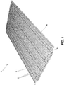
- Figure 1 shows a typical wire shelf.
- Said shelf comprises a plurality of generally equidistant metal wires 2, soldered to at least one stiffener 3 perpendicular to said wires.
- Said stiffeners 3 are flat metal sheet portions, some centimetres high.
- two further metal wires 4 and 5 are soldered to the two anterior and posterior ends. These two wires 4, 5 do not contribute to shelf load-carrying capacity, but improve its safety of use, protecting the protruding ends of metal wires.
- Figure 2 shows a metal sheet shelf 10 provided with a plurality of dividers 6 and a front 7.
- said dividers 6 and front 7 are identical, and are made of soldered metal wires.
- dividers 6 and fronts 7 are provided with feet 12 (not visible in Figure 2 ) at least at their ends, and optionally with a central foot, which are inserted into suitable holes 11 provided in the shelf itself.
- the metal sheet at the ends of shelf 10 is C-bended, as visible in the detail shown in Figure 2A .
- Said hole 11 is placed above a corresponding hole 11A provided in the lower portion of the C-fold.
- Said foot 12 of the divider 6 is inserted in both holes 11 and 11 A so as to confer stability to the assembly. It is worthwhile noting that the C-fold in the metal sheet is provided both on the anterior and the posterior side of shelf 10.
- the divider 6 is provided with a long and a short foot; the long foot having a length suitable for insertion into both holes 11, 11A, while the short foot being of a length suitable for insertion into the hole 11 only. In this way, a sufficient stability is obtained at the same time with an easier assembling.
- Figures 3A and 3B show a wire shelf provided with dividers 6, fronts 7, a LED bar 8 and a plurality of supports 9 ( Figure 3A ) and supports 59 ( Figure 3B ) according to the present invention, which are meant to support the dividers 6, the front 7 and an optional LED bar 8.
- Supports 9, 59 according to the present invention are mounted on stiffeners 3 through a snapping elastic coupling end, by exerting a light pressure of said support against said stiffener.
- the distance between stiffener 3 and the anterior 4 or posterior wire 5 is slightly shorter than the length of the support 9 (side 16 of the support).
- supports 9, 59 are inserted in the interspace between two adjacent wires 2 forming the supporting surface of the shelf, while they are snap-coupled to the transversal stiffener 3, to which wires 2 are soldered. Thanks to the fact that the distance between the stiffener 3 and the anterior and posterior finishing wire 4 and 5 parallel to said stiffener is shorter that the length of said support 9, 59 in the direction of said distance, when fitted in on the stiffener 3, supports 5, 59 are efficiently held in place against an accidental removal. In fact, the anterior wire 4 or the posterior wire 5 hinders the translation of the supports 5, 59 in the direction of removal from stiffener 3, so forming a limiter of disengagement of said supports.
- support 9, 59 is provided with a recess 15 allowing to house a LED bar 8, preferably in the form of a window closed on all peripheral sides, and through which said LED bar passes in the direction of its longitudinal axis.
- FIG. 4 shows a first embodiment of the support 9 according to the present invention.
- Said support is preferably made of plastics, preferably transparent plastics, so as to have a minimal aesthetical impact, even when the metal wire of the shelf is coloured.
- Said support 9 has essentially a rectangular shape, with two sides, top side 16 and bottom side 17, parallel to shelf 1; and two lateral sides 18 and 19, perpendicular to shelf 1.
- said hole 14 In the top side 16 of support 9 there is provided said hole 14 adjacent and perpendicular to the side 18 of the support itself, which houses the feet 12 of dividers 6 and fronts 7. Said hole 14 must have a diameter suitable for housing feet 12; as the diameter of their metal wire is about 5.5 mm, the hole 14 has a corresponding dimension, with the minimal play required for easily fixing said feet 12. Indicatively, the diameter of the hole 14 is about 6.2 mm.
- the width of support 9 must be overall such that said support 9 can be placed between two adjacent metal wires 2, which together with other wires 2 form a supporting shelf 1.
- the light between two consecutive metal wires 2 is 10 mm.
- the width of said support 9 is about 9 mm.
- One side 19 of support 9 is meant to mechanically snap-fit on a stiffener 3, and therefore is provided with two extensions 20, 21 protruding beyond said side 19; said extensions being a top extension 20 and a lower extension 21. Together, said two extensions 20 and 21 and the side 19 overall have a C-shape, and the distance of said extensions in the longitudinal direction of side 19 is commeasured to the length of the metal sheet forming said stiffener 3, to which said support must be coupled.
- the support 9 is fixed through said two extensions 20 and 21 to the top and bottom ends of the stiffener 3, thanks to the presence of two grooves, a top groove 22 and a bottom groove 23 provided in said extensions, respectively.
- the side 19 is placed rearward with respect to the position of the two grooves 20 and 21, in order to ensure to the support 9 the sufficient elasticity to snap-fit it on the stiffener 3.
- the support 9 When fixed, the support 9 is rigidly fitted in against stiffener 3 thanks to the fitting in of said two grooves 22 and 23, respectively, on the top and bottom ends of the stiffener itself, and to the leaning of the impact step 26 provided in the connecting zone of the lower extension 21 to the side 19 against the vertical wall of the stiffener 3 itself.
- the top extension 20 is provided in the form of a hook which delimits a groove having a given depth, while the lower extension 21 ends with a tooth having a transversal triangular section, so as to form a tilted taper surface which, when thrusting the support 9 against stiffener 3, cooperates with its lower longitudinal edge, contributing to the deformation in the direction of temporary stretching of the two extensions, and of overcoming said lower longitudinal edge of the stiffener 3 by said tooth, and therefore allowing the snap-fitting of said lower longitudinal edge into the groove 23.
- said support 9 is provided with a recess 15 meant to house a LED bar 8.
- the dimensions of said recess 15 are such that different kinds of LED bars 8 can be comfortably housed. Nonetheless, at the same time, the structure of the support must remain suitably rigid to maintain its mechanical features supporting dividers 6 and fronts 7.
- said recess is provided in the form of a window closed or closable on all its sides, so as to hold a LED bar, surrounding it completely.
- LED bars are optional, and potentially LED bars can be added at a later stage.
- the recess or window of supports 9 is openable, thanks to a locking mechanism 17, in particular in correspondence of the bottom side of supports.
- a locking mechanism 17 in particular in correspondence of the bottom side of supports.
- the locking mechanism 17 is composed by a segment of the lower side of the support, coinciding with said recess or window housing a LED bar. Said lower side segment is connected at an end of support 9 through a hinge 24 allowing the oscillation in the direction of opening and closing in the form of a compass of said side of the recess, without breakage issues due to an action of elastic bending of the material, based on the intrinsic elasticity only of the material, which on the long run might lead to mechanical stress and breakage.
- the opposed end of the oscillating side segment forming part of the locking mechanism 17 is provided in its turn a with a coupling snap-fit end, which end comprises a tooth mounted on an elastically flexible wing 117, which wing 117 overlaps through strain on a coupling wall or rib 217 of support 9, which is substantially parallel to said wing 117, said wing and said rib being overall provided with a coupling tooth 317 and a coupling seat 417 of said coupling tooth.
- said tooth 317 and said seat 417 are strained in engagement by the elastic force of said wing 117.
- the end of the oscillating side segment is provided with a stopping tab 25 to exert a disengaging force of the oscillating segment from the body of the support.
- the hinge 24 is made of one piece and of the same material of the support, and is a so-called film hinge, obtained from a thinning of the material between the oscillating lower segment and the remaining portion of said lower side of the support.
- the end of the oscillating segment bearing the elastic wing 117 protrudes beyond said elastic wing, and in the bottom and laterally overlaps on both sides on the body of the support, i.e. to the lower side of the coupling rib 217 with which wing 117 cooperates.
- the oscillating lower side segment is provided with a cradle shape 517 on its side toward the inside of said recess, e.g. made of three angulated walls and positioned so as to be tangent to a circumference or a curved line.
- closed locking mechanism 17 confers further mechanical rigidity to the support 9.
- said support 9 is a single piece with a resealable closing system.
- said support 59 comprises two distinct portions made of two different materials.
- said support 59 is identical to said support 9, even dimensionally: the difference lies in the configuration of the recess or window housing the LED bar.
- said recess or window is provided with a distinct removable portion in the shape of a cradle, which is fixable through snap-fitting to a lower side of support 59.
- said cradle is made of a metal wire having a pre-set elasticity
- the locking mechanism 29 is made of the ends of said cradle.
- said locking mechanism 29 is provided with a double U shape
- the wire of the locking mechanism 29 is suitably bent to form two parallel U-shaped segments, wherein the ends of the corresponding arms of U are connected to each other, so forming two coupling crosspieces, housed in two coupling seats 27 and 28, respectively.
- the two U-shaped segments are meant to house a LED bar 8.
- said connecting crosspieces of said two U-shaped segments hook to said support 59 through seats 27, 28, thanks to the controlled deformation of the wire 29 itself, which must be elastically compressed to draw near the terminal ends of the two U-shaped segments, so as to pass beyond the delimiting walls of seats 27, 28, and to go back to its initial dimension once inserted into its seats. Therefore, to separate the cradle 29 from the support 59, a new elastic compression must be exerted, drawing near the two top ends of the two U-shaped segments, so as to emerge from the seats and extract said cradle.
- a support 59 can be mounted without the locking mechanism 29 in order to support dividers 6 and fronts 7, while said locking mechanism 29 can be added at a later stage, only when a LED bar 8 must be added.
- Figure 6 shows a lateral view of the support 59 hooked to a stiffener 3 of a metal shelf 1.
- the C-shape of the hooking mechanism can be appreciated, said C comprising the top extension 20, the vertical side 19 and the bottom extension 21.
- a groove 22 In the extension 20 there is provided a groove 22, while in the extension 21 there are provided a groove 23 and an impact step 26.
- Figure 6 shows that said stiffener 3 sits into place against said impact step 26, but keeps a distance from the side 19 of the support, so that the support 59 is provided with the elasticity needed to allow to easily snap/remove said support 59 on the stiffener 3. It is apparent that the support 9 works in the same way, too, the difference between support 9 and support 59 lying only in the way in which said LED bar 8 is housed and supported by two different supports.
- Figures 7 and 8 show a plurality of dividers 6, 86 and fronts 7, 87, normally produced by manufacturers and commonly used in points of sale. Comparing these two Figures, the variety of kinds and dimensions of dividers and fronts can be appreciated. All the kinds of dividers and fronts shown in the Figures 7 and 8 are mountable on wire shelves thanks to the use of supports 5, 59 according to the present invention, suitably positioned with respect to the shelf consisting of wires 2 and correspondingly to the coupling lower extensions of the front and dividers.
- Figures 7 and 8 also show a metal sheet shelf 80 and a wire shelf 88 having a semi-circular shape, which are generally used for the end portions of sale shelving.
- the stiffener 83 of the semi-circular shelf is provided with the same dimensions (height and thickness) of the stiffener 3 of rectangular shelves, while the width of supports 9, 59 is sufficiently small, with respect to the radius of the circumference of the semi-circular shelf 88, to allow the hooking mechanism to work in the same way as it works on the rectangular shelf having a linear stiffener.
- the assembling method according to the present invention comprises the following steps:
- step d can be performed at a later stage, after months or even years, when the shelving must be lighted through the installation of new LED bars 8.
- supports 5, 59 can support dividers 6/fronts 7 and LED bars 8 in a totally independent way: that is, each support 9, 59 can support a divider 6/front 7 only, a LED bar 8 only, a divider 6/front 7 and a LED bar 8 at the same time. Consequently, the steps c and d of the assembling method can be performed in a way totally independent from each other, in the order c d or in the order d c in subsequent times, even very distant from each other.
- said support 59 can be initially mounted without its removable locking mechanism 29, which can be mounted at a later stage only, when it is decided to add at least one LED bar 8 to wire shelf 1.
- Said LED bar 8 can be removed by the support 9, 59 at any moment, e.g. when the shelf does not need lighting or because it is out of order. This advantageously does not require the dismantling of the shelf itself.
Landscapes
- Assembled Shelves (AREA)
- Freezers Or Refrigerated Showcases (AREA)
- Display Racks (AREA)
Priority Applications (1)
| Application Number | Priority Date | Filing Date | Title |
|---|---|---|---|
| PL19153592T PL3520654T3 (pl) | 2018-01-31 | 2019-01-24 | Połączenie wspornika z jedną półką |
Applications Claiming Priority (1)
| Application Number | Priority Date | Filing Date | Title |
|---|---|---|---|
| IT201800002267A IT201800002267A1 (it) | 2018-01-31 | 2018-01-31 | Supporto per piani di scaffalature in filo metallico per punti vendita, per il supporto di divisori, frontalini, barre a led |
Publications (2)
| Publication Number | Publication Date |
|---|---|
| EP3520654A1 true EP3520654A1 (fr) | 2019-08-07 |
| EP3520654B1 EP3520654B1 (fr) | 2021-11-17 |
Family
ID=61952920
Family Applications (1)
| Application Number | Title | Priority Date | Filing Date |
|---|---|---|---|
| EP19153592.1A Active EP3520654B1 (fr) | 2018-01-31 | 2019-01-24 | Combinaison d'un support avec une étagère |
Country Status (4)
| Country | Link |
|---|---|
| EP (1) | EP3520654B1 (fr) |
| ES (1) | ES2900631T3 (fr) |
| IT (1) | IT201800002267A1 (fr) |
| PL (1) | PL3520654T3 (fr) |
Citations (4)
| Publication number | Priority date | Publication date | Assignee | Title |
|---|---|---|---|---|
| WO2001025577A2 (fr) * | 1999-10-01 | 2001-04-12 | Burke Gibson Inc. | Support de dispositif porte-affichage |
| EP2695547A1 (fr) * | 2012-08-07 | 2014-02-12 | HMY Group | système d'assemblage pour étagère, comprenant un support présentant des articles, un système d'éclairage et un élement de montage |
| US20160091177A1 (en) * | 2014-09-29 | 2016-03-31 | Pascal-Simon Houle | Lighting support for mounting a light source onto a shelf |
| EP3017724A1 (fr) * | 2014-11-07 | 2016-05-11 | POS TUNING Udo Voßhenrich GmbH & Co. KG | Dispositif de presentation de marchandises |
-
2018
- 2018-01-31 IT IT201800002267A patent/IT201800002267A1/it unknown
-
2019
- 2019-01-24 EP EP19153592.1A patent/EP3520654B1/fr active Active
- 2019-01-24 PL PL19153592T patent/PL3520654T3/pl unknown
- 2019-01-24 ES ES19153592T patent/ES2900631T3/es active Active
Patent Citations (4)
| Publication number | Priority date | Publication date | Assignee | Title |
|---|---|---|---|---|
| WO2001025577A2 (fr) * | 1999-10-01 | 2001-04-12 | Burke Gibson Inc. | Support de dispositif porte-affichage |
| EP2695547A1 (fr) * | 2012-08-07 | 2014-02-12 | HMY Group | système d'assemblage pour étagère, comprenant un support présentant des articles, un système d'éclairage et un élement de montage |
| US20160091177A1 (en) * | 2014-09-29 | 2016-03-31 | Pascal-Simon Houle | Lighting support for mounting a light source onto a shelf |
| EP3017724A1 (fr) * | 2014-11-07 | 2016-05-11 | POS TUNING Udo Voßhenrich GmbH & Co. KG | Dispositif de presentation de marchandises |
Also Published As
| Publication number | Publication date |
|---|---|
| EP3520654B1 (fr) | 2021-11-17 |
| ES2900631T3 (es) | 2022-03-17 |
| PL3520654T3 (pl) | 2022-02-07 |
| IT201800002267A1 (it) | 2019-07-31 |
Similar Documents
| Publication | Publication Date | Title |
|---|---|---|
| US9754515B2 (en) | Support for communication elements in points of sale of products | |
| US10159340B2 (en) | Shelving support bracket assembly | |
| US6491173B1 (en) | Wire basket system | |
| RU2341169C2 (ru) | Устройство для управления расположением товара | |
| CA2414335C (fr) | Rayonnage-presentoir de produits | |
| US12262815B2 (en) | Hang standard and storage system including the hang standard | |
| US9596948B1 (en) | Free-standing slatwall | |
| US8596443B2 (en) | Goods feeding system for receiving and presenting goods | |
| US20100163501A1 (en) | Convertible Card Row | |
| US7712616B2 (en) | Double sided peg hook strips | |
| CN109843393A (zh) | 用于锻炼器械的管形架外凸横档 | |
| US7278617B2 (en) | Display hook and assembly having reduced drag | |
| EP1585407B1 (fr) | Systeme pour une suspension amovible d'etageres, de tiroirs ou analogues | |
| EP3520654B1 (fr) | Combinaison d'un support avec une étagère | |
| DK2473079T3 (en) | SEAT ELEMENT | |
| US6443545B1 (en) | Drawer construction | |
| US6581314B2 (en) | Label holder with selectively attachable sign holder | |
| US8783642B2 (en) | Method and object for fastening of posters | |
| KR200441200Y1 (ko) | 쇼케이스용 선반의 가격표 부착장치 | |
| US20100116956A1 (en) | Support Hooks for Use with Pegboards | |
| US2985315A (en) | Article display board | |
| EP2695547A1 (fr) | système d'assemblage pour étagère, comprenant un support présentant des articles, un système d'éclairage et un élement de montage | |
| KR102627286B1 (ko) | 상품 진열대 걸이 | |
| RU2745033C2 (ru) | Усиленные полки для металлических стеллажей, имеющие отверстия для пропускания и поддержания электрической проводки, и усовершенствованный способ сборки таких полок | |
| KR100577863B1 (ko) | 티슈 가이드 장치 |
Legal Events
| Date | Code | Title | Description |
|---|---|---|---|
| PUAI | Public reference made under article 153(3) epc to a published international application that has entered the european phase |
Free format text: ORIGINAL CODE: 0009012 |
|
| STAA | Information on the status of an ep patent application or granted ep patent |
Free format text: STATUS: THE APPLICATION HAS BEEN PUBLISHED |
|
| AK | Designated contracting states |
Kind code of ref document: A1 Designated state(s): AL AT BE BG CH CY CZ DE DK EE ES FI FR GB GR HR HU IE IS IT LI LT LU LV MC MK MT NL NO PL PT RO RS SE SI SK SM TR |
|
| AX | Request for extension of the european patent |
Extension state: BA ME |
|
| STAA | Information on the status of an ep patent application or granted ep patent |
Free format text: STATUS: REQUEST FOR EXAMINATION WAS MADE |
|
| 17P | Request for examination filed |
Effective date: 20190830 |
|
| RBV | Designated contracting states (corrected) |
Designated state(s): AL AT BE BG CH CY CZ DE DK EE ES FI FR GB GR HR HU IE IS IT LI LT LU LV MC MK MT NL NO PL PT RO RS SE SI SK SM TR |
|
| STAA | Information on the status of an ep patent application or granted ep patent |
Free format text: STATUS: EXAMINATION IS IN PROGRESS |
|
| 17Q | First examination report despatched |
Effective date: 20210129 |
|
| RAP1 | Party data changed (applicant data changed or rights of an application transferred) |
Owner name: IMOLA RETAIL SOLUTIONS S.R.L. |
|
| GRAP | Despatch of communication of intention to grant a patent |
Free format text: ORIGINAL CODE: EPIDOSNIGR1 |
|
| STAA | Information on the status of an ep patent application or granted ep patent |
Free format text: STATUS: GRANT OF PATENT IS INTENDED |
|
| GRAS | Grant fee paid |
Free format text: ORIGINAL CODE: EPIDOSNIGR3 |
|
| INTG | Intention to grant announced |
Effective date: 20210924 |
|
| GRAA | (expected) grant |
Free format text: ORIGINAL CODE: 0009210 |
|
| STAA | Information on the status of an ep patent application or granted ep patent |
Free format text: STATUS: THE PATENT HAS BEEN GRANTED |
|
| AK | Designated contracting states |
Kind code of ref document: B1 Designated state(s): AL AT BE BG CH CY CZ DE DK EE ES FI FR GB GR HR HU IE IS IT LI LT LU LV MC MK MT NL NO PL PT RO RS SE SI SK SM TR |
|
| REG | Reference to a national code |
Ref country code: GB Ref legal event code: FG4D |
|
| RIN1 | Information on inventor provided before grant (corrected) |
Inventor name: PASSANTI, ANDREA |
|
| REG | Reference to a national code |
Ref country code: IE Ref legal event code: FG4D |
|
| REG | Reference to a national code |
Ref country code: DE Ref legal event code: R096 Ref document number: 602019009238 Country of ref document: DE |
|
| REG | Reference to a national code |
Ref country code: AT Ref legal event code: REF Ref document number: 1447353 Country of ref document: AT Kind code of ref document: T Effective date: 20211215 |
|
| REG | Reference to a national code |
Ref country code: SE Ref legal event code: TRGR |
|
| REG | Reference to a national code |
Ref country code: LT Ref legal event code: MG9D |
|
| REG | Reference to a national code |
Ref country code: ES Ref legal event code: FG2A Ref document number: 2900631 Country of ref document: ES Kind code of ref document: T3 Effective date: 20220317 |
|
| REG | Reference to a national code |
Ref country code: NL Ref legal event code: MP Effective date: 20211117 |
|
| REG | Reference to a national code |
Ref country code: AT Ref legal event code: MK05 Ref document number: 1447353 Country of ref document: AT Kind code of ref document: T Effective date: 20211117 |
|
| PG25 | Lapsed in a contracting state [announced via postgrant information from national office to epo] |
Ref country code: RS Free format text: LAPSE BECAUSE OF FAILURE TO SUBMIT A TRANSLATION OF THE DESCRIPTION OR TO PAY THE FEE WITHIN THE PRESCRIBED TIME-LIMIT Effective date: 20211117 Ref country code: LT Free format text: LAPSE BECAUSE OF FAILURE TO SUBMIT A TRANSLATION OF THE DESCRIPTION OR TO PAY THE FEE WITHIN THE PRESCRIBED TIME-LIMIT Effective date: 20211117 Ref country code: FI Free format text: LAPSE BECAUSE OF FAILURE TO SUBMIT A TRANSLATION OF THE DESCRIPTION OR TO PAY THE FEE WITHIN THE PRESCRIBED TIME-LIMIT Effective date: 20211117 Ref country code: BG Free format text: LAPSE BECAUSE OF FAILURE TO SUBMIT A TRANSLATION OF THE DESCRIPTION OR TO PAY THE FEE WITHIN THE PRESCRIBED TIME-LIMIT Effective date: 20220217 Ref country code: AT Free format text: LAPSE BECAUSE OF FAILURE TO SUBMIT A TRANSLATION OF THE DESCRIPTION OR TO PAY THE FEE WITHIN THE PRESCRIBED TIME-LIMIT Effective date: 20211117 |
|
| PG25 | Lapsed in a contracting state [announced via postgrant information from national office to epo] |
Ref country code: IS Free format text: LAPSE BECAUSE OF FAILURE TO SUBMIT A TRANSLATION OF THE DESCRIPTION OR TO PAY THE FEE WITHIN THE PRESCRIBED TIME-LIMIT Effective date: 20220317 Ref country code: PT Free format text: LAPSE BECAUSE OF FAILURE TO SUBMIT A TRANSLATION OF THE DESCRIPTION OR TO PAY THE FEE WITHIN THE PRESCRIBED TIME-LIMIT Effective date: 20220317 Ref country code: NO Free format text: LAPSE BECAUSE OF FAILURE TO SUBMIT A TRANSLATION OF THE DESCRIPTION OR TO PAY THE FEE WITHIN THE PRESCRIBED TIME-LIMIT Effective date: 20220217 Ref country code: NL Free format text: LAPSE BECAUSE OF FAILURE TO SUBMIT A TRANSLATION OF THE DESCRIPTION OR TO PAY THE FEE WITHIN THE PRESCRIBED TIME-LIMIT Effective date: 20211117 Ref country code: LV Free format text: LAPSE BECAUSE OF FAILURE TO SUBMIT A TRANSLATION OF THE DESCRIPTION OR TO PAY THE FEE WITHIN THE PRESCRIBED TIME-LIMIT Effective date: 20211117 Ref country code: HR Free format text: LAPSE BECAUSE OF FAILURE TO SUBMIT A TRANSLATION OF THE DESCRIPTION OR TO PAY THE FEE WITHIN THE PRESCRIBED TIME-LIMIT Effective date: 20211117 Ref country code: GR Free format text: LAPSE BECAUSE OF FAILURE TO SUBMIT A TRANSLATION OF THE DESCRIPTION OR TO PAY THE FEE WITHIN THE PRESCRIBED TIME-LIMIT Effective date: 20220218 |
|
| PG25 | Lapsed in a contracting state [announced via postgrant information from national office to epo] |
Ref country code: SM Free format text: LAPSE BECAUSE OF FAILURE TO SUBMIT A TRANSLATION OF THE DESCRIPTION OR TO PAY THE FEE WITHIN THE PRESCRIBED TIME-LIMIT Effective date: 20211117 Ref country code: SK Free format text: LAPSE BECAUSE OF FAILURE TO SUBMIT A TRANSLATION OF THE DESCRIPTION OR TO PAY THE FEE WITHIN THE PRESCRIBED TIME-LIMIT Effective date: 20211117 Ref country code: RO Free format text: LAPSE BECAUSE OF FAILURE TO SUBMIT A TRANSLATION OF THE DESCRIPTION OR TO PAY THE FEE WITHIN THE PRESCRIBED TIME-LIMIT Effective date: 20211117 Ref country code: EE Free format text: LAPSE BECAUSE OF FAILURE TO SUBMIT A TRANSLATION OF THE DESCRIPTION OR TO PAY THE FEE WITHIN THE PRESCRIBED TIME-LIMIT Effective date: 20211117 Ref country code: DK Free format text: LAPSE BECAUSE OF FAILURE TO SUBMIT A TRANSLATION OF THE DESCRIPTION OR TO PAY THE FEE WITHIN THE PRESCRIBED TIME-LIMIT Effective date: 20211117 Ref country code: CZ Free format text: LAPSE BECAUSE OF FAILURE TO SUBMIT A TRANSLATION OF THE DESCRIPTION OR TO PAY THE FEE WITHIN THE PRESCRIBED TIME-LIMIT Effective date: 20211117 |
|
| REG | Reference to a national code |
Ref country code: DE Ref legal event code: R097 Ref document number: 602019009238 Country of ref document: DE |
|
| PG25 | Lapsed in a contracting state [announced via postgrant information from national office to epo] |
Ref country code: MC Free format text: LAPSE BECAUSE OF FAILURE TO SUBMIT A TRANSLATION OF THE DESCRIPTION OR TO PAY THE FEE WITHIN THE PRESCRIBED TIME-LIMIT Effective date: 20211117 |
|
| REG | Reference to a national code |
Ref country code: CH Ref legal event code: PL |
|
| PLBE | No opposition filed within time limit |
Free format text: ORIGINAL CODE: 0009261 |
|
| STAA | Information on the status of an ep patent application or granted ep patent |
Free format text: STATUS: NO OPPOSITION FILED WITHIN TIME LIMIT |
|
| REG | Reference to a national code |
Ref country code: BE Ref legal event code: MM Effective date: 20220131 |
|
| 26N | No opposition filed |
Effective date: 20220818 |
|
| PG25 | Lapsed in a contracting state [announced via postgrant information from national office to epo] |
Ref country code: LU Free format text: LAPSE BECAUSE OF NON-PAYMENT OF DUE FEES Effective date: 20220124 Ref country code: AL Free format text: LAPSE BECAUSE OF FAILURE TO SUBMIT A TRANSLATION OF THE DESCRIPTION OR TO PAY THE FEE WITHIN THE PRESCRIBED TIME-LIMIT Effective date: 20211117 |
|
| PG25 | Lapsed in a contracting state [announced via postgrant information from national office to epo] |
Ref country code: SI Free format text: LAPSE BECAUSE OF FAILURE TO SUBMIT A TRANSLATION OF THE DESCRIPTION OR TO PAY THE FEE WITHIN THE PRESCRIBED TIME-LIMIT Effective date: 20211117 Ref country code: BE Free format text: LAPSE BECAUSE OF NON-PAYMENT OF DUE FEES Effective date: 20220131 |
|
| PG25 | Lapsed in a contracting state [announced via postgrant information from national office to epo] |
Ref country code: LI Free format text: LAPSE BECAUSE OF NON-PAYMENT OF DUE FEES Effective date: 20220131 Ref country code: CH Free format text: LAPSE BECAUSE OF NON-PAYMENT OF DUE FEES Effective date: 20220131 |
|
| PG25 | Lapsed in a contracting state [announced via postgrant information from national office to epo] |
Ref country code: IE Free format text: LAPSE BECAUSE OF NON-PAYMENT OF DUE FEES Effective date: 20220124 |
|
| GBPC | Gb: european patent ceased through non-payment of renewal fee |
Effective date: 20230124 |
|
| PG25 | Lapsed in a contracting state [announced via postgrant information from national office to epo] |
Ref country code: GB Free format text: LAPSE BECAUSE OF NON-PAYMENT OF DUE FEES Effective date: 20230124 |
|
| PG25 | Lapsed in a contracting state [announced via postgrant information from national office to epo] |
Ref country code: MK Free format text: LAPSE BECAUSE OF FAILURE TO SUBMIT A TRANSLATION OF THE DESCRIPTION OR TO PAY THE FEE WITHIN THE PRESCRIBED TIME-LIMIT Effective date: 20211117 Ref country code: CY Free format text: LAPSE BECAUSE OF FAILURE TO SUBMIT A TRANSLATION OF THE DESCRIPTION OR TO PAY THE FEE WITHIN THE PRESCRIBED TIME-LIMIT Effective date: 20211117 |
|
| PG25 | Lapsed in a contracting state [announced via postgrant information from national office to epo] |
Ref country code: HU Free format text: LAPSE BECAUSE OF FAILURE TO SUBMIT A TRANSLATION OF THE DESCRIPTION OR TO PAY THE FEE WITHIN THE PRESCRIBED TIME-LIMIT; INVALID AB INITIO Effective date: 20190124 |
|
| PG25 | Lapsed in a contracting state [announced via postgrant information from national office to epo] |
Ref country code: MT Free format text: LAPSE BECAUSE OF FAILURE TO SUBMIT A TRANSLATION OF THE DESCRIPTION OR TO PAY THE FEE WITHIN THE PRESCRIBED TIME-LIMIT Effective date: 20211117 |
|
| PGFP | Annual fee paid to national office [announced via postgrant information from national office to epo] |
Ref country code: SE Payment date: 20260121 Year of fee payment: 8 |
|
| PGFP | Annual fee paid to national office [announced via postgrant information from national office to epo] |
Ref country code: ES Payment date: 20260227 Year of fee payment: 8 |
|
| PGFP | Annual fee paid to national office [announced via postgrant information from national office to epo] |
Ref country code: DE Payment date: 20260121 Year of fee payment: 8 |
|
| PGFP | Annual fee paid to national office [announced via postgrant information from national office to epo] |
Ref country code: IT Payment date: 20260109 Year of fee payment: 8 |
|
| PGFP | Annual fee paid to national office [announced via postgrant information from national office to epo] |
Ref country code: FR Payment date: 20260123 Year of fee payment: 8 |
|
| PGFP | Annual fee paid to national office [announced via postgrant information from national office to epo] |
Ref country code: TR Payment date: 20260121 Year of fee payment: 8 |
|
| PGFP | Annual fee paid to national office [announced via postgrant information from national office to epo] |
Ref country code: PL Payment date: 20260119 Year of fee payment: 8 |