EP3520908A2 - Siebstabanordnung für ein sieb - Google Patents
Siebstabanordnung für ein sieb Download PDFInfo
- Publication number
- EP3520908A2 EP3520908A2 EP19151291.2A EP19151291A EP3520908A2 EP 3520908 A2 EP3520908 A2 EP 3520908A2 EP 19151291 A EP19151291 A EP 19151291A EP 3520908 A2 EP3520908 A2 EP 3520908A2
- Authority
- EP
- European Patent Office
- Prior art keywords
- support frame
- assembly
- bars
- screening
- mounting
- Prior art date
- Legal status (The legal status is an assumption and is not a legal conclusion. Google has not performed a legal analysis and makes no representation as to the accuracy of the status listed.)
- Granted
Links
Images


Classifications
-
- B—PERFORMING OPERATIONS; TRANSPORTING
- B07—SEPARATING SOLIDS FROM SOLIDS; SORTING
- B07B—SEPARATING SOLIDS FROM SOLIDS BY SIEVING, SCREENING, SIFTING OR BY USING GAS CURRENTS; SEPARATING BY OTHER DRY METHODS APPLICABLE TO BULK MATERIAL, e.g. LOOSE ARTICLES FIT TO BE HANDLED LIKE BULK MATERIAL
- B07B1/00—Sieving, screening, sifting, or sorting solid materials using networks, gratings, grids, or the like
- B07B1/12—Apparatus having only parallel elements
-
- B—PERFORMING OPERATIONS; TRANSPORTING
- B07—SEPARATING SOLIDS FROM SOLIDS; SORTING
- B07B—SEPARATING SOLIDS FROM SOLIDS BY SIEVING, SCREENING, SIFTING OR BY USING GAS CURRENTS; SEPARATING BY OTHER DRY METHODS APPLICABLE TO BULK MATERIAL, e.g. LOOSE ARTICLES FIT TO BE HANDLED LIKE BULK MATERIAL
- B07B1/00—Sieving, screening, sifting, or sorting solid materials using networks, gratings, grids, or the like
- B07B1/28—Moving screens not otherwise provided for, e.g. swinging, reciprocating, rocking, tilting or wobbling screens
-
- B—PERFORMING OPERATIONS; TRANSPORTING
- B07—SEPARATING SOLIDS FROM SOLIDS; SORTING
- B07B—SEPARATING SOLIDS FROM SOLIDS BY SIEVING, SCREENING, SIFTING OR BY USING GAS CURRENTS; SEPARATING BY OTHER DRY METHODS APPLICABLE TO BULK MATERIAL, e.g. LOOSE ARTICLES FIT TO BE HANDLED LIKE BULK MATERIAL
- B07B1/00—Sieving, screening, sifting, or sorting solid materials using networks, gratings, grids, or the like
- B07B1/46—Constructional details of screens in general; Cleaning or heating of screens
- B07B1/4609—Constructional details of screens in general; Cleaning or heating of screens constructional details of screening surfaces or meshes
- B07B1/4645—Screening surfaces built up of modular elements
-
- B—PERFORMING OPERATIONS; TRANSPORTING
- B07—SEPARATING SOLIDS FROM SOLIDS; SORTING
- B07B—SEPARATING SOLIDS FROM SOLIDS BY SIEVING, SCREENING, SIFTING OR BY USING GAS CURRENTS; SEPARATING BY OTHER DRY METHODS APPLICABLE TO BULK MATERIAL, e.g. LOOSE ARTICLES FIT TO BE HANDLED LIKE BULK MATERIAL
- B07B13/00—Grading or sorting solid materials by dry methods, not otherwise provided for; Sorting articles otherwise than by indirectly controlled devices
- B07B13/04—Grading or sorting solid materials by dry methods, not otherwise provided for; Sorting articles otherwise than by indirectly controlled devices according to size
Definitions
- This invention relates to a screening bar assembly for a screen for grading particulate material and in particular to a bofor bar assembly for a screen of the type typically referred to as a "grizzly" screen and to a screen incorporating said assembly.
- Grizzly screens are typically used to separate larger rocks and boulders from quarried or mined material prior to further grading/treatment of the material.
- a grizzly screen typically comprises one or more sets of parallel metal bars, often called “bofor bars", mounted to define a sloping deck onto which the feed material is adapted to be delivered.
- the bars are normally mounted parallel to the slope of the deck and the path of the material thereon.
- the length of each bar may be up to 3 m and the spacing between the bars ranges from 50 to 200 mm typically, although wider spacing is envisaged.
- the present invention is also applicable to Rip Rap screen media and static grids used to protect machinery and separate out large piece sizes from fines material (e.g. Gabion stone etc.).
- a coarse feed (say from a primary crusher) may be fed at the upper end of the deck of the screen. Larger chunks roll and slide to the lower discharge end, while smaller lumps having sizes less than the gaps between the bars fall into a collection hopper, conveyor or further deck therebeneath.
- the screen is mounted on a chassis or base via compliant linkages, such as springs, and the screen may be vibrated by a vibration generating means, such as one or more rotors defining eccentric masses, driven by one or more drive motors, to impart circular or reciprocating vibratory motion to the deck.
- a vibration generating means such as one or more rotors defining eccentric masses, driven by one or more drive motors, to impart circular or reciprocating vibratory motion to the deck.
- An object of the present invention is to provide improved screen with a more reliable coupling between the bars of the screen and their support frame.
- a screening bar assembly for a screen, the assembly comprising a plurality of substantially parallel screening bars mounted to a substantially rectangular support frame; a compliant mounting block being provided at each end of each bofor bar to engage the support frame.
- the mounting blocks may be formed from a polymeric material, a metallic spring material, a suitable non-metallic material or a fibrous or composite material.
- the mounting blocks are made from a different material from the bars, such material having sufficient compliance and elasticity to absorb shocks due to the impact of rocks and boulders with the bars and to resist transmission of such shocks to the support frame.
- said support frame may include a pair of opposing mounting channels arranged, said mounting blocks engaging said mounting channels to couple the screening bars to the support frame.
- the support frame may comprise a pair of substantially parallel side members and a pair of end members extending between and perpendicular to the side members, said end members of the support frame incorporating said mounting channels.
- the screening bars when mounted on the support frame, extend parallel to the side members of the support frame.
- Each side member of the support frame may include a laterally extending mounting flange to facilitate mounting of the support frame to the screen.
- mounting flanges may be provided on the end members of the support frame.
- each end of each screening bar may incorporate a mounting recess within which a portion of a respective mounting block is received.
- the sides of each mounting recess diverge outwardly from one another to define a wedge shaped recess receiving a correspondingly shaped portion of the respective mounting block.
- each screening bar may increase from one end to the other.
- An end of each screening bar at its deepest portion may extend above the support frame.
- the vertical depth of each screening bar increases from an upstream to a down stream end when installed in the support frame and mounted on the screen, in use.
- Spacer members may be inserted between the mounting blocks of adjacent bars to maintain the position of the bars in the support frame.
- Preferably said spacer members are located within said mounting channels of the support frame.
- Retaining members may be releasably attached to the support frame, the retaining members having fingers shaped to extend between the ends of adjacent bars to retain the spacer members in position.
- a screen comprising a frame defined by a pair of substantially parallel side walls interconnected by transversely extending bridging members, one of more screening bar assemblies in accordance with the first aspect of the invention being mounted on the frame to define a sloping deck, the bars of each screening bar assembly being aligned with the slope of the deck and the path of the material thereon.
- the screen may include means for imparting circular or reciprocating vibratory motion to the deck.
- Figure 1 shows a grizzly screen incorporating a plurality of screening bar assemblies in accordance with an embodiment of the present invention.
- the screen comprises a pair of substantially parallel side walls 2,4 interconnected by transversely extending bridging members (hidden in Figure 1 ) to define a main frame of the screen.
- Mounted on this frame are four screening bar assemblies 6,8,10,12, each comprising a set of substantially parallel screening bars (or bofor bars) 20 defining a downwardly sloping deck over which feed material to be screened may be passed.
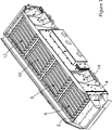
- the screening bars 20, which are typically formed from metal, in each assembly are mounted to a respective support frame 22 arranged such that the bars 20 are mounted in longitudinal alignment with the slope of the deck and the path of the material thereon.
- four screening bar assemblies 6,8,10,12 are provided along the length of the main frame of the screen, arranged inline. More or less sets of screening bars may be utilised depending upon the size of the screen.
- the bars 20 are arranged to define a stepped screening deck over which the feed material passes, undersize material falling through the gaps between the bars to be received in a collection hopper/chute therebelow while larger rocks and boulders pass over the deck to pass over a downstream end of the deck to be delivered onto a conveyor.
- the undersize material may pass over a downstream end of the collection hopper/chute beneath the deck to be delivered onto a second conveyor.
- the main frame may be mounted on a base or chassis of the screen via resilient linkages, such as springs 14, and the frame, and thus the deck may be vibrated by means of a pair of counter rotating rotors defining eccentric masses, driven by one or more drive motors, to impart circular or reciprocating vibratory motion to the deck. Accordingly the deck may be vibrated to agitate the material on the deck of the screen and to encourage undersize material to pass between the sets of bars while conveying the material across the deck such that the oversize material is discharged over a downstream end of the deck onto a conveyor.
- the sets of screening bars may be mounted on a stationary chassis or base, gravity being relied on to convey the material over the deck defined by the bars.
- each bar 20 is coupled to its support frame 22 via compliant mounting blocks 24,26 formed from a different material to the bars, preferably formed from a polymer material although other metallic and non-metallic compliant material are envisaged, and provided at each end of each bar 20 such that there are no welds or bolted connections between the bars 20 and the support frame 22 within which they are mounted, nor any direct metal to metal contact between the relatively rigid metal bars 20 and the relatively rigid metal support frame 22.
- the bars 20 are primarily held in place by a friction or interference fit between the compliant mounting blocks 24,26 and the support frame 22.
- the compliant mounting blocks 24,26 absorb shocks during use which protects the support frame 22 and any component to which it is attached from damage that might otherwise be caused by rocks impacting on the bars 20.
- each mounting block 24,26 comprises a wedge shaped end 28 adapted to be received in a corresponding wedge shaped recess 30 in a respective end of each bar 20. This forces the mounting blocks 24,26 and the bars 20 together under load which helps prevent movement between the mounting blocks 24,26 and the bars 20.
- Each bar 20 may comprise an upper wall 32, a pair of depending side walls 34,36 and a bottom wall 38, end walls 40,42 extending between the bottom wall 38 and upper wall 32, between the side walls 34,36 at either end of each bar 20, said end walls 40,42 extending at an acute angle to said bottom wall 38 to abut the upper wall 32 inwardly from the outer ends of the upper wall 32 such that the ends walls 40,42, side walls 34,36 and a respective outer region of the upper wall 32 define between them said wedge shaped recesses in the respective ends of each bar 20 for receiving a cooperating portion of a respective mounting block 24,26 therein.
- each side wall 34,36 of each bar 20 are shaped such that the side walls do not contact the support frame 22 when the bars 20 are mounted therein via said mounting blocks 24,26.
- the upper wall 32 of each screening bar 20 may be reinforced by an elongate rod 33 or similar strengthening member welded to an upper face thereof to reinforce the bar and resist wear.
- the rods 33 may also serve to break up material and to focus material impact forces towards the centreline or each bar, reducing undesirable edge loading.
- Each support frame 22 comprises parallel side members 44,46 having laterally extending flanges 48,50 to facilitate bolting of the support frames 22 to the main frame of the screen, and a pair of end members 52,54 extending between the side members 44,46.
- Each end member 52,54 has a U shaped profile defining a mounting channel 56,58 having an inwardly facing open side, a portion of each mounting block 24,26 being adapted to engage the mounting channel of a respective end member 52,54 of the support frame 22 to retain the bars 20 in place in the support frame 22.
- each screening bar 20 may have an increasing height (distance between upper wall 32 and bottom wall 38) from one end to the other, preferably from an upstream to a down stream end when installed in the support frame 22 and mounted on the screen. This provides a stepped profile to the deck to facilitate breaking up of the feed material as it traverses the deck.
- An upper end 60 of each screening bar 20 at its deepest portion may extend above the mounting channel 56 of the support frame 22.
- a slot 62 may be formed in the outer end of the respective mounting block 24 mounted in the end of the bar 20 adjacent said upper end 60 of the bar 20 for receiving an upper side of the mounting channel 56 of the support frame 22 therein.
- spacer members 64 are provided to be inserted into the mounting channels 56,58 between the mounting blocks 24,26 of the bars 20.
- retaining bars 66,68 are provided adapted to be bolted to upper faces of the end members 52,54 of the support frame, the retaining bars 66,68 having fingers 70 shaped to extend between the bars 20 to retain the spacer members 64 in position.
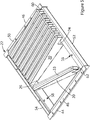
- respective mounting blocks 24,26 are inserted into each end of a respective screening bar 20 and the bar is located in its support frame 22 diagonally to allow the ends of the mounting blocks 24,26 to be received in the mounting channels 56,58 of the support frame 22, the bars subsequently being moved into an operative position parallel to the side members 44,46 of the support frame 22, as illustrated in Figure 5 , causing the mounting blocks 24,26 to engage the mounting channels 56.58 of the support frame 22.
- the spacer members 64 are located between the mounting blocks 24,26 and the retaining plates 66,68 are bolted in place to retain the bars 20 in position within the respective support frame 22.
- the compliant mounting blocks 24, 26 may be formed from any suitably compliant, or resilient, material so that the blocks 24, 26 act as a compliant or resilient coupling, preferably a friction fit coupling, between the bars 20 and the support frame 22, and in particular to act as a shock absorber.
- the compliant mounting blocks 24, 26 may be made from any suitable polymer material, such as polyethylene, polyurethane or natural rubber, although polyethylene may be preferred.
- the mounting blocks 24, 26 may be formed from a metallic or fibrous or composite material.
Landscapes
- Combined Means For Separation Of Solids (AREA)
- Paper (AREA)
Applications Claiming Priority (1)
| Application Number | Priority Date | Filing Date | Title |
|---|---|---|---|
| GB1801107.2A GB2570350B (en) | 2018-01-23 | 2018-01-23 | Screening bar assembly for a screen |
Publications (3)
| Publication Number | Publication Date |
|---|---|
| EP3520908A2 true EP3520908A2 (de) | 2019-08-07 |
| EP3520908A3 EP3520908A3 (de) | 2019-09-11 |
| EP3520908B1 EP3520908B1 (de) | 2023-12-13 |
Family
ID=61283760
Family Applications (1)
| Application Number | Title | Priority Date | Filing Date |
|---|---|---|---|
| EP19151291.2A Active EP3520908B1 (de) | 2018-01-23 | 2019-01-10 | Siebstabanordnung für ein sieb |
Country Status (7)
| Country | Link |
|---|---|
| US (1) | US11198156B2 (de) |
| EP (1) | EP3520908B1 (de) |
| AU (1) | AU2019200384B2 (de) |
| CA (1) | CA3031018A1 (de) |
| FI (1) | FI3520908T3 (de) |
| GB (1) | GB2570350B (de) |
| PL (1) | PL3520908T3 (de) |
Cited By (1)
| Publication number | Priority date | Publication date | Assignee | Title |
|---|---|---|---|---|
| CN110976280A (zh) * | 2019-12-23 | 2020-04-10 | 李淑娴 | 一种建筑工程用筛沙装置 |
Families Citing this family (1)
| Publication number | Priority date | Publication date | Assignee | Title |
|---|---|---|---|---|
| CN114288741B (zh) * | 2022-01-25 | 2023-03-28 | 太原理工大学 | 一种用于煤矿水仓清理的叠振脱水筛 |
Family Cites Families (25)
| Publication number | Priority date | Publication date | Assignee | Title |
|---|---|---|---|---|
| US2790552A (en) * | 1953-01-07 | 1957-04-30 | Nordberg Manufacturing Co | Heavy duty rod grizzly |
| DE1036782B (de) * | 1954-10-22 | 1958-08-21 | Gerhard Hoppe Dipl Ing | Siebboden fuer Schwingsiebe, insbesondere zum Sieben von Feinkohle |
| FR1340492A (fr) * | 1962-11-26 | 1963-10-18 | Stamicarbon | Tamis équipé de barres fixées unilatéralement par le côté d'alimentation |
| US4381235A (en) * | 1980-11-20 | 1983-04-26 | Powerscreen Limited | Screening apparatus |
| FR2510740A1 (fr) * | 1981-07-31 | 1983-02-04 | Regnard Georges | Gabarit perfectionne pour la verification de la taille legale des poissons et analogues |
| FR2515074B1 (fr) * | 1981-10-13 | 1985-10-18 | Femia | Appareil vibrant de triage de produits, notamment de denrees alimentaires telles que des legumes ou fruits |
| SU1005950A1 (ru) * | 1981-11-11 | 1983-03-23 | Днепропетровский Ордена Трудового Красного Знамени Горный Институт Им.Артема | Грохот |
| FR2545385B3 (fr) * | 1983-05-05 | 1986-07-25 | Raggi Jacques | Grille pour crible de premiere separation de calibrage pour produits heterogenes contenant des elements filiformes |
| US5392931A (en) * | 1993-09-30 | 1995-02-28 | Beloit Technologies, Inc. | Adjustable bar screen |
| US5816412A (en) * | 1996-04-02 | 1998-10-06 | Western Wire Works, Inc. | Screening systems and methods for screening particulate material |
| US5901857A (en) * | 1997-05-30 | 1999-05-11 | Beloit Technologies, Inc. | Bar screen bar mount |
| DE19904091A1 (de) * | 1998-03-25 | 1999-09-30 | Isenmann Siebe Gmbh | Siebrost |
| GB0119523D0 (en) * | 2001-08-10 | 2001-10-03 | Ever 1529 Ltd | Screen system |
| DE102005024236A1 (de) * | 2005-05-25 | 2006-11-30 | Isenmann Siebe Gmbh | Siebfläche mit Stangenrost |
| US8162245B2 (en) | 2006-06-22 | 2012-04-24 | Terex Usa, Llc | Mobile aggregate crushing system and method |
| US8136670B2 (en) | 2010-02-08 | 2012-03-20 | Terex Usa, Llc | Collapsible mobile material processing plant with flexible hopper |
| CA2800854C (en) | 2010-06-02 | 2022-07-05 | Technological Resources Pty. Limited | Separating mined material |
| US8915375B2 (en) | 2010-11-08 | 2014-12-23 | Terex Usa, Llc | Vibrating screen suspension systems |
| US9010542B2 (en) | 2011-08-10 | 2015-04-21 | Terex Usa, Llc | Screen lift mechanism for variable slope vibrating screens |
| US9205459B2 (en) | 2012-08-28 | 2015-12-08 | Terex Usa, Llc | Vibrating screen deck deflector systems and methods |
| GB2515445B (en) | 2013-01-18 | 2017-05-24 | Terex Gb Ltd | Material processing apparatus with deployable feed conveyor |
| GB2510839B (en) | 2013-02-14 | 2017-11-01 | Terex Gb Ltd | Material Processing Apparatus with Multi-mode Feed Conveyor Assembly |
| GB2525155B (en) | 2014-02-13 | 2019-02-13 | Terex Gb Ltd | Material screening apparatus with multi-mode screen box |
| GB2524273B (en) | 2014-03-18 | 2017-02-01 | Terex Gb Ltd | Material processing apparatus with auxiliary drive system |
| CN105344579B (zh) * | 2015-11-30 | 2017-05-10 | 天津百利阳光环保设备有限公司 | 一种可调振动式棒条筛分设备 |
-
2018
- 2018-01-23 GB GB1801107.2A patent/GB2570350B/en active Active
-
2019
- 2019-01-10 EP EP19151291.2A patent/EP3520908B1/de active Active
- 2019-01-10 FI FIEP19151291.2T patent/FI3520908T3/fi active
- 2019-01-10 PL PL19151291.2T patent/PL3520908T3/pl unknown
- 2019-01-21 US US16/252,913 patent/US11198156B2/en active Active
- 2019-01-21 AU AU2019200384A patent/AU2019200384B2/en active Active
- 2019-01-22 CA CA3031018A patent/CA3031018A1/en active Pending
Cited By (1)
| Publication number | Priority date | Publication date | Assignee | Title |
|---|---|---|---|---|
| CN110976280A (zh) * | 2019-12-23 | 2020-04-10 | 李淑娴 | 一种建筑工程用筛沙装置 |
Also Published As
| Publication number | Publication date |
|---|---|
| US20190224719A1 (en) | 2019-07-25 |
| PL3520908T3 (pl) | 2024-03-25 |
| AU2019200384A1 (en) | 2019-08-08 |
| GB2570350A (en) | 2019-07-24 |
| GB201801107D0 (en) | 2018-03-07 |
| EP3520908B1 (de) | 2023-12-13 |
| FI3520908T3 (fi) | 2024-02-20 |
| CA3031018A1 (en) | 2019-07-23 |
| EP3520908A3 (de) | 2019-09-11 |
| GB2570350B (en) | 2022-11-30 |
| US11198156B2 (en) | 2021-12-14 |
| AU2019200384B2 (en) | 2024-06-27 |
Similar Documents
| Publication | Publication Date | Title |
|---|---|---|
| US9776214B2 (en) | Multi-deck screening assembly | |
| US6889846B2 (en) | Hybrid screen | |
| US11141760B2 (en) | Screening machine for screening material according to size | |
| JP6109068B2 (ja) | 分離デバイス | |
| US9089877B2 (en) | Backing screen panels for vibrating screen separator | |
| EP2910313B1 (de) | Schirmanordnung | |
| EP3251759B1 (de) | Mehrstöckige siebvorrichtung | |
| US10730055B2 (en) | Method of use of aggregate processing equipment | |
| US2974795A (en) | Grizzly feeders | |
| US11198156B2 (en) | Screening bar assembly for a screen | |
| JP2012206015A (ja) | 破砕機 | |
| EP3090817A1 (de) | Vorrichtung zum trennen von grobkorn von kleineren korngrössen | |
| JP2007000814A (ja) | 分別装置 | |
| GB2067099A (en) | Vibratory screening feeder | |
| CN212468730U (zh) | 一种土石方工程用减噪环保型筛沙机 | |
| CN211865756U (zh) | 一种石料筛分输送设备 | |
| RU195615U1 (ru) | Вибрационный грохот для трудногрохотимой горной массы | |
| KR101810817B1 (ko) | 가압 진동형 모래 선별장치 | |
| CN218796393U (zh) | 一种多功能筛分系统 | |
| CN220590778U (zh) | 一种给料机防堵栅条 | |
| RU2789769C1 (ru) | Способ формирования отвалов с отделением обогащенной мелкой фракции | |
| US20250170582A1 (en) | Crusher screening unit | |
| JP2021169064A (ja) | 篩分け装置 | |
| KR20070008376A (ko) | 다수개의 빔이 설치된 휘다 | |
| RU2074034C1 (ru) | Способ разделения сыпучего материала и сито для его осуществления |
Legal Events
| Date | Code | Title | Description |
|---|---|---|---|
| PUAI | Public reference made under article 153(3) epc to a published international application that has entered the european phase |
Free format text: ORIGINAL CODE: 0009012 |
|
| STAA | Information on the status of an ep patent application or granted ep patent |
Free format text: STATUS: THE APPLICATION HAS BEEN PUBLISHED |
|
| AK | Designated contracting states |
Kind code of ref document: A2 Designated state(s): AL AT BE BG CH CY CZ DE DK EE ES FI FR GB GR HR HU IE IS IT LI LT LU LV MC MK MT NL NO PL PT RO RS SE SI SK SM TR |
|
| AX | Request for extension of the european patent |
Extension state: BA ME |
|
| PUAL | Search report despatched |
Free format text: ORIGINAL CODE: 0009013 |
|
| AK | Designated contracting states |
Kind code of ref document: A3 Designated state(s): AL AT BE BG CH CY CZ DE DK EE ES FI FR GB GR HR HU IE IS IT LI LT LU LV MC MK MT NL NO PL PT RO RS SE SI SK SM TR |
|
| AX | Request for extension of the european patent |
Extension state: BA ME |
|
| RIC1 | Information provided on ipc code assigned before grant |
Ipc: B07B 1/12 20060101AFI20190807BHEP Ipc: B07B 1/46 20060101ALI20190807BHEP |
|
| STAA | Information on the status of an ep patent application or granted ep patent |
Free format text: STATUS: REQUEST FOR EXAMINATION WAS MADE |
|
| 17P | Request for examination filed |
Effective date: 20200311 |
|
| RBV | Designated contracting states (corrected) |
Designated state(s): AL AT BE BG CH CY CZ DE DK EE ES FI FR GB GR HR HU IE IS IT LI LT LU LV MC MK MT NL NO PL PT RO RS SE SI SK SM TR |
|
| STAA | Information on the status of an ep patent application or granted ep patent |
Free format text: STATUS: EXAMINATION IS IN PROGRESS |
|
| 17Q | First examination report despatched |
Effective date: 20220126 |
|
| GRAP | Despatch of communication of intention to grant a patent |
Free format text: ORIGINAL CODE: EPIDOSNIGR1 |
|
| STAA | Information on the status of an ep patent application or granted ep patent |
Free format text: STATUS: GRANT OF PATENT IS INTENDED |
|
| P01 | Opt-out of the competence of the unified patent court (upc) registered |
Effective date: 20230530 |
|
| INTG | Intention to grant announced |
Effective date: 20230707 |
|
| GRAS | Grant fee paid |
Free format text: ORIGINAL CODE: EPIDOSNIGR3 |
|
| GRAA | (expected) grant |
Free format text: ORIGINAL CODE: 0009210 |
|
| STAA | Information on the status of an ep patent application or granted ep patent |
Free format text: STATUS: THE PATENT HAS BEEN GRANTED |
|
| AK | Designated contracting states |
Kind code of ref document: B1 Designated state(s): AL AT BE BG CH CY CZ DE DK EE ES FI FR GR HR HU IE IS IT LI LT LU LV MC MK MT NL NO PL PT RO RS SE SI SK SM TR |
|
| RBV | Designated contracting states (corrected) |
Designated state(s): AL AT BE BG CH CY CZ DE DK EE ES FI FR GR HR HU IE IS IT LI LT LU LV MC MK MT NL NO PL PT RO RS SE SI SK SM TR |
|
| REG | Reference to a national code |
Ref country code: CH Ref legal event code: EP |
|
| REG | Reference to a national code |
Ref country code: DE Ref legal event code: R096 Ref document number: 602019043080 Country of ref document: DE |
|
| REG | Reference to a national code |
Ref country code: IE Ref legal event code: FG4D |
|
| REG | Reference to a national code |
Ref country code: FI Ref legal event code: FGE |
|
| PG25 | Lapsed in a contracting state [announced via postgrant information from national office to epo] |
Ref country code: GR Free format text: LAPSE BECAUSE OF FAILURE TO SUBMIT A TRANSLATION OF THE DESCRIPTION OR TO PAY THE FEE WITHIN THE PRESCRIBED TIME-LIMIT Effective date: 20240314 |
|
| REG | Reference to a national code |
Ref country code: LT Ref legal event code: MG9D |
|
| PG25 | Lapsed in a contracting state [announced via postgrant information from national office to epo] |
Ref country code: LT Free format text: LAPSE BECAUSE OF FAILURE TO SUBMIT A TRANSLATION OF THE DESCRIPTION OR TO PAY THE FEE WITHIN THE PRESCRIBED TIME-LIMIT Effective date: 20231213 |
|
| REG | Reference to a national code |
Ref country code: NL Ref legal event code: MP Effective date: 20231213 |
|
| PG25 | Lapsed in a contracting state [announced via postgrant information from national office to epo] |
Ref country code: ES Free format text: LAPSE BECAUSE OF FAILURE TO SUBMIT A TRANSLATION OF THE DESCRIPTION OR TO PAY THE FEE WITHIN THE PRESCRIBED TIME-LIMIT Effective date: 20231213 |
|
| PG25 | Lapsed in a contracting state [announced via postgrant information from national office to epo] |
Ref country code: LT Free format text: LAPSE BECAUSE OF FAILURE TO SUBMIT A TRANSLATION OF THE DESCRIPTION OR TO PAY THE FEE WITHIN THE PRESCRIBED TIME-LIMIT Effective date: 20231213 Ref country code: GR Free format text: LAPSE BECAUSE OF FAILURE TO SUBMIT A TRANSLATION OF THE DESCRIPTION OR TO PAY THE FEE WITHIN THE PRESCRIBED TIME-LIMIT Effective date: 20240314 Ref country code: ES Free format text: LAPSE BECAUSE OF FAILURE TO SUBMIT A TRANSLATION OF THE DESCRIPTION OR TO PAY THE FEE WITHIN THE PRESCRIBED TIME-LIMIT Effective date: 20231213 Ref country code: BG Free format text: LAPSE BECAUSE OF FAILURE TO SUBMIT A TRANSLATION OF THE DESCRIPTION OR TO PAY THE FEE WITHIN THE PRESCRIBED TIME-LIMIT Effective date: 20240313 |
|
| PG25 | Lapsed in a contracting state [announced via postgrant information from national office to epo] |
Ref country code: NL Free format text: LAPSE BECAUSE OF FAILURE TO SUBMIT A TRANSLATION OF THE DESCRIPTION OR TO PAY THE FEE WITHIN THE PRESCRIBED TIME-LIMIT Effective date: 20231213 |
|
| PG25 | Lapsed in a contracting state [announced via postgrant information from national office to epo] |
Ref country code: SE Free format text: LAPSE BECAUSE OF FAILURE TO SUBMIT A TRANSLATION OF THE DESCRIPTION OR TO PAY THE FEE WITHIN THE PRESCRIBED TIME-LIMIT Effective date: 20231213 Ref country code: RS Free format text: LAPSE BECAUSE OF FAILURE TO SUBMIT A TRANSLATION OF THE DESCRIPTION OR TO PAY THE FEE WITHIN THE PRESCRIBED TIME-LIMIT Effective date: 20231213 Ref country code: NO Free format text: LAPSE BECAUSE OF FAILURE TO SUBMIT A TRANSLATION OF THE DESCRIPTION OR TO PAY THE FEE WITHIN THE PRESCRIBED TIME-LIMIT Effective date: 20240313 Ref country code: NL Free format text: LAPSE BECAUSE OF FAILURE TO SUBMIT A TRANSLATION OF THE DESCRIPTION OR TO PAY THE FEE WITHIN THE PRESCRIBED TIME-LIMIT Effective date: 20231213 Ref country code: LV Free format text: LAPSE BECAUSE OF FAILURE TO SUBMIT A TRANSLATION OF THE DESCRIPTION OR TO PAY THE FEE WITHIN THE PRESCRIBED TIME-LIMIT Effective date: 20231213 Ref country code: HR Free format text: LAPSE BECAUSE OF FAILURE TO SUBMIT A TRANSLATION OF THE DESCRIPTION OR TO PAY THE FEE WITHIN THE PRESCRIBED TIME-LIMIT Effective date: 20231213 |
|
| PG25 | Lapsed in a contracting state [announced via postgrant information from national office to epo] |
Ref country code: IS Free format text: LAPSE BECAUSE OF FAILURE TO SUBMIT A TRANSLATION OF THE DESCRIPTION OR TO PAY THE FEE WITHIN THE PRESCRIBED TIME-LIMIT Effective date: 20240413 |
|
| REG | Reference to a national code |
Ref country code: AT Ref legal event code: UEP Ref document number: 1640045 Country of ref document: AT Kind code of ref document: T Effective date: 20231213 |
|
| PG25 | Lapsed in a contracting state [announced via postgrant information from national office to epo] |
Ref country code: CZ Free format text: LAPSE BECAUSE OF FAILURE TO SUBMIT A TRANSLATION OF THE DESCRIPTION OR TO PAY THE FEE WITHIN THE PRESCRIBED TIME-LIMIT Effective date: 20231213 |
|
| PG25 | Lapsed in a contracting state [announced via postgrant information from national office to epo] |
Ref country code: SK Free format text: LAPSE BECAUSE OF FAILURE TO SUBMIT A TRANSLATION OF THE DESCRIPTION OR TO PAY THE FEE WITHIN THE PRESCRIBED TIME-LIMIT Effective date: 20231213 |
|
| PG25 | Lapsed in a contracting state [announced via postgrant information from national office to epo] |
Ref country code: SM Free format text: LAPSE BECAUSE OF FAILURE TO SUBMIT A TRANSLATION OF THE DESCRIPTION OR TO PAY THE FEE WITHIN THE PRESCRIBED TIME-LIMIT Effective date: 20231213 Ref country code: SK Free format text: LAPSE BECAUSE OF FAILURE TO SUBMIT A TRANSLATION OF THE DESCRIPTION OR TO PAY THE FEE WITHIN THE PRESCRIBED TIME-LIMIT Effective date: 20231213 Ref country code: RO Free format text: LAPSE BECAUSE OF FAILURE TO SUBMIT A TRANSLATION OF THE DESCRIPTION OR TO PAY THE FEE WITHIN THE PRESCRIBED TIME-LIMIT Effective date: 20231213 Ref country code: IS Free format text: LAPSE BECAUSE OF FAILURE TO SUBMIT A TRANSLATION OF THE DESCRIPTION OR TO PAY THE FEE WITHIN THE PRESCRIBED TIME-LIMIT Effective date: 20240413 Ref country code: EE Free format text: LAPSE BECAUSE OF FAILURE TO SUBMIT A TRANSLATION OF THE DESCRIPTION OR TO PAY THE FEE WITHIN THE PRESCRIBED TIME-LIMIT Effective date: 20231213 Ref country code: CZ Free format text: LAPSE BECAUSE OF FAILURE TO SUBMIT A TRANSLATION OF THE DESCRIPTION OR TO PAY THE FEE WITHIN THE PRESCRIBED TIME-LIMIT Effective date: 20231213 |
|
| PG25 | Lapsed in a contracting state [announced via postgrant information from national office to epo] |
Ref country code: PT Free format text: LAPSE BECAUSE OF FAILURE TO SUBMIT A TRANSLATION OF THE DESCRIPTION OR TO PAY THE FEE WITHIN THE PRESCRIBED TIME-LIMIT Effective date: 20240415 |
|
| PG25 | Lapsed in a contracting state [announced via postgrant information from national office to epo] |
Ref country code: PT Free format text: LAPSE BECAUSE OF FAILURE TO SUBMIT A TRANSLATION OF THE DESCRIPTION OR TO PAY THE FEE WITHIN THE PRESCRIBED TIME-LIMIT Effective date: 20240415 |
|
| REG | Reference to a national code |
Ref country code: CH Ref legal event code: PL |
|
| PG25 | Lapsed in a contracting state [announced via postgrant information from national office to epo] |
Ref country code: LU Free format text: LAPSE BECAUSE OF NON-PAYMENT OF DUE FEES Effective date: 20240110 |
|
| REG | Reference to a national code |
Ref country code: DE Ref legal event code: R097 Ref document number: 602019043080 Country of ref document: DE |
|
| PG25 | Lapsed in a contracting state [announced via postgrant information from national office to epo] |
Ref country code: LU Free format text: LAPSE BECAUSE OF NON-PAYMENT OF DUE FEES Effective date: 20240110 Ref country code: MC Free format text: LAPSE BECAUSE OF FAILURE TO SUBMIT A TRANSLATION OF THE DESCRIPTION OR TO PAY THE FEE WITHIN THE PRESCRIBED TIME-LIMIT Effective date: 20231213 |
|
| PG25 | Lapsed in a contracting state [announced via postgrant information from national office to epo] |
Ref country code: DK Free format text: LAPSE BECAUSE OF FAILURE TO SUBMIT A TRANSLATION OF THE DESCRIPTION OR TO PAY THE FEE WITHIN THE PRESCRIBED TIME-LIMIT Effective date: 20231213 |
|
| PLBE | No opposition filed within time limit |
Free format text: ORIGINAL CODE: 0009261 |
|
| STAA | Information on the status of an ep patent application or granted ep patent |
Free format text: STATUS: NO OPPOSITION FILED WITHIN TIME LIMIT |
|
| PG25 | Lapsed in a contracting state [announced via postgrant information from national office to epo] |
Ref country code: CH Free format text: LAPSE BECAUSE OF NON-PAYMENT OF DUE FEES Effective date: 20240131 |
|
| PG25 | Lapsed in a contracting state [announced via postgrant information from national office to epo] |
Ref country code: SI Free format text: LAPSE BECAUSE OF FAILURE TO SUBMIT A TRANSLATION OF THE DESCRIPTION OR TO PAY THE FEE WITHIN THE PRESCRIBED TIME-LIMIT Effective date: 20231213 |
|
| PG25 | Lapsed in a contracting state [announced via postgrant information from national office to epo] |
Ref country code: SI Free format text: LAPSE BECAUSE OF FAILURE TO SUBMIT A TRANSLATION OF THE DESCRIPTION OR TO PAY THE FEE WITHIN THE PRESCRIBED TIME-LIMIT Effective date: 20231213 Ref country code: DK Free format text: LAPSE BECAUSE OF FAILURE TO SUBMIT A TRANSLATION OF THE DESCRIPTION OR TO PAY THE FEE WITHIN THE PRESCRIBED TIME-LIMIT Effective date: 20231213 Ref country code: CH Free format text: LAPSE BECAUSE OF NON-PAYMENT OF DUE FEES Effective date: 20240131 |
|
| 26N | No opposition filed |
Effective date: 20240916 |
|
| PG25 | Lapsed in a contracting state [announced via postgrant information from national office to epo] |
Ref country code: IE Free format text: LAPSE BECAUSE OF NON-PAYMENT OF DUE FEES Effective date: 20240110 |
|
| PG25 | Lapsed in a contracting state [announced via postgrant information from national office to epo] |
Ref country code: IE Free format text: LAPSE BECAUSE OF NON-PAYMENT OF DUE FEES Effective date: 20240110 |
|
| PG25 | Lapsed in a contracting state [announced via postgrant information from national office to epo] |
Ref country code: CY Free format text: LAPSE BECAUSE OF FAILURE TO SUBMIT A TRANSLATION OF THE DESCRIPTION OR TO PAY THE FEE WITHIN THE PRESCRIBED TIME-LIMIT; INVALID AB INITIO Effective date: 20190110 |
|
| PG25 | Lapsed in a contracting state [announced via postgrant information from national office to epo] |
Ref country code: HU Free format text: LAPSE BECAUSE OF FAILURE TO SUBMIT A TRANSLATION OF THE DESCRIPTION OR TO PAY THE FEE WITHIN THE PRESCRIBED TIME-LIMIT; INVALID AB INITIO Effective date: 20190110 |
|
| PG25 | Lapsed in a contracting state [announced via postgrant information from national office to epo] |
Ref country code: TR Free format text: LAPSE BECAUSE OF FAILURE TO SUBMIT A TRANSLATION OF THE DESCRIPTION OR TO PAY THE FEE WITHIN THE PRESCRIBED TIME-LIMIT Effective date: 20231213 |
|
| PGFP | Annual fee paid to national office [announced via postgrant information from national office to epo] |
Ref country code: PL Payment date: 20251219 Year of fee payment: 8 |
|
| PGFP | Annual fee paid to national office [announced via postgrant information from national office to epo] |
Ref country code: DE Payment date: 20260121 Year of fee payment: 8 |
|
| PGFP | Annual fee paid to national office [announced via postgrant information from national office to epo] |
Ref country code: AT Payment date: 20260122 Year of fee payment: 8 |
|
| PGFP | Annual fee paid to national office [announced via postgrant information from national office to epo] |
Ref country code: BE Payment date: 20260121 Year of fee payment: 8 Ref country code: FI Payment date: 20260129 Year of fee payment: 8 Ref country code: IT Payment date: 20260126 Year of fee payment: 8 |
|
| PGFP | Annual fee paid to national office [announced via postgrant information from national office to epo] |
Ref country code: FR Payment date: 20260123 Year of fee payment: 8 |