EP3520926A1 - Vorrichtung und verfahren zum pumpen heisser schmelzen - Google Patents
Vorrichtung und verfahren zum pumpen heisser schmelzen Download PDFInfo
- Publication number
- EP3520926A1 EP3520926A1 EP19155824.6A EP19155824A EP3520926A1 EP 3520926 A1 EP3520926 A1 EP 3520926A1 EP 19155824 A EP19155824 A EP 19155824A EP 3520926 A1 EP3520926 A1 EP 3520926A1
- Authority
- EP
- European Patent Office
- Prior art keywords
- riser
- pump head
- pipe
- melt
- drain pipe
- Prior art date
- Legal status (The legal status is an assumption and is not a legal conclusion. Google has not performed a legal analysis and makes no representation as to the accuracy of the status listed.)
- Granted
Links
Images

Classifications
-
- B—PERFORMING OPERATIONS; TRANSPORTING
- B22—CASTING; POWDER METALLURGY
- B22D—CASTING OF METALS; CASTING OF OTHER SUBSTANCES BY THE SAME PROCESSES OR DEVICES
- B22D35/00—Equipment for conveying molten metal into beds or moulds
-
- F—MECHANICAL ENGINEERING; LIGHTING; HEATING; WEAPONS; BLASTING
- F04—POSITIVE - DISPLACEMENT MACHINES FOR LIQUIDS; PUMPS FOR LIQUIDS OR ELASTIC FLUIDS
- F04F—PUMPING OF FLUID BY DIRECT CONTACT OF ANOTHER FLUID OR BY USING INERTIA OF FLUID TO BE PUMPED; SIPHONS
- F04F1/00—Pumps using positively or negatively pressurised fluid medium acting directly on the liquid to be pumped
- F04F1/18—Pumps using positively or negatively pressurised fluid medium acting directly on the liquid to be pumped the fluid medium being mixed with, or generated from the liquid to be pumped
-
- F—MECHANICAL ENGINEERING; LIGHTING; HEATING; WEAPONS; BLASTING
- F27—FURNACES; KILNS; OVENS; RETORTS
- F27D—DETAILS OR ACCESSORIES OF FURNACES, KILNS, OVENS OR RETORTS, IN SO FAR AS THEY ARE OF KINDS OCCURRING IN MORE THAN ONE KIND OF FURNACE
- F27D27/00—Stirring devices for molten material
- F27D27/005—Pumps
-
- F—MECHANICAL ENGINEERING; LIGHTING; HEATING; WEAPONS; BLASTING
- F27—FURNACES; KILNS; OVENS; RETORTS
- F27D—DETAILS OR ACCESSORIES OF FURNACES, KILNS, OVENS OR RETORTS, IN SO FAR AS THEY ARE OF KINDS OCCURRING IN MORE THAN ONE KIND OF FURNACE
- F27D3/00—Charging; Discharging; Manipulation of charge
- F27D3/14—Charging or discharging liquid or molten material
Definitions
- Melting refers here to melts of metals, of metal alloys and of metal compounds, such as sulfides or arsenides.
- the GB 1125005 A Figure 12 shows the stepwise pumping of molten metal from one open vessel to another higher open vessel where the exit of the end bent riser simply terminates at the edge of the next vessel.
- the US 4590988 A also shows a bent at the end riser, which is divided at the output in a drain pipe and a ventilation opening. In these embodiments, the molten metal may come into contact with ambient air.
- the purity of a melt is decisive for the quality of the workpiece or semi-finished product produced from it.
- a reduced purity of the melt can further processing, such as casting or atomizing, rubbing, in particular by means of rotary elements such as Schleudersieben or Sliding cages, adversely affect. It is therefore necessary for many melts that they are melted and conveyed under an inert atmosphere.
- a device in which a designed as a closed housing pump head is provided, in which the riser and the drain pipe open, and at least one, the riser and the drain pipe opposite, gas exhaust pipe for removing the conveying gas, said the pump head has a larger cross section than the riser, the drain pipe or the gas exhaust pipe. In most cases, the pump head will have a diameter which is greater than the sum of the diameter of riser and drain pipe.
- the pump head thus forms a housing which shields the melt and the escaping from the melt conveying gas relative to the ambient air in the operating state.
- the melt flows from the riser to the bottom of the pump head and from there gas bubble free in the drain pipe, while the emerging from the melt carrier gas collects at the top of the pump head and escaped through the gas exhaust pipe or pumped out.
- Inert gas is used as the conveying gas in a manner known per se, for example nitrogen or other inert gases (eg argon, hydrogen, etc.).
- a melt filter also referred to as a frit, mounted in front of the mouth of the conveying gas line or in front of the entrance or in the entrance of the riser.
- a frit is a porous filter made of glass or ceramic or of combination elements comprising glass and / or ceramic, which distributes the inert gas.
- the riser is usually a straight pipe.
- the delivery gas line usually ends at the entrance or slightly inside the entrance of the riser.
- the inner diameter of the conveying gas line is usually only 2 to 20% of the inner diameter of the riser.
- the inner diameter of the riser is usually larger than that of the drain pipe.
- the inner diameter of the gas exhaust pipe is usually smaller than the inner diameter of the riser and the inner diameter of the drain pipe.
- the pump head has a bottom, which is in the operating state at the bottom of the pump head.
- the riser pipe and the drain pipe usually open into the bottom of the pump head, the gas exhaust pipe usually opens at the opposite wall of the floor (ceiling) or at the top of the pump head.
- the conveying gas can be removed through the gas exhaust pipe and disposed of, so escape during pumping no gases or dusts uncontrolled.
- the riser seen in the direction of the riser, further protrudes into the pump head than the drain pipe, it is ensured that in the operating state, the melt covers the entrance of the drain pipe and thus can not reach a reactive gas in the drain pipe or the melt running therein.
- the closed pump head it is ensured by the closed pump head, that only the escaping from the melt carrier gas, which is an inert gas, located in the pump head. If the gas exhaust pipe, which serves to divert the conveying gas, be defective, so at least the drain pipe would be shielded by the melt of ambient air.
- the shielding of the melt is further improved by the fact that an overflow pipe opens into the pump head, that its end, seen in the direction of the riser, further protrudes into the pump head than the riser, and that melt flow freely from the pump head in the operating state of the device can. That is, in the operating state of the device is the end of the Overflow pipe higher than the end of the riser and thus in any case higher than the end of the drain pipe.
- the overflow pipe also ensures that the level of the melt can not rise above the overflow pipe.
- the overflow pipe then usually opens again in those container from which the melt is pumped up with the riser pipe, whereby a closed melt cycle is ensured.
- the inner diameter of the overflow pipe is usually larger than that of the drain pipe, but less than or equal to that of the riser. In most cases, the pump head will then have a diameter (normal to the longitudinal axis of the riser) that is greater than the sum of the diameter of riser and downcomer and overflow tube.
- the riser extends into the pump head to 200 mm, preferably 40-100 mm.
- the drain pipe When the drain pipe opens into the bottom of the pump head, it is ensured that the drain pipe in the operating state of the device does not end above the riser pipe or possibly not above the overflow pipe. Because the bottom of the pump head is in the operating state of the deepest region of the pump head.
- An embodiment of the invention provides a second riser, which is arranged so that melt can be pumped out of the pump head.
- melt can be pumped from the pump head to a greater height, if the first riser alone is not sufficient for such a high altitude.
- the second riser then preferably belongs to a device which is formed again according to the invention. In this way, two or more devices according to the invention can be arranged one above the other like a cascade. In other words, the sump of the pump head can be used as a suction for a further pumping stage.
- the device according to the invention can be used for pumping melts of metals, alloys or metal compounds, in particular for metal compounds such as sulfides or arsenides.
- metal compounds such as sulfides or arsenides.
- Vapor escaping from the melt a shielding of the environment through the pump head desired.
- At least the riser pipe is preheated during startup, that is to say before the delivery gas is switched on.
- other parts of the device according to the invention can also be preheated. By preheating damage can be avoided by a sudden heat of the melt at the parts of the device according to the invention.
- the device according to the invention can be applied to melts of metals, of metal alloys and of metal compounds, such as sulfides or arsenides.
- Suitable metals or as constituents of the metal alloys or as constituents of the metal compounds are, for example, aluminum, magnesium, tin, lead, copper, iron, nickel, bismuth or zinc.
- the individual components of the device according to the invention must be compatible with the melts to be pumped.
- steel, graphite or refractory ceramics are possible.
- the device can be made of refractory semi-finished simple geometry, preferably from pipes and plates.
- a device according to the invention is shown in operation.
- the necessary pressure difference between inlet (intake), bottom, and outlet (outlet), top of the riser 1 is carried out by introducing inert gas 2 via a conveying gas line 4 in the melt 3.
- the riser 1 dips into a vessel with melt 3, eg an oven, pan or pan.
- the introduced inert gas 2 forms bubbles 5 in the melt 3.
- Bubble formation can take place via a frit 10 (see FIG Fig. 2 ), which is located in front of the mouth of the conveying gas line 4.
- the resulting temporary gas-melt mixture has a lower density compared to the melt 3 and increases in the riser 1, which prevents the separation of melt and gas.
- the mixture finally discharges into the pump head 6, which has a substantially larger cross-section than the riser 1.
- the delivery gas can be controlled via the gas exhaust pipe 7 discharged and disposed of.
- the melt can via the drain pipe 8 in a closed Piping system are routed.
- the overflow 9 returns the excess melt into the original melt vessel.
- the delivery rate of the melt 3 can be adjusted by means of the amount of the inert gas 2.
- the inert gas 2 heats up to the melt temperature. It expands and requires a larger volume, which has a positive effect on gas consumption.
- Fig. 2 shows an alternative embodiment of the entrance of the riser 1, which extends away from the pump head 6 in the form of a funnel 11.
- the conveying gas line 4 made of steel has an inner diameter of 4 mm and a wall thickness of 1 mm.
- the conveying gas line 4 opens open and centric in the riser 1, namely 50 mm above the entrance of the riser 1.
- nitrogen is used as the inert gas 2.
- a gas volume flow of 0.62 Nm 3 / h promotes a melt quantity of 500 kg / h, a gas volume flow of 1.1 Nm 3 / h promotes even 1000 kg / h.
- the head is 500 mm above the tin melting level of the furnace from which the melt 3 is pumped out.
- the entrance of the riser 1 made of heat-resistant steel with an inner diameter of 30 mm and a wall thickness of 5 mm to a depth of 320 mm.
- the Delivery gas line 4 made of steel has an inner diameter of 4 mm and a wall thickness of 1 mm.
- the conveying gas line 4 opens open and centric in the riser 1, namely 50 mm above the entrance of the riser 1.
- nitrogen is used as the inert gas 2.
- a gas volume flow of 0.49 Nm 3 / h promotes a melt quantity of 220 kg / h.
- the head is 400 mm above the magnesium melt level of the furnace from which the melt 3 is pumped out.
Landscapes
- Engineering & Computer Science (AREA)
- Mechanical Engineering (AREA)
- General Engineering & Computer Science (AREA)
- Structures Of Non-Positive Displacement Pumps (AREA)
Abstract
Description
- Die Erfindung betrifft eine Vorrichtung zum Pumpen von heißen Schmelzen unter Verwendung des Mammutpumpeneffekts, die Vorrichtung umfassend
- ein beidseitig offenes Steigrohr, das an seinem Ausgang mit zumindest einem Ablaufrohr über einen Pumpenkopf in Verbindung steht,
- eine Fördergasleitung, die im Bereich des Eingangs des Steigrohrs endet, zum Fördern von Schmelze durch das Steigrohr,
- ein Ablaufrohr, durch welches im Betriebszustand der Vorrichtung heiße, aus dem Steigrohr aufsteigende Schmelze frei abfließen kann.
- Als Schmelzen werden hier Schmelzen aus Metallen, aus Metalllegierungen und aus Metallverbindungen, wie Sulfide oder Arsenide, bezeichnet.
- Es ist bekannt, den Mammutpumpeneffekt zum Fördern von heißen Metallschmelzen einzusetzen. Die
GB 1125005 A US 4590988 A zeigt ebenfalls ein am Ende gebogenes Steigrohr, das sich am Ausgang in ein Ablaufrohr und eine Lüftungsöffnung aufteilt. Bei diesen Ausführungsformen kann die Metallschmelze mit Umgebungsluft in Berührung kommen. - Die Reinheit einer Schmelze ist entscheidend für die Qualität des aus ihr hergestellten Werkstücks oder Halbzeuges. Eine verminderte Reinheit der Schmelze kann die Weiterverarbeitung, etwa das Gießen oder Verdüsen, Verschleudern, insbesondere mittels Rotationselementen wie Schleudersieben oder Schleuderkäfigen, negativ beeinflussen. Es ist daher bei vielen Schmelzen erforderlich, dass diese unter inerter Atmosphäre erschmolzen und gefördert werden.
- Es ist daher eine Aufgabe der vorliegenden Erfindung, eine Vorrichtung zum Pumpen von heißen Schmelzen zur Verfügung zu stellen, mit der die Schmelze beim Transport von der Umgebungsluft weitgehend abgeschirmt ist.
- Diese Aufgabe wird durch eine Vorrichtung gemäß Anspruch 1 gelöst, bei welcher ein als abgeschlossenes Gehäuse ausgebildeter Pumpenkopf vorgesehen ist, in welchen das Steigrohr und das Ablaufrohr münden, sowie zumindest ein, dem Steigrohr und dem Ablaufrohr gegenüber liegendes, Gasabzugsrohr zum Entfernen des Fördergases, wobei der Pumpenkopf einen größeren Querschnitt aufweist als das Steigrohr, das Ablaufrohr oder das Gasabzugsrohr. Meist wird der Pumpenkopf einen Durchmesser aufweisen, der größer ist als die Summe der Durchmesser von Steigrohr und Ablaufrohr.
- Der Pumpenkopf bildet somit ein Gehäuse, das im Betriebszustand die Schmelze und das aus der Schmelze entweichende Fördergas gegenüber der Umgebungsluft abschirmt. Die Schmelze fließt aus dem Steigrohr zum Boden des Pumpenkopfs und von dort gasblasenfrei in das Ablaufrohr, während das aus der Schmelze austretende Fördergas sich oben im Pumpenkopf sammelt und über das Gasabzugsrohr entweicht oder abgepumpt wird.
- Als Fördergas wird in an sich bekannter Weise Inertgas verwendet, etwa Stickstoff oder andere Inertgase (z.B. Argon, Wasserstoff etc). Um ausreichend kleine Blasen von Inertgas im Steigrohr zu erzeugen, wird ein Schmelzefilter, auch als Fritte bezeichnet, vor der Mündung der Fördergasleitung angebracht bzw. vor dem Eingang oder im Eingang des Steigrohrs. Eine Fritte ist ein poröser Filter aus Glas oder Keramik oder aus Kombinationselementen umfassend Glas und/oder Keramik, der das Inertgas verteilt.
- Das Steigrohr ist in der Regel ein gerades Rohr. Die Fördergasleitung endet meist am Eingang oder etwas innerhalb des Eingangs des Steigrohrs. Der Innendurchmesser der Fördergasleitung beträgt in der Regel nur 2 bis 20% des Innendurchmessers des Steigrohrs. Der Innendurchmesser des Steigrohrs ist in der Regel größer als jener des Ablaufrohrs. Der Innendurchmesser des Gasabzugsrohrs ist in der Regel kleiner als der Innendurchmesser des Steigrohrs und der Innendurchmesser des Ablaufrohrs.
- Der Pumpenkopf weist einen Boden auf, der sich im Betriebszustand an der Unterseite des Pumpenkopfs befindet. Das Steigrohr und das Ablaufrohr münden in der Regel in den Boden des Pumpenkopfs, das Gasabzugsrohr mündet in der Regel an der dem Boden gegenüberliegenden Wand (Decke) oder am oberen Rand des Pumpenkopfs.
- Mit dem erfindungsgemäßen Pumpenkopf kann das Fördergas durch das Gasabzugsrohr abgeführt und entsorgt werden, sodass beim Pumpen keine Gase oder Stäube unkontrolliert entweichen.
- Dadurch, dass das Steigrohr, in Richtung des Steigrohres gesehen, weiter in den Pumpenkopf hineinragt als das Ablaufrohr, ist sichergestellt, dass im Betriebszustand die Schmelze den Eingang des Ablaufrohres überdeckt und somit kein reaktives Gas in das Ablaufrohr oder zur darin ablaufenden Schmelze gelangen kann. Im Normalfall ist durch den abgeschlossenen Pumpenkopf gewährleistet, dass sich nur das aus der Schmelze entweichende Fördergas, das ein Inertgas ist, im Pumpenkopf befindet. Sollte das Gasabzugsrohr, das der Ableitung des Fördergases dient, defekt sein, so wäre zumindest das Ablaufrohr durch die Schmelze von Umgebungsluft abgeschirmt.
- Die Abschirmung der Schmelze wird dadurch noch weiter verbessert, dass ein Überlaufrohr so in den Pumpenkopf mündet, dass dessen Ende, in Richtung des Steigrohres gesehen, weiter in den Pumpenkopf hineinragt als das Steigrohr, und dass im Betriebszustand der Vorrichtung Schmelze aus dem Pumpenkopf frei abfließen kann. Das heißt, im Betriebszustand der Vorrichtung liegt das Ende des Überlaufrohres höher als das Ende des Steigrohrs und damit jedenfalls höher als das Ende des Ablaufrohrs. Durch das Überlaufrohr wird zudem sichergestellt, dass der Spiegel der Schmelze nicht über das Überlaufrohr hinaus ansteigen kann. Das Überlaufrohr mündet dann in der Regel wieder in jenen Behälter, aus dem die Schmelze mit dem Steigrohr hochgepumpt wird, wodurch ein geschlossener Schmelzekreislauf sichergestellt ist. Der Innendurchmesser des Überlaufrohrs ist in der Regel größer als jener des Ablaufrohrs, aber kleiner oder gleich wie jener des Steigrohrs. Meist wird der Pumpenkopf dann einen Durchmesser (normal zur Längsachse des Steigrohrs) aufweisen, der größer ist als die Summe der Durchmesser von Steigrohr und Ablaufrohr und Überlaufrohr.
- Eine vorteilhafte Ausgestaltung der Erfindung besteht darin, dass das Steigrohr bis 200 mm, vorzugsweise 40-100 mm, in den Pumpenkopf hineinragt.
- Wenn das Ablaufrohr in den Boden des Pumpenkopfes mündet, ist sichergestellt, dass das Ablaufrohr im Betriebszustand der Vorrichtung nicht bis oberhalb des Steigrohrs oder gegebenenfalls nicht oberhalb des Überlaufrohres endet. Denn der Boden des Pumpenkopfes ist im Betriebszustand der tiefste Bereich des Pumpenkopfes.
- Eine Ausführungsvariante der Erfindung sieht ein zweites Steigrohr vor, welches so angeordnet ist, dass Schmelze aus dem Pumpenkopf herausgepumpt werden kann. Damit kann also Schmelze aus dem Pumpenkopf auf eine größere Höhe gepumpt werden, falls das erste Steigrohr alleine für eine so große Höhe nicht ausreicht. Das zweite Steigrohr gehört dann vorzugsweise zu einer Vorrichtung, die wieder erfindungsgemäß ausgebildet ist. Auf diese Weise können zwei oder auch mehrere erfindungsgemäße Vorrichtungen kaskadenartig übereinander angeordnet werden. Mit anderen Worten kann der Sumpf des Pumpenkopfs als Ansaugraum für eine weitere Pumpstufe genutzt werden.
- Die erfindungsgemäße Vorrichtung kann zum Pumpen von Schmelzen aus Metallen, Legierungen oder Metallverbindungen verwendet werden, insbesondere für Metallverbindungen wie Sulfide oder Arsenide. Hier ist oft auch aufgrund der Dämpfe, die aus der Schmelze austreten, eine Abschirmung der Umgebung durch den Pumpenkopf erwünscht.
- Das erfindungsgemäße Verfahren zum Pumpen von heißen Schmelzen unter Verwendung des Mammutpumpeneffekts, wird durchgeführt unter Verwendung einer Vorrichtung umfassend
- ein beidseitig offenes Steigrohr, das an seinem Ausgang mit zumindest einem Ablaufrohr über einen Pumpenkopf in Verbindung steht,
- eine Fördergasleitung, die im Bereich des Eingangs des Steigrohrs endet,
- vorzugsweise ein Ablaufrohr, durch welches im Betriebszustand der Vorrichtung heiße, aus dem Steigrohr aufsteigende Schmelze, frei abfließen kann,
- einen als abgeschlossenes Gehäuse ausgebildeten Pumpenkopf, in welchen das Steigrohr und das Ablaufrohr münden, sowie zumindest ein, dem Steigrohr und dem Ablaufrohr gegenüber liegendes, Gasabzugsrohr zum Entfernen des Fördergases, wobei der Pumpenkopf einen größeren Querschnitt aufweist als das Steigrohr, das Ablaufrohr oder das Gasabzugsrohr, wobei das Steigrohr, in Richtung des Steigrohres gesehen, weiter in den Pumpenkopf hineinragt als das Ablaufrohr, und wobei ein Überlaufrohr so in den Pumpenkopf mündet, dass dessen Ende, in Richtung des Steigrohres gesehen, weiter in den Pumpenkopf hineinragt als das Steigrohr, und wobei im Betriebszustand der Vorrichtung Schmelze aus dem Pumpenkopf frei abfließen kann.
- Eintauchen des Eingangs des Steigrohrs in eine Schmelze,
- Einstellung der Gasmenge des Fördergases, sodass der Spiegel der Schmelze im Pumpenkopf oberhalb des Ausgangs des Steigrohres liegt.
- Insbesondere kann vorgesehen sein, dass zumindest das Steigrohr bei Inbetriebnahme, also etwa vor dem Einschalten des Fördergases, vorgewärmt wird. Selbstverständlich können auch weitere Teile der erfindungsgemäßen Vorrichtung vorgewärmt werden. Durch das Vorwärmen können Schäden durch eine plötzliche Hitzeeinwirkung der Schmelze an den Teilen der erfindungsgemäßen Vorrichtung vermieden werden.
- Die erfindungsgemäße Vorrichtung kann auf Schmelzen aus Metallen, aus Metalllegierungen und aus Metallverbindungen, wie Sulfide oder Arsenide, angewendet werden. Als Metalle oder als Bestandteile der Metalllegierungen oder als Bestandteile der Metallverbindungen kommen beispielsweise Aluminium, Magnesium, Zinn, Blei, Kupfer, Eisen, Nickel, Wismut oder Zink in Frage.
- Die einzelnen Bauteile der erfindungsgemäßen Vorrichtung müssen zu den zu pumpenden Schmelzen kompatibel sein. In Frage kommen etwa Stahl, Graphit oder feuerfeste Keramiken. Die Vorrichtung kann aus feuerfesten Halbzeugen einfacher Geometrie, vorzugsweise aus Rohren und Platten, gefertigt werden.
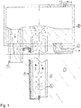
- Die Erfindung wird anhand zweier schematischer Figuren, die jeweils ein mögliches Ausführungsbeispiel darstellen, näher erläutert, wobei
- Fig. 1
- eine erfindungsgemäße Vorrichtung im Längsschnitt und
- Fig. 2
- eine alternative Form des Eingangs des Steigrohrs im Längsschnitt.
- In
Fig. 1 ist eine erfindungsgemäße Vorrichtung im Betrieb dargestellt. Die notwendige Druckdifferenz zwischen Eingang (Ansaugöffnung), unten, und Ausgang (Auslassöffnung), oben, des Steigrohrs 1 erfolgt durch das Einleiten von Inertgas 2 über eine Fördergasleitung 4 in die Schmelze 3. Das Steigrohr 1 taucht in ein Gefäß mit Schmelze 3, z.B. einen Ofen, Tiegel oder Pfanne. Das eingeleitete Inertgas 2 bildet Blasen 5 in der Schmelze 3. Die Blasenbildung kann über eine Fritte 10 (sieheFig. 2 ) unterstützt werden, welche sich vor der Mündung der Fördergasleitung 4 befindet. Das entstehende temporäre Gas-Schmelze-Gemisch besitzt gegenüber der Schmelze 3 eine geringere Dichte und steigt im Steigrohr 1 auf, welches die Entmischung von Schmelze und Gas verhindert. - Das Gemisch mündet schließlich im Pumpenkopf 6, der einen wesentlich größeren Querschnitt besitzt als das Steigrohr 1. Hier findet die Entmischung der beiden Phasen statt. Das Fördergas kann kontrolliert über das Gasabzugsrohr 7 abgeleitet und entsorgt werden. Die Schmelze kann über das Ablaufrohr 8 in ein geschlossenes Rohrsystem geleitet werden. Der Überlauf 9 führt die überschüssige Schmelze in das ursprüngliche Schmelzegefäß zurück.
- Steigrohr 1, Ablaufrohr 8 und Überlauf 9 münden im Boden des Pumpenkopfs 6. In diesem Beispiel ragt der Überlauf 9 am weitesten in das Innere des Pumpenkopfs 6, auch das Steigrohr 1 ragt in das Innere des Pumpenkopfs 6. Nur das Ablaufrohr 8 ragt nicht in das Innere des Pumpenkopfs 6.
- Die Fördermenge der Schmelze 3 kann mittels der Menge des Inertgases 2 eingestellt werden. Beim Einleiten erwärmt sich das Inertgas 2 bis auf die Schmelzetemperatur. Dabei dehnt es sich aus und beansprucht ein größeres Volumen, was sich positiv auf den Gasverbrauch auswirkt.
-
Fig. 2 zeigt eine alternative Ausführungsform des Eingangs des Steigrohrs 1, welches sich vom Pumpenkopf 6 weg in Form eines Trichters 11 erweitert. - Im Folgenden werden zwei Ausführungsbeispiele für den Einsatz der erfindungsgemäßen Vorrichtung gegeben.
- In einer Zinnschmelze mit einer Temperatur von 360° taucht der Eingang des Steigrohrs 1 aus Stahl mit einem Innendurchmesser von 22 mm und einer Wandstärke von 1,5 mm bis in eine Tiefe von 500 mm ein. Die Fördergasleitung 4 aus Stahl hat einen Innendurchmesser von 4 mm und eine Wandstärke von 1 mm. Die Fördergasleitung 4 mündet offen und zentrisch in das Steigrohr 1, und zwar 50 mm oberhalb des Eingangs des Steigrohrs 1. Als Inertgas 2 wird Stickstoff verwendet. Ein Gasvolumenstrom von 0,62 Nm3/h fördert eine Schmelzemenge von 500 kg/h, ein Gasvolumenstrom von 1,1 Nm3/h fördert sogar 1000 kg/h. Die Förderhöhe beträgt 500 mm über dem Zinnschmelzespiegel des Ofens, aus dem die Schmelze 3 herausgepumpt wird.
- In eine Magnesiumschmelze mit einer Temperatur von 700° taucht der Eingang des Steigrohrs 1 aus hochwarmfestem Stahl mit einem Innendurchmesser von 30 mm und einer Wandstärke von 5 mm bis in eine Tiefe von 320 mm ein. Die Fördergasleitung 4 aus Stahl hat einen Innendurchmesser von 4 mm und eine Wandstärke von 1 mm. Die Fördergasleitung 4 mündet offen und zentrisch in das Steigrohr 1, und zwar 50 mm oberhalb des Eingangs des Steigrohrs 1. Als Inertgas 2 wird Stickstoff verwendet. Ein Gasvolumenstrom von 0,49 Nm3/h fördert eine Schmelzemenge von 220 kg/h. Die Förderhöhe beträgt 400 mm über dem Magnesiumschmelzespiegel des Ofens, aus dem die Schmelze 3 herausgepumpt wird.
-
- 1
- Steigrohr
- 2
- Inertgas (Fördergas)
- 3
- Schmelze
- 4
- Fördergasleitung
- 5
- Blase
- 6
- Pumpenkopf
- 7
- Gasabzugsrohr
- 8
- Ablaufrohr
- 9
- Überlauf
- 10
- Fritte
- 11
- Trichter
Claims (8)
- Vorrichtung zum Pumpen von heißen Schmelzen (3) unter Verwendung des Mammutpumpeneffekts, die Vorrichtung umfassend- ein beidseitig offenes Steigrohr (1), das an seinem Ausgang mit zumindest einem Ablaufrohr (8) über einen Pumpenkopf (6) in Verbindung steht,- eine Fördergasleitung (4), die im Bereich des Eingangs des Steigrohrs (1) endet, zum Fördern von Schmelze (3) durch das Steigrohr (1),- ein Ablaufrohr (8), durch welches im Betriebszustand der Vorrichtung heiße, aus dem Steigrohr (1) aufsteigende Schmelze (3) frei abfließen kann, dadurch gekennzeichnet, dass ein als abgeschlossenes Gehäuse ausgebildeter Pumpenkopf (6) vorgesehen ist, in welchen das Steigrohr (1) und das Ablaufrohr (8) münden, sowie zumindest ein, dem Steigrohr (1) und dem Ablaufrohr (8) gegenüber liegendes, Gasabzugsrohr (7) zum Entfernen des Fördergases (2), dass der Pumpenkopf (6) einen größeren Querschnitt aufweist als das Steigrohr (1), das Ablaufrohr (8) oder das Gasabzugsrohr (7), dass das Steigrohr (1), in Richtung des Steigrohres gesehen, weiter in den Pumpenkopf (6) hineinragt als das Ablaufrohr (8) und dass ein Überlaufrohr (9) so in den Pumpenkopf (6) mündet, dass dessen Ende, in Richtung des Steigrohres (1) gesehen, weiter in den Pumpenkopf (6) hineinragt als das Steigrohr (1), und dass im Betriebszustand der Vorrichtung Schmelze (3) aus dem Pumpenkopf (6) frei abfließen kann.
- Vorrichtung nach Anspruch 1, dadurch gekennzeichnet, dass das Steigrohr (1) bis 200 mm, vorzugsweise 40-100 mm, in den Pumpenkopf (6) hineinragt.
- Vorrichtung nach einem der vorhergehenden Ansprüche, dadurch gekennzeichnet, dass das Ablaufrohr (8) in den Boden des Pumpenkopfes (6)mündet.
- Vorrichtung nach einem der vorhergehenden Ansprüche, dadurch gekennzeichnet, dass ein zweites Steigrohr (1) vorgesehen ist, welches so angeordnet ist, dass Schmelze (3) aus dem Pumpenkopf (6) herausgepumpt werden kann.
- Verwendung einer Vorrichtung nach den vorhergehenden Ansprüchen zum Pumpen von Schmelzen (3) aus Metallen, Legierungen oder Metallverbindungen.
- Verwendung nach Anspruch 5 für Schmelzen (3) aus Sulfiden oder Arseniden.
- Verfahren zum Pumpen von heißen Schmelzen (3) unter Verwendung des Mammutpumpeneffekts, unter Verwendung einer Vorrichtung umfassend- ein beidseitig offenes Steigrohr (1), das an seinem Ausgang mit zumindest einem Ablaufrohr (8) über einen Pumpenkopf (6) in Verbindung steht,- eine Fördergasleitung (4), die im Bereich des Eingangs des Steigrohrs (1) endet,- vorzugsweise ein Ablaufrohr (8), durch welches im Betriebszustand der Vorrichtung heiße, aus dem Steigrohr (1) aufsteigende Schmelze (3) frei abfließen kann,- einen als abgeschlossenes Gehäuse ausgebildeten Pumpenkopf (6), in welchen das Steigrohr (1) und das Ablaufrohr (8) münden, sowie zumindest ein, dem Steigrohr (1) und dem Ablaufrohr (8) gegenüber liegendes, Gasabzugsrohr (7) zum Entfernen des Fördergases (2), wobei der Pumpenkopf (6) einen größeren Querschnitt aufweist als das Steigrohr (1), das Ablaufrohr (8) oder das Gasabzugsrohr (7), wobei das Steigrohr (1), in Richtung des Steigrohres gesehen, weiter in den Pumpenkopf (6) hineinragt als das Ablaufrohr (8), und wobei ein Überlaufrohr (9) so in den Pumpenkopf (6) mündet, dass dessen Ende, in Richtung des Steigrohres (1) gesehen, weiter in den Pumpenkopf (6) hineinragt als das Steigrohr (1), und wobei im Betriebszustand der Vorrichtung Schmelze (3) aus dem Pumpenkopf (6) frei abfließen kann, umfassend die Verfahrensschritte- Eintauchen des Eingangs des Steigrohrs (1) in eine Schmelze (3),- Einstellung der Gasmenge des Fördergases (2), sodass der Spiegel der Schmelze (3) im Pumpenkopf (6) oberhalb des Ausgangs des Steigrohres (1) liegt.
- Verfahren nach Anspruch 7, dadurch gekennzeichnet, dass zumindest das Steigrohr (1) vor dem Einschalten des Fördergases (2) vorgewärmt wird.
Applications Claiming Priority (1)
| Application Number | Priority Date | Filing Date | Title |
|---|---|---|---|
| ATA50111/2018A AT520869A1 (de) | 2018-02-06 | 2018-02-06 | Vorrichtung und verfahren zum pumpen heisser schmelzen |
Publications (2)
| Publication Number | Publication Date |
|---|---|
| EP3520926A1 true EP3520926A1 (de) | 2019-08-07 |
| EP3520926B1 EP3520926B1 (de) | 2021-03-31 |
Family
ID=65351966
Family Applications (1)
| Application Number | Title | Priority Date | Filing Date |
|---|---|---|---|
| EP19155824.6A Active EP3520926B1 (de) | 2018-02-06 | 2019-02-06 | Vorrichtung und verfahren zum pumpen heisser schmelzen |
Country Status (2)
| Country | Link |
|---|---|
| EP (1) | EP3520926B1 (de) |
| AT (1) | AT520869A1 (de) |
Citations (5)
| Publication number | Priority date | Publication date | Assignee | Title |
|---|---|---|---|---|
| GB1125005A (en) * | 1965-03-31 | 1968-08-28 | Beteiligungs & Patentverw Gmbh | Method and device for the continuous production of steel from pig iron |
| AT286338B (de) * | 1965-02-04 | 1970-12-10 | Krupp Ag Huettenwerke | Vorrichtung zum Vakuumbehandeln von Metallschmelzen, insbesondere von Stahlschmelzen, und Verfahren zu ihrem Betrieb |
| US4590988A (en) * | 1983-09-26 | 1986-05-27 | Nippon Steel Corporation | Method and apparatus for supplying molten metal in the manufacture of amorphous metal ribbons |
| US4666377A (en) * | 1983-05-06 | 1987-05-19 | Aluminum Company Of America | Method and lift pump and raising liquids |
| DE102006039611A1 (de) * | 2006-08-24 | 2008-02-28 | Ald Vacuum Technologies Gmbh | Vorrichtung zum Schmelzen eines Materials und zum Übertragen der Schmelze in eine Kokille oder Verteilerrinne |
Family Cites Families (1)
| Publication number | Priority date | Publication date | Assignee | Title |
|---|---|---|---|---|
| US3367396A (en) * | 1965-04-05 | 1968-02-06 | Heppenstall Co | Installation for the vacuum treatment of melts, in particular steel melts, and process for its operation |
-
2018
- 2018-02-06 AT ATA50111/2018A patent/AT520869A1/de unknown
-
2019
- 2019-02-06 EP EP19155824.6A patent/EP3520926B1/de active Active
Patent Citations (5)
| Publication number | Priority date | Publication date | Assignee | Title |
|---|---|---|---|---|
| AT286338B (de) * | 1965-02-04 | 1970-12-10 | Krupp Ag Huettenwerke | Vorrichtung zum Vakuumbehandeln von Metallschmelzen, insbesondere von Stahlschmelzen, und Verfahren zu ihrem Betrieb |
| GB1125005A (en) * | 1965-03-31 | 1968-08-28 | Beteiligungs & Patentverw Gmbh | Method and device for the continuous production of steel from pig iron |
| US4666377A (en) * | 1983-05-06 | 1987-05-19 | Aluminum Company Of America | Method and lift pump and raising liquids |
| US4590988A (en) * | 1983-09-26 | 1986-05-27 | Nippon Steel Corporation | Method and apparatus for supplying molten metal in the manufacture of amorphous metal ribbons |
| DE102006039611A1 (de) * | 2006-08-24 | 2008-02-28 | Ald Vacuum Technologies Gmbh | Vorrichtung zum Schmelzen eines Materials und zum Übertragen der Schmelze in eine Kokille oder Verteilerrinne |
Also Published As
| Publication number | Publication date |
|---|---|
| EP3520926B1 (de) | 2021-03-31 |
| AT520869A1 (de) | 2019-08-15 |
Similar Documents
| Publication | Publication Date | Title |
|---|---|---|
| DE2553777C2 (de) | Vorrichtung zum Raffinieren von geschmolzenem Metall, insbesondere von Aluminium, und Aluminium-Magnesium-Legierungen mit 1 bis 4% Magnesium | |
| DE2110274C2 (de) | Vorrichtung zum Einschmelzen von Metallschwamm durch inerte Gasplasmen | |
| DE1458171A1 (de) | Schmelzofensystem | |
| EP3520926B1 (de) | Vorrichtung und verfahren zum pumpen heisser schmelzen | |
| DE2250780A1 (de) | Verfahren und vorrichtung zum niederdruckgiessen | |
| EP3980629B1 (de) | Brennkraftmaschine und verfahren zum betreiben einer solchen | |
| EP3473733B1 (de) | Zwischenbehälter zur schlackenabtrennung | |
| EP3022325B1 (de) | Vorrichtung und verfahren zum sequentiellen schmelzen und raffinieren in einem kontinuierlichen verfahren | |
| DE4212936C2 (de) | Verfahren und Anordnung zur Herstellung gasarmer und porenfreier Aluminium-Gußlegierungen | |
| DE1458812A1 (de) | Vorrichtung zum Vakuumbehandeln von Schmelzen,insbesondere Stahlschmelzen,und Verfahren zu ihrem Betrieb | |
| AT404843B (de) | Verfahren und vorrichtung zum einschmelzen von leichtmetallen | |
| EP4192637B1 (de) | Vakuuminduktionsgiesseinrichtung zum giessen von metall und metalllegierungen unter vakuum und/oder schutzgasatmosphäre sowie verfahren zum wechseln einer stopfenstange und/oder eines verschlusskörpers einer stopfengiessvorrichtung an einer vakuuminduktionsgiesseinrichtung | |
| DE1916338C3 (de) | Vorrichtung zum Einbringen von körnigen oder pulvrigen Stoffen in Eisenschmelzen | |
| AT528454B1 (de) | Entgasungsvorrichtung zum Entgasen eines metallischen schmelzflüssigen Gießstrahls | |
| EP1496325B1 (de) | Verfahren zum kombinierten Entbinden und Sintern von glaskeramischen, keramischen und metallischen Formteilen | |
| DE618499C (de) | Verfahren zur Reinigung von geschmolzenen Leichtmetallen und ihren Legierungen | |
| DE972075C (de) | Schwenkbarer Schachtofen, insbesondere zum Einschmelzen von Leichtmetallschrott | |
| DE19834408B4 (de) | Behälter für eine Metallschmelze | |
| WO2025011824A1 (de) | Kaskaden-behälteranordnung, verfahren zum entgasen und/oder raffinieren einer schmelzflüssigen metallischen zusammensetzung und metallurgische anlage zur herstellung einer schmelzflüssigen metallischen zusammensetzung | |
| DE1801098A1 (de) | Geraet fuer Anlagen zum Herstellen von Flachgas | |
| DE2118894A1 (de) | Anordnung zum Behandeln und Fordern flussiger Metalle zum Zwecke ihres Ver gießens | |
| DE3621789C1 (en) | Installation for tempering metal parts in a continuous operation | |
| DE17521C (de) | Verfahren und Apparate zur Raffination von unreinem Zink | |
| DE2835229C2 (de) | Verfahren zum kontinuierlichen Schmelzen und Vergüten von Metall in einem drehbaren Schmelzofen und Gefäß zum kontinuierlichen Abziehen von geschmolzenem Metall aus einem derartigen Schmelzofen | |
| DE1801098C (de) | Floatglasanlage |
Legal Events
| Date | Code | Title | Description |
|---|---|---|---|
| PUAI | Public reference made under article 153(3) epc to a published international application that has entered the european phase |
Free format text: ORIGINAL CODE: 0009012 |
|
| STAA | Information on the status of an ep patent application or granted ep patent |
Free format text: STATUS: THE APPLICATION HAS BEEN PUBLISHED |
|
| STAA | Information on the status of an ep patent application or granted ep patent |
Free format text: STATUS: REQUEST FOR EXAMINATION WAS MADE |
|
| STAA | Information on the status of an ep patent application or granted ep patent |
Free format text: STATUS: EXAMINATION IS IN PROGRESS |
|
| AK | Designated contracting states |
Kind code of ref document: A1 Designated state(s): AL AT BE BG CH CY CZ DE DK EE ES FI FR GB GR HR HU IE IS IT LI LT LU LV MC MK MT NL NO PL PT RO RS SE SI SK SM TR |
|
| AX | Request for extension of the european patent |
Extension state: BA ME |
|
| 17P | Request for examination filed |
Effective date: 20190704 |
|
| RBV | Designated contracting states (corrected) |
Designated state(s): AL AT BE BG CH CY CZ DE DK EE ES FI FR GB GR HR HU IE IS IT LI LT LU LV MC MK MT NL NO PL PT RO RS SE SI SK SM TR |
|
| 17Q | First examination report despatched |
Effective date: 20190724 |
|
| GRAP | Despatch of communication of intention to grant a patent |
Free format text: ORIGINAL CODE: EPIDOSNIGR1 |
|
| STAA | Information on the status of an ep patent application or granted ep patent |
Free format text: STATUS: GRANT OF PATENT IS INTENDED |
|
| INTG | Intention to grant announced |
Effective date: 20200918 |
|
| GRAS | Grant fee paid |
Free format text: ORIGINAL CODE: EPIDOSNIGR3 |
|
| GRAA | (expected) grant |
Free format text: ORIGINAL CODE: 0009210 |
|
| STAA | Information on the status of an ep patent application or granted ep patent |
Free format text: STATUS: THE PATENT HAS BEEN GRANTED |
|
| AK | Designated contracting states |
Kind code of ref document: B1 Designated state(s): AL AT BE BG CH CY CZ DE DK EE ES FI FR GB GR HR HU IE IS IT LI LT LU LV MC MK MT NL NO PL PT RO RS SE SI SK SM TR |
|
| REG | Reference to a national code |
Ref country code: GB Ref legal event code: FG4D Free format text: NOT ENGLISH Ref country code: CH Ref legal event code: EP |
|
| REG | Reference to a national code |
Ref country code: AT Ref legal event code: REF Ref document number: 1376372 Country of ref document: AT Kind code of ref document: T Effective date: 20210415 |
|
| REG | Reference to a national code |
Ref country code: DE Ref legal event code: R096 Ref document number: 502019001069 Country of ref document: DE |
|
| REG | Reference to a national code |
Ref country code: IE Ref legal event code: FG4D Free format text: LANGUAGE OF EP DOCUMENT: GERMAN |
|
| REG | Reference to a national code |
Ref country code: LT Ref legal event code: MG9D |
|
| PG25 | Lapsed in a contracting state [announced via postgrant information from national office to epo] |
Ref country code: NO Free format text: LAPSE BECAUSE OF FAILURE TO SUBMIT A TRANSLATION OF THE DESCRIPTION OR TO PAY THE FEE WITHIN THE PRESCRIBED TIME-LIMIT Effective date: 20210630 Ref country code: FI Free format text: LAPSE BECAUSE OF FAILURE TO SUBMIT A TRANSLATION OF THE DESCRIPTION OR TO PAY THE FEE WITHIN THE PRESCRIBED TIME-LIMIT Effective date: 20210331 Ref country code: HR Free format text: LAPSE BECAUSE OF FAILURE TO SUBMIT A TRANSLATION OF THE DESCRIPTION OR TO PAY THE FEE WITHIN THE PRESCRIBED TIME-LIMIT Effective date: 20210331 Ref country code: BG Free format text: LAPSE BECAUSE OF FAILURE TO SUBMIT A TRANSLATION OF THE DESCRIPTION OR TO PAY THE FEE WITHIN THE PRESCRIBED TIME-LIMIT Effective date: 20210630 |
|
| PG25 | Lapsed in a contracting state [announced via postgrant information from national office to epo] |
Ref country code: RS Free format text: LAPSE BECAUSE OF FAILURE TO SUBMIT A TRANSLATION OF THE DESCRIPTION OR TO PAY THE FEE WITHIN THE PRESCRIBED TIME-LIMIT Effective date: 20210331 Ref country code: LV Free format text: LAPSE BECAUSE OF FAILURE TO SUBMIT A TRANSLATION OF THE DESCRIPTION OR TO PAY THE FEE WITHIN THE PRESCRIBED TIME-LIMIT Effective date: 20210331 Ref country code: SE Free format text: LAPSE BECAUSE OF FAILURE TO SUBMIT A TRANSLATION OF THE DESCRIPTION OR TO PAY THE FEE WITHIN THE PRESCRIBED TIME-LIMIT Effective date: 20210331 |
|
| REG | Reference to a national code |
Ref country code: NL Ref legal event code: MP Effective date: 20210331 |
|
| PG25 | Lapsed in a contracting state [announced via postgrant information from national office to epo] |
Ref country code: LT Free format text: LAPSE BECAUSE OF FAILURE TO SUBMIT A TRANSLATION OF THE DESCRIPTION OR TO PAY THE FEE WITHIN THE PRESCRIBED TIME-LIMIT Effective date: 20210331 Ref country code: CZ Free format text: LAPSE BECAUSE OF FAILURE TO SUBMIT A TRANSLATION OF THE DESCRIPTION OR TO PAY THE FEE WITHIN THE PRESCRIBED TIME-LIMIT Effective date: 20210331 Ref country code: EE Free format text: LAPSE BECAUSE OF FAILURE TO SUBMIT A TRANSLATION OF THE DESCRIPTION OR TO PAY THE FEE WITHIN THE PRESCRIBED TIME-LIMIT Effective date: 20210331 Ref country code: NL Free format text: LAPSE BECAUSE OF FAILURE TO SUBMIT A TRANSLATION OF THE DESCRIPTION OR TO PAY THE FEE WITHIN THE PRESCRIBED TIME-LIMIT Effective date: 20210331 Ref country code: SM Free format text: LAPSE BECAUSE OF FAILURE TO SUBMIT A TRANSLATION OF THE DESCRIPTION OR TO PAY THE FEE WITHIN THE PRESCRIBED TIME-LIMIT Effective date: 20210331 |
|
| PG25 | Lapsed in a contracting state [announced via postgrant information from national office to epo] |
Ref country code: SK Free format text: LAPSE BECAUSE OF FAILURE TO SUBMIT A TRANSLATION OF THE DESCRIPTION OR TO PAY THE FEE WITHIN THE PRESCRIBED TIME-LIMIT Effective date: 20210331 Ref country code: RO Free format text: LAPSE BECAUSE OF FAILURE TO SUBMIT A TRANSLATION OF THE DESCRIPTION OR TO PAY THE FEE WITHIN THE PRESCRIBED TIME-LIMIT Effective date: 20210331 Ref country code: PT Free format text: LAPSE BECAUSE OF FAILURE TO SUBMIT A TRANSLATION OF THE DESCRIPTION OR TO PAY THE FEE WITHIN THE PRESCRIBED TIME-LIMIT Effective date: 20210802 Ref country code: PL Free format text: LAPSE BECAUSE OF FAILURE TO SUBMIT A TRANSLATION OF THE DESCRIPTION OR TO PAY THE FEE WITHIN THE PRESCRIBED TIME-LIMIT Effective date: 20210331 Ref country code: IS Free format text: LAPSE BECAUSE OF FAILURE TO SUBMIT A TRANSLATION OF THE DESCRIPTION OR TO PAY THE FEE WITHIN THE PRESCRIBED TIME-LIMIT Effective date: 20210731 |
|
| REG | Reference to a national code |
Ref country code: DE Ref legal event code: R097 Ref document number: 502019001069 Country of ref document: DE |
|
| PG25 | Lapsed in a contracting state [announced via postgrant information from national office to epo] |
Ref country code: ES Free format text: LAPSE BECAUSE OF FAILURE TO SUBMIT A TRANSLATION OF THE DESCRIPTION OR TO PAY THE FEE WITHIN THE PRESCRIBED TIME-LIMIT Effective date: 20210331 Ref country code: AL Free format text: LAPSE BECAUSE OF FAILURE TO SUBMIT A TRANSLATION OF THE DESCRIPTION OR TO PAY THE FEE WITHIN THE PRESCRIBED TIME-LIMIT Effective date: 20210331 Ref country code: DK Free format text: LAPSE BECAUSE OF FAILURE TO SUBMIT A TRANSLATION OF THE DESCRIPTION OR TO PAY THE FEE WITHIN THE PRESCRIBED TIME-LIMIT Effective date: 20210331 |
|
| PLBE | No opposition filed within time limit |
Free format text: ORIGINAL CODE: 0009261 |
|
| STAA | Information on the status of an ep patent application or granted ep patent |
Free format text: STATUS: NO OPPOSITION FILED WITHIN TIME LIMIT |
|
| 26N | No opposition filed |
Effective date: 20220104 |
|
| PG25 | Lapsed in a contracting state [announced via postgrant information from national office to epo] |
Ref country code: IS Free format text: LAPSE BECAUSE OF FAILURE TO SUBMIT A TRANSLATION OF THE DESCRIPTION OR TO PAY THE FEE WITHIN THE PRESCRIBED TIME-LIMIT Effective date: 20210731 |
|
| PG25 | Lapsed in a contracting state [announced via postgrant information from national office to epo] |
Ref country code: IT Free format text: LAPSE BECAUSE OF FAILURE TO SUBMIT A TRANSLATION OF THE DESCRIPTION OR TO PAY THE FEE WITHIN THE PRESCRIBED TIME-LIMIT Effective date: 20210331 |
|
| PG25 | Lapsed in a contracting state [announced via postgrant information from national office to epo] |
Ref country code: MC Free format text: LAPSE BECAUSE OF FAILURE TO SUBMIT A TRANSLATION OF THE DESCRIPTION OR TO PAY THE FEE WITHIN THE PRESCRIBED TIME-LIMIT Effective date: 20210331 |
|
| REG | Reference to a national code |
Ref country code: CH Ref legal event code: PL |
|
| REG | Reference to a national code |
Ref country code: BE Ref legal event code: MM Effective date: 20220228 |
|
| PG25 | Lapsed in a contracting state [announced via postgrant information from national office to epo] |
Ref country code: LU Free format text: LAPSE BECAUSE OF NON-PAYMENT OF DUE FEES Effective date: 20220206 |
|
| PG25 | Lapsed in a contracting state [announced via postgrant information from national office to epo] |
Ref country code: FR Free format text: LAPSE BECAUSE OF NON-PAYMENT OF DUE FEES Effective date: 20220228 |
|
| PG25 | Lapsed in a contracting state [announced via postgrant information from national office to epo] |
Ref country code: LI Free format text: LAPSE BECAUSE OF NON-PAYMENT OF DUE FEES Effective date: 20220228 Ref country code: IE Free format text: LAPSE BECAUSE OF NON-PAYMENT OF DUE FEES Effective date: 20220206 Ref country code: CH Free format text: LAPSE BECAUSE OF NON-PAYMENT OF DUE FEES Effective date: 20220228 |
|
| PG25 | Lapsed in a contracting state [announced via postgrant information from national office to epo] |
Ref country code: BE Free format text: LAPSE BECAUSE OF NON-PAYMENT OF DUE FEES Effective date: 20220228 |
|
| P01 | Opt-out of the competence of the unified patent court (upc) registered |
Effective date: 20230505 |
|
| GBPC | Gb: european patent ceased through non-payment of renewal fee |
Effective date: 20230206 |
|
| PG25 | Lapsed in a contracting state [announced via postgrant information from national office to epo] |
Ref country code: GB Free format text: LAPSE BECAUSE OF NON-PAYMENT OF DUE FEES Effective date: 20230206 |
|
| PG25 | Lapsed in a contracting state [announced via postgrant information from national office to epo] |
Ref country code: GB Free format text: LAPSE BECAUSE OF NON-PAYMENT OF DUE FEES Effective date: 20230206 |
|
| PG25 | Lapsed in a contracting state [announced via postgrant information from national office to epo] |
Ref country code: MK Free format text: LAPSE BECAUSE OF FAILURE TO SUBMIT A TRANSLATION OF THE DESCRIPTION OR TO PAY THE FEE WITHIN THE PRESCRIBED TIME-LIMIT Effective date: 20210331 Ref country code: CY Free format text: LAPSE BECAUSE OF FAILURE TO SUBMIT A TRANSLATION OF THE DESCRIPTION OR TO PAY THE FEE WITHIN THE PRESCRIBED TIME-LIMIT Effective date: 20210331 |
|
| PG25 | Lapsed in a contracting state [announced via postgrant information from national office to epo] |
Ref country code: HU Free format text: LAPSE BECAUSE OF FAILURE TO SUBMIT A TRANSLATION OF THE DESCRIPTION OR TO PAY THE FEE WITHIN THE PRESCRIBED TIME-LIMIT; INVALID AB INITIO Effective date: 20190206 |
|
| PG25 | Lapsed in a contracting state [announced via postgrant information from national office to epo] |
Ref country code: MT Free format text: LAPSE BECAUSE OF FAILURE TO SUBMIT A TRANSLATION OF THE DESCRIPTION OR TO PAY THE FEE WITHIN THE PRESCRIBED TIME-LIMIT Effective date: 20210331 |
|
| PG25 | Lapsed in a contracting state [announced via postgrant information from national office to epo] |
Ref country code: GR Free format text: LAPSE BECAUSE OF NON-PAYMENT OF DUE FEES Effective date: 20210331 |
|
| PG25 | Lapsed in a contracting state [announced via postgrant information from national office to epo] |
Ref country code: GR Free format text: LAPSE BECAUSE OF NON-PAYMENT OF DUE FEES Effective date: 20210331 |
|
| PG25 | Lapsed in a contracting state [announced via postgrant information from national office to epo] |
Ref country code: TR Free format text: LAPSE BECAUSE OF FAILURE TO SUBMIT A TRANSLATION OF THE DESCRIPTION OR TO PAY THE FEE WITHIN THE PRESCRIBED TIME-LIMIT Effective date: 20210331 |
|
| PGFP | Annual fee paid to national office [announced via postgrant information from national office to epo] |
Ref country code: DE Payment date: 20260218 Year of fee payment: 8 |
|
| PGFP | Annual fee paid to national office [announced via postgrant information from national office to epo] |
Ref country code: AT Payment date: 20260223 Year of fee payment: 8 |