EP3520927A1 - Imprimante tridimensionnelle dotée d'un module de formage à commande électronique - Google Patents
Imprimante tridimensionnelle dotée d'un module de formage à commande électronique Download PDFInfo
- Publication number
- EP3520927A1 EP3520927A1 EP18154428.9A EP18154428A EP3520927A1 EP 3520927 A1 EP3520927 A1 EP 3520927A1 EP 18154428 A EP18154428 A EP 18154428A EP 3520927 A1 EP3520927 A1 EP 3520927A1
- Authority
- EP
- European Patent Office
- Prior art keywords
- laser beam
- laser
- printer
- working plane
- light modulator
- Prior art date
- Legal status (The legal status is an assumption and is not a legal conclusion. Google has not performed a legal analysis and makes no representation as to the accuracy of the status listed.)
- Granted
Links
Images


Classifications
-
- B—PERFORMING OPERATIONS; TRANSPORTING
- B22—CASTING; POWDER METALLURGY
- B22F—WORKING METALLIC POWDER; MANUFACTURE OF ARTICLES FROM METALLIC POWDER; MAKING METALLIC POWDER; APPARATUS OR DEVICES SPECIALLY ADAPTED FOR METALLIC POWDER
- B22F12/00—Apparatus or devices specially adapted for additive manufacturing; Auxiliary means for additive manufacturing; Combinations of additive manufacturing apparatus or devices with other processing apparatus or devices
- B22F12/40—Radiation means
- B22F12/41—Radiation means characterised by the type, e.g. laser or electron beam
-
- B—PERFORMING OPERATIONS; TRANSPORTING
- B22—CASTING; POWDER METALLURGY
- B22F—WORKING METALLIC POWDER; MANUFACTURE OF ARTICLES FROM METALLIC POWDER; MAKING METALLIC POWDER; APPARATUS OR DEVICES SPECIALLY ADAPTED FOR METALLIC POWDER
- B22F10/00—Additive manufacturing of workpieces or articles from metallic powder
- B22F10/20—Direct sintering or melting
- B22F10/28—Powder bed fusion, e.g. selective laser melting [SLM] or electron beam melting [EBM]
-
- B—PERFORMING OPERATIONS; TRANSPORTING
- B22—CASTING; POWDER METALLURGY
- B22F—WORKING METALLIC POWDER; MANUFACTURE OF ARTICLES FROM METALLIC POWDER; MAKING METALLIC POWDER; APPARATUS OR DEVICES SPECIALLY ADAPTED FOR METALLIC POWDER
- B22F10/00—Additive manufacturing of workpieces or articles from metallic powder
- B22F10/30—Process control
- B22F10/36—Process control of energy beam parameters
-
- B—PERFORMING OPERATIONS; TRANSPORTING
- B22—CASTING; POWDER METALLURGY
- B22F—WORKING METALLIC POWDER; MANUFACTURE OF ARTICLES FROM METALLIC POWDER; MAKING METALLIC POWDER; APPARATUS OR DEVICES SPECIALLY ADAPTED FOR METALLIC POWDER
- B22F10/00—Additive manufacturing of workpieces or articles from metallic powder
- B22F10/30—Process control
- B22F10/36—Process control of energy beam parameters
- B22F10/368—Temperature or temperature gradient, e.g. temperature of the melt pool
-
- B—PERFORMING OPERATIONS; TRANSPORTING
- B29—WORKING OF PLASTICS; WORKING OF SUBSTANCES IN A PLASTIC STATE IN GENERAL
- B29C—SHAPING OR JOINING OF PLASTICS; SHAPING OF MATERIAL IN A PLASTIC STATE, NOT OTHERWISE PROVIDED FOR; AFTER-TREATMENT OF THE SHAPED PRODUCTS, e.g. REPAIRING
- B29C64/00—Additive manufacturing, i.e. manufacturing of three-dimensional [3D] objects by additive deposition, additive agglomeration or additive layering, e.g. by 3D printing, stereolithography or selective laser sintering
- B29C64/10—Processes of additive manufacturing
- B29C64/141—Processes of additive manufacturing using only solid materials
- B29C64/153—Processes of additive manufacturing using only solid materials using layers of powder being selectively joined, e.g. by selective laser sintering or melting
-
- B—PERFORMING OPERATIONS; TRANSPORTING
- B33—ADDITIVE MANUFACTURING TECHNOLOGY
- B33Y—ADDITIVE MANUFACTURING, i.e. MANUFACTURING OF THREE-DIMENSIONAL [3D] OBJECTS BY ADDITIVE DEPOSITION, ADDITIVE AGGLOMERATION OR ADDITIVE LAYERING, e.g. BY 3D PRINTING, STEREOLITHOGRAPHY OR SELECTIVE LASER SINTERING
- B33Y10/00—Processes of additive manufacturing
-
- B—PERFORMING OPERATIONS; TRANSPORTING
- B33—ADDITIVE MANUFACTURING TECHNOLOGY
- B33Y—ADDITIVE MANUFACTURING, i.e. MANUFACTURING OF THREE-DIMENSIONAL [3D] OBJECTS BY ADDITIVE DEPOSITION, ADDITIVE AGGLOMERATION OR ADDITIVE LAYERING, e.g. BY 3D PRINTING, STEREOLITHOGRAPHY OR SELECTIVE LASER SINTERING
- B33Y30/00—Apparatus for additive manufacturing; Details thereof or accessories therefor
-
- B—PERFORMING OPERATIONS; TRANSPORTING
- B33—ADDITIVE MANUFACTURING TECHNOLOGY
- B33Y—ADDITIVE MANUFACTURING, i.e. MANUFACTURING OF THREE-DIMENSIONAL [3D] OBJECTS BY ADDITIVE DEPOSITION, ADDITIVE AGGLOMERATION OR ADDITIVE LAYERING, e.g. BY 3D PRINTING, STEREOLITHOGRAPHY OR SELECTIVE LASER SINTERING
- B33Y50/00—Data acquisition or data processing for additive manufacturing
- B33Y50/02—Data acquisition or data processing for additive manufacturing for controlling or regulating additive manufacturing processes
-
- B—PERFORMING OPERATIONS; TRANSPORTING
- B22—CASTING; POWDER METALLURGY
- B22F—WORKING METALLIC POWDER; MANUFACTURE OF ARTICLES FROM METALLIC POWDER; MAKING METALLIC POWDER; APPARATUS OR DEVICES SPECIALLY ADAPTED FOR METALLIC POWDER
- B22F12/00—Apparatus or devices specially adapted for additive manufacturing; Auxiliary means for additive manufacturing; Combinations of additive manufacturing apparatus or devices with other processing apparatus or devices
- B22F12/40—Radiation means
- B22F12/44—Radiation means characterised by the configuration of the radiation means
-
- B—PERFORMING OPERATIONS; TRANSPORTING
- B22—CASTING; POWDER METALLURGY
- B22F—WORKING METALLIC POWDER; MANUFACTURE OF ARTICLES FROM METALLIC POWDER; MAKING METALLIC POWDER; APPARATUS OR DEVICES SPECIALLY ADAPTED FOR METALLIC POWDER
- B22F12/00—Apparatus or devices specially adapted for additive manufacturing; Auxiliary means for additive manufacturing; Combinations of additive manufacturing apparatus or devices with other processing apparatus or devices
- B22F12/40—Radiation means
- B22F12/44—Radiation means characterised by the configuration of the radiation means
- B22F12/45—Two or more
-
- B—PERFORMING OPERATIONS; TRANSPORTING
- B22—CASTING; POWDER METALLURGY
- B22F—WORKING METALLIC POWDER; MANUFACTURE OF ARTICLES FROM METALLIC POWDER; MAKING METALLIC POWDER; APPARATUS OR DEVICES SPECIALLY ADAPTED FOR METALLIC POWDER
- B22F2207/00—Aspects of the compositions, gradients
- B22F2207/11—Gradients other than composition gradients, e.g. size gradients
- B22F2207/15—Temperature gradients
-
- Y—GENERAL TAGGING OF NEW TECHNOLOGICAL DEVELOPMENTS; GENERAL TAGGING OF CROSS-SECTIONAL TECHNOLOGIES SPANNING OVER SEVERAL SECTIONS OF THE IPC; TECHNICAL SUBJECTS COVERED BY FORMER USPC CROSS-REFERENCE ART COLLECTIONS [XRACs] AND DIGESTS
- Y02—TECHNOLOGIES OR APPLICATIONS FOR MITIGATION OR ADAPTATION AGAINST CLIMATE CHANGE
- Y02P—CLIMATE CHANGE MITIGATION TECHNOLOGIES IN THE PRODUCTION OR PROCESSING OF GOODS
- Y02P10/00—Technologies related to metal processing
- Y02P10/25—Process efficiency
Definitions
- the invention relates to 3D printing.
- the invention relates to a 3D printer for producing a three-dimensional component by means of a selective laser melting method, the use of a spatial light modulator in a 3D printer for forming a laser beam for producing a three-dimensional component, a method for producing a three-dimensional component by means of a selective laser melting process or a welding process, a program element and a computer-readable medium.
- SLM Selective Laser Melting
- SLM is a generative manufacturing process that belongs to the group of beam melting processes.
- selective laser melting the material to be processed is applied in powder form in a thin layer on a base plate.
- the powdery material is completely remelted locally by means of laser radiation and forms a solid layer of material after solidification.
- the base plate is lowered by the amount of a layer thickness and applied powder again. This cycle is repeated until all layers have been remelted.
- the finished part is cleaned of excess powder and processed as needed or used immediately.
- the layer thicknesses typical for the construction of the component are between 20 and 100 ⁇ m for all common materials.
- the components produced by selective laser melting are characterized by large specific densities. This ensures that the mechanical properties of the generatively produced component largely correspond to those of the base material.
- a first aspect of the invention relates to a manufacturing system for producing a three-dimensional component by means of a selective laser melting process.
- the manufacturing system is referred to below as a 3D printer.
- the 3D printer has one or more laser sources configured to generate one or more laser beams that perform the "printing" operation. It is provided a working level, which is adapted for applying a layer of the material to be processed in powder form.
- the laser beams are directed to the working plane to the material to be processed in this plane to heat the desired locations, so that the three-dimensional component can be produced in layers.
- an electronically controllable forming module is arranged, which is adapted to impart a spatial modulation to the laser beam, so that the beam shape of the impinging on the working plane laser beam can be adjusted.
- the electronically controllable forming module is a Spatial Light modulator, so a spatial modulator for light.
- the forming module can also be designed to modulate the phase (in addition to or as an alternative to the intensity) of the laser beam.
- the laser beam before being focused has a power density of more than 200 W / cm 2 , for example more than 300 W / cm 2 .
- the beam In the working plane (ie where the beam is focused), the beam has a beam intensity of much more than 10E + 05 to 10E + 06 W / cm 2 .
- the beam Before the beam is focused, it has a diameter of 10 to 20 mm in the collimated and unfocused state, depending on the design of the optical components. Using a laser power of 200 to 500 W results in maximum power densities of 200 W / cm 2 and more.
- this module can be used for the laser-based 3D printing application since the damage threshold of a spatial light modulator in FIG is about 200 W / cm 2 or above.
- the 3D printer is designed to generate the beam shape of the laser beam impinging on the working plane in the form of a line.
- the Spatial Light Modulator now opens up the possibility of "shaping" the laser spot in the working plane so that a linear distribution of the intensity results.
- the human eye would possibly perceive a line.
- it can be set up to generate the beam shape of the laser beam impinging on the working plane in the form of a plurality of laser spots arranged next to one another.
- It can also be set up to generate the beam shape in the form of three laser spots, wherein two of the laser spots can have a smaller diameter than the third laser spot and the centers of the three spots form a triangle, so that over the two smaller spots of the temperature gradient in processing material can be controlled to reduce the probability of occurrence of hot cracks.
- transverse strains can occur, which are the cause of longitudinally occurring hot cracks.
- the two smaller spots which accompany the main spot with an offset to be defined, serve primarily to couple heat around the solidification area to those induced as a result of the induced heat accompanying thermal expansion of the material to counteract the transverse expansion of the material in the solidification range.
- Another aspect of the invention relates to the use of a spatial light modulator in a 3D printer for forming a laser beam for producing a three-dimensional component.
- Another aspect of the invention relates to the use of a Spatial Light modulator in a laser beam welding apparatus for forming a laser beam for welding two components together.
- a further aspect of the invention relates to a method for producing a three-dimensional component by means of a selective laser melting method or a welding method in which a laser beam is generated for heating a material to be processed and the laser beam spatial modulation by an electronically controllable forming module in the beam path of the laser beam is arranged, is impressed. This ensures that the beam shape of the impinging on a working plane laser beam is electronically adjusted.
- the electronically controllable forming module is a spatial light modulator.
- Another aspect of the invention relates to a program element that, when executed on a processor of a 3D printer or a laser beam welder, instructs the 3D printer or laser beam welder to perform the steps described above and below.
- a further aspect of the invention relates to a computer-readable medium on which the program element described above is stored.
- Fig. 1 schematically shows the optical path of a 3D printer 100 using an F-theta lens (plane field lens) for producing a three-dimensional component by means of a selective laser melting process.
- the 3D printer can be equipped with 3D optics, with the aid of which the focal position can be variably set up.
- the same or similar structure may be used for a laser beam welder.
- one or more single-mode lasers 101 are used, which generate the laser beam 105.
- this single-mode laser oscillates only a transverse mode.
- this is the Gaussian mode (TEMoo).
- TEMoo Gaussian mode
- SLM systems which work with extremely powerful lasers.
- the use of a multi-mode laser is not uncommon, so that the beam may have deviations from the ideal Gauss beam (TEMoo).
- the collimated laser beam 105 strikes a spatial light modulator chip 103 arranged in the beam path of the laser.
- This spatial light modulator chip is a module on whose plane the laser beam impinges at an angle of 45 °, for example.
- the spatial light modulator 103 is, for example, a C-MOS circuit 113 having a pixel electrode 114.
- a liquid crystal layer 112 Above the pixel electrode is a liquid crystal layer 112, and above a transparent electrode 111, which is mounted on a glass substrate 110.
- the spatial light modulator 103 is controlled by the processor 107 so that different beam shapes can be generated.
- An example of such a beam shape is designated by reference numeral 120.
- the reshaped laser beam is directed via an optic 104 to the corresponding operating point 106 in the working plane 102 in order to melt the material.
- High cooling gradients are an essential feature of the SLM process. As a result, high strains and strain rates can occur in the material, which can have a detrimental effect on the quality of the structure, especially in H exertrisssensitive materials. Due to the Gaussian beam emanating from the laser, the large-area exposure of powder layers is relatively slow, resulting in low productivity of the manufacturing process.
- the module 103 is designed in this case that it can be used at usual power densities of 200 to 300 W / cm 2 or above.
- the exposure is carried out by means of the laser beam converted by the spatial-light modulator 103.
- significant advantages can be achieved in the SLM process.
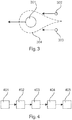
- FIG. 3 An example of a suitable beam shape for this purpose is in Fig. 3 shown.
- the main spot or main beam 301 is used to melt the material to be processed, and the two minor spots 302, 303 located laterally behind the main spot 301 serve to reduce the cooling gradient.
- the dashed line 304 indicates the area in which the material is liquid.
- the three laser spots move in the direction of the arrow to the left and come from the same laser source.
- Spatial light modulation can also be used to generate a beam profile, which is perceived as a line or spots 201, 202, 203, 204 arranged next to one another (cf. Fig. 2A ).
- the spots move, for example, perpendicular to their connecting line in the arrow direction down.
- optimal beam profiles can be provided and stored in the 3D printer or the welding device.
- the choice of the beam profile then takes place directly through the 3D printer or the welding device and thus remains independent of the so-called build processor. This saves considerable development effort on the build processor.
- Fig. 4 shows a flowchart of a method according to an embodiment of the invention.
- a laser beam is generated by a laser source.
- this laser beam is collimated and, in step 403, encounters a spatial light modulator that imposes spatial modulation on the laser beam to change the beam shape of the laser beam. For example, several separate laser beams can be generated from the one laser beam.
- the modified laser beam strikes the working plane. There is in the case of 3D printing a layer of the material to be processed or, in the case of the laser welding process, the weld to be produced.
- the Laser beam in the working plane moves to create a plane of the workpiece or to form the weld.
Landscapes
- Engineering & Computer Science (AREA)
- Chemical & Material Sciences (AREA)
- Materials Engineering (AREA)
- Manufacturing & Machinery (AREA)
- Physics & Mathematics (AREA)
- Plasma & Fusion (AREA)
- Optics & Photonics (AREA)
- Automation & Control Theory (AREA)
- Health & Medical Sciences (AREA)
- General Health & Medical Sciences (AREA)
- Toxicology (AREA)
- Mechanical Engineering (AREA)
- Powder Metallurgy (AREA)
Priority Applications (1)
| Application Number | Priority Date | Filing Date | Title |
|---|---|---|---|
| EP18154428.9A EP3520927B1 (fr) | 2018-01-31 | 2018-01-31 | Imprimante tridimensionnelle dotée d'un module de formage à commande électronique |
Applications Claiming Priority (1)
| Application Number | Priority Date | Filing Date | Title |
|---|---|---|---|
| EP18154428.9A EP3520927B1 (fr) | 2018-01-31 | 2018-01-31 | Imprimante tridimensionnelle dotée d'un module de formage à commande électronique |
Publications (2)
| Publication Number | Publication Date |
|---|---|
| EP3520927A1 true EP3520927A1 (fr) | 2019-08-07 |
| EP3520927B1 EP3520927B1 (fr) | 2020-07-29 |
Family
ID=61132162
Family Applications (1)
| Application Number | Title | Priority Date | Filing Date |
|---|---|---|---|
| EP18154428.9A Active EP3520927B1 (fr) | 2018-01-31 | 2018-01-31 | Imprimante tridimensionnelle dotée d'un module de formage à commande électronique |
Country Status (1)
| Country | Link |
|---|---|
| EP (1) | EP3520927B1 (fr) |
Cited By (1)
| Publication number | Priority date | Publication date | Assignee | Title |
|---|---|---|---|---|
| CN120269027A (zh) * | 2025-06-05 | 2025-07-08 | 中国科学院宁波材料技术与工程研究所 | 一种激光增材的铺粉层厚与光束整形协同调控系统及方法 |
Citations (7)
| Publication number | Priority date | Publication date | Assignee | Title |
|---|---|---|---|---|
| US20030052105A1 (en) * | 2001-09-10 | 2003-03-20 | Fuji Photo Film Co., Ltd. | Laser sintering apparatus |
| JP2003094185A (ja) * | 2001-09-25 | 2003-04-02 | Nippon Steel Corp | 亜鉛メッキ鋼板の重ねレーザ溶接方法および装置 |
| US20160243649A1 (en) * | 2014-07-10 | 2016-08-25 | Guangzhou Institute of Advanced Technology, Chinise Academy of Sciences | Optical system for 3d printing and control method thereof |
| WO2017015241A1 (fr) * | 2015-07-18 | 2017-01-26 | Vulcanforms Inc. | Fabrication additive par fusion de matériau spatialement contrôlée |
| US9636775B2 (en) * | 2014-12-24 | 2017-05-02 | Industrial Technology Research Institute | Composite beam generator and powder melting or sintering method using the same |
| EP3219412A1 (fr) * | 2014-11-14 | 2017-09-20 | Nikon Corporation | Dispositif et procédé de mise en forme |
| DE102016213420A1 (de) * | 2016-07-22 | 2018-01-25 | Robert Bosch Gmbh | Verfahren und Vorrichtung zum generativen Herstellen eines Bauteils |
Family Cites Families (1)
| Publication number | Priority date | Publication date | Assignee | Title |
|---|---|---|---|---|
| PL3180823T3 (pl) * | 2014-08-13 | 2022-08-08 | Ipg Photonics Corporation | System, sposób i zastosowanie wielowiązkowego lasera światłowodowego |
-
2018
- 2018-01-31 EP EP18154428.9A patent/EP3520927B1/fr active Active
Patent Citations (7)
| Publication number | Priority date | Publication date | Assignee | Title |
|---|---|---|---|---|
| US20030052105A1 (en) * | 2001-09-10 | 2003-03-20 | Fuji Photo Film Co., Ltd. | Laser sintering apparatus |
| JP2003094185A (ja) * | 2001-09-25 | 2003-04-02 | Nippon Steel Corp | 亜鉛メッキ鋼板の重ねレーザ溶接方法および装置 |
| US20160243649A1 (en) * | 2014-07-10 | 2016-08-25 | Guangzhou Institute of Advanced Technology, Chinise Academy of Sciences | Optical system for 3d printing and control method thereof |
| EP3219412A1 (fr) * | 2014-11-14 | 2017-09-20 | Nikon Corporation | Dispositif et procédé de mise en forme |
| US9636775B2 (en) * | 2014-12-24 | 2017-05-02 | Industrial Technology Research Institute | Composite beam generator and powder melting or sintering method using the same |
| WO2017015241A1 (fr) * | 2015-07-18 | 2017-01-26 | Vulcanforms Inc. | Fabrication additive par fusion de matériau spatialement contrôlée |
| DE102016213420A1 (de) * | 2016-07-22 | 2018-01-25 | Robert Bosch Gmbh | Verfahren und Vorrichtung zum generativen Herstellen eines Bauteils |
Non-Patent Citations (1)
| Title |
|---|
| POHL R ET AL: "Solid-phase laser-induced forward transfer of variable shapes using a liquid-crystal spatial light modulator", APPLIED PHYSICS A MATERIALS SCIENCE & PROCESSING, SPRINGER BERLIN HEIDELBERG, BERLIN/HEIDELBERG, vol. 120, no. 2, 12 May 2015 (2015-05-12), pages 427 - 434, XP035516347, ISSN: 0947-8396, [retrieved on 20150512], DOI: 10.1007/S00339-015-9212-2 * |
Cited By (1)
| Publication number | Priority date | Publication date | Assignee | Title |
|---|---|---|---|---|
| CN120269027A (zh) * | 2025-06-05 | 2025-07-08 | 中国科学院宁波材料技术与工程研究所 | 一种激光增材的铺粉层厚与光束整形协同调控系统及方法 |
Also Published As
| Publication number | Publication date |
|---|---|
| EP3520927B1 (fr) | 2020-07-29 |
Similar Documents
| Publication | Publication Date | Title |
|---|---|---|
| DE112014001710B4 (de) | Laserbearbeitungsvorrichtung und Laserbearbeitungsverfahren | |
| DE112014001688B4 (de) | Laserbearbeitungsvorrichtung und Laserbearbeitungsverfahren | |
| EP3221727B1 (fr) | Système de formage par faisceau optique asymétrique | |
| EP2335848B1 (fr) | Unité de rayonnement optique pour une installation destinée à la fabrication de pièces à usiner par rayonnement de couches de pulvérisation avec un rayonnement laser | |
| DE112014001653B4 (de) | Laserbearbeitungsvorrichtung und Laserbearbeitungsverfahren | |
| WO2016079063A1 (fr) | Élément optique diffractif de mise en forme de faisceau | |
| EP3256285A1 (fr) | Dispositif d'irradiation, machine de traitement et procédé de fabrication d'une couche ou d'une sous-zone d'une couche d'une pièce tridimensionnelle | |
| DE102014203025A1 (de) | Verfahren zum Laserstrahlschweißen und Schweißkopf | |
| WO2018219710A1 (fr) | Procédé de soudage profond d'une pièce comportant une répartition de la puissance laser à plusieurs foyers | |
| DE112014001676T5 (de) | Laserbearbeitungsvorrichtung und laserbearbeitungsverfahren | |
| DE102006042280A1 (de) | Bearbeitung von transparentem Material mit einem Ultrakurzpuls-Laser | |
| EP3880398B1 (fr) | Procédé de soudage sans éclaboussures, notamment avec un laser à l'état solide | |
| DE102019125103A1 (de) | Bearbeitungsvorrichtung zur Laserbearbeitung eines Werkstücks, Verfahren zur Laserbearbeitung eines Werkstücks | |
| DE102010007323A1 (de) | Verfahren zum Bestimmen des Schneidergebnisses eines Laserschneidprozesses | |
| DE102014201715A1 (de) | Verfahren und Vorrichtung zum Punktschweißen von Werkstücken mittels Laserpulsen mit grüner Wellenlänge | |
| DE102022112212A1 (de) | Technik zum Erzeugen einer Kantenverrundung | |
| DE102013011675A1 (de) | Verfahren zur generativen Bauteilfertigung mit reduzierten thermischen Gradienten | |
| EP3346314A1 (fr) | Dispositif et procédé de génération d'un faisceau laser à l'aide d'un dispositif générateur de faisceau programmable | |
| DE102021126754A1 (de) | Verfahren zum Laserschweißen eines Werkstücks mit schnellem Wechsel zwischen Schweißzonen mit unterschiedlichen zu schweißenden Materialien | |
| DE102016213420A1 (de) | Verfahren und Vorrichtung zum generativen Herstellen eines Bauteils | |
| WO2020254639A1 (fr) | Procédé et dispositif pour l'usinage d'une pièce avec composition du faisceau d'usinage à partir d'au moins deux profils de faisceau | |
| DE102015212284A1 (de) | Vorrichtung und Verfahren zum pulverbasierten Laser-Auftragsschweißen | |
| EP3520927B1 (fr) | Imprimante tridimensionnelle dotée d'un module de formage à commande électronique | |
| DE102022101092A1 (de) | Verfahren zur Laserbearbeitung eines Werkstücks mit verringerter Intensitätslücke | |
| EP3986660B1 (fr) | Procédé et dispositif de soudage d'une pièce transparente à une autre pièce, avec modulation de l'énergie du faisceau laser dans la zone de soudage |
Legal Events
| Date | Code | Title | Description |
|---|---|---|---|
| PUAI | Public reference made under article 153(3) epc to a published international application that has entered the european phase |
Free format text: ORIGINAL CODE: 0009012 |
|
| STAA | Information on the status of an ep patent application or granted ep patent |
Free format text: STATUS: REQUEST FOR EXAMINATION WAS MADE |
|
| 17P | Request for examination filed |
Effective date: 20190124 |
|
| AK | Designated contracting states |
Kind code of ref document: A1 Designated state(s): AL AT BE BG CH CY CZ DE DK EE ES FI FR GB GR HR HU IE IS IT LI LT LU LV MC MK MT NL NO PL PT RO RS SE SI SK SM TR |
|
| AX | Request for extension of the european patent |
Extension state: BA ME |
|
| STAA | Information on the status of an ep patent application or granted ep patent |
Free format text: STATUS: EXAMINATION IS IN PROGRESS |
|
| 17Q | First examination report despatched |
Effective date: 20190923 |
|
| RIC1 | Information provided on ipc code assigned before grant |
Ipc: B22F 7/06 20060101ALI20200109BHEP Ipc: B29C 64/153 20170101ALI20200109BHEP Ipc: B22F 3/105 20060101AFI20200109BHEP Ipc: B22F 7/08 20060101ALI20200109BHEP Ipc: B33Y 10/00 20150101ALI20200109BHEP |
|
| GRAP | Despatch of communication of intention to grant a patent |
Free format text: ORIGINAL CODE: EPIDOSNIGR1 |
|
| STAA | Information on the status of an ep patent application or granted ep patent |
Free format text: STATUS: GRANT OF PATENT IS INTENDED |
|
| INTG | Intention to grant announced |
Effective date: 20200218 |
|
| GRAS | Grant fee paid |
Free format text: ORIGINAL CODE: EPIDOSNIGR3 |
|
| GRAA | (expected) grant |
Free format text: ORIGINAL CODE: 0009210 |
|
| STAA | Information on the status of an ep patent application or granted ep patent |
Free format text: STATUS: THE PATENT HAS BEEN GRANTED |
|
| AK | Designated contracting states |
Kind code of ref document: B1 Designated state(s): AL AT BE BG CH CY CZ DE DK EE ES FI FR GB GR HR HU IE IS IT LI LT LU LV MC MK MT NL NO PL PT RO RS SE SI SK SM TR |
|
| REG | Reference to a national code |
Ref country code: CH Ref legal event code: EP |
|
| REG | Reference to a national code |
Ref country code: AT Ref legal event code: REF Ref document number: 1295208 Country of ref document: AT Kind code of ref document: T Effective date: 20200815 |
|
| REG | Reference to a national code |
Ref country code: IE Ref legal event code: FG4D Free format text: LANGUAGE OF EP DOCUMENT: GERMAN |
|
| REG | Reference to a national code |
Ref country code: DE Ref legal event code: R096 Ref document number: 502018001971 Country of ref document: DE |
|
| REG | Reference to a national code |
Ref country code: CH Ref legal event code: NV Representative=s name: ING. MARCO ZARDI C/O M. ZARDI AND CO. S.A., CH |
|
| REG | Reference to a national code |
Ref country code: LT Ref legal event code: MG4D |
|
| REG | Reference to a national code |
Ref country code: NL Ref legal event code: MP Effective date: 20200729 |
|
| PG25 | Lapsed in a contracting state [announced via postgrant information from national office to epo] |
Ref country code: BG Free format text: LAPSE BECAUSE OF FAILURE TO SUBMIT A TRANSLATION OF THE DESCRIPTION OR TO PAY THE FEE WITHIN THE PRESCRIBED TIME-LIMIT Effective date: 20201029 Ref country code: NO Free format text: LAPSE BECAUSE OF FAILURE TO SUBMIT A TRANSLATION OF THE DESCRIPTION OR TO PAY THE FEE WITHIN THE PRESCRIBED TIME-LIMIT Effective date: 20201029 Ref country code: GR Free format text: LAPSE BECAUSE OF FAILURE TO SUBMIT A TRANSLATION OF THE DESCRIPTION OR TO PAY THE FEE WITHIN THE PRESCRIBED TIME-LIMIT Effective date: 20201030 Ref country code: LT Free format text: LAPSE BECAUSE OF FAILURE TO SUBMIT A TRANSLATION OF THE DESCRIPTION OR TO PAY THE FEE WITHIN THE PRESCRIBED TIME-LIMIT Effective date: 20200729 Ref country code: HR Free format text: LAPSE BECAUSE OF FAILURE TO SUBMIT A TRANSLATION OF THE DESCRIPTION OR TO PAY THE FEE WITHIN THE PRESCRIBED TIME-LIMIT Effective date: 20200729 Ref country code: PT Free format text: LAPSE BECAUSE OF FAILURE TO SUBMIT A TRANSLATION OF THE DESCRIPTION OR TO PAY THE FEE WITHIN THE PRESCRIBED TIME-LIMIT Effective date: 20201130 Ref country code: SE Free format text: LAPSE BECAUSE OF FAILURE TO SUBMIT A TRANSLATION OF THE DESCRIPTION OR TO PAY THE FEE WITHIN THE PRESCRIBED TIME-LIMIT Effective date: 20200729 Ref country code: FI Free format text: LAPSE BECAUSE OF FAILURE TO SUBMIT A TRANSLATION OF THE DESCRIPTION OR TO PAY THE FEE WITHIN THE PRESCRIBED TIME-LIMIT Effective date: 20200729 Ref country code: ES Free format text: LAPSE BECAUSE OF FAILURE TO SUBMIT A TRANSLATION OF THE DESCRIPTION OR TO PAY THE FEE WITHIN THE PRESCRIBED TIME-LIMIT Effective date: 20200729 |
|
| PG25 | Lapsed in a contracting state [announced via postgrant information from national office to epo] |
Ref country code: IS Free format text: LAPSE BECAUSE OF FAILURE TO SUBMIT A TRANSLATION OF THE DESCRIPTION OR TO PAY THE FEE WITHIN THE PRESCRIBED TIME-LIMIT Effective date: 20201129 Ref country code: PL Free format text: LAPSE BECAUSE OF FAILURE TO SUBMIT A TRANSLATION OF THE DESCRIPTION OR TO PAY THE FEE WITHIN THE PRESCRIBED TIME-LIMIT Effective date: 20200729 Ref country code: RS Free format text: LAPSE BECAUSE OF FAILURE TO SUBMIT A TRANSLATION OF THE DESCRIPTION OR TO PAY THE FEE WITHIN THE PRESCRIBED TIME-LIMIT Effective date: 20200729 Ref country code: LV Free format text: LAPSE BECAUSE OF FAILURE TO SUBMIT A TRANSLATION OF THE DESCRIPTION OR TO PAY THE FEE WITHIN THE PRESCRIBED TIME-LIMIT Effective date: 20200729 |
|
| PG25 | Lapsed in a contracting state [announced via postgrant information from national office to epo] |
Ref country code: NL Free format text: LAPSE BECAUSE OF FAILURE TO SUBMIT A TRANSLATION OF THE DESCRIPTION OR TO PAY THE FEE WITHIN THE PRESCRIBED TIME-LIMIT Effective date: 20200729 |
|
| PG25 | Lapsed in a contracting state [announced via postgrant information from national office to epo] |
Ref country code: SM Free format text: LAPSE BECAUSE OF FAILURE TO SUBMIT A TRANSLATION OF THE DESCRIPTION OR TO PAY THE FEE WITHIN THE PRESCRIBED TIME-LIMIT Effective date: 20200729 Ref country code: RO Free format text: LAPSE BECAUSE OF FAILURE TO SUBMIT A TRANSLATION OF THE DESCRIPTION OR TO PAY THE FEE WITHIN THE PRESCRIBED TIME-LIMIT Effective date: 20200729 Ref country code: DK Free format text: LAPSE BECAUSE OF FAILURE TO SUBMIT A TRANSLATION OF THE DESCRIPTION OR TO PAY THE FEE WITHIN THE PRESCRIBED TIME-LIMIT Effective date: 20200729 Ref country code: CZ Free format text: LAPSE BECAUSE OF FAILURE TO SUBMIT A TRANSLATION OF THE DESCRIPTION OR TO PAY THE FEE WITHIN THE PRESCRIBED TIME-LIMIT Effective date: 20200729 Ref country code: EE Free format text: LAPSE BECAUSE OF FAILURE TO SUBMIT A TRANSLATION OF THE DESCRIPTION OR TO PAY THE FEE WITHIN THE PRESCRIBED TIME-LIMIT Effective date: 20200729 Ref country code: IT Free format text: LAPSE BECAUSE OF FAILURE TO SUBMIT A TRANSLATION OF THE DESCRIPTION OR TO PAY THE FEE WITHIN THE PRESCRIBED TIME-LIMIT Effective date: 20200729 |
|
| REG | Reference to a national code |
Ref country code: DE Ref legal event code: R097 Ref document number: 502018001971 Country of ref document: DE |
|
| PG25 | Lapsed in a contracting state [announced via postgrant information from national office to epo] |
Ref country code: AL Free format text: LAPSE BECAUSE OF FAILURE TO SUBMIT A TRANSLATION OF THE DESCRIPTION OR TO PAY THE FEE WITHIN THE PRESCRIBED TIME-LIMIT Effective date: 20200729 |
|
| PLBE | No opposition filed within time limit |
Free format text: ORIGINAL CODE: 0009261 |
|
| STAA | Information on the status of an ep patent application or granted ep patent |
Free format text: STATUS: NO OPPOSITION FILED WITHIN TIME LIMIT |
|
| PG25 | Lapsed in a contracting state [announced via postgrant information from national office to epo] |
Ref country code: SK Free format text: LAPSE BECAUSE OF FAILURE TO SUBMIT A TRANSLATION OF THE DESCRIPTION OR TO PAY THE FEE WITHIN THE PRESCRIBED TIME-LIMIT Effective date: 20200729 |
|
| 26N | No opposition filed |
Effective date: 20210430 |
|
| PG25 | Lapsed in a contracting state [announced via postgrant information from national office to epo] |
Ref country code: SI Free format text: LAPSE BECAUSE OF FAILURE TO SUBMIT A TRANSLATION OF THE DESCRIPTION OR TO PAY THE FEE WITHIN THE PRESCRIBED TIME-LIMIT Effective date: 20200729 Ref country code: MC Free format text: LAPSE BECAUSE OF FAILURE TO SUBMIT A TRANSLATION OF THE DESCRIPTION OR TO PAY THE FEE WITHIN THE PRESCRIBED TIME-LIMIT Effective date: 20200729 |
|
| PG25 | Lapsed in a contracting state [announced via postgrant information from national office to epo] |
Ref country code: LU Free format text: LAPSE BECAUSE OF NON-PAYMENT OF DUE FEES Effective date: 20210131 |
|
| PG25 | Lapsed in a contracting state [announced via postgrant information from national office to epo] |
Ref country code: IE Free format text: LAPSE BECAUSE OF NON-PAYMENT OF DUE FEES Effective date: 20210131 |
|
| P01 | Opt-out of the competence of the unified patent court (upc) registered |
Effective date: 20230504 |
|
| PG25 | Lapsed in a contracting state [announced via postgrant information from national office to epo] |
Ref country code: CY Free format text: LAPSE BECAUSE OF FAILURE TO SUBMIT A TRANSLATION OF THE DESCRIPTION OR TO PAY THE FEE WITHIN THE PRESCRIBED TIME-LIMIT Effective date: 20200729 |
|
| PG25 | Lapsed in a contracting state [announced via postgrant information from national office to epo] |
Ref country code: HU Free format text: LAPSE BECAUSE OF FAILURE TO SUBMIT A TRANSLATION OF THE DESCRIPTION OR TO PAY THE FEE WITHIN THE PRESCRIBED TIME-LIMIT; INVALID AB INITIO Effective date: 20180131 |
|
| REG | Reference to a national code |
Ref country code: AT Ref legal event code: MM01 Ref document number: 1295208 Country of ref document: AT Kind code of ref document: T Effective date: 20230131 |
|
| PG25 | Lapsed in a contracting state [announced via postgrant information from national office to epo] |
Ref country code: AT Free format text: LAPSE BECAUSE OF NON-PAYMENT OF DUE FEES Effective date: 20230131 |
|
| PG25 | Lapsed in a contracting state [announced via postgrant information from national office to epo] |
Ref country code: MK Free format text: LAPSE BECAUSE OF FAILURE TO SUBMIT A TRANSLATION OF THE DESCRIPTION OR TO PAY THE FEE WITHIN THE PRESCRIBED TIME-LIMIT Effective date: 20200729 Ref country code: AT Free format text: LAPSE BECAUSE OF NON-PAYMENT OF DUE FEES Effective date: 20230131 |
|
| PG25 | Lapsed in a contracting state [announced via postgrant information from national office to epo] |
Ref country code: MT Free format text: LAPSE BECAUSE OF FAILURE TO SUBMIT A TRANSLATION OF THE DESCRIPTION OR TO PAY THE FEE WITHIN THE PRESCRIBED TIME-LIMIT Effective date: 20200729 |
|
| PG25 | Lapsed in a contracting state [announced via postgrant information from national office to epo] |
Ref country code: TR Free format text: LAPSE BECAUSE OF FAILURE TO SUBMIT A TRANSLATION OF THE DESCRIPTION OR TO PAY THE FEE WITHIN THE PRESCRIBED TIME-LIMIT Effective date: 20200729 |
|
| REG | Reference to a national code |
Ref country code: CH Ref legal event code: U11 Free format text: ST27 STATUS EVENT CODE: U-0-0-U10-U11 (AS PROVIDED BY THE NATIONAL OFFICE) Effective date: 20260201 |
|
| PGFP | Annual fee paid to national office [announced via postgrant information from national office to epo] |
Ref country code: GB Payment date: 20260122 Year of fee payment: 9 |
|
| PGFP | Annual fee paid to national office [announced via postgrant information from national office to epo] |
Ref country code: DE Payment date: 20260129 Year of fee payment: 9 |
|
| PGFP | Annual fee paid to national office [announced via postgrant information from national office to epo] |
Ref country code: AT Payment date: 20260410 Year of fee payment: 5 |
|
| PGFP | Annual fee paid to national office [announced via postgrant information from national office to epo] |
Ref country code: BE Payment date: 20260121 Year of fee payment: 9 |
|
| PGFP | Annual fee paid to national office [announced via postgrant information from national office to epo] |
Ref country code: FR Payment date: 20260121 Year of fee payment: 9 |
|
| PGFP | Annual fee paid to national office [announced via postgrant information from national office to epo] |
Ref country code: CH Payment date: 20260201 Year of fee payment: 9 |