EP3520945B1 - Procédé de brasage laser - Google Patents
Procédé de brasage laser Download PDFInfo
- Publication number
- EP3520945B1 EP3520945B1 EP18155157.3A EP18155157A EP3520945B1 EP 3520945 B1 EP3520945 B1 EP 3520945B1 EP 18155157 A EP18155157 A EP 18155157A EP 3520945 B1 EP3520945 B1 EP 3520945B1
- Authority
- EP
- European Patent Office
- Prior art keywords
- range
- specifically
- laser
- laser beam
- process according
- Prior art date
- Legal status (The legal status is an assumption and is not a legal conclusion. Google has not performed a legal analysis and makes no representation as to the accuracy of the status listed.)
- Active
Links
Images


Classifications
-
- B—PERFORMING OPERATIONS; TRANSPORTING
- B23—MACHINE TOOLS; METAL-WORKING NOT OTHERWISE PROVIDED FOR
- B23K—SOLDERING OR UNSOLDERING; WELDING; CLADDING OR PLATING BY SOLDERING OR WELDING; CUTTING BY APPLYING HEAT LOCALLY, e.g. FLAME CUTTING; WORKING BY LASER BEAM
- B23K1/00—Soldering, e.g. brazing, or unsoldering
- B23K1/005—Soldering by means of radiant energy
- B23K1/0056—Soldering by means of radiant energy soldering by means of beams, e.g. lasers, electron beams [EB]
-
- B—PERFORMING OPERATIONS; TRANSPORTING
- B23—MACHINE TOOLS; METAL-WORKING NOT OTHERWISE PROVIDED FOR
- B23K—SOLDERING OR UNSOLDERING; WELDING; CLADDING OR PLATING BY SOLDERING OR WELDING; CUTTING BY APPLYING HEAT LOCALLY, e.g. FLAME CUTTING; WORKING BY LASER BEAM
- B23K1/00—Soldering, e.g. brazing, or unsoldering
- B23K1/0008—Soldering, e.g. brazing, or unsoldering specially adapted for particular articles or work
-
- B—PERFORMING OPERATIONS; TRANSPORTING
- B23—MACHINE TOOLS; METAL-WORKING NOT OTHERWISE PROVIDED FOR
- B23K—SOLDERING OR UNSOLDERING; WELDING; CLADDING OR PLATING BY SOLDERING OR WELDING; CUTTING BY APPLYING HEAT LOCALLY, e.g. FLAME CUTTING; WORKING BY LASER BEAM
- B23K1/00—Soldering, e.g. brazing, or unsoldering
- B23K1/19—Soldering, e.g. brazing, or unsoldering taking account of the properties of the materials to be soldered
-
- B—PERFORMING OPERATIONS; TRANSPORTING
- B23—MACHINE TOOLS; METAL-WORKING NOT OTHERWISE PROVIDED FOR
- B23K—SOLDERING OR UNSOLDERING; WELDING; CLADDING OR PLATING BY SOLDERING OR WELDING; CUTTING BY APPLYING HEAT LOCALLY, e.g. FLAME CUTTING; WORKING BY LASER BEAM
- B23K26/00—Working by laser beam, e.g. welding, cutting or boring
- B23K26/02—Positioning or observing the workpiece, e.g. with respect to the point of impact; Aligning, aiming or focusing the laser beam
- B23K26/06—Shaping the laser beam, e.g. by masks or multi-focusing
- B23K26/064—Shaping the laser beam, e.g. by masks or multi-focusing by means of optical elements, e.g. lenses, mirrors or prisms
- B23K26/0648—Shaping the laser beam, e.g. by masks or multi-focusing by means of optical elements, e.g. lenses, mirrors or prisms comprising lenses
-
- B—PERFORMING OPERATIONS; TRANSPORTING
- B23—MACHINE TOOLS; METAL-WORKING NOT OTHERWISE PROVIDED FOR
- B23K—SOLDERING OR UNSOLDERING; WELDING; CLADDING OR PLATING BY SOLDERING OR WELDING; CUTTING BY APPLYING HEAT LOCALLY, e.g. FLAME CUTTING; WORKING BY LASER BEAM
- B23K26/00—Working by laser beam, e.g. welding, cutting or boring
- B23K26/08—Devices involving relative movement between laser beam and workpiece
- B23K26/0869—Devices involving movement of the laser head in at least one axial direction
- B23K26/0876—Devices involving movement of the laser head in at least one axial direction in at least two axial directions
- B23K26/0884—Devices involving movement of the laser head in at least one axial direction in at least two axial directions in at least three axial directions, e.g. manipulators, robots
-
- B—PERFORMING OPERATIONS; TRANSPORTING
- B23—MACHINE TOOLS; METAL-WORKING NOT OTHERWISE PROVIDED FOR
- B23K—SOLDERING OR UNSOLDERING; WELDING; CLADDING OR PLATING BY SOLDERING OR WELDING; CUTTING BY APPLYING HEAT LOCALLY, e.g. FLAME CUTTING; WORKING BY LASER BEAM
- B23K35/00—Rods, electrodes, materials, or media, for use in soldering, welding, or cutting
- B23K35/22—Rods, electrodes, materials, or media, for use in soldering, welding, or cutting characterised by the composition or nature of the material
- B23K35/24—Selection of soldering or welding materials proper
- B23K35/30—Selection of soldering or welding materials proper with the principal constituent melting at less than 1550°C
- B23K35/302—Cu as the principal constituent
-
- B—PERFORMING OPERATIONS; TRANSPORTING
- B23—MACHINE TOOLS; METAL-WORKING NOT OTHERWISE PROVIDED FOR
- B23K—SOLDERING OR UNSOLDERING; WELDING; CLADDING OR PLATING BY SOLDERING OR WELDING; CUTTING BY APPLYING HEAT LOCALLY, e.g. FLAME CUTTING; WORKING BY LASER BEAM
- B23K2101/00—Articles made by soldering, welding or cutting
- B23K2101/006—Vehicles
-
- B—PERFORMING OPERATIONS; TRANSPORTING
- B23—MACHINE TOOLS; METAL-WORKING NOT OTHERWISE PROVIDED FOR
- B23K—SOLDERING OR UNSOLDERING; WELDING; CLADDING OR PLATING BY SOLDERING OR WELDING; CUTTING BY APPLYING HEAT LOCALLY, e.g. FLAME CUTTING; WORKING BY LASER BEAM
- B23K2103/00—Materials to be soldered, welded or cut
- B23K2103/02—Iron or ferrous alloys
- B23K2103/04—Steel or steel alloys
Definitions
- the disclosure relates to a process for joining a first metal workpiece and a second metal workpiece by laser brazing for forming a vehicle structure, see claim 1.
- the process according to the disclosure is thus particularly suitable for laser brazing of a vehicle roof panel to vehicle side panel.
- the disclosure will be described primarily in relation to mutual joining of a roof panel and a side panel the disclosure is not restricted to this particular application, but may alternatively be used for joining other metal workpieces of a vehicle.
- a general object of the present disclosure is to provide an improved process for joining a first metal workpiece and a second metal workpiece by laser brazing for forming a vehicle structure.
- an object of the present disclosure is to provide a manufacturing process where the laser brazing production speed is increased with maintained high-quality joint quality.
- Still a further object of the present disclosure is to provide a manufacturing process for joining two metal workpieces by laser brazing where at least one of the first and second metal workpieces is made of hot-dip galvanized steel material.
- Hot-dip galvanized steel material typically has a thicker zinc coating than a conventional electro-galvanization steel material.
- the process for joining a first metal workpiece and a second metal workpiece by laser brazing for forming a vehicle structure comprises providing the first metal workpiece and the second metal workpiece in contacting relationship so as to form an elongated contact region, wherein at least one of the metal workpieces is made of hot-dip galvanized steel material, supplying a laser beam having a beam parameter product lower than 10 millimetre times milliradians (mm ⁇ mrad) from a laser source, guiding the laser beam through a laser focus head having a total optical magnification in the range of 1:0.5 - 1:1.5, directing the laser beam along the elongated contact region, wherein a beam spot formed where the laser beam hits the contact region has a size in the range of 2 - 6 mm (millimetres), and supplying a consumable wire of filler material to the beam spot to melt the consumable wire and braze said two metal workpieces together, wherein the consumable wire comprises at least 95% copper.
- Galvanization is the process of applying a protective zinc coating to steel metal sheet to increased corrosion resistance.
- various galvanization processes available.
- the roof panel and side panel of a vehicle have been galvanized by a process called electro-galvanization because this process is characterised by producing a relatively thin zinc coating layer on the steel metal sheets, such as for example in the range of 0.1 - 0.5 ⁇ m (micrometres), and this was desirable because it enabled laser brazing joining of the metal workpieces.
- An electrogalvanized coating is created by applying zinc to steel sheet by electrodeposition. This is for example performed by submerging the metal workpiece into a zinc plating bath, in which a zinc coating develops as positively charged zinc ions in the bath are electrically reduced to zinc metal and deposited on the positively charged metal workpiece.
- Hot-dip galvanizing is a faster process and produces a thicker zinc coating layer on the metal workpieces compared with the electro-galvanization process.
- the resulting zinc coating thickness may for example be in the range of 3 - 5 ⁇ m.
- This set-up enables laser brazing of hot-dip galvanized metal workpieces a relatively high process speed of about 3.5 - 6.5 metres per minute and with a resulting laser brazing joint that has substantially no spatter and no pores, such that the need for post-processing of the finished joint, such as grinding or polishing, is eliminated.
- the laser beam has a beam parameter product not higher than 8 mm ⁇ mrad, and specifically in the range of 2 - 8 mm ⁇ mrad.
- the Beam Parameter Product quantifies the quality of a laser beam and how well it can be focused to a small spot.
- a relatively low beam parameter product consequently enables use of a relatively small diameter fibre optic cable without losing too much of the laser power at the entrance of the fibre optic cable, because the focused spot should be comparable to the core size to obtain good coupling efficiency into the fibre optic cable.
- the laser focus head has a total optical magnification in the range of 1:0.7 - 1:1.3, and specifically in the range of 1:0.9 - 1:1.1.
- a total optical magnification not too far away from 1:1 results in a more or less Gaussian laser power distribution at the beam spot, and the extensive research and experimental laser brazing testing for finding appropriate process parameters has surprisingly revealed that a Gaussian laser power distribution at the beam spot improves the quality of the laser brazing joint and enables relatively high process speeds.
- a magnification level of about 1:1 also has the advantage of enabling also laser welding by means of the same laser equipment.
- this type of magnification enables dual use of the same laser equipment. This is very attractive for manufacturing companies because they can then use substantially the same laser equipment for two different manufacturing processes for increased flexibility.
- the use of the same type of laser equipment for both laser brazing and laser welding results in less need for different types of replacement parts, service partners, etc.
- the beam spot has a size in the range of 3 - 5 mm.
- the extensive research and experimental laser brazing testing for finding appropriate process parameters has revealed that a beam spot size in the range of 3 - 5 mm results in even less spatter and pores formation while allowing a high process speed.
- the extensive research and experimental laser brazing testing for finding appropriate process parameters has surprisingly revealed that further improved laser brazing result in terms of reduced spatter and pores formation and high process speed can be obtained if the consumable wire comprises at least 96% copper, and specifically at least 96.5% copper.
- the at least one metal workpiece made of hot-dip galvanized steel material has a zinc coating in the range of 25 - 95 g/m 2 (grams per square metre), specifically in the range of 35 - 75 g/m 2 , and more specifically in the range of 40 - 60 g/m 2 .
- Hot-dip galvanized steel has a relatively large zinc coating thickness compared with electrogalvanized coating and thereby offers an improved corrosion resistance.
- the at least one metal workpiece made of hot-dip galvanized steel material is a sheet steel with a thickness in the range of 0.3 - 1.0 mm, specifically in the range of 0.4 - 0.8 mm, and more specifically in the range of 0.5 - 0.7 mm.
- the consumable wire comprises less than 3% silicon, specifically less than 2.5% silicon, and more specifically 1 - 2.5% silicon.
- the extensive research and experimental laser brazing testing for finding appropriate process parameters has revealed that the consumable wire shall comprises less than 3% silicon, specifically less than 2.5% silicon, and more specifically 1 - 2.5% silicon, in order to provide the desired high quality laser brazing seam and high process speed.
- the consumable wire is of the type ISO 24373; Cu 6511 CuSi2Mn1.
- This particular type of consumable wire is a copper-silicon-manganese wire that has displayed very good results in terms desired high quality laser brazing seam and high process speed in combination with hot-dip galvanized sheet steel.
- the typical composition (weight %) of this wire is: Silicon (Si) Tin (Sn) Manganese (Mn) Copper (CU) 1.7 - 1.9% 0.17-0,25% 0.9 - 1.1% Rest
- the laser beam at the output of the laser source has a power of at least 2.5 kW, specifically at least 3.5 kW, and more specifically in the range of 3.5 - 10 kW.
- the extensive research and testing has showed that at laser power of at least 2.5 kW is necessary to accomplish the desired relatively high process speed. Moreover, further increased process speed is possible with increased laser power without any significant reduction on laser brazing quality.
- the laser beam at the output of the laser source has a wavelength in the range of 800-1200 nm, and specifically in the range of 900-1100 nm. This type of wavelength has proven to enable the desired high process speed and laser bracing quality.
- the process comprises guiding the laser beam from the laser source to the laser focus head through a fibre optic cable having a central core diameter of not more than 1 mm, specifically not more than 0.6 mm, and more specifically in the range of 0.2 - 0.6 mm.
- the central core diameter determines the minimum beam spot size at the work piece and is thus a relevant parameter for accomplishing a high quality and high speed laser brazing process.
- this relatively high process speed has significant effect on the cost for manufacturing a vehicle since the elongated contact region to be joined using laser brazing between the roof panel and side panel is relatively long, and the total process time for producing the laser brazing seam at both lateral sides of the roof can therefore be significantly reduced for improved productivity.
- the process comprising supplying the consumable wire with a wire feeding rate of 50-100% of the process speed, and specifically 70-90% of the process speed.
- the consumable wire has a wire diameter in the range of 0.8 - 2.4 mm, specifically in the range of 1.0 - 1.8 mm, and more specifically in the range of 1.2 - 1.6 mm.
- This wire feeding rate results in the desired high quality and high speed laser brazing process.
- a laser beam process direction angle between the laser beam and an outer surface of the first or second metal workpiece, in the process direction, at the beam spot is in the range of 60-90 degrees, specifically in the range of 65-85 degrees, and more specifically in the range of 70-83 degrees.
- a longitudinal axis of the filler wire adjacent the beam spot leans more forward in the process direction than a direction of the laser beam at the beam spot, and wherein a feed angle between the laser beam and the longitudinal axis of the consumable wire, in the process direction, adjacent the beam spot, is in the range of 10-50 degrees, and specifically in the range of 20-40 degrees.
- one of the first and second metal workpieces is a vehicle roof panel and that the other metal workpiece is a vehicle side panel.
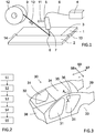
- Figure 1 schematically depicts a process for joining a first metal workpiece 1 and a second metal workpiece 2 by laser brazing for forming a vehicle structure.
- the first and second metal workpieces 1, 2 are provided in contacting relationship so as to form an elongated contact region 3.
- at least one of the metal workpieces 1, 2 is made of hot-dip galvanized steel material.
- a laser source 4 supplies a laser beam to a laser focus head 5 via a fibre optic cable 6, and a focused single laser beam 7 is directed to the contact region 3.
- the laser focus head 5 is of a monofocus type, i.e. it supplies a single laser beam.
- a single beam spot 8 is consequently formed where the laser beam hits the contact region and a consumable wire 9 of filler material is simultaneously supplied to the beam spot along feed direction 10.
- the heat of the laser beam 7 melts the consumable wire 9 when supplied to the beam spot and the melted filler material penetrates into the gap in the joint between the first and second metal workpieces 1, 2 and wets the joint surfaces.
- the laser beam spot 8 As soon as the laser beam spot 8 has moved past an area of melted filler material the melted filler material directly starts to cool down and subsequently solidify to form a smooth joint with high joint surface quality, high joint corrosion resistance and low or no need for refinishing work.
- the process comprises a first step S1 of providing the first metal workpiece 1 and the second metal workpiece 2 in contacting relationship so as to form an elongated contact region 3, wherein one of both of the metal workpieces 1, 2 are made of hot-dip galvanized steel material.
- Hot-dip galvanized steel material is a steel material that has been galvanized in a hot-dip galvanizing process. This is typically performed by first cleaning the steel material, such as sheet steel, and subsequently submerging the steep material in a bath of molten zinc. Hot-dip galvanization is a relatively fast process that produces a relatively thick zinc coating layer on the steel material, such as for example in the range of 3 - 5 ⁇ m.
- a metal workpiece made of hot-dip galvanized steel material typically has a zinc coating in the range of 25 - 95 g/m 2 , specifically in the range of 35 - 75 g/m 2 , and more specifically in the range of 40 - 60 g/m 2 .
- a second step S2 of the process for joining the first and second metal workpieces 1, 2 by laser brazing comprises supplying a laser beam having a beam parameter product (BPP) lower than 10 mm ⁇ mrad from the laser source 4.
- BPP beam parameter product
- the laser beam may have a beam parameter product (BPP) not higher than 8 mm ⁇ mrad, and more specifically in the range of 2 - 8 mm ⁇ mrad.
- BPP beam parameter product
- the beam parameter product (BPP) of a laser beam is defined as the product of beam radius (measured at the beam waist) and the beam divergence half-angle (measured in the far field).
- the usual units are mm x mrad (millimetres multiplied with milliradians).
- the BPP is often used to specify the beam quality of a laser beam: the higher the beam parameter product, the lower is the beam quality.
- the laser beam supplied at the output of the laser source 4 may for example have a power of at least 2.5 kW, specifically at least 3.5 kW, and more specifically in the range of 3.5 - 10 kW. Generally, increased power level of the laser beam enables higher production speed.
- the laser beam at the output of the laser source 4 may for example have a wavelength in the range of 800-1200 nm, and specifically in the range of 900-1100 nm.
- a third step S3 of the process for joining the first and second metal workpieces by laser brazing comprises guiding the laser beam through the laser focus head 5, which has a total optical magnification in the range of 1:0.5 - 1:1.5.
- the laser focus head may alternatively have a total optical magnification in the range of 1:0.7 - 1:1.3, and specifically in the range of 1:0.9 - 1:1.1.
- the total optical magnification of a laser focus head 5 is determined by the ratio between the total focal length of the laser head's collimating lens arrangement and focus lens arrangement, as will be described more in detail below with reference to figure 7 .
- a fourth step S4 of the process for joining the first and second metal workpieces 1, 2 by laser brazing comprises directing the laser beam 7 along the elongated contact region 3.
- a beam spot 8 is formed where the laser beam 7 hits the contact region has a size in the range of 2 - 6 mm.
- the beam spot 8 is generally circular and it is the diameter that defines the size of the beam spot 8. In certain applications, a beam spot 8 has a size in the range of 3 - 5 mm may be selected.
- the laser beam 7 is directed along the contact region 3 with a process speed 11 of at least 3.5 m/min, specifically at least 4.5 m/min, and more specifically in the range of 3.5 - 6.5 m/min. This process speed results in a relatively high productivity of the laser brazing equipment.
- a fifth step S5 of the process for joining the first and second metal workpieces 1, 2 by laser brazing comprises supplying a consumable wire 9 of filler material to the beam spot 8 to melt the consumable wire and braze said two metal workpieces 1, 2 together.
- the consumable wire comprises at least 95% copper.
- the consumable wire may comprise at least 96% copper, and more specifically consumable wire may comprise at least 96.5% copper.
- the consumable wire comprises less than 3% silicon, specifically less than 2.5% silicon, and more specifically 1 - 2.5% silicon.
- the consumable wire may for example be of the type: ISO 24373; Cu 6511 CuSi2Mn1.
- the consumable wire has typically a wire diameter in the range of 0.8 - 2.4 mm, specifically in the range of 1.0 - 1.8 mm, and more specifically in the range of 1.2 - 1.6 mm. Moreover, the consumable wire is generally supplied with a wire feeding rate of 50-100% of the process speed, and specifically 70-90% of the process speed.
- Figure 3 shows schematically an example of a vehicle structure 30 with a front part 38, a rear part 39, a vehicle length direction 97, a vehicle lateral direction 98 and a vehicle vertical direction 99.
- the vehicle structure 30 is illustrated in a manufacturing state in which the sheet metal components of the structure have been joined together to a form a rigid structure of the finished vehicle. Details such as doors, hoods, the drive train, vehicle interior, etc. have not yet been assembled to the vehicle structure.
- FIG 3 shows holes 31 for the front and rear door can be seen, as well as the hole 32 for the front wind screen and rear wheel compartment 33.
- Figure 3 further shows a roof panel 34 a vehicle side panel 35, as well as joint 36 there between.
- the disclosed laser brazing process may for example be applied for mutually joining the roof panel 34 and the side panel 35 by means of laser brazing.
- the first metal workpiece 1 may thus be the roof panel 34 and the second metal workpiece 2 may the vehicle side panel 35.
- the roof panel 34 and side panel 35 may thus be made of hot-dip galvanized sheet steel material.
- the sheet steel material may for example have a thickness in the range of 0.3 - 1.0 mm, specifically in the range of 0.4 - 0.8 mm, and more specifically in the range of 0.5 - 0.7 mm.
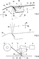
- Figure 4 schematically illustrates an example of a cross-section of the roof panel 34, side panel 35, and laser brazing joint 36 along section A-A shown in figure 3 .
- the underlying body reinforcing structure of the vehicle is not showed in figure 4 .
- the geometry and configuration of the roof panel 34 and side panel 35 in the region of the joint 36 can vary but some kind of flange joint may be preferred.
- a downwardly folded flange 41 of the roof panel 34 abuts and contacts a downwardly folded flange 42 of the side panel 36.
- This design provides a small cavity between the roof panel 34 and side panel 35 at the joint 36, which cavity may be filled with a laser brazing seam formed of molten filler material of the consumable wire 9.
- the roof panel fold 43 between the substantially flat portion of the roof panel facing upwards and the downwardly facing flange 41 of the roof panel 34 may have a radius of not more than 3 mm, specifically not more than 2 mm, and more specifically in the range of 1-2 mm.
- This parameter is relevant from a laser brazing process perspective because it influences the amount of molten filler material that is required to fill the joint 36.
- a radius of more than 3 mm may result in too large fill level, such that the finished laser brazing joint is not sufficiently flush with the outer surface 44 of the roof panel 34.
- a radius of the roof panel fold 43 of less than 1 mm may result in a too small cavity, such that the strength of the laser brazing joint is low.
- Parameter 45 denotes the angle of the downwardly folded flange 42 of the side panel 35 with respect to a vertical direction 99 and parameter 46 denotes the angle between the downwardly folded flange 42 of the side panel 35 and the downwardly folded flange 41 of the roof panel 34.
- Parameter 45 may for example be set to about 30 - 60 degrees, specifically to about 40 - 50 degrees, and more specifically about 45 degrees, because these ranges of said angle enables an high level of tolerance in the lateral distance between side panels on the left and right side of the vehicle, since the roof panel 34 may then automatically fit between side panels 35 on the left and right side of the vehicle at a certain height of the roof.
- a too small angle 45 results in that small variation in lateral distance between the left and right side panels 35 will results in relatively large undesirable vertical position displacement of the roof panel 34.
- a too large angle 45 may result in that the contact point 47 between the roof and side panels 34, 35 will be more difficult to reach for the molten filler material, such that a less strong laser brazing joint is provided.
- the reinforcing capacity of the flanges 41, 42 against bending is reduced with increased angle 45.
- angle 46 should preferably be positive, specifically in the range of 1-10 degrees, because with a negative angle 46 the contact point 47 between the roof and side panels 34, 35 may be located too far down along the flanges 41, 42, and not be reached by molten filler material.
- Parameter 48 may be set to about 2-5 mm because this setting may reduce the risk for complete disintegration of the roof panel to side panel joint in case of a vehicle crash.
- Parameter 49 may be set to at least 1 mm, specifically in the range of 1 - 4 mm, such that the inwardly folded flange 42 of the side panel 35 provides sufficient support to the roof panel 34 in view of the tolerances of the distance between the left and right side panels 35 of the vehicle.
- the parameter 50 may be set to at least 3 mm, specifically in the range of 3 - 10 mm, such that the inwardly folded flange 41 of the roof panel 34 provides sufficient contact surface for supporting the roof panel 34 in view of the tolerances of the distance between the left and right side panels 35 of the vehicle.
- the parameter 51 may be set to at least 1 mm, specifically in the range of 1-10 mm, for proving desired reinforcement of the roof panel against bending, etc.
- the parameter 52 may be set to at least 1 mm, specifically in the range of 1-10, for avoiding undesired contact between the flanges 41, 42.
- Figure 5 schematically illustrates the cross-section of the roof panel 34, side panel 35, and laser brazing joint 36 along section A-A shown in figure 3 , and here also with the laser beam 7 included.
- the laser beam 7 may for example have a direction 62 that is parallel with the vertical direction 99, as seen in the length direction 97 of the vehicle. In other words, the laser beam 7 has zero angle in the lateral direction 98 and does not lean towards the side panel 35 or towards the rood panel 34.
- the laser brazing process has been described primarily for joining the roof panel and side panel of the vehicle, the laser brazing process according to the disclosure may alternatively be used for joining other metal workpieces of a vehicle, such as for example metal parts forming the rear trunk lid.
- FIG. 6 schematically illustrates a 2-D view of the laser brazing process according to the disclosure.
- the laser focus head 5 and consumable wire supply roll 12 is moved in a process direction 11 with a certain process speed, whereby the first and second workpieces 1, 2 are stationary.
- a laser beam process direction angle 61 formed between the direction 62 of the laser beam 7 and an outer surface 63 of the first or second metal workpiece 1, 2, in a plane of the process direction 11, at the beam spot 8, is in the range of 60-90 degrees, specifically in the range of 65-85 degrees, and more specifically in the range of 70-83 degrees.
- This essentially means that the laser focus head 5 has a forward inclination, i.e. a process direction 11 inclination, or that the direction 62 of the laser beam 7 is perpendicular to the surface of the workpieces 1, 2.
- the specific ranges have in experimental testing shown to provide excellent laser brazing finish also with high process speed.
- a longitudinal axis 64 of the consumable wire 9 adjacent the beam spot 8 leans more forward, in a plane of the process direction 11, than the direction 62 of the laser beam 7.
- a feed angle 65 between the direction 62 of the laser beam 7 and the longitudinal axis 64 of the consumable wire 9, in the plane of the process direction 11, adjacent the beam spot 8, may be set in the range of 10-50 degrees, and specifically in the range of 20-40 degrees. The specific ranges have in experimental testing shown to provide excellent laser brazing finish also with high process speed.
- FIG. 7 schematically illustrates an example embodiment of an optical arrangement of the laser source 4 and laser focus head 5.
- the laser source 4 may have one or more laser emitters 70 that generate a laser beam 7 that is guided through a condensing lens 72 before being guided into the entrance of the fibre optic cable 6.
- the fibre optic cable 6 is used for guiding the laser beam from the laser source 4 to the laser focus head 5. This allows significant relative motion between the laser source 4 and laser focus head 5 for improved flexibility.
- a central core 74 of the fibre optic cable 6 may have a diameter 75 of not more than 1 mm, specifically not more than 0.6 mm, and more specifically in the range of 0.2 - 0.6 mm.
- Figure 8 schematically illustrates the intensity profile of Gaussian laser beam, where the X-axis represent location within the laser beam and the Y-axis represents laser beam intensity. As shown, the intensity 85 is largest at the centre 0 of the beam and the intensity smoothly decays from its maximum at the centre to zero intensity at the circumferential edges of the beam 7.
- the total thickness of the beam in this example is about 600 ⁇ m.
- the focus head 5 has a collimating lens arrangement 77 with a first focal length 78 corresponding to the distance between the exit point, i.e. focal point, of the laser beam 7 exiting the fibre optic cable 6 and the collimating lens arrangement 77.
- the focus head 5 further has a focus lens arrangement 79 with a second focal length 80 defined by the distance between the focus lens arrangement 79 and the waist 76, i.e. focal point of the of the laser beam 7 exiting the laser focus head 7.
- each of the collimating lens arrangement 77 and the focus lens arrangement 79 may alternative consists of a plurality of lenses, which combined provides a certain focal length.
- the laser beam exiting the fibre optic cable 6 is guided through the collimating lens arrangement 77 and subsequently through the focus lens arrangement 79 to form the laser beam 7 exiting the laser focus head 5.
- the laser beam 7 exiting the laser focus head 5 is directed towards the elongated contact region of the first and second workpieces 1, 22, and a beam spot 8 formed where the laser beam hits the contact region has a beam spot size 81 in the range of 2 - 6 mm, specifically in the range of 3-5 mm.
- the waist dimension 76 of the laser beam 7, which for example may be about 0.2 - 0.6 mm with an optical magnification near 1:1, may be much smaller than the desired beam spot size of 3-5 mm
- the first and second workpiece 1, 2 may have to be located at a smaller distance 82 from the focusing lend arrangement 79 than the second focal length 80.
- the specific process parameters underlying the laser brazing process according to the disclosure have been identified by conducting extensive research and experimental laser brazing testing, wherein the aim specifically was to identify process parameters that would enables laser brazing of hot-dip galvanised steel with high process speed and high brazing joint finish.
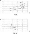
- FIG. 9-12 Specific examples of the result of the experimental results are shown in figures 9-12 .
- All figures 9-12 show experimental results of an identified process window representing acceptable laser brazing results in terms of brazing seam quality, e.g. little amount of spatter, little amount of pores formation and little or no need for refinishing work.
- the charts shown in figures 9-12 illustrate specific examples of the upper and lower limit of the acceptable process window in a process for joining two metal workpieces made of hot-dip galvanised steel by laser brazing for forming a vehicle structure, wherein the X-axis of the chart represents process speed in metres/minute and the Y-axis in the chart represents laser power in kW. No shield gas has been used in any test.
- Figure 9 shows a specific example of an identified acceptable process window for varying process speed and laser power using the following specific test parameter setting:
- Line 91 in figure 9 represents the upper limit of the acceptable process window and line 92 represents the lower limit of the acceptable process window.
- the laser power should be kept between 4 - 5.5 kW for obtaining an acceptable laser brazing result.
- Higher laser power than 5.5 kW may for example result in too much spatter and lower laser power than 4 kW may for result in pores formation.
- the specific example process window shown in figure 9 represents a very good process setting for joining two metal hot-dip galvanized workpieces by laser brazing for forming a vehicle structure.
- the process window shows that by means of the above-defined specific process acceptable laser brazing quality in accomplished over a large range of process speed 11, i.e. from 3.5 metres/minute up to 6.5 metres/minute, merely by adapting the laser power in the range from 3 - 7 kW.
- Experimental results show that that some process parameters are more relevant than others for accomplishing acceptable laser brazing quality of hid-dip galvanized steel while having a relatively high process speed.
- the following process parameters have been identified as more relevant: Beam parameter product, optical magnification level, beam spot size and material of the consumable wire.
- Experimental results show that acceptable process window is accomplished also when said relevant process parameters are varied to a certain extent. In particular, acceptable process window is accomplished when having beam parameter product lower than 10 mm ⁇ mrad, an optical magnification in the range of 1:0.5 - 1:1.5, a beam spot size in the range of 2 - 6 mm and a consumable wire comprising at least 95% copper.
- Figure 10 shows a specific example of an identified acceptable process window for varying process speed and laser power using similar specific test parameter setting as described in relation to figure 9 , but using optical magnification in the laser focus head of 1:3 instead, wherein line 91 represents the upper limit of the acceptable process window and line 92 represents the lower limit of the acceptable process window.
- the distance 82 between the first and second workpiece 1, 2 and the focusing lens arrangement 79 than must be adjusted to obtain the desired beam spot size.
- Figure 11 shows a specific example of an identified acceptable process window for varying process speed and laser power using similar specific test parameter setting as described in relation to figure 9 , but using optical magnification in the laser focus head of 1:5 instead, wherein line 91 represents the upper limit of the acceptable process window and line 92 represents the lower limit of the acceptable process window.
- the distance 82 between the first and second workpiece 1, 2 and the focusing lens arrangement 79 than must be adjusted to obtain the desired beam spot size.
- Figure 12 shows a specific example of an identified acceptable process window for varying process speed and laser power using similar specific test parameter setting as described in relation to figure 9 , wherein the optical magnification in the laser focus head was 1:1, but the consumable wire material was different, namely : ISO 24373; Cu 6560 CuSi3Mn1 (diameter 1.6 mm).
- the typical composition (weight %) of this wire is: Silicon (Si) Iron (Fe) Manganese (Mn) Zinc (Zn) Copper (CU) 2.7 - 3.2% ⁇ 0.2% 0.7 -1.3% ⁇ 0.4% Rest
Landscapes
- Engineering & Computer Science (AREA)
- Mechanical Engineering (AREA)
- Physics & Mathematics (AREA)
- Optics & Photonics (AREA)
- Chemical & Material Sciences (AREA)
- Materials Engineering (AREA)
- Plasma & Fusion (AREA)
- Robotics (AREA)
- Laser Beam Processing (AREA)
Claims (14)
- Procédé pour assembler une première pièce métallique (1) et une deuxième pièce métallique (2) par le brasage au laser pour former une structure de véhicule, comprenant les étapes consistant à :fournir la première pièce métallique (1) et la deuxième pièce métallique (2) l'une étant en contact avec l'autre de manière à former une région de contact allongée (3), au moins l'une des première et deuxième pièces métalliques (1, 2) étant constituée de matériau en acier galvanisé à chaud,fournir un faisceau laser (7) ayant un produit de paramètre de faisceau inférieur à 10 mm·mrad à partir d'une source laser (4),guider le faisceau laser (7) à travers une tête de focalisation laser (5) ayant un grossissement optique total dans la plage de 1:0,5 à 1:1,5,diriger le faisceau laser (7) le long de la région de contact allongée (3), un point de faisceau (8) formé à l'endroit où le faisceau laser (7) frappe la région de contact (3) ayant une taille dans la plage de 2 à 6 mm, etfournir un fil consommable (9) de matériau de remplissage au point de faisceau (8) pour faire fondre le fil consommable (9) et braser lesdites première et deuxième pièces métalliques (1, 2) l'une à l'autre, le fil consommable (9) comprenant au moins 95% de cuivre.
- Procédé selon la revendication 1, dans lequel le faisceau laser (7) comporte un produit de paramètre de faisceau non supérieur à 8 mm·mrad, et spécifiquement dans la gamme de 2 à 8 mm·mrad, et / ou dans lequel la tête de focalisation laser (5) comporte un grossissement optique total dans la gamme de 1:0,7 à 1:1,3, et spécifiquement dans la gamme de 1:0,9 à 1:1,1, et / ou dans lequel le point de faisceau (8) présente une taille dans la gamme de 3 à 5 mm, et / ou dans lequel le fil consommable (9) comprend au moins 96% de cuivre, et spécifiquement au moins 96,5% de cuivre.
- Procédé selon l'une quelconque des revendications précédentes, dans lequel l'au moins une des première et deuxième pièces métalliques (1, 2) réalisées en acier galvanisé à chaud présente un revêtement de zinc dans la gamme de 25 à 95 g/m2, spécifiquement dans la gamme de 35 à 75 g/m2, et plus spécifiquement dans la gamme de 40 à 60 g/m2.
- Procédé selon l'une quelconque des revendications précédentes, dans lequel l'au moins une des première et deuxième pièces métalliques (1, 2) réalisées en acier galvanisé à chaud est en tôle d'acier d'une épaisseur dans la gamme de 0,3 à 1,0 mm, spécifiquement dans la gamme de 0,4 à 0,8 mm, et plus spécifiquement dans la gamme de 0,5 à 0,7 mm.
- Procédé selon l'une quelconque des revendications précédentes, dans lequel le fil consommable (9) comprend moins de 3% de silicium, spécifiquement moins de 2,5% de silicium, et plus spécifiquement de 1 à 2,5% de silicium.
- Procédé selon l'une quelconque des revendications précédentes, dans lequel le fil consommable (9) est du type ISO 24373 ; Cu 6511 CuSi2Mn1.
- Procédé selon l'une quelconque des revendications précédentes, dans lequel le faisceau laser (7) au niveau de la sortie de la source laser (4) présente une puissance d'au moins 2,5 kW, spécifiquement d'au moins 3,5 kW, et plus spécifiquement dans la gamme de 3,5 - 10 kW.
- Procédé selon l'une quelconque des revendications précédentes, comprenant le guidage du faisceau laser (7) depuis la source laser (4) vers la tête de focalisation laser (5) à travers un câble à fibre optique (6) ayant un diamètre de noyau central (75) de pas plus de 1 mm, spécifiquement pas plus de 0,6 mm, et plus spécifiquement dans la gamme de 0,2 à 0,6 mm.
- Procédé selon l'une quelconque des revendications précédentes, comprenant la direction du faisceau laser (7) le long de la région de contact (3) avec une vitesse de traitement d'au moins 3,5 m / min, spécifiquement d'au moins 4,5 m / min, et plus spécifiquement dans la gamme de 3,5 à 6,5 m / min.
- Procédé selon l'une quelconque des revendications précédentes, comprenant la fourniture du fil consommable (9) avec un taux d'alimentation en fil de 50 à 100% de la vitesse de traitement, et spécifiquement 70 à 90% de la vitesse de traitement.
- Procédé selon l'une quelconque des revendications précédentes, dans lequel le fil consommable (9) présente un diamètre de fil dans la gamme de 0,8 à 2,4 mm, spécifiquement dans la gamme de 1,0 à 1,8 mm, et plus spécifiquement dans la gamme de 1,2 à 1,6 mm.
- Procédé selon l'une quelconque des revendications précédentes, dans lequel un angle de direction de traitement du faisceau laser (61) entre le faisceau laser (7) et une surface extérieure (63) de la première ou de la deuxième pièce métallique (1, 2), dans un plan de la direction de traitement (11), au niveau du point de faisceau (8), est dans la gamme de 60 à 90 degrés, spécifiquement dans la gamme de 65 à 85 degrés, et plus spécifiquement dans la gamme de 70 à 83 degrés.
- Procédé selon l'une quelconque des revendications précédentes,dans lequel un axe longitudinal (64) du fil consommable (9) adjacent au point de faisceau (8) présente une inclinaison vers l'avant, dans un plan de la direction de traitement (11), supérieure à une direction (62) du faisceau laser (7) au niveau du point du faisceau (8), etdans lequel un angle d'avance (65) entre la direction (62) du faisceau laser (7) et l'axe longitudinal (64) du fil consommable (9), dans le plan de la direction de traitement (11), adjacent au point de faisceau (8), est dans la gamme de 10 à 50 degrés, et spécifiquement dans la gamme de 20 à 40 degrés.
- Procédé selon l'une quelconque des revendications précédentes, dans lequel l'une des première et deuxième pièces métalliques (1, 2) est un panneau de toit de véhicule (34), et en ce que l'autre pièce métallique est un panneau latéral de véhicule (35).
Priority Applications (4)
| Application Number | Priority Date | Filing Date | Title |
|---|---|---|---|
| EP18155157.3A EP3520945B1 (fr) | 2018-02-05 | 2018-02-05 | Procédé de brasage laser |
| CN201980010249.1A CN111655415B (zh) | 2018-02-05 | 2019-01-15 | 激光钎焊工艺 |
| PCT/CN2019/071816 WO2019149064A1 (fr) | 2018-02-05 | 2019-01-15 | Procédé de brasage laser |
| US16/937,173 US11986898B2 (en) | 2018-02-05 | 2020-07-23 | Laser brazing process |
Applications Claiming Priority (1)
| Application Number | Priority Date | Filing Date | Title |
|---|---|---|---|
| EP18155157.3A EP3520945B1 (fr) | 2018-02-05 | 2018-02-05 | Procédé de brasage laser |
Publications (2)
| Publication Number | Publication Date |
|---|---|
| EP3520945A1 EP3520945A1 (fr) | 2019-08-07 |
| EP3520945B1 true EP3520945B1 (fr) | 2021-01-13 |
Family
ID=61163596
Family Applications (1)
| Application Number | Title | Priority Date | Filing Date |
|---|---|---|---|
| EP18155157.3A Active EP3520945B1 (fr) | 2018-02-05 | 2018-02-05 | Procédé de brasage laser |
Country Status (4)
| Country | Link |
|---|---|
| US (1) | US11986898B2 (fr) |
| EP (1) | EP3520945B1 (fr) |
| CN (1) | CN111655415B (fr) |
| WO (1) | WO2019149064A1 (fr) |
Families Citing this family (4)
| Publication number | Priority date | Publication date | Assignee | Title |
|---|---|---|---|---|
| US20210046568A1 (en) * | 2019-08-13 | 2021-02-18 | Honda Motor Co., Ltd. | Bonding structure of dissimilar metal members and precursor thereof |
| DE102019217912A1 (de) * | 2019-11-20 | 2021-05-20 | Volkswagen Aktiengesellschaft | Verfahren zum Laserstrahllöten |
| CN113351954B (zh) * | 2021-07-06 | 2023-05-26 | 河北华通重工机械制造有限公司 | 一种密封钢圈表面焊接缝钎焊填补装置 |
| CN113579388B (zh) * | 2021-08-24 | 2023-04-28 | 上汽通用汽车有限公司 | 一种车顶激光钎焊热变形模拟方法及车顶激光钎焊方法 |
Family Cites Families (27)
| Publication number | Priority date | Publication date | Assignee | Title |
|---|---|---|---|---|
| JPH0433791A (ja) * | 1990-05-29 | 1992-02-05 | Matsushita Electric Ind Co Ltd | レーザ加工装置 |
| JP3537019B2 (ja) * | 1996-11-22 | 2004-06-14 | 日産自動車株式会社 | 車体パネルのブレージング方法 |
| DE19750586B4 (de) * | 1997-11-17 | 2007-05-16 | Volkswagen Ag | Laser-Lötverfahren |
| JP3901964B2 (ja) * | 2001-08-15 | 2007-04-04 | 日鐵溶接工業株式会社 | 亜鉛メッキ層がある当接部のレーザ溶接方法 |
| JP2003334657A (ja) * | 2002-05-20 | 2003-11-25 | Daihen Corp | 亜鉛メッキ鋼板重ね合わせ継手のアークスポット溶接方法 |
| US6906281B2 (en) * | 2003-03-03 | 2005-06-14 | Dana Corporation | Method for laser welding of metal |
| JP4470482B2 (ja) * | 2003-12-22 | 2010-06-02 | Jfeスチール株式会社 | 重ね隅肉継手のろう付け方法 |
| JP4331012B2 (ja) * | 2004-02-12 | 2009-09-16 | 本田技研工業株式会社 | 硬ろうおよび、この硬ろうを用いたろう接方法 |
| EP1755819A1 (fr) * | 2004-06-04 | 2007-02-28 | Soutec Soudronic AG | Procede de connexion de pieces a assembler par brasage ou soudage et insert destine a la realisation de ce procede |
| JP4506575B2 (ja) * | 2005-06-17 | 2010-07-21 | トヨタ自動車株式会社 | 亜鉛メッキ鋼板レーザろう付け装置、亜鉛メッキ鋼板レーザろう付け方法、ろう付け亜鉛メッキ鋼板製造方法。 |
| JP2007075872A (ja) * | 2005-09-16 | 2007-03-29 | Nissan Motor Co Ltd | レーザブレージング接合工法 |
| KR100711453B1 (ko) * | 2005-12-26 | 2007-04-24 | 주식회사 포스코 | 연속압연을 위한 고탄소강의 용접방법 |
| FR2897007B1 (fr) * | 2006-02-03 | 2008-04-11 | Air Liquide | Procede de coupage avec un laser a fibre avec controle des parametres du faisceau |
| FR2898529B1 (fr) * | 2006-03-15 | 2008-04-25 | Air Liquide | Soudo-brasage de pieces en acier avec fil en cuivre et melange gazeux oxydant |
| EP1920864B1 (fr) * | 2006-11-13 | 2022-07-13 | Volvo Car Corporation | Méthode de brasage par laser à deux points |
| JP2008207246A (ja) * | 2007-01-31 | 2008-09-11 | Jfe Steel Kk | レーザブレージング法 |
| JP5494158B2 (ja) * | 2010-04-12 | 2014-05-14 | 新日鐵住金株式会社 | レーザ・アークろう付け方法 |
| ES2436190T3 (es) * | 2011-07-21 | 2013-12-27 | Ems-Patent Ag | Procedimiento de soldadura láser y piezas formadas con dicho procedimiento |
| DE102012204927B3 (de) * | 2012-03-27 | 2013-07-04 | Thomas Ammersbach | Auftraggeschweißtes Werkstück und Verfahren zur Herstellung eines auftraggeschweißten Werkstückes |
| CN102935560B (zh) * | 2012-11-14 | 2015-01-14 | 四川大西洋焊接材料股份有限公司 | 一种硅青铜焊丝及其制备方法 |
| JP5983345B2 (ja) * | 2012-11-20 | 2016-08-31 | トヨタ自動車株式会社 | 車両用ルーフのレーザロウ付け方法 |
| JP5929948B2 (ja) * | 2014-02-28 | 2016-06-08 | トヨタ自動車株式会社 | 溶接部の検査方法 |
| MX2017004265A (es) * | 2014-10-03 | 2018-01-25 | Honda Motor Co Ltd | Estructura del techo de un vehículo y método para la fabricación de la estructura del techo de un vehículo. |
| JP5955370B2 (ja) * | 2014-10-29 | 2016-07-20 | 株式会社神戸製鋼所 | 金属接合体の製造方法 |
| WO2018025005A1 (fr) * | 2016-08-04 | 2018-02-08 | Spi Lasers Uk Limited | Appareil et procédé de traitement par laser d'un matériau |
| JP6774303B2 (ja) * | 2016-11-02 | 2020-10-21 | 株式会社Subaru | レーザろう付け装置、及びレーザろう付け装置を用いたろう付けワイヤの切断方法 |
| US20190061053A1 (en) * | 2017-08-24 | 2019-02-28 | GM Global Technology Operations LLC | Laser brazing of metal workpieces with relative movement between laser beam and filler wire |
-
2018
- 2018-02-05 EP EP18155157.3A patent/EP3520945B1/fr active Active
-
2019
- 2019-01-15 WO PCT/CN2019/071816 patent/WO2019149064A1/fr not_active Ceased
- 2019-01-15 CN CN201980010249.1A patent/CN111655415B/zh active Active
-
2020
- 2020-07-23 US US16/937,173 patent/US11986898B2/en active Active
Non-Patent Citations (1)
| Title |
|---|
| REIMANN WILFRIED ET AL: "Influence of different zinc coatings on laser brazing of galvanized steel", JOURNAL OF MATERIALS PROCESSING TECHNOLOGY, ELSEVIER, NL, vol. 239, 5 August 2016 (2016-08-05), pages 75 - 82, XP029738787, ISSN: 0924-0136, DOI: 10.1016/J.JMATPROTEC.2016.08.004 * |
Also Published As
| Publication number | Publication date |
|---|---|
| EP3520945A1 (fr) | 2019-08-07 |
| CN111655415B (zh) | 2022-07-15 |
| WO2019149064A1 (fr) | 2019-08-08 |
| CN111655415A (zh) | 2020-09-11 |
| US20200353550A1 (en) | 2020-11-12 |
| US11986898B2 (en) | 2024-05-21 |
Similar Documents
| Publication | Publication Date | Title |
|---|---|---|
| US11986898B2 (en) | Laser brazing process | |
| US20190061053A1 (en) | Laser brazing of metal workpieces with relative movement between laser beam and filler wire | |
| EP3459675B1 (fr) | Procédé de découpe et d'usinage au laser pour tôle en acier plaqué, produit découpé et usiné au laser, tête d'usinage au laser | |
| CN112368105B (zh) | 利用填充丝对涂覆的钢坯件进行激光焊接 | |
| JP7081055B2 (ja) | 1枚またはそれより多いプレス硬化性鋼の薄鋼板の融接のための方法 | |
| JP5110642B2 (ja) | 溶接形鋼の製造方法 | |
| EP3184231B1 (fr) | Procédé de soudage au laser de matériau ayant différentes épaisseurs | |
| DE102015117454A1 (de) | Laser-wärmeleitungsschweissen von aluminiumlegierungen mit doppel-kreuzlaserstrahlen | |
| US20200189035A1 (en) | Method and Device for Fusion Welding One or a Plurality of Steel Sheets Made of Press-Hardenable Steel | |
| WO2019171150A1 (fr) | Procédé de production d'une ébauche métallique soudée et ébauche métallique soudée ainsi obtenue | |
| US10478919B2 (en) | Method for producing aluminum joined body | |
| EP4282571B1 (fr) | Procédé d'assemblage par brasage au laser | |
| JP2010201434A (ja) | レーザブレージング方法 | |
| DE102016014970B4 (de) | Verfahren zum Laserstrahllöten von mindestens zwei schmelztauchbeschichteten Bauteilen oder Blechen miteinander | |
| WO2025126111A1 (fr) | Ensembles soudés au laser | |
| RU2684735C1 (ru) | Способ гибридной лазерно-дуговой сварки стальных труб с наружным плакирующим слоем | |
| EP4247582B1 (fr) | Procédé d'assemblage de pièces en acier | |
| Kimura et al. | Laser brazing phenomena of galvanized steel and pit formation mechanism | |
| CN118679024A (zh) | 激光束焊接方法及其焊接机以及对焊接头 | |
| WO2022185989A1 (fr) | Procédé d'assemblage par brasage au laser | |
| JPH07266068A (ja) | アルミニウム又はアルミニウム合金部材のレーザ溶接方法 | |
| JP7160090B2 (ja) | 金属材料の複合溶接方法および金属材料の突合せ溶接部材 | |
| Park | Laser joining of aluminium to hot-dip galvannealed steel for the use of car bodies | |
| TW202033301A (zh) | 板材的對接雷射焊接法及雷射焊接部件 |
Legal Events
| Date | Code | Title | Description |
|---|---|---|---|
| PUAI | Public reference made under article 153(3) epc to a published international application that has entered the european phase |
Free format text: ORIGINAL CODE: 0009012 |
|
| STAA | Information on the status of an ep patent application or granted ep patent |
Free format text: STATUS: REQUEST FOR EXAMINATION WAS MADE |
|
| 17P | Request for examination filed |
Effective date: 20180205 |
|
| AK | Designated contracting states |
Kind code of ref document: A1 Designated state(s): AL AT BE BG CH CY CZ DE DK EE ES FI FR GB GR HR HU IE IS IT LI LT LU LV MC MK MT NL NO PL PT RO RS SE SI SK SM TR |
|
| AX | Request for extension of the european patent |
Extension state: BA ME |
|
| GRAP | Despatch of communication of intention to grant a patent |
Free format text: ORIGINAL CODE: EPIDOSNIGR1 |
|
| STAA | Information on the status of an ep patent application or granted ep patent |
Free format text: STATUS: GRANT OF PATENT IS INTENDED |
|
| INTG | Intention to grant announced |
Effective date: 20201008 |
|
| GRAS | Grant fee paid |
Free format text: ORIGINAL CODE: EPIDOSNIGR3 |
|
| GRAA | (expected) grant |
Free format text: ORIGINAL CODE: 0009210 |
|
| STAA | Information on the status of an ep patent application or granted ep patent |
Free format text: STATUS: THE PATENT HAS BEEN GRANTED |
|
| AK | Designated contracting states |
Kind code of ref document: B1 Designated state(s): AL AT BE BG CH CY CZ DE DK EE ES FI FR GB GR HR HU IE IS IT LI LT LU LV MC MK MT NL NO PL PT RO RS SE SI SK SM TR |
|
| REG | Reference to a national code |
Ref country code: GB Ref legal event code: FG4D |
|
| REG | Reference to a national code |
Ref country code: CH Ref legal event code: EP |
|
| REG | Reference to a national code |
Ref country code: IE Ref legal event code: FG4D |
|
| REG | Reference to a national code |
Ref country code: DE Ref legal event code: R096 Ref document number: 602018011712 Country of ref document: DE |
|
| REG | Reference to a national code |
Ref country code: AT Ref legal event code: REF Ref document number: 1354186 Country of ref document: AT Kind code of ref document: T Effective date: 20210215 |
|
| REG | Reference to a national code |
Ref country code: AT Ref legal event code: MK05 Ref document number: 1354186 Country of ref document: AT Kind code of ref document: T Effective date: 20210113 |
|
| REG | Reference to a national code |
Ref country code: NL Ref legal event code: MP Effective date: 20210113 |
|
| REG | Reference to a national code |
Ref country code: LT Ref legal event code: MG9D |
|
| PG25 | Lapsed in a contracting state [announced via postgrant information from national office to epo] |
Ref country code: FI Free format text: LAPSE BECAUSE OF FAILURE TO SUBMIT A TRANSLATION OF THE DESCRIPTION OR TO PAY THE FEE WITHIN THE PRESCRIBED TIME-LIMIT Effective date: 20210113 Ref country code: HR Free format text: LAPSE BECAUSE OF FAILURE TO SUBMIT A TRANSLATION OF THE DESCRIPTION OR TO PAY THE FEE WITHIN THE PRESCRIBED TIME-LIMIT Effective date: 20210113 Ref country code: PT Free format text: LAPSE BECAUSE OF FAILURE TO SUBMIT A TRANSLATION OF THE DESCRIPTION OR TO PAY THE FEE WITHIN THE PRESCRIBED TIME-LIMIT Effective date: 20210513 Ref country code: NO Free format text: LAPSE BECAUSE OF FAILURE TO SUBMIT A TRANSLATION OF THE DESCRIPTION OR TO PAY THE FEE WITHIN THE PRESCRIBED TIME-LIMIT Effective date: 20210413 Ref country code: BG Free format text: LAPSE BECAUSE OF FAILURE TO SUBMIT A TRANSLATION OF THE DESCRIPTION OR TO PAY THE FEE WITHIN THE PRESCRIBED TIME-LIMIT Effective date: 20210413 Ref country code: LT Free format text: LAPSE BECAUSE OF FAILURE TO SUBMIT A TRANSLATION OF THE DESCRIPTION OR TO PAY THE FEE WITHIN THE PRESCRIBED TIME-LIMIT Effective date: 20210113 |
|
| PG25 | Lapsed in a contracting state [announced via postgrant information from national office to epo] |
Ref country code: SE Free format text: LAPSE BECAUSE OF FAILURE TO SUBMIT A TRANSLATION OF THE DESCRIPTION OR TO PAY THE FEE WITHIN THE PRESCRIBED TIME-LIMIT Effective date: 20210113 Ref country code: AT Free format text: LAPSE BECAUSE OF FAILURE TO SUBMIT A TRANSLATION OF THE DESCRIPTION OR TO PAY THE FEE WITHIN THE PRESCRIBED TIME-LIMIT Effective date: 20210113 Ref country code: RS Free format text: LAPSE BECAUSE OF FAILURE TO SUBMIT A TRANSLATION OF THE DESCRIPTION OR TO PAY THE FEE WITHIN THE PRESCRIBED TIME-LIMIT Effective date: 20210113 Ref country code: PL Free format text: LAPSE BECAUSE OF FAILURE TO SUBMIT A TRANSLATION OF THE DESCRIPTION OR TO PAY THE FEE WITHIN THE PRESCRIBED TIME-LIMIT Effective date: 20210113 Ref country code: LV Free format text: LAPSE BECAUSE OF FAILURE TO SUBMIT A TRANSLATION OF THE DESCRIPTION OR TO PAY THE FEE WITHIN THE PRESCRIBED TIME-LIMIT Effective date: 20210113 |
|
| PG25 | Lapsed in a contracting state [announced via postgrant information from national office to epo] |
Ref country code: IS Free format text: LAPSE BECAUSE OF FAILURE TO SUBMIT A TRANSLATION OF THE DESCRIPTION OR TO PAY THE FEE WITHIN THE PRESCRIBED TIME-LIMIT Effective date: 20210513 |
|
| REG | Reference to a national code |
Ref country code: DE Ref legal event code: R097 Ref document number: 602018011712 Country of ref document: DE |
|
| REG | Reference to a national code |
Ref country code: BE Ref legal event code: MM Effective date: 20210228 |
|
| PG25 | Lapsed in a contracting state [announced via postgrant information from national office to epo] |
Ref country code: EE Free format text: LAPSE BECAUSE OF FAILURE TO SUBMIT A TRANSLATION OF THE DESCRIPTION OR TO PAY THE FEE WITHIN THE PRESCRIBED TIME-LIMIT Effective date: 20210113 Ref country code: CZ Free format text: LAPSE BECAUSE OF FAILURE TO SUBMIT A TRANSLATION OF THE DESCRIPTION OR TO PAY THE FEE WITHIN THE PRESCRIBED TIME-LIMIT Effective date: 20210113 Ref country code: LI Free format text: LAPSE BECAUSE OF NON-PAYMENT OF DUE FEES Effective date: 20210228 Ref country code: MC Free format text: LAPSE BECAUSE OF FAILURE TO SUBMIT A TRANSLATION OF THE DESCRIPTION OR TO PAY THE FEE WITHIN THE PRESCRIBED TIME-LIMIT Effective date: 20210113 Ref country code: LU Free format text: LAPSE BECAUSE OF NON-PAYMENT OF DUE FEES Effective date: 20210205 Ref country code: SM Free format text: LAPSE BECAUSE OF FAILURE TO SUBMIT A TRANSLATION OF THE DESCRIPTION OR TO PAY THE FEE WITHIN THE PRESCRIBED TIME-LIMIT Effective date: 20210113 Ref country code: CH Free format text: LAPSE BECAUSE OF NON-PAYMENT OF DUE FEES Effective date: 20210228 |
|
| PLBE | No opposition filed within time limit |
Free format text: ORIGINAL CODE: 0009261 |
|
| STAA | Information on the status of an ep patent application or granted ep patent |
Free format text: STATUS: NO OPPOSITION FILED WITHIN TIME LIMIT |
|
| PG25 | Lapsed in a contracting state [announced via postgrant information from national office to epo] |
Ref country code: DK Free format text: LAPSE BECAUSE OF FAILURE TO SUBMIT A TRANSLATION OF THE DESCRIPTION OR TO PAY THE FEE WITHIN THE PRESCRIBED TIME-LIMIT Effective date: 20210113 Ref country code: SK Free format text: LAPSE BECAUSE OF FAILURE TO SUBMIT A TRANSLATION OF THE DESCRIPTION OR TO PAY THE FEE WITHIN THE PRESCRIBED TIME-LIMIT Effective date: 20210113 Ref country code: RO Free format text: LAPSE BECAUSE OF FAILURE TO SUBMIT A TRANSLATION OF THE DESCRIPTION OR TO PAY THE FEE WITHIN THE PRESCRIBED TIME-LIMIT Effective date: 20210113 |
|
| 26N | No opposition filed |
Effective date: 20211014 |
|
| PG25 | Lapsed in a contracting state [announced via postgrant information from national office to epo] |
Ref country code: IE Free format text: LAPSE BECAUSE OF NON-PAYMENT OF DUE FEES Effective date: 20210205 Ref country code: ES Free format text: LAPSE BECAUSE OF FAILURE TO SUBMIT A TRANSLATION OF THE DESCRIPTION OR TO PAY THE FEE WITHIN THE PRESCRIBED TIME-LIMIT Effective date: 20210113 Ref country code: AL Free format text: LAPSE BECAUSE OF FAILURE TO SUBMIT A TRANSLATION OF THE DESCRIPTION OR TO PAY THE FEE WITHIN THE PRESCRIBED TIME-LIMIT Effective date: 20210113 |
|
| PG25 | Lapsed in a contracting state [announced via postgrant information from national office to epo] |
Ref country code: SI Free format text: LAPSE BECAUSE OF FAILURE TO SUBMIT A TRANSLATION OF THE DESCRIPTION OR TO PAY THE FEE WITHIN THE PRESCRIBED TIME-LIMIT Effective date: 20210113 |
|
| PG25 | Lapsed in a contracting state [announced via postgrant information from national office to epo] |
Ref country code: IT Free format text: LAPSE BECAUSE OF FAILURE TO SUBMIT A TRANSLATION OF THE DESCRIPTION OR TO PAY THE FEE WITHIN THE PRESCRIBED TIME-LIMIT Effective date: 20210113 |
|
| PG25 | Lapsed in a contracting state [announced via postgrant information from national office to epo] |
Ref country code: IS Free format text: LAPSE BECAUSE OF FAILURE TO SUBMIT A TRANSLATION OF THE DESCRIPTION OR TO PAY THE FEE WITHIN THE PRESCRIBED TIME-LIMIT Effective date: 20210513 |
|
| PG25 | Lapsed in a contracting state [announced via postgrant information from national office to epo] |
Ref country code: BE Free format text: LAPSE BECAUSE OF NON-PAYMENT OF DUE FEES Effective date: 20210228 |
|
| PG25 | Lapsed in a contracting state [announced via postgrant information from national office to epo] |
Ref country code: NL Free format text: LAPSE BECAUSE OF NON-PAYMENT OF DUE FEES Effective date: 20210113 Ref country code: CY Free format text: LAPSE BECAUSE OF FAILURE TO SUBMIT A TRANSLATION OF THE DESCRIPTION OR TO PAY THE FEE WITHIN THE PRESCRIBED TIME-LIMIT Effective date: 20210113 |
|
| PG25 | Lapsed in a contracting state [announced via postgrant information from national office to epo] |
Ref country code: HU Free format text: LAPSE BECAUSE OF FAILURE TO SUBMIT A TRANSLATION OF THE DESCRIPTION OR TO PAY THE FEE WITHIN THE PRESCRIBED TIME-LIMIT; INVALID AB INITIO Effective date: 20180205 Ref country code: GR Free format text: LAPSE BECAUSE OF FAILURE TO SUBMIT A TRANSLATION OF THE DESCRIPTION OR TO PAY THE FEE WITHIN THE PRESCRIBED TIME-LIMIT Effective date: 20210113 |
|
| PG25 | Lapsed in a contracting state [announced via postgrant information from national office to epo] |
Ref country code: MK Free format text: LAPSE BECAUSE OF FAILURE TO SUBMIT A TRANSLATION OF THE DESCRIPTION OR TO PAY THE FEE WITHIN THE PRESCRIBED TIME-LIMIT Effective date: 20210113 |
|
| PG25 | Lapsed in a contracting state [announced via postgrant information from national office to epo] |
Ref country code: MT Free format text: LAPSE BECAUSE OF FAILURE TO SUBMIT A TRANSLATION OF THE DESCRIPTION OR TO PAY THE FEE WITHIN THE PRESCRIBED TIME-LIMIT Effective date: 20210113 |
|
| PG25 | Lapsed in a contracting state [announced via postgrant information from national office to epo] |
Ref country code: TR Free format text: LAPSE BECAUSE OF FAILURE TO SUBMIT A TRANSLATION OF THE DESCRIPTION OR TO PAY THE FEE WITHIN THE PRESCRIBED TIME-LIMIT Effective date: 20210113 |
|
| PGFP | Annual fee paid to national office [announced via postgrant information from national office to epo] |
Ref country code: GB Payment date: 20251201 Year of fee payment: 9 |
|
| PGFP | Annual fee paid to national office [announced via postgrant information from national office to epo] |
Ref country code: FR Payment date: 20251201 Year of fee payment: 9 |
|
| PGFP | Annual fee paid to national office [announced via postgrant information from national office to epo] |
Ref country code: DE Payment date: 20260217 Year of fee payment: 9 |