EP3520952A2 - Herstellungsverfahren von aluminiumbeschichteten stahlblechen, die zum schweissen und anschliessenden härten unter der presse bestimmt sind - Google Patents
Herstellungsverfahren von aluminiumbeschichteten stahlblechen, die zum schweissen und anschliessenden härten unter der presse bestimmt sind Download PDFInfo
- Publication number
- EP3520952A2 EP3520952A2 EP19176023.0A EP19176023A EP3520952A2 EP 3520952 A2 EP3520952 A2 EP 3520952A2 EP 19176023 A EP19176023 A EP 19176023A EP 3520952 A2 EP3520952 A2 EP 3520952A2
- Authority
- EP
- European Patent Office
- Prior art keywords
- aluminum
- sheets
- welding
- une
- ablation
- Prior art date
- Legal status (The legal status is an assumption and is not a legal conclusion. Google has not performed a legal analysis and makes no representation as to the accuracy of the status listed.)
- Granted
Links
Images


Classifications
-
- B—PERFORMING OPERATIONS; TRANSPORTING
- B23—MACHINE TOOLS; METAL-WORKING NOT OTHERWISE PROVIDED FOR
- B23K—SOLDERING OR UNSOLDERING; WELDING; CLADDING OR PLATING BY SOLDERING OR WELDING; CUTTING BY APPLYING HEAT LOCALLY, e.g. FLAME CUTTING; WORKING BY LASER BEAM
- B23K26/00—Working by laser beam, e.g. welding, cutting or boring
- B23K26/60—Preliminary treatment
-
- B—PERFORMING OPERATIONS; TRANSPORTING
- B23—MACHINE TOOLS; METAL-WORKING NOT OTHERWISE PROVIDED FOR
- B23K—SOLDERING OR UNSOLDERING; WELDING; CLADDING OR PLATING BY SOLDERING OR WELDING; CUTTING BY APPLYING HEAT LOCALLY, e.g. FLAME CUTTING; WORKING BY LASER BEAM
- B23K26/00—Working by laser beam, e.g. welding, cutting or boring
- B23K26/36—Removing material
-
- B—PERFORMING OPERATIONS; TRANSPORTING
- B23—MACHINE TOOLS; METAL-WORKING NOT OTHERWISE PROVIDED FOR
- B23K—SOLDERING OR UNSOLDERING; WELDING; CLADDING OR PLATING BY SOLDERING OR WELDING; CUTTING BY APPLYING HEAT LOCALLY, e.g. FLAME CUTTING; WORKING BY LASER BEAM
- B23K26/00—Working by laser beam, e.g. welding, cutting or boring
- B23K26/20—Bonding
- B23K26/21—Bonding by welding
- B23K26/211—Bonding by welding with interposition of special material to facilitate connection of the parts
-
- B—PERFORMING OPERATIONS; TRANSPORTING
- B23—MACHINE TOOLS; METAL-WORKING NOT OTHERWISE PROVIDED FOR
- B23K—SOLDERING OR UNSOLDERING; WELDING; CLADDING OR PLATING BY SOLDERING OR WELDING; CUTTING BY APPLYING HEAT LOCALLY, e.g. FLAME CUTTING; WORKING BY LASER BEAM
- B23K26/00—Working by laser beam, e.g. welding, cutting or boring
- B23K26/20—Bonding
- B23K26/21—Bonding by welding
- B23K26/24—Seam welding
- B23K26/26—Seam welding of rectilinear seams
-
- B—PERFORMING OPERATIONS; TRANSPORTING
- B23—MACHINE TOOLS; METAL-WORKING NOT OTHERWISE PROVIDED FOR
- B23K—SOLDERING OR UNSOLDERING; WELDING; CLADDING OR PLATING BY SOLDERING OR WELDING; CUTTING BY APPLYING HEAT LOCALLY, e.g. FLAME CUTTING; WORKING BY LASER BEAM
- B23K26/00—Working by laser beam, e.g. welding, cutting or boring
- B23K26/20—Bonding
- B23K26/32—Bonding taking account of the properties of the material involved
-
- B—PERFORMING OPERATIONS; TRANSPORTING
- B23—MACHINE TOOLS; METAL-WORKING NOT OTHERWISE PROVIDED FOR
- B23K—SOLDERING OR UNSOLDERING; WELDING; CLADDING OR PLATING BY SOLDERING OR WELDING; CUTTING BY APPLYING HEAT LOCALLY, e.g. FLAME CUTTING; WORKING BY LASER BEAM
- B23K26/00—Working by laser beam, e.g. welding, cutting or boring
- B23K26/20—Bonding
- B23K26/32—Bonding taking account of the properties of the material involved
- B23K26/322—Bonding taking account of the properties of the material involved involving coated metal parts
-
- B—PERFORMING OPERATIONS; TRANSPORTING
- B23—MACHINE TOOLS; METAL-WORKING NOT OTHERWISE PROVIDED FOR
- B23K—SOLDERING OR UNSOLDERING; WELDING; CLADDING OR PLATING BY SOLDERING OR WELDING; CUTTING BY APPLYING HEAT LOCALLY, e.g. FLAME CUTTING; WORKING BY LASER BEAM
- B23K26/00—Working by laser beam, e.g. welding, cutting or boring
- B23K26/346—Working by laser beam, e.g. welding, cutting or boring in combination with welding or cutting covered by groups B23K5/00 - B23K25/00, e.g. in combination with resistance welding
- B23K26/348—Working by laser beam, e.g. welding, cutting or boring in combination with welding or cutting covered by groups B23K5/00 - B23K25/00, e.g. in combination with resistance welding in combination with arc heating, e.g. tungsten inert gas [TIG], metal inert gas [MIG] or plasma welding
-
- B—PERFORMING OPERATIONS; TRANSPORTING
- B23—MACHINE TOOLS; METAL-WORKING NOT OTHERWISE PROVIDED FOR
- B23K—SOLDERING OR UNSOLDERING; WELDING; CLADDING OR PLATING BY SOLDERING OR WELDING; CUTTING BY APPLYING HEAT LOCALLY, e.g. FLAME CUTTING; WORKING BY LASER BEAM
- B23K26/00—Working by laser beam, e.g. welding, cutting or boring
- B23K26/36—Removing material
- B23K26/361—Removing material for deburring or mechanical trimming
-
- B—PERFORMING OPERATIONS; TRANSPORTING
- B23—MACHINE TOOLS; METAL-WORKING NOT OTHERWISE PROVIDED FOR
- B23K—SOLDERING OR UNSOLDERING; WELDING; CLADDING OR PLATING BY SOLDERING OR WELDING; CUTTING BY APPLYING HEAT LOCALLY, e.g. FLAME CUTTING; WORKING BY LASER BEAM
- B23K26/00—Working by laser beam, e.g. welding, cutting or boring
- B23K26/36—Removing material
- B23K26/40—Removing material taking account of the properties of the material involved
-
- B—PERFORMING OPERATIONS; TRANSPORTING
- B23—MACHINE TOOLS; METAL-WORKING NOT OTHERWISE PROVIDED FOR
- B23K—SOLDERING OR UNSOLDERING; WELDING; CLADDING OR PLATING BY SOLDERING OR WELDING; CUTTING BY APPLYING HEAT LOCALLY, e.g. FLAME CUTTING; WORKING BY LASER BEAM
- B23K26/00—Working by laser beam, e.g. welding, cutting or boring
- B23K26/70—Auxiliary operations or equipment
-
- B—PERFORMING OPERATIONS; TRANSPORTING
- B23—MACHINE TOOLS; METAL-WORKING NOT OTHERWISE PROVIDED FOR
- B23K—SOLDERING OR UNSOLDERING; WELDING; CLADDING OR PLATING BY SOLDERING OR WELDING; CUTTING BY APPLYING HEAT LOCALLY, e.g. FLAME CUTTING; WORKING BY LASER BEAM
- B23K28/00—Welding or cutting not covered by groups B23K5/00 - B23K26/00
- B23K28/02—Combined welding or cutting procedures or apparatus
-
- B—PERFORMING OPERATIONS; TRANSPORTING
- B23—MACHINE TOOLS; METAL-WORKING NOT OTHERWISE PROVIDED FOR
- B23K—SOLDERING OR UNSOLDERING; WELDING; CLADDING OR PLATING BY SOLDERING OR WELDING; CUTTING BY APPLYING HEAT LOCALLY, e.g. FLAME CUTTING; WORKING BY LASER BEAM
- B23K9/00—Arc welding or cutting
- B23K9/16—Arc welding or cutting making use of shielding gas
- B23K9/167—Arc welding or cutting making use of shielding gas and of a non-consumable electrode
-
- B—PERFORMING OPERATIONS; TRANSPORTING
- B23—MACHINE TOOLS; METAL-WORKING NOT OTHERWISE PROVIDED FOR
- B23K—SOLDERING OR UNSOLDERING; WELDING; CLADDING OR PLATING BY SOLDERING OR WELDING; CUTTING BY APPLYING HEAT LOCALLY, e.g. FLAME CUTTING; WORKING BY LASER BEAM
- B23K9/00—Arc welding or cutting
- B23K9/16—Arc welding or cutting making use of shielding gas
- B23K9/173—Arc welding or cutting making use of shielding gas and of a consumable electrode
-
- B—PERFORMING OPERATIONS; TRANSPORTING
- B23—MACHINE TOOLS; METAL-WORKING NOT OTHERWISE PROVIDED FOR
- B23K—SOLDERING OR UNSOLDERING; WELDING; CLADDING OR PLATING BY SOLDERING OR WELDING; CUTTING BY APPLYING HEAT LOCALLY, e.g. FLAME CUTTING; WORKING BY LASER BEAM
- B23K2101/00—Articles made by soldering, welding or cutting
- B23K2101/006—Vehicles
-
- B—PERFORMING OPERATIONS; TRANSPORTING
- B23—MACHINE TOOLS; METAL-WORKING NOT OTHERWISE PROVIDED FOR
- B23K—SOLDERING OR UNSOLDERING; WELDING; CLADDING OR PLATING BY SOLDERING OR WELDING; CUTTING BY APPLYING HEAT LOCALLY, e.g. FLAME CUTTING; WORKING BY LASER BEAM
- B23K2101/00—Articles made by soldering, welding or cutting
- B23K2101/18—Sheet panels
-
- B—PERFORMING OPERATIONS; TRANSPORTING
- B23—MACHINE TOOLS; METAL-WORKING NOT OTHERWISE PROVIDED FOR
- B23K—SOLDERING OR UNSOLDERING; WELDING; CLADDING OR PLATING BY SOLDERING OR WELDING; CUTTING BY APPLYING HEAT LOCALLY, e.g. FLAME CUTTING; WORKING BY LASER BEAM
- B23K2101/00—Articles made by soldering, welding or cutting
- B23K2101/34—Coated articles ; Surface treated articles
-
- B—PERFORMING OPERATIONS; TRANSPORTING
- B23—MACHINE TOOLS; METAL-WORKING NOT OTHERWISE PROVIDED FOR
- B23K—SOLDERING OR UNSOLDERING; WELDING; CLADDING OR PLATING BY SOLDERING OR WELDING; CUTTING BY APPLYING HEAT LOCALLY, e.g. FLAME CUTTING; WORKING BY LASER BEAM
- B23K2103/00—Materials to be soldered, welded or cut
- B23K2103/02—Iron or ferrous alloys
- B23K2103/04—Steel or steel alloys
-
- B—PERFORMING OPERATIONS; TRANSPORTING
- B23—MACHINE TOOLS; METAL-WORKING NOT OTHERWISE PROVIDED FOR
- B23K—SOLDERING OR UNSOLDERING; WELDING; CLADDING OR PLATING BY SOLDERING OR WELDING; CUTTING BY APPLYING HEAT LOCALLY, e.g. FLAME CUTTING; WORKING BY LASER BEAM
- B23K2103/00—Materials to be soldered, welded or cut
- B23K2103/08—Non-ferrous metals or alloys
-
- B—PERFORMING OPERATIONS; TRANSPORTING
- B23—MACHINE TOOLS; METAL-WORKING NOT OTHERWISE PROVIDED FOR
- B23K—SOLDERING OR UNSOLDERING; WELDING; CLADDING OR PLATING BY SOLDERING OR WELDING; CUTTING BY APPLYING HEAT LOCALLY, e.g. FLAME CUTTING; WORKING BY LASER BEAM
- B23K2103/00—Materials to be soldered, welded or cut
- B23K2103/50—Inorganic materials other than metals or composite materials
Definitions
- the invention relates primarily to a process for preparing aluminized steel sheets to be welded.
- the invention also relates to a method for manufacturing welded blanks from the aluminized steel sheets above.
- the invention still primarily relates to a method of manufacturing press hardened parts from blanks welded above, for use as structural parts or safety in motor vehicles.
- welded steel parts from steel blanks of different composition and / or thickness welded together end to end continuously.
- these welded blanks are shaped cold, for example by cold stamping.
- these welded blanks are heated to a temperature allowing austenitization of the steel and then hot deformed and cooled rapidly within the forming tool.
- the present invention relates to this second method of manufacture.
- composition of the steel is chosen to enable the heating and hot deformation steps to be carried out, and to give the final welded part high mechanical strength, high impact resistance and good resistance to corrosion.
- Such steel parts find particular applications in the automotive industry and more particularly for the manufacture of anti-intrusion parts, structural parts or parts involved in the safety of motor vehicles with their shock absorption capacity. .
- the coated steel sheet that is the subject of the publication EP971044 comprises in particular a pre-coating of aluminum alloy or aluminum-based.
- the sheet is coated, for example by dipping continuously, in a bath comprising, besides aluminum, silicon and iron with controlled contents. After hot shaping and cooling, it is possible to obtain a predominantly martensitic microstructure, the tensile strength being able to exceed 1500 MPa.
- a known manufacturing process for welded steel parts consists in supplying at least two steel sheets according to the publication EP971044 , to weld end to end these two sheets to obtain a welded blank, possibly to make a cut of the welded blank, and then to heat the welded blank before carrying out a hot deformation, for example by hot stamping, so as to give the piece of steel the form required for its application.
- a known welding technique is laser beam welding. This technique offers advantages in terms of flexibility, quality and productivity compared to other welding techniques such as knurling or arc welding.
- the aluminum-based pre-coating consisting of an intermetallic alloy layer in contact with the steel substrate, surmounted by a layer of metal alloy, is diluted during the welding operation with the steel substrate within the molten zone which is the zone brought to the liquid state during the welding operation and which solidifies after this welding operation by forming the connection between the two sheets.
- the publication EP2007545 discloses a method of removing at the periphery of the sheets for undergoing the welding operation, the surface metal alloy layer leaving the layer of intermetallic alloy.
- This removal can be achieved by brushing, mechanical machining or by the impact of a laser beam.
- the width of the removal zone is defined by the longitudinal displacement a laser beam of a certain width, or even oscillation of a laser beam smaller than this width, taking as the reference point the edge of the sheet.
- the intermetallic alloy layer is maintained to ensure satisfactory corrosion resistance and to avoid the decarburization and oxidation phenomena during heat treatment that precede the shaping operation.
- the publication WO2013014512 describes a method which consists, in addition to the removal of the metal layer described above, to remove the aluminum present on the edge of the sheets before welding, the presence of which may result from a cutting operation, and to make a joint welded with a material filler wire so as to increase the carbon content of the melted zone, in specific proportions.
- the underlying material has a duller and darker appearance.
- laser welding requires a very precise positioning of the beam with respect to the joint plane formed by the sheets to be assembled.
- This positioning and guidance of the beam or "joint tracking”, is usually carried out by means of sensors capable of detecting the variation, in a direction transverse to the welded joint, of a reflected light beam, the plane of the joint appearing substantially more dark.
- the establishment side-by-side before welding of two sheets including the peripheral ablation of the metal layer has been performed, leads only to a small contrast variation at the docking plane so that it is difficult to detect it and that the guidance of the laser beam is then achieved with less precision.
- An economical preparation method is sought which would eliminate the expensive and delicate operation of cleaning the aluminum or aluminum alloy that has flowed on the secondary side following ablation by melting and vaporization.
- the simultaneous removal by melting and vaporization is performed by a laser beam overlapping said median plane 51.
- the width of the peripheral zone 61 and the width of the peripheral zone 62 are preferably between 0.25 and 2.5 mm.
- the width of the peripheral zone 61 and the width of the peripheral zone 62 are equal.
- the width of the peripheral zone 61 and the width of the peripheral zone 62 are different.
- the removal by melting and vaporization occurs simultaneously on the main faces 111, 121 and 112, 122.
- peripheral zones 61, 62 of each of the first 11 and second steel sheets 12, are devoid of their respective metal alloy layer 19, 20 leaving in place their respective layer of intermetallic alloy 17, 18.
- the substrates 25, 26 have different steel compositions.
- the pre-coatings 15, 16 have different thicknesses
- the metal alloy layer 19, 20 of the pre-coating 15, 16 comprises, the contents being expressed by weight, between 8 and 11% of silicon, between 2 and 4% of iron, the remainder of the composition being aluminum and unavoidable impurities.
- the clearance 31 between the secondary faces 71 and 72 is advantageously greater than 0.04 mm, and very advantageously greater than 0.06 mm.
- the subject of the invention is also a process for manufacturing a welded blank, characterized in that at least a first 11 and a second 12 sheets prepared by a method according to any one of claims 1 to 10 are supplied with, and in that a welding operation of the first sheet 11 and second sheet 12 takes place in the zone of the melt and vaporization removal, according to a plane defined by said median plane 51, less than a minute after the operation removal by melting and vaporization on the first sheet 11 and second sheet 12.
- the welding operation is performed by at least one Laser beam 95.
- the welding operation is performed simultaneously by two laser beams, one welding on the side of the main faces 111 and 121, the other welding on the side of the opposite major faces 112 and 122.
- the fusion and vaporization removal is advantageously carried out by means of a laser beam 80, and the devices making it possible to carry out the removal and the welding operation are combined within an equipment whose relative speed of displacement relative to the first sheet 11 and the second sheet 12, is identical
- the welding operation is performed using simultaneously at least one laser beam 95 and a filler wire 82.
- the removal step is guided by means of a device for tracking the median plane 51, the coordinates (xy) defining the location of the plane 51 at a time t, are recorded by a computer means, and are used to guide the subsequent welding operation.
- the removal step is guided by means of a first device for monitoring the median plane 51, and the welding guide is carried out by means of a second device for monitoring the plane. median, distinct from the first device.
- the plates 11 and 12 are clamped by a clamping device 98 during the melt and vaporization removal operation, the clamping being maintained constantly until the welding operation and at least during the welding operation, by the device 98.
- the hot forming of the welded blank is performed by a hot stamping operation.
- the invention also relates to a welded blank made by assembling at least a first 11 and a second 12 pre-coated steel sheet, consisting of a steel substrate 25,26, and a pre-coated 15,16 coating consisting of a layer of intermetallic alloy 17,18 in contact with the steel substrate, surmounted by a metal layer of aluminum, or aluminum alloy or aluminum-based 19, 20, the first sheet 11 comprising a main face 111, an opposite main face 112, the second sheet 12 comprising a main face 121 and an opposite main face 122, the metal alloy layer 19 being removed by melting and vaporization in a zone peripheral 61 of the sheet 11, and the metal alloy layer 20 in a peripheral zone 62 of the sheet 12, the welded blank having at least one welded joint 52 defining a median plane 51 perpendicular to the main faces of the first 11 and second sheet 12, and sections transverse 52a, 52b, ...
- the sum of the width of the peripheral zones 61 and 62 preferably varies by less than 10% along the welded joint.
- the metal alloy layer 19,20 of the pre-coating 15,16 comprises, the contents being expressed by weight, between 8 and 11% silicon, between 2 and 4% iron, the rest of the composition being aluminum and unavoidable impurities.
- the distance 64 between the laser beams 80 and 95 is between 0.5 mm and 2 m.
- the distance 64 is less than 600 mm. According to a particular mode, the distance 64 is less than 5mm.
- the laser beam 80 opens out from an ablation head
- the beam 95 opens out from a welding head
- the heads forming a compact element whose focusing device is common for the laser beams. 80 and 95.
- the guiding device 94 also makes it possible to position the laser beam 95 with respect to the median plane 51.
- the device further comprises a filler wire device 82 for producing said welded joint.
- the device further comprises a laser beam for welding on the face opposite to that in which the beam 95 operates.
- the invention also relates to the use of a press-hardened part according to the characteristics above, for the manufacture of structural parts, anti-intrusion or shock absorption, in vehicles including automobiles.
- figure 1 which has a macrographic section of a 1 mm thick steel sheet pre-coated with an aluminum alloy, on which was removed by melting and vaporization by means of a laser beam, the layer of alloy superficial metallic.
- the figure 1 thus presents a steel substrate 1 comprising an aluminum pre-coating 2 25 microns thick. Only one of the two main faces of the sheet is illustrated on the macrography. On the periphery of a main face of the sheet, the metallic aluminum layer was removed by means of a pulsed laser beam leaving the intermetallic layer in place, thus creating an ablation zone 3.
- the inventors have demonstrated that this flow phenomenon along the secondary face could be avoided by the following method: according to the figure 2 supplying at least two pre-coated steel sheets 11 and 12, which may be of the same thickness or thickness, figure 2 illustrating the first alternative.
- the plates 11 and 12 are not necessarily rectangular, the geometry of their contour is related to that of the final parts that it is desired to manufacture, which will be obtained by subsequent shaping.
- sheet metal is understood here in a broad sense as any object obtained by cutting from a strip, a reel or a sheet.
- These sheets consist of a steel substrate 25 and 26, which may in particular be in the form of hot rolled sheet or cold rolled according to the desired thickness.
- the composition of these substrates may be identical or different depending on the desired distribution of mechanical characteristics on the final part.
- These steels are heat treatment steels capable of undergoing martensitic or bainitic quenching after an austenitization treatment.
- the thickness of the sheets is preferably between 0.5 and 4 mm, the thickness range used in particular in the manufacture of structural parts or reinforcement for the automotive industry.
- the plates 11 and 12 respectively comprise main faces 111, 112, and 121, 122. At the surface of each of these faces, there is a pre-coating 15 and 16, the thickness and composition of which may be identical or different. in the sheets 1 and 2. These pre-coatings 15 and 16 are both obtained by dipping in an aluminizing bath.
- the pre-coating 16 consists of a layer of intermetallic alloy in contact with the substrate 26 and a surface metal layer.
- the metal alloy 19, 20 of the pre-coating may contain from 8 to 11% by weight of silicon, from 2 to 4% of iron, the remainder of the composition being aluminum and unavoidable impurities.
- silicon makes it possible in particular to reduce the thickness of the intermetallic layer 17.
- the two sheets 11 and 12 can be arranged so that their main faces 111 and 112 are included within the same plane 41. In this way, a laser beam simultaneously implemented on these two sheets will interact in a identical. But one can also predict that the two sheets 11 and 12 are not located exactly on the same plane, that is to say that the focusing point of a laser beam is not located exactly at the same level with respect to the surface of two sheets with an identical pre-coating. This situation can be encountered for example in the case of thickness difference between the two sheets 11 and 12. Even in this case, the inventors have verified that the results sought, in particular the absence of pre-coating flow along the secondary faces, are obtained when the process is implemented according to the invention.
- the two sheets 11 and 12 are docked so as to face two of their secondary faces 71 and 72. This docking thus defines a median plane 51 between the plates 11 and 12, perpendicular to their main faces, and a clearance 31 between them. sheets.
- the respective metal alloy layers 19 and 29 are then simultaneously removed by a process comprising a melting and a vaporization, in a peripheral portion 61 of the plate 11, and a peripheral portion 62 of the plate 12. of these sheets.
- a process comprising a melting and a vaporization, in a peripheral portion 61 of the plate 11, and a peripheral portion 62 of the plate 12. of these sheets.
- This removal also called ablation, is preferably performed by pulsed laser beam.
- the impact of the high energy density and power beam on the pre-coating causes liquefaction and vaporization of the surface of the pre-coating. Due to the plasma pressure, the liquefied pre-coating is expelled to the periphery of the area where the ablation takes place.
- a succession of short laser pulses with suitable parameters leads to ablation of the metal layer 19 and 20, leaving in place the intermetallic alloy layer 17 and 18.
- the ablation is carried out simultaneously on the plates 11 and 12, that is to say that the melting and vaporization means is applied simultaneously to the peripheral zones 61 and 62 opposite one of the other.
- the ablation when the ablation is performed by a laser beam, it impacts the zones 61 and 62 by overlapping the median plane 51.
- a pulsed laser beam of rectangular shape is used. It is also possible to use a laser beam of smaller size that is oscillated to cover the width to be treated.
- the method can also be implemented using a main beam divided into two sub-rectangular beams each overlapping the median plane 51. These two sub-beams can be arranged symmetrically with respect to the plane 51, or be offset longitudinally relative to each other in the welding direction. These two sub-beams may be of identical or different size.
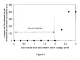
- the inventors have demonstrated that the secondary faces 71 and 72 do not include aluminum flow when the clearance 31 is between 0.02 and 2 mm. Without wishing to be bound by theory, it is believed that the secondary faces 71 and 72 are covered with a very thin layer of iron oxide and / or aluminum coming from the cutting of the plates 11 and 12. interfacial tension between this thin oxide layer and the liquid aluminum on the one hand, and the specific clearance 31 on the other hand, the free surface of the liquid aluminum between the plates 11 and 12 curves to form an angle wetting, without the liquid flowing in the gap 31. A minimum clearance of 0.02 mm allows the beam to pass between the plates 11 and 12, removing any traces of aluminum that could have been on the secondary side.
- the clearance 31 is advantageously greater than 0.04 mm, which makes it possible to implement mechanical cutting processes whose tolerance does not have to be controlled in an extremely strict manner, and makes it possible to reduce the production costs.
- a clearance width 31 greater than 0.06 mm makes it possible to significantly reinforce the optical contrast of the joint plane which appeared in a differentiated from the peripheral ablation zones, and thus to ensure that the welding was well positioned on the median plane 51.
- a clearance of between 0.02 and 0.2mm may be retained.
- a Q-switch type laser of a nominal power of a few hundred watts can be advantageously used, delivering pulses of a duration of the order of about fifty nanoseconds with maximum power. from 1-20 megawatts.
- This type of laser makes it possible, for example, to obtain a rectangular beam impact zone of 2 mm (in the direction of a direction perpendicular to the median plane 51) and of 1 mm, or less than 1 mm, (for example 0.5 mm). in the direction of the length of this median plane.
- the displacement of the beam then makes it possible to create ablation zones 61 and 62 on either side of the plane 51, without any flow occurring along the faces 71 and 72.
- the morphology of the ablation zones 61 and 62 will naturally be adapted to the following welding conditions, in particular to the width of the welded zone: it is thus possible to predict, depending on the nature and the power of the welding process that will follow, that the width of each of the ablation zones 61 and 62 is between 0.25 and 2.5 mm, or for example in the case of laser-arc or plasma hybrid welding, between 0.25 and 3 mm.
- Ablation conditions will be chosen such that the sum of the widths of the ablation zones 61 and 62 is greater than the width of the welded zone.
- the widths of the ablation zones 61 and 62 may also be identical. But it can also be provided, for example by the decentration in the lateral direction, of a laser beam relative to the median plane 51, that the widths of these ablation zones are different.
- ablation can be performed on one side of the main faces.
- the figure 2 thus illustrates this case where simultaneous peripheral ablation was performed only on the side of the main faces 111 and 121.
- this simultaneous peripheral ablation can also be performed preferably on all the faces, ie ie 111, 121, 112, 122.
- a device of the "power switch" type which divides the power of the beam, a part being used for the simultaneous removal of the faces 111 and 121, the other part being used for the simultaneous ablation of the faces 112 and 122.
- a second laser distinct from the first.
- the inventors have also discovered that an online welding operation can be carried out with advantage on the sheets thus prepared. Indeed, given the absence of aluminum flow on the secondary side, the prepared sheets can be welded immediately without the need to remove the sheets of the line and then reposition after cleaning.
- the time interval between the simultaneous ablation operation and the welding operation is less than one minute, so as to minimize oxidation on the faces 71 and 72 and to obtain greater productivity.
- this time interval is small, welding occurs on sheets preheated by the ablation operation, so that the amount of energy to be used for welding is less important.
- a method preferably used is laser welding because of the high energy density inherent in this process, which makes it possible to obtain a narrow melt zone width varying in small proportions.
- This method can be used alone or in combination with a filler wire 82, as shown in FIG. figure 5 . In this case, it is possible to modify the composition of the melted zone by virtue of a composition of the filler wire different from that of the compositions of the plates 25 and 26.
- the welding process associating a laser beam and a filler wire may then consist of either a process where the filler wire is melted only by the laser beam, or a hybrid laser-TIG welding, that is to say a laser beam combined with an electric arc delivered by a welding torch TIG equipped with a non-fuse electrode, or a laser-MIG hybrid welding in which the welding torch is equipped with a fuse wire electrode.
- the devices performing the simultaneous ablation and welding operations are combined in a single device.
- the latter is driven by a single speed of relative movement relative to the sheets.
- the simultaneous ablation speed is identical to the welding speed, which makes it possible to manufacture under optimal conditions of productivity and rationalization.
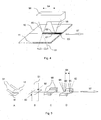
- the figure 4 illustrates a preferred embodiment of the invention: the plates 11 and 12 are shown comprising a pre-coating of aluminum, aluminum alloy or aluminum-based.
- a first laser beam 80 performs a simultaneous ablation of a peripheral zone 61 of the plate 11, and a peripheral zone 62 of the plate 12, the laser beam overlapping the median plane of the plates 11 and 12.
- a second laser beam 81 performs an identical operation simultaneously on the underside of the sheet. According to a variant (not shown in figure 4 ) only a laser beam 80 performs the ablation, it is not performed on the opposite side. This variant will be implemented when it is not necessary to look for a very low aluminum content in the welded zone that will be performed later.
- a laser beam 95 performs the welding of the plates 11 and 12, so as to create a welded zone 63.
- the distance between the ablation and welding devices is kept constant according to a device known in itself schematically represented by 96.
- the plates 11 and 12 move relative to this assembly 96 according to the movement indicated by 97.
- the plates 11 and 12 are advantageously clamped by a clamping device, not shown on the figure 4 .
- the sheets are clamped during the ablation operation of the beams 80 and 81, this clamping is maintained until the included welding, the latter being achieved by the beam 95. In this way, no relative displacement between the plates 11 and 12 does not occur, and the welding through the laser beam 95 can intervene with greater precision.
- the maximum distance between the impact points of the beams 80, 81 on the one hand, and 95 on the other hand depends in particular on the welding speed: as has been seen above, it will be determined in particular so that the time between the impacts of the beams (80, 81) and 95, is less than one minute. This maximum distance may be preferably less than 2 m so that the equipment is particularly compact.
- the minimum distance 64 between these impact points can be reduced to 0.5 mm.
- a distance smaller than 0.5mm would lead to an undesirable interaction between the ablation bundles 80, 81 on the one hand, and the keyhole inherently present during the welding by the beam 95 on the other hand.
- a small distance 64 can also be obtained by combining the two ablation and welding heads (the heads being defined as the devices from which the laser beams open) within a single more compact head, the latter being able to use by example the same focusing element for the ablation and welding operation.
- a very short distance 64 makes it possible to implement the method thanks to a particularly compact equipment and to ensure that a certain quantity of the thermal energy delivered by the laser beams 80 and 81 comes to be added to the linear energy. welding delivered by the beam 95, thereby increasing the overall energy efficiency of the process.
- a very short distance makes it possible to shorten the cycle time necessary for the unitary production of a welded blank, and thus to increase productivity.
- a second laser beam of a type similar to 95, may be applied in the lower part, that is to say on the opposite side. This arrangement makes it possible to increase the welding speed and / or to reduce the unit power of the source 95.
- This beam 95 may be guided by a clean guiding device, distinct from 94 (not shown in FIG. figure 5 ).
- a clean guiding device distinct from 94
- the assembly may comprise a filler wire device 82, so as to change the composition of the melted zone by a composition of the filler wire different from those of the compositions of the plates 25 and 26.
- the sheets 11 and 12 are moved from the station A to the station D, so as to obtain a relative displacement of the sheets relative to the laser beams 80 and 95, these being arranged on the same line with respect to the median plane 51, and at a fixed distance 64 from each other.
- this distance 64 is preferably between 0.5 mm and 2 m, preferably between 0.5 mm and 600 mm, or between 0.5 mm and 5 mm.
- the intermetallic layer is surmounted by a metal layer 25 microns thick, containing by weight 9% silicon, 3% iron, the balance being aluminum and unavoidable impurities.
- These sheets have a dimension of 400 mm x 800 mm.
- the welding is intended to be performed on the long edges of 400mm.
- the guidance of this ablation operation is performed by means of a sensor detecting the position of the median plane between the two sheets, placed immediately upstream with respect to the two pulsed laser ablation beams, at a position denoted x 0 .
- This sensor is located at a distance di of about 100 mm from the ablation beams.
- the coordinates (xo, yo) of the position of the median plane are recorded at a time t 0 by a computer means.
- t 1 t 0 + d 1 V .
- a laser beam located at a fixed distance d 2 of 200mm pulsed laser beams allows for a welded joint between these sheets.
- the welding is carried out with a linear power of 0.6 kJ / cm, under helium protection, so as to avoid phenomena of decarburization, oxidation and absorption of hydrogen.
- the time elapsing between the ablation operation and the welding is 2 seconds.
- the guidance of the laser welding beam is again achieved by the sensor located upstream of the ablation operation.
- the precise position of the impact of the laser welding beam is then adjusted so that it is centered on the position of the median plane which has been defined previously.
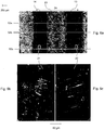
- the figure 6a is a macrography illustrating an elevational view of the laser welded joint obtained, wherein the weld 23 is surrounded by two zones 13 and 14 where the ablation has been performed simultaneously.
- the total ablation width 24 is 1.92 mm on average, and varies less than 10% along the welded blank.
- FIGS. 6b and 6c illustrate at a greater magnification, the surface of zones 21 and 22 arranged symmetrically on either side of section 52a transverse to the welded joint. It can be seen that the solidification ripples of these zones 21 and 22 are identical on both sides of the welded joint and have a character of continuity.
- the aluminum content of the welded zone thus produced was analyzed by Castaing microprobe: it remains less than 0.3%, which indicates that the amount of aluminum on the secondary faces, after the ablation step and before welding, is virtually zero.
- a welded blank made under the conditions of the invention was then heated in an oven to a temperature of 900 ° C and held at that temperature, the total residence time in the oven being 6 minutes.
- the heated blank is then hot-stamped to form a workpiece, which is held in the press press tool so as to cool the workpiece at a speed greater than the critical martensitic quenching speed of the steel.
- the welded zone on the hot-stamped part does not comprise fragile Fe-Al intermetallic compounds, and that the hardness of the melted zone is practically identical to that of the base metal.
- the invention makes it possible to economically produce structural and safety parts for the automotive field, comprising a welded joint, from aluminized sheets.
Landscapes
- Engineering & Computer Science (AREA)
- Physics & Mathematics (AREA)
- Optics & Photonics (AREA)
- Mechanical Engineering (AREA)
- Plasma & Fusion (AREA)
- Laser Beam Processing (AREA)
- Arc Welding In General (AREA)
- Pressure Welding/Diffusion-Bonding (AREA)
- Coating With Molten Metal (AREA)
- Heat Treatment Of Articles (AREA)
- Welding Or Cutting Using Electron Beams (AREA)
- Body Structure For Vehicles (AREA)
- Mounting, Exchange, And Manufacturing Of Dies (AREA)
- Laminated Bodies (AREA)
Priority Applications (1)
| Application Number | Priority Date | Filing Date | Title |
|---|---|---|---|
| PL19176023T PL3520952T3 (pl) | 2014-04-25 | 2015-04-17 | Urządzenie do produkcji spawanych półwyrobów zawierające źródło lasera do zdejmowania przez stapianie i odparowanie warstwy podstawowej aluminium i urządzenie do spawania |
Applications Claiming Priority (4)
| Application Number | Priority Date | Filing Date | Title |
|---|---|---|---|
| PCT/IB2014/000612 WO2015162445A1 (fr) | 2014-04-25 | 2014-04-25 | Procede et dispositif de preparation de toles d'acier aluminiees destinees a etre soudees puis durcies sous presse; flan soude correspondant |
| EP15722763.8A EP3134225B1 (de) | 2014-04-25 | 2015-04-17 | Verfahren und vorrichtung zur herstellung von aluminiumbeschichteten stahlblechen zum schweissen und anschliessenden härten unter druck sowie entsprechender geschweisster rohling |
| PCT/IB2015/000508 WO2015162478A1 (fr) | 2014-04-25 | 2015-04-17 | Procede et dispositif de preparation de toles d'acier aluminiees destinees a etre soudees puis durcies sous presse; flan soude correspondant |
| EP19155807.1A EP3501724B1 (de) | 2014-04-25 | 2015-04-17 | Verfahren zum herstellen einer geschweissten blechplatine, geschweisste blechplatine und werkstück hergestellt von einer solchen geschweissten blechplatine |
Related Parent Applications (3)
| Application Number | Title | Priority Date | Filing Date |
|---|---|---|---|
| EP15722763.8A Division EP3134225B1 (de) | 2014-04-25 | 2015-04-17 | Verfahren und vorrichtung zur herstellung von aluminiumbeschichteten stahlblechen zum schweissen und anschliessenden härten unter druck sowie entsprechender geschweisster rohling |
| EP19155807.1A Division-Into EP3501724B1 (de) | 2014-04-25 | 2015-04-17 | Verfahren zum herstellen einer geschweissten blechplatine, geschweisste blechplatine und werkstück hergestellt von einer solchen geschweissten blechplatine |
| EP19155807.1A Division EP3501724B1 (de) | 2014-04-25 | 2015-04-17 | Verfahren zum herstellen einer geschweissten blechplatine, geschweisste blechplatine und werkstück hergestellt von einer solchen geschweissten blechplatine |
Publications (3)
| Publication Number | Publication Date |
|---|---|
| EP3520952A2 true EP3520952A2 (de) | 2019-08-07 |
| EP3520952A3 EP3520952A3 (de) | 2019-10-09 |
| EP3520952B1 EP3520952B1 (de) | 2021-10-20 |
Family
ID=50685970
Family Applications (4)
| Application Number | Title | Priority Date | Filing Date |
|---|---|---|---|
| EP22157503.8A Pending EP4039403A1 (de) | 2014-04-25 | 2015-04-17 | Verfahren zum herstellen einer geschweissten blechplatine, geschweisste blechplatine, vorrichtung zum herstellen von geschweissten flanschen und werkstück hergetellt von einer solchen geschweissten blechplatine |
| EP19176023.0A Active EP3520952B1 (de) | 2014-04-25 | 2015-04-17 | Vorrichtung zum herstellen von geschweissten flanschen umfassend eine laserquelle zum entfernen durch schmelzen und verdampfen einer aluminium enthaltenden schicht und eine schweisseinrichtung |
| EP15722763.8A Active EP3134225B1 (de) | 2014-04-25 | 2015-04-17 | Verfahren und vorrichtung zur herstellung von aluminiumbeschichteten stahlblechen zum schweissen und anschliessenden härten unter druck sowie entsprechender geschweisster rohling |
| EP19155807.1A Active EP3501724B1 (de) | 2014-04-25 | 2015-04-17 | Verfahren zum herstellen einer geschweissten blechplatine, geschweisste blechplatine und werkstück hergestellt von einer solchen geschweissten blechplatine |
Family Applications Before (1)
| Application Number | Title | Priority Date | Filing Date |
|---|---|---|---|
| EP22157503.8A Pending EP4039403A1 (de) | 2014-04-25 | 2015-04-17 | Verfahren zum herstellen einer geschweissten blechplatine, geschweisste blechplatine, vorrichtung zum herstellen von geschweissten flanschen und werkstück hergetellt von einer solchen geschweissten blechplatine |
Family Applications After (2)
| Application Number | Title | Priority Date | Filing Date |
|---|---|---|---|
| EP15722763.8A Active EP3134225B1 (de) | 2014-04-25 | 2015-04-17 | Verfahren und vorrichtung zur herstellung von aluminiumbeschichteten stahlblechen zum schweissen und anschliessenden härten unter druck sowie entsprechender geschweisster rohling |
| EP19155807.1A Active EP3501724B1 (de) | 2014-04-25 | 2015-04-17 | Verfahren zum herstellen einer geschweissten blechplatine, geschweisste blechplatine und werkstück hergestellt von einer solchen geschweissten blechplatine |
Country Status (18)
| Country | Link |
|---|---|
| US (7) | US10668570B2 (de) |
| EP (4) | EP4039403A1 (de) |
| JP (3) | JP6607868B2 (de) |
| KR (4) | KR102300593B1 (de) |
| CN (1) | CN106232285B (de) |
| AT (3) | AT16149U1 (de) |
| BR (1) | BR112016024413B8 (de) |
| CA (3) | CA3171635A1 (de) |
| DE (1) | DE202015009465U1 (de) |
| ES (3) | ES2726225T3 (de) |
| HU (3) | HUE056437T2 (de) |
| MA (1) | MA39372B1 (de) |
| MX (2) | MX2016014017A (de) |
| PL (3) | PL3134225T3 (de) |
| RU (1) | RU2663664C2 (de) |
| TR (1) | TR201906923T4 (de) |
| UA (1) | UA119457C2 (de) |
| WO (2) | WO2015162445A1 (de) |
Families Citing this family (62)
| Publication number | Priority date | Publication date | Assignee | Title |
|---|---|---|---|---|
| WO2013147035A1 (ja) * | 2012-03-28 | 2013-10-03 | 新日鐵住金株式会社 | ホットスタンプ用テーラードブランクおよびホットスタンプ部材ならびにそれらの製造方法 |
| DE102012111118B3 (de) * | 2012-11-19 | 2014-04-03 | Wisco Tailored Blanks Gmbh | Verfahren zum Laserschweißen eines oder mehrerer Werkstücke aus härtbarem Stahl im Stumpfstoß |
| WO2015162445A1 (fr) * | 2014-04-25 | 2015-10-29 | Arcelormittal Investigación Y Desarrollo Sl | Procede et dispositif de preparation de toles d'acier aluminiees destinees a etre soudees puis durcies sous presse; flan soude correspondant |
| EP3206831B1 (de) * | 2014-10-15 | 2020-05-06 | Autotech Engineering S.L. | Schweissen von stahlblechplatten |
| DE102015115915A1 (de) * | 2015-09-21 | 2017-03-23 | Wisco Tailored Blanks Gmbh | Laserschweißverfahren zur Herstellung eines Blechhalbzeugs aus härtbarem Stahl mit einer Beschichtung auf Aluminium- oder Aluminium-Silizium-Basis |
| KR20180099637A (ko) * | 2015-12-18 | 2018-09-05 | 오토테크 엔지니어링 에이.아이.이. | 강화 구조 컴포넌트들 |
| WO2017109544A1 (fr) * | 2015-12-22 | 2017-06-29 | Arcelormittal | Procede de preparation d'une tole pre-revetue, avec enlevement du revetement a l'aide d'un faisceau laser incline; tôle correspondante |
| CN105689896A (zh) * | 2016-03-23 | 2016-06-22 | 昆山宝锦激光拼焊有限公司 | 一种热轧钢板的涂层去除与焊接一体化的激光加工方法 |
| JP6170643B1 (ja) * | 2016-04-14 | 2017-07-26 | 株式会社アマダホールディングス | レーザ加工機及びレーザ加工方法 |
| JP6238185B2 (ja) | 2016-05-18 | 2017-11-29 | 株式会社アマダホールディングス | めっき鋼板のレーザ切断加工方法、レーザ切断加工品、熱切断加工方法、熱切断加工製品、表面処理鋼板及びレーザ切断方法並びにレーザ加工ヘッド |
| DE102016212057A1 (de) * | 2016-07-01 | 2018-01-04 | Bayerische Motoren Werke Aktiengesellschaft | Verfahren zum Verschweißen von Bauteilen |
| WO2018010132A1 (en) * | 2016-07-14 | 2018-01-18 | GM Global Technology Operations LLC | Multi-beam laser spot welding of coated steels |
| US20180021890A1 (en) * | 2016-07-22 | 2018-01-25 | Caterpillar Inc. | System and method to produce a structure for a weld joint using additive manufacturing |
| WO2018102501A1 (en) * | 2016-12-01 | 2018-06-07 | 3M Innovative Properties Company | Alignment of film in a conversion station |
| JP6959343B2 (ja) * | 2017-01-09 | 2021-11-02 | ヘンケル・アクチェンゲゼルシャフト・ウント・コムパニー・コマンディットゲゼルシャフト・アウフ・アクチェンHenkel AG & Co. KGaA | 硬化性保護コーティング組成物 |
| DE102017111211B4 (de) * | 2017-05-23 | 2023-10-12 | Automotive Lighting Reutlingen Gmbh | Verfahren zur Material abtragenden Laserbearbeitung eines Werkstücks |
| WO2018220430A1 (en) * | 2017-06-02 | 2018-12-06 | Arcelormittal | Steel sheet for manufacturing press hardened parts, press hardened part having a combination of high strength and crash ductility, and manufacturing methods thereof |
| CA3066259C (en) | 2017-06-28 | 2023-05-23 | Arconic Inc. | Preparation methods for adhesive bonding of 7xxx aluminum alloys, and products relating to the same |
| RU2742207C1 (ru) * | 2017-10-20 | 2021-02-03 | Арселормиттал | Способ производства листовой стали с предварительно нанесенным покрытием и соответствующий лист |
| WO2019090109A1 (en) | 2017-11-02 | 2019-05-09 | Ak Steel Properties, Inc. | Press hardened steel with tailored properties |
| BR112020008509A2 (pt) * | 2017-11-08 | 2020-10-20 | Nippon Steel Corporation | chapa de aço, tailored blank, produto estampado a quente, tubo de aço, produto estampado a quente oco, método de fabricação de chapa de aço, método de fabricação de tailored blank, método de fabricação de produto estampado a quente, método de fabricação de tubo de aço e método de fabricação de produto estampado a quente oco |
| CA2986676C (en) * | 2017-11-24 | 2020-01-07 | Bombardier Transportation Gmbh | Method for automated straightening of welded assemblies |
| JP7047387B2 (ja) * | 2018-01-10 | 2022-04-05 | 日本製鉄株式会社 | 鋼板、突合せ溶接部材、熱間プレス成形品、鋼管、中空状焼入れ成形品、および鋼板の製造方法 |
| WO2019166852A1 (en) * | 2018-02-27 | 2019-09-06 | Arcelormittal | Method for producing a press-hardened laser welded steel part and press-hardened laser welded steel part |
| DE102018104829A1 (de) * | 2018-03-02 | 2019-09-05 | Voestalpine Automotive Components Linz Gmbh | Verfahren zur Schweißvorbehandlung beschichteter Stahlbleche |
| WO2019171150A1 (en) | 2018-03-08 | 2019-09-12 | Arcelormittal | Method for producing a welded metal blank and thus obtained welded metal blank |
| CN108202226A (zh) * | 2018-03-13 | 2018-06-26 | 大连理工大学 | 一种铝镁合金板料温热成形生产线及其生产工艺 |
| CN108466011A (zh) * | 2018-03-19 | 2018-08-31 | 上海宝钢阿赛洛激光拼焊有限公司 | 提高钢材焊接性能的预处理方法及焊接冲压方法 |
| DE102018107291B4 (de) * | 2018-03-27 | 2025-11-06 | Voestalpine Automotive Components Linz Gmbh | Verfahren zum Schweißen beschichteter Stahlbleche |
| HUE072679T2 (hu) * | 2018-03-30 | 2025-12-28 | Furukawa Electric Co Ltd | Hegesztési eljárás és hegesztõkészülék |
| CN108568610A (zh) * | 2018-05-17 | 2018-09-25 | 上海宝钢阿赛洛激光拼焊有限公司 | 采用水射流提高钢材焊接性能的方法及其焊接方法 |
| CN108941876A (zh) * | 2018-06-07 | 2018-12-07 | 上海宝钢阿赛洛激光拼焊有限公司 | 去除钢板表面涂层的方法及焊接冲压方法 |
| KR102451642B1 (ko) * | 2018-06-22 | 2022-10-11 | 닛폰세이테츠 가부시키가이샤 | 강판, 테일러드 블랭크, 열간 프레스 성형품, 강관, 중공상 ??칭 성형품, 강판의 제조 방법, 테일러드 블랭크의 제조 방법, 열간 프레스 성형품의 제조 방법, 강관의 제조 방법 및 중공상 ??칭 성형품의 제조 방법 |
| US11203085B2 (en) * | 2018-09-25 | 2021-12-21 | GM Global Technology Operations LLC | Method and apparatus for laser welding |
| CN111360406B (zh) * | 2018-12-07 | 2022-03-08 | 中国科学院上海光学精密机械研究所 | 一种由钢制的基体和预镀层构成的板材的激光焊接方法 |
| US20220072658A1 (en) * | 2018-12-24 | 2022-03-10 | Arcelormittal | Method for producing a welded steel blank and associated welded steel blank |
| JP7307307B2 (ja) * | 2019-02-04 | 2023-07-12 | 日本製鉄株式会社 | 突合せ溶接用アルミニウムめっき鋼板、突合せ溶接部材及び熱間プレス成形品 |
| US11583954B2 (en) * | 2019-03-04 | 2023-02-21 | Kabushiki Kaisha Toshiba | Welding method |
| JP7328835B2 (ja) * | 2019-03-04 | 2023-08-17 | 株式会社東芝 | 溶接方法 |
| EP3941675B1 (de) * | 2019-03-22 | 2025-08-27 | DMC Global Inc. | Plattierter artikel mit plattierungsschicht mit unterschiedlicher dicke und verfahren zur herstellung eines plattierten artikels |
| CN111230301B (zh) * | 2019-03-29 | 2022-08-12 | 宝山钢铁股份有限公司 | 带铝或铝合金镀层的钢制薄壁焊接等强部件的制造方法 |
| JP6601598B1 (ja) * | 2019-04-02 | 2019-11-06 | 日本製鉄株式会社 | 鋼板、テーラードブランク、熱間プレス成形品の製造方法、鋼管、及び中空状焼入れ成形品の製造方法 |
| EP3946795A1 (de) | 2019-04-05 | 2022-02-09 | Cleveland-Cliffs Steel Properties Inc. | Abschirmung und kühlung einer kontinuierlichen schweissnaht zwischen stahlblechen/-platten unter verwendung einer nichtoxidierenden atmosphäre zur verminderung der oxidbildung auf einer oberfläche der kontinuierlichen schweissnaht |
| JP7426576B2 (ja) * | 2019-05-15 | 2024-02-02 | 日本製鉄株式会社 | テーラードブランクおよびテーラードブランク用鋼板の製造方法 |
| CN110587135B (zh) * | 2019-08-14 | 2021-09-24 | 上海宝钢阿赛洛激光拼焊有限公司 | 激光拼焊板焊缝防冲压开裂的焊接方法 |
| DE102019131906A1 (de) | 2019-11-26 | 2021-05-27 | Voestalpine Automotive Components Linz Gmbh | Verfahren zum Verschweißen beschichteter Stahlbleche |
| DE102019131908A1 (de) * | 2019-11-26 | 2021-05-27 | Voestalpine Automotive Components Linz Gmbh | Verfahren zum Verschweißen beschichteter Stahlbleche |
| JP7440637B2 (ja) * | 2019-12-19 | 2024-02-28 | アルセロールミタル | プレコート鋼ブランク及び関連するブランクのレーザ切断 |
| JP7207573B2 (ja) * | 2019-12-20 | 2023-01-18 | 日本電信電話株式会社 | クリーニング方法および装置 |
| WO2021130524A1 (en) * | 2019-12-24 | 2021-07-01 | Arcelormittal | Pre-coated steel sheet comprising an additional coating for increasing the mechanical strength of the weld metal zone of a welded steel part prepared from said pre-coated sheet |
| DE102020117169A1 (de) | 2020-06-30 | 2021-12-30 | Audi Aktiengesellschaft | Schweißvorrichtung |
| WO2022011374A2 (en) * | 2020-07-06 | 2022-01-13 | Novelis Inc. | Metal joiner system, associated methods, and products |
| KR102308832B1 (ko) | 2020-10-29 | 2021-10-05 | 현대제철 주식회사 | 알루미늄계 도금 블랭크 및 이의 제조방법 |
| WO2022096921A1 (en) * | 2020-11-06 | 2022-05-12 | Arcelormittal | Rear underfloor structure for a motor vehicle |
| CN112455024B (zh) * | 2021-02-03 | 2021-04-27 | 育材堂(苏州)材料科技有限公司 | 激光拼焊预镀层钢板及其热冲压成形构件 |
| CN113172341B (zh) * | 2021-06-07 | 2022-11-11 | 中创新航技术研究院(江苏)有限公司 | 电池盖板的焊接方法 |
| WO2023110583A1 (de) * | 2021-12-17 | 2023-06-22 | Trumpf Laser- Und Systemtechnik Gmbh | VERFAHREN ZUM SCHWEIßEN VON ZINKBESCHICHTETEN STAHLBLECHEN MIT EINEM LASERSTRAHL |
| CN115008014A (zh) * | 2022-08-10 | 2022-09-06 | 理世(湖北)实业股份有限公司 | 一种高强度钢的激光焊接系统及激光焊接方法 |
| WO2025192694A1 (ja) * | 2024-03-14 | 2025-09-18 | 日本発條株式会社 | 高張力鋼板のレーザ溶接方法、レーザ溶接接合体および車両用シートフレーム |
| CN118237341B (zh) * | 2024-05-28 | 2024-09-03 | 哈尔滨工业大学(威海) | 一种集成有激光清洗功能的水下激光作业一体化接头 |
| EP4678306A1 (de) * | 2024-07-12 | 2026-01-14 | voestalpine Stahl GmbH | Verfahren und vorrichtung zum verschweissen von stahlbändern |
| CN119282400B (zh) * | 2024-11-21 | 2026-02-13 | 江西豪斯特汽车零部件有限公司 | 一种1500MPa级抗氧化热成形钢的激光拼焊方法 |
Citations (3)
| Publication number | Priority date | Publication date | Assignee | Title |
|---|---|---|---|---|
| EP0971044A1 (de) | 1998-07-09 | 2000-01-12 | Sollac | Beschichtetes warmgewalztes und kaltgewalztes Stahlblech mit sehr hoher Festigkeit nach thermischer Behandlung |
| EP2007545A1 (de) | 2006-04-19 | 2008-12-31 | ArcelorMittal France | Verfahren zur herstellung eines geschweissten teils mit sehr guten mechanischen eigenschaften aus einer beschichteten schutzfolie |
| WO2013014512A1 (fr) | 2011-07-26 | 2013-01-31 | Arcelormittal Investigación Y Desarrollo Sl | Pièce d'acier soudée mise en forme à chaud à très haute résistance mécanique et procédé de fabrication |
Family Cites Families (83)
| Publication number | Priority date | Publication date | Assignee | Title |
|---|---|---|---|---|
| DE3502368A1 (de) | 1985-01-25 | 1986-07-31 | Thyssen Stahl AG, 4100 Duisburg | Verfahren zum stumpfschweissen von mindestens einseitig verzinkten, insbesondere tiefziehfaehigen stahlblechen oder stahlbaender |
| JPS63130295A (ja) * | 1986-11-20 | 1988-06-02 | Mitsubishi Electric Corp | レ−ザ光によるワ−ク熱処理方法 |
| US5215220A (en) | 1991-04-30 | 1993-06-01 | Courtesy Corporation | Tamper evident closure with dispensing spout and integral opening member |
| DE59302322D1 (de) | 1992-04-12 | 1996-05-30 | Elpatronic Ag | Verfahren und Vorrichtung zum Schweissen von Blechen zu Platinen mittels Laser |
| JPH06246575A (ja) | 1993-02-22 | 1994-09-06 | Mitsubishi Heavy Ind Ltd | 供給材基準点と加工機原点の自動合せ装置 |
| DE4328516A1 (de) | 1993-03-02 | 1994-09-08 | Wicona Bausysteme Gmbh | Verfahren und Vorrichtung zum Herstellen einer Stoßverbindung von zwei Profilstäben aus Metall, inbes. aus Aluminium oder einer Aluminiumlegierung |
| JPH06246475A (ja) * | 1993-03-03 | 1994-09-06 | Nippon Steel Corp | レーザ溶接方法 |
| FR2705601B1 (fr) | 1993-05-28 | 1995-08-18 | Lorraine Laminage | Dispositif de guidage et de transfert d'au moins deux flans de tôle préalablement accostés bord à bord et installation de soudage comportant un tel dispositif de guidage et de transfert. |
| US5389761A (en) * | 1993-09-17 | 1995-02-14 | General Motors Corporation | Method and apparatus for cleaning metal pieces prior to resistive seam welding or laser lap seam welding |
| US5622540A (en) * | 1994-09-19 | 1997-04-22 | Corning Incorporated | Method for breaking a glass sheet |
| US5811756A (en) | 1995-01-23 | 1998-09-22 | Nippon Light Metal Company, Inc. | ARC welding method for aluminum members and welded product excellent in dimensional accuracy and external appearance |
| DE19501945A1 (de) | 1995-01-24 | 1996-07-25 | Alcatel Kabel Ag | Verfahren zur Herstellung längsnahtgeschweißter Metallrohre |
| US5603853A (en) | 1995-02-28 | 1997-02-18 | The Twentyfirst Century Corporation | Method of high energy density radiation beam lap welding |
| US5595670A (en) * | 1995-04-17 | 1997-01-21 | The Twentyfirst Century Corporation | Method of high speed high power welding |
| JPH10225770A (ja) | 1997-02-14 | 1998-08-25 | Sangyo Souzou Kenkyusho | 溶接装置 |
| CA2199355A1 (en) | 1997-03-06 | 1998-09-06 | Bob Bishop | Multiple beam laser welding apparatus |
| DE19724986C2 (de) * | 1997-06-13 | 1999-07-29 | Jurca Optoelektronik Gmbh | Verfahren zum Verschweißen von Werkstücken und Vorrichtung zu dessen Durchführung |
| CA2242139A1 (en) | 1998-06-29 | 1999-12-29 | Automated Welding Systems Incorporated | Method of laser welding tailored blanks |
| AU2001250208A1 (en) * | 2000-04-11 | 2001-10-23 | Gsi Lumonics Inc. | A method and system for laser drilling |
| SG108262A1 (en) | 2001-07-06 | 2005-01-28 | Inst Data Storage | Method and apparatus for cutting a multi-layer substrate by dual laser irradiation |
| US6803538B2 (en) * | 2001-08-31 | 2004-10-12 | Honda Canada Inc. | Laser welding system |
| JP2003223213A (ja) * | 2002-01-31 | 2003-08-08 | Nippei Toyama Corp | ティーチング方法及びその装置並びにティーチング装置を備えたレーザ加工機 |
| AU2003211581A1 (en) * | 2002-03-12 | 2003-09-22 | Hamamatsu Photonics K.K. | Method of cutting processed object |
| JP2004001081A (ja) * | 2002-03-27 | 2004-01-08 | Sumikin Plant Ltd | 金属板の突き合わせ溶接方法及び装置 |
| US6987693B2 (en) | 2002-09-24 | 2006-01-17 | Sandisk Corporation | Non-volatile memory and method with reduced neighboring field errors |
| JP4120408B2 (ja) * | 2003-01-21 | 2008-07-16 | Jfeエンジニアリング株式会社 | レーザとアークの複合溶接方法およびそれに用いる溶接継手の開先形状 |
| JP2004249305A (ja) | 2003-02-19 | 2004-09-09 | Enshu Ltd | レーザ溶接方法とそのレーザ溶接システム |
| JP2005169444A (ja) * | 2003-12-10 | 2005-06-30 | Sumitomo Electric Ind Ltd | 絶縁被覆導体の接合方法および絶縁被覆導体の接合装置 |
| US20060261045A1 (en) * | 2005-05-18 | 2006-11-23 | Pei-Chung Wang | Multi-heat source laser brazing system and method |
| WO2007105567A1 (ja) | 2006-03-10 | 2007-09-20 | Toppan Printing Co., Ltd. | カラーフィルタおよびその製造に用いるフォトマスク |
| FR2903623B1 (fr) * | 2006-07-12 | 2008-09-19 | L'air Liquide | Procede de soudage hybride laser-arc de pieces metalliques aluminiees |
| US7732351B2 (en) * | 2006-09-21 | 2010-06-08 | Semiconductor Energy Laboratory Co., Ltd. | Manufacturing method of semiconductor device and laser processing apparatus |
| FR2906171B1 (fr) * | 2006-09-22 | 2009-05-15 | Vai Clecim Sa | Dispositif de raboutage par soudure de bandes de toles |
| BRPI0622071A2 (pt) | 2006-10-30 | 2014-05-27 | Arcelormittal France | Tiras de aço revestidas, métodos de produção da mesma, métodos de uso das mesmas, discos de estampagem preparados a partir das mesmas, e produtos que contenham tal produto estampado |
| US20080128053A1 (en) * | 2006-12-05 | 2008-06-05 | Noble Advanced Technologies | Method of manufacturing a welded metal panel having a high quality surface finish |
| US8026654B2 (en) * | 2007-01-18 | 2011-09-27 | Federal-Mogul World Wide, Inc. | Ignition device having an induction welded and laser weld reinforced firing tip and method of construction |
| US8506480B2 (en) | 2007-07-11 | 2013-08-13 | Sotera Wireless, Inc. | Device for determining respiratory rate and other vital signs |
| DE102007058568B4 (de) | 2007-11-29 | 2010-09-30 | Fraunhofer-Gesellschaft zur Förderung der angewandten Forschung e.V. | Verfahren zum defektfreien Schweißen metallischer Bauteile mit Elektronen- oder Laserstrahl |
| DE102008006241A1 (de) | 2008-01-25 | 2009-07-30 | Thyssenkrupp Steel Ag | Verfahren und Vorrichtung zum Abtragen einer metallischen Beschichtung |
| DE102008006624B4 (de) | 2008-01-29 | 2012-10-18 | Thyssenkrupp Steel Europe Ag | Verfahren zum Fügen beschichteter Stahlsubstrate |
| GB2457720A (en) | 2008-02-23 | 2009-08-26 | Philip Thomas Rumsby | Method for laser processing on the opposite sides of thin transparent substrates |
| US20100078412A1 (en) * | 2008-09-30 | 2010-04-01 | Caterpillar Inc. | Hybrid welding method |
| PT2414131E (pt) * | 2009-03-30 | 2015-09-04 | Boegli Gravures Sa | Método e dispositivo para a estruturação de uma superfície de um corpo sólido com um revestimento duro com o auxílio de um laser utilizando máscara e diafragma |
| US20100288738A1 (en) * | 2009-05-15 | 2010-11-18 | General Electric Company | Welding apparatus and method |
| JP5479024B2 (ja) * | 2009-10-27 | 2014-04-23 | パナソニック株式会社 | 接合方法および接合装置 |
| JP5827454B2 (ja) * | 2010-03-08 | 2015-12-02 | 株式会社神戸製鋼所 | レーザー・アーク複合溶接方法及び該溶接方法による溶接部材の製造方法 |
| WO2011118172A1 (ja) * | 2010-03-24 | 2011-09-29 | パナソニック株式会社 | レーザ溶接方法およびレーザ溶接装置 |
| US8253060B2 (en) * | 2010-06-30 | 2012-08-28 | General Electric Company | Hybrid laser arc welding process and apparatus |
| US8253061B2 (en) * | 2010-07-07 | 2012-08-28 | General Electric Company | Hybrid laser arc welding process and apparatus |
| RU2013102422A (ru) * | 2010-07-12 | 2014-08-20 | ФАЙЛЭЙСЕР ЮЭс-Эй ЭлЭлСи | Способ обработки материалов с использованием филаментации |
| FR2962673B1 (fr) * | 2010-07-13 | 2013-03-08 | Air Liquide | Procede de soudage hybride arc/laser de pieces en acier aluminise avec fil a elements gamagenes |
| US9187318B2 (en) * | 2010-09-21 | 2015-11-17 | Technical Institute of Physics and Chemistry of the Chinese Academy of Sciences | Laser micro/nano processing system and method |
| CA2819095C (en) * | 2010-12-17 | 2018-09-04 | Magna International Inc. | Laser beam welding |
| KR101246909B1 (ko) | 2011-01-11 | 2013-03-25 | 엔케이에스주식회사 | 핫 스탬핑 강판의 접합방법 |
| US8546720B2 (en) * | 2011-04-13 | 2013-10-01 | General Electric Company | Hybrid welding apparatus and system and method of welding |
| DE102011002023A1 (de) | 2011-04-13 | 2012-10-18 | Hugo Miebach Gmbh | Verfahren und Vorrichtung zum Laserstrahlschweißen von Blechen |
| JP5808592B2 (ja) | 2011-07-04 | 2015-11-10 | 浜松ホトニクス株式会社 | 基準電圧決定方法及び推奨動作電圧決定方法 |
| US20130056449A1 (en) * | 2011-09-07 | 2013-03-07 | General Electric Company | Welding system and method |
| US8766140B2 (en) | 2011-10-06 | 2014-07-01 | Lincoln Global, Inc. | Apparatus and method for laser cleaning of coated materials prior to welding |
| US20130087543A1 (en) * | 2011-10-06 | 2013-04-11 | Lincoln Global, Inc. | Apparatus and method for post weld laser release of gas build up in a gmaw weld |
| US20130309000A1 (en) * | 2012-05-21 | 2013-11-21 | General Electric Comapny | Hybrid laser arc welding process and apparatus |
| WO2013177590A1 (en) * | 2012-05-25 | 2013-11-28 | Shiloh Industries, Inc. | Sheet metal piece having weld notch and method of forming the same |
| MX353799B (es) * | 2012-06-29 | 2018-01-30 | Shiloh Ind Inc | Ensamble y método de plantilla soldada. |
| US9221118B2 (en) * | 2012-07-26 | 2015-12-29 | General Electric Company | Adaptive control hybrid welding system and methods of controlling |
| US9278407B2 (en) * | 2012-07-26 | 2016-03-08 | General Electric Company | Dual-wire hybrid welding system and method of welding |
| US20140034622A1 (en) | 2012-08-03 | 2014-02-06 | Lincoln Global, Inc. | Method and system for narrow grove welding using laser and hot-wire system |
| US8941031B2 (en) * | 2012-08-22 | 2015-01-27 | Caterpillar Inc. | Systems and methods for dual-weave welding |
| JP2014050857A (ja) | 2012-09-06 | 2014-03-20 | Uacj Corp | 温間絞り成形装置及び温間絞り成形方法 |
| DE102012111118B3 (de) * | 2012-11-19 | 2014-04-03 | Wisco Tailored Blanks Gmbh | Verfahren zum Laserschweißen eines oder mehrerer Werkstücke aus härtbarem Stahl im Stumpfstoß |
| MX381438B (es) * | 2012-11-30 | 2025-03-04 | Twb Company Llc | Metodo para formar una muesca de soldadura en una pieza de metal en hoja. |
| KR101448473B1 (ko) | 2012-12-03 | 2014-10-10 | 현대하이스코 주식회사 | 테일러 웰디드 블랭크, 그 제조방법 및 이를 이용한 핫스탬핑 부품 |
| KR101416411B1 (ko) * | 2012-12-28 | 2014-08-08 | 현대자동차 주식회사 | 레이저 용접기 |
| EP2969347B1 (de) * | 2013-03-14 | 2019-11-20 | Shiloh Industries, Inc. | Zusammengeschweisste rohlinge |
| KR101346317B1 (ko) | 2013-07-09 | 2013-12-31 | 에스아이에스 주식회사 | 맞춤 재단 용접 판재의 용접을 위해 Al-Si도금층을 제거하기 위한 레이저 삭마 장치 |
| US10537027B2 (en) * | 2013-08-02 | 2020-01-14 | Orbotech Ltd. | Method producing a conductive path on a substrate |
| EP2883646B1 (de) | 2013-12-12 | 2016-11-02 | Autotech Engineering, A.I.E. | Verfahren zum Verbinden von zwei Rohlingen sowie Rohlinge und erhaltenes Produkte |
| JP2015188939A (ja) * | 2014-03-31 | 2015-11-02 | アイシン精機株式会社 | レーザ接合方法、レーザ接合品及びレーザ接合装置 |
| JP6032236B2 (ja) * | 2014-04-08 | 2016-11-24 | トヨタ自動車株式会社 | レーザ溶接方法および溶接構造 |
| WO2015162445A1 (fr) | 2014-04-25 | 2015-10-29 | Arcelormittal Investigación Y Desarrollo Sl | Procede et dispositif de preparation de toles d'acier aluminiees destinees a etre soudees puis durcies sous presse; flan soude correspondant |
| WO2015192219A1 (en) * | 2014-06-19 | 2015-12-23 | Magna International Inc. | Process and system for laser welding pre-coated sheet metal workpieces |
| US9925715B2 (en) * | 2014-06-30 | 2018-03-27 | General Electric Company | Systems and methods for monitoring a melt pool using a dedicated scanning device |
| US10052720B2 (en) | 2014-09-17 | 2018-08-21 | Magna International Inc. | Method of laser welding coated steel sheets with addition of alloying elements |
| US10272524B2 (en) * | 2014-10-22 | 2019-04-30 | GM Global Technology Operations LLC | Laser conduction mode welding of aluminum alloys with cross dual laser beams |
-
2014
- 2014-04-25 WO PCT/IB2014/000612 patent/WO2015162445A1/fr not_active Ceased
-
2015
- 2015-04-17 ES ES15722763T patent/ES2726225T3/es active Active
- 2015-04-17 AT ATGM50160/2017U patent/AT16149U1/de not_active IP Right Cessation
- 2015-04-17 HU HUE19176023A patent/HUE056437T2/hu unknown
- 2015-04-17 AT ATGM50090/2019U patent/AT16699U8/de not_active IP Right Cessation
- 2015-04-17 EP EP22157503.8A patent/EP4039403A1/de active Pending
- 2015-04-17 KR KR1020197006864A patent/KR102300593B1/ko active Active
- 2015-04-17 MX MX2016014017A patent/MX2016014017A/es unknown
- 2015-04-17 WO PCT/IB2015/000508 patent/WO2015162478A1/fr not_active Ceased
- 2015-04-17 HU HUE19155807A patent/HUE058691T2/hu unknown
- 2015-04-17 KR KR1020167032931A patent/KR101959116B1/ko active Active
- 2015-04-17 AT ATGM50089/2019U patent/AT16700U3/de unknown
- 2015-04-17 MA MA39372A patent/MA39372B1/fr unknown
- 2015-04-17 PL PL15722763T patent/PL3134225T3/pl unknown
- 2015-04-17 JP JP2016564161A patent/JP6607868B2/ja active Active
- 2015-04-17 CA CA3171635A patent/CA3171635A1/fr active Pending
- 2015-04-17 US US15/306,735 patent/US10668570B2/en active Active
- 2015-04-17 EP EP19176023.0A patent/EP3520952B1/de active Active
- 2015-04-17 UA UAA201611921A patent/UA119457C2/uk unknown
- 2015-04-17 CN CN201580021443.1A patent/CN106232285B/zh active Active
- 2015-04-17 KR KR1020227025462A patent/KR102631483B1/ko active Active
- 2015-04-17 CA CA2946844A patent/CA2946844C/fr active Active
- 2015-04-17 PL PL19155807.1T patent/PL3501724T3/pl unknown
- 2015-04-17 HU HUE15722763A patent/HUE045103T2/hu unknown
- 2015-04-17 ES ES19155807T patent/ES2926276T3/es active Active
- 2015-04-17 ES ES19176023T patent/ES2899940T3/es active Active
- 2015-04-17 TR TR2019/06923T patent/TR201906923T4/tr unknown
- 2015-04-17 RU RU2016146205A patent/RU2663664C2/ru active
- 2015-04-17 DE DE202015009465.1U patent/DE202015009465U1/de not_active Expired - Lifetime
- 2015-04-17 KR KR1020217028362A patent/KR102425047B1/ko active Active
- 2015-04-17 CA CA3026934A patent/CA3026934C/fr active Active
- 2015-04-17 BR BR112016024413A patent/BR112016024413B8/pt active IP Right Grant
- 2015-04-17 PL PL19176023T patent/PL3520952T3/pl unknown
- 2015-04-17 EP EP15722763.8A patent/EP3134225B1/de active Active
- 2015-04-17 EP EP19155807.1A patent/EP3501724B1/de active Active
-
2016
- 2016-10-25 MX MX2021001437A patent/MX2021001437A/es unknown
-
2017
- 2017-06-06 US US15/615,226 patent/US9827633B2/en active Active
-
2018
- 2018-08-09 JP JP2018150009A patent/JP6884737B2/ja active Active
-
2019
- 2019-09-11 US US16/567,562 patent/US11097377B2/en active Active
- 2019-09-12 US US16/569,267 patent/US10654134B2/en active Active
- 2019-09-13 US US16/569,989 patent/US10780529B2/en active Active
-
2021
- 2021-01-21 US US17/153,980 patent/US11826856B2/en active Active
- 2021-05-12 JP JP2021080850A patent/JP7080377B2/ja active Active
-
2023
- 2023-10-18 US US18/381,388 patent/US20240042556A1/en active Pending
Patent Citations (3)
| Publication number | Priority date | Publication date | Assignee | Title |
|---|---|---|---|---|
| EP0971044A1 (de) | 1998-07-09 | 2000-01-12 | Sollac | Beschichtetes warmgewalztes und kaltgewalztes Stahlblech mit sehr hoher Festigkeit nach thermischer Behandlung |
| EP2007545A1 (de) | 2006-04-19 | 2008-12-31 | ArcelorMittal France | Verfahren zur herstellung eines geschweissten teils mit sehr guten mechanischen eigenschaften aus einer beschichteten schutzfolie |
| WO2013014512A1 (fr) | 2011-07-26 | 2013-01-31 | Arcelormittal Investigación Y Desarrollo Sl | Pièce d'acier soudée mise en forme à chaud à très haute résistance mécanique et procédé de fabrication |
Also Published As
Similar Documents
| Publication | Publication Date | Title |
|---|---|---|
| EP3134225B1 (de) | Verfahren und vorrichtung zur herstellung von aluminiumbeschichteten stahlblechen zum schweissen und anschliessenden härten unter druck sowie entsprechender geschweisster rohling | |
| EP2007545B1 (de) | Verfahren zur herstellung eines geschweissten teils mit sehr guten mechanischen eigenschaften aus einer beschichteten schutzfolie | |
| EP2969347B1 (de) | Zusammengeschweisste rohlinge | |
| EP3393706A1 (de) | Verfahren zur herstellung eines vorbeschichteten metallblechs unter entfernung der beschichtung mittels eines geneigten laserstrahls und entsprechendes metallblech |
Legal Events
| Date | Code | Title | Description |
|---|---|---|---|
| PUAI | Public reference made under article 153(3) epc to a published international application that has entered the european phase |
Free format text: ORIGINAL CODE: 0009012 |
|
| STAA | Information on the status of an ep patent application or granted ep patent |
Free format text: STATUS: REQUEST FOR EXAMINATION WAS MADE |
|
| 17P | Request for examination filed |
Effective date: 20190522 |
|
| AC | Divisional application: reference to earlier application |
Ref document number: 3501724 Country of ref document: EP Kind code of ref document: P Ref document number: 3134225 Country of ref document: EP Kind code of ref document: P |
|
| AK | Designated contracting states |
Kind code of ref document: A2 Designated state(s): AL AT BE BG CH CY CZ DE DK EE ES FI FR GB GR HR HU IE IS IT LI LT LU LV MC MK MT NL NO PL PT RO RS SE SI SK SM TR |
|
| PUAL | Search report despatched |
Free format text: ORIGINAL CODE: 0009013 |
|
| AK | Designated contracting states |
Kind code of ref document: A3 Designated state(s): AL AT BE BG CH CY CZ DE DK EE ES FI FR GB GR HR HU IE IS IT LI LT LU LV MC MK MT NL NO PL PT RO RS SE SI SK SM TR |
|
| RIC1 | Information provided on ipc code assigned before grant |
Ipc: B23K 9/167 20060101ALI20190904BHEP Ipc: B23K 101/00 20060101ALN20190904BHEP Ipc: B23K 26/362 20140101ALI20190904BHEP Ipc: B23K 103/04 20060101ALN20190904BHEP Ipc: B23K 101/18 20060101ALN20190904BHEP Ipc: B23K 26/361 20140101ALI20190904BHEP Ipc: B23K 26/60 20140101ALI20190904BHEP Ipc: B23K 103/08 20060101ALN20190904BHEP Ipc: B23K 26/348 20140101ALI20190904BHEP Ipc: B23K 28/02 20140101ALI20190904BHEP Ipc: B23K 26/40 20140101ALI20190904BHEP Ipc: B23K 26/322 20140101ALI20190904BHEP Ipc: B23K 101/34 20060101ALN20190904BHEP Ipc: B23K 26/26 20140101AFI20190904BHEP Ipc: B23K 26/211 20140101ALI20190904BHEP Ipc: B23K 9/173 20060101ALI20190904BHEP Ipc: B23K 26/30 20140101ALI20190904BHEP |
|
| GRAP | Despatch of communication of intention to grant a patent |
Free format text: ORIGINAL CODE: EPIDOSNIGR1 |
|
| RIC1 | Information provided on ipc code assigned before grant |
Ipc: B23K 26/26 20140101AFI20201016BHEP Ipc: B23K 103/04 20060101ALN20201016BHEP Ipc: B23K 101/34 20060101ALN20201016BHEP Ipc: B23K 26/40 20140101ALI20201016BHEP Ipc: B23K 26/322 20140101ALI20201016BHEP Ipc: B23K 26/362 20140101ALI20201016BHEP Ipc: B23K 101/00 20060101ALN20201016BHEP Ipc: B23K 26/361 20140101ALI20201016BHEP Ipc: B23K 9/167 20060101ALI20201016BHEP Ipc: B23K 28/02 20140101ALI20201016BHEP Ipc: B23K 26/348 20140101ALI20201016BHEP Ipc: B23K 103/08 20060101ALN20201016BHEP Ipc: B23K 26/30 20140101ALI20201016BHEP Ipc: B23K 101/18 20060101ALN20201016BHEP Ipc: B23K 26/60 20140101ALI20201016BHEP Ipc: B23K 9/173 20060101ALI20201016BHEP Ipc: B23K 26/211 20140101ALI20201016BHEP |
|
| STAA | Information on the status of an ep patent application or granted ep patent |
Free format text: STATUS: GRANT OF PATENT IS INTENDED |
|
| RIC1 | Information provided on ipc code assigned before grant |
Ipc: B23K 26/361 20140101ALI20201026BHEP Ipc: B23K 103/04 20060101ALN20201026BHEP Ipc: B23K 28/02 20140101ALI20201026BHEP Ipc: B23K 101/00 20060101ALN20201026BHEP Ipc: B23K 26/40 20140101ALI20201026BHEP Ipc: B23K 26/211 20140101ALI20201026BHEP Ipc: B23K 26/26 20140101AFI20201026BHEP Ipc: B23K 101/18 20060101ALN20201026BHEP Ipc: B23K 26/60 20140101ALI20201026BHEP Ipc: B23K 26/30 20140101ALI20201026BHEP Ipc: B23K 9/173 20060101ALI20201026BHEP Ipc: B23K 26/348 20140101ALI20201026BHEP Ipc: B23K 103/08 20060101ALN20201026BHEP Ipc: B23K 26/362 20140101ALI20201026BHEP Ipc: B23K 101/34 20060101ALN20201026BHEP Ipc: B23K 9/167 20060101ALI20201026BHEP Ipc: B23K 26/322 20140101ALI20201026BHEP |
|
| RIC1 | Information provided on ipc code assigned before grant |
Ipc: B23K 26/211 20140101ALI20201110BHEP Ipc: B23K 26/60 20140101ALI20201110BHEP Ipc: B23K 26/361 20140101ALI20201110BHEP Ipc: B23K 101/18 20060101ALN20201110BHEP Ipc: B23K 26/26 20140101AFI20201110BHEP Ipc: B23K 9/173 20060101ALI20201110BHEP Ipc: B23K 103/08 20060101ALN20201110BHEP Ipc: B23K 26/40 20140101ALI20201110BHEP Ipc: B23K 101/00 20060101ALN20201110BHEP Ipc: B23K 28/02 20140101ALI20201110BHEP Ipc: B23K 26/322 20140101ALI20201110BHEP Ipc: B23K 101/34 20060101ALN20201110BHEP Ipc: B23K 103/04 20060101ALN20201110BHEP Ipc: B23K 26/362 20140101ALI20201110BHEP Ipc: B23K 9/167 20060101ALI20201110BHEP Ipc: B23K 26/30 20140101ALI20201110BHEP Ipc: B23K 26/348 20140101ALI20201110BHEP |
|
| INTG | Intention to grant announced |
Effective date: 20201126 |
|
| GRAJ | Information related to disapproval of communication of intention to grant by the applicant or resumption of examination proceedings by the epo deleted |
Free format text: ORIGINAL CODE: EPIDOSDIGR1 |
|
| STAA | Information on the status of an ep patent application or granted ep patent |
Free format text: STATUS: REQUEST FOR EXAMINATION WAS MADE |
|
| STAA | Information on the status of an ep patent application or granted ep patent |
Free format text: STATUS: EXAMINATION IS IN PROGRESS |
|
| 17Q | First examination report despatched |
Effective date: 20210119 |
|
| INTC | Intention to grant announced (deleted) | ||
| GRAP | Despatch of communication of intention to grant a patent |
Free format text: ORIGINAL CODE: EPIDOSNIGR1 |
|
| STAA | Information on the status of an ep patent application or granted ep patent |
Free format text: STATUS: GRANT OF PATENT IS INTENDED |
|
| RIC1 | Information provided on ipc code assigned before grant |
Ipc: B23K 103/08 20060101ALN20210517BHEP Ipc: B23K 103/04 20060101ALN20210517BHEP Ipc: B23K 101/34 20060101ALN20210517BHEP Ipc: B23K 101/18 20060101ALN20210517BHEP Ipc: B23K 101/00 20060101ALN20210517BHEP Ipc: B23K 26/361 20140101ALI20210517BHEP Ipc: B23K 26/60 20140101ALI20210517BHEP Ipc: B23K 26/211 20140101ALI20210517BHEP Ipc: B23K 26/348 20140101ALI20210517BHEP Ipc: B23K 28/02 20140101ALI20210517BHEP Ipc: B23K 26/40 20140101ALI20210517BHEP Ipc: B23K 26/362 20140101ALI20210517BHEP Ipc: B23K 9/173 20060101ALI20210517BHEP Ipc: B23K 9/167 20060101ALI20210517BHEP Ipc: B23K 26/30 20140101ALI20210517BHEP Ipc: B23K 26/322 20140101ALI20210517BHEP Ipc: B23K 26/26 20140101AFI20210517BHEP |
|
| INTG | Intention to grant announced |
Effective date: 20210611 |
|
| GRAS | Grant fee paid |
Free format text: ORIGINAL CODE: EPIDOSNIGR3 |
|
| GRAA | (expected) grant |
Free format text: ORIGINAL CODE: 0009210 |
|
| STAA | Information on the status of an ep patent application or granted ep patent |
Free format text: STATUS: THE PATENT HAS BEEN GRANTED |
|
| AC | Divisional application: reference to earlier application |
Ref document number: 3134225 Country of ref document: EP Kind code of ref document: P Ref document number: 3501724 Country of ref document: EP Kind code of ref document: P |
|
| AK | Designated contracting states |
Kind code of ref document: B1 Designated state(s): AL AT BE BG CH CY CZ DE DK EE ES FI FR GB GR HR HU IE IS IT LI LT LU LV MC MK MT NL NO PL PT RO RS SE SI SK SM TR |
|
| REG | Reference to a national code |
Ref country code: GB Ref legal event code: FG4D Free format text: NOT ENGLISH |
|
| REG | Reference to a national code |
Ref country code: CH Ref legal event code: EP |
|
| REG | Reference to a national code |
Ref country code: IE Ref legal event code: FG4D Free format text: LANGUAGE OF EP DOCUMENT: FRENCH |
|
| REG | Reference to a national code |
Ref country code: DE Ref legal event code: R096 Ref document number: 602015074387 Country of ref document: DE |
|
| REG | Reference to a national code |
Ref country code: AT Ref legal event code: REF Ref document number: 1439523 Country of ref document: AT Kind code of ref document: T Effective date: 20211115 |
|
| REG | Reference to a national code |
Ref country code: FI Ref legal event code: FGE |
|
| REG | Reference to a national code |
Ref country code: SE Ref legal event code: TRGR |
|
| REG | Reference to a national code |
Ref country code: NL Ref legal event code: FP |
|
| REG | Reference to a national code |
Ref country code: LT Ref legal event code: MG9D |
|
| REG | Reference to a national code |
Ref country code: HU Ref legal event code: AG4A Ref document number: E056437 Country of ref document: HU |
|
| REG | Reference to a national code |
Ref country code: ES Ref legal event code: FG2A Ref document number: 2899940 Country of ref document: ES Kind code of ref document: T3 Effective date: 20220315 |
|
| PG25 | Lapsed in a contracting state [announced via postgrant information from national office to epo] |
Ref country code: RS Free format text: LAPSE BECAUSE OF FAILURE TO SUBMIT A TRANSLATION OF THE DESCRIPTION OR TO PAY THE FEE WITHIN THE PRESCRIBED TIME-LIMIT Effective date: 20211020 Ref country code: LT Free format text: LAPSE BECAUSE OF FAILURE TO SUBMIT A TRANSLATION OF THE DESCRIPTION OR TO PAY THE FEE WITHIN THE PRESCRIBED TIME-LIMIT Effective date: 20211020 Ref country code: BG Free format text: LAPSE BECAUSE OF FAILURE TO SUBMIT A TRANSLATION OF THE DESCRIPTION OR TO PAY THE FEE WITHIN THE PRESCRIBED TIME-LIMIT Effective date: 20220120 |
|
| REG | Reference to a national code |
Ref country code: SK Ref legal event code: T3 Ref document number: E 39115 Country of ref document: SK |
|
| PG25 | Lapsed in a contracting state [announced via postgrant information from national office to epo] |
Ref country code: IS Free format text: LAPSE BECAUSE OF FAILURE TO SUBMIT A TRANSLATION OF THE DESCRIPTION OR TO PAY THE FEE WITHIN THE PRESCRIBED TIME-LIMIT Effective date: 20220220 Ref country code: PT Free format text: LAPSE BECAUSE OF FAILURE TO SUBMIT A TRANSLATION OF THE DESCRIPTION OR TO PAY THE FEE WITHIN THE PRESCRIBED TIME-LIMIT Effective date: 20220221 Ref country code: NO Free format text: LAPSE BECAUSE OF FAILURE TO SUBMIT A TRANSLATION OF THE DESCRIPTION OR TO PAY THE FEE WITHIN THE PRESCRIBED TIME-LIMIT Effective date: 20220120 Ref country code: LV Free format text: LAPSE BECAUSE OF FAILURE TO SUBMIT A TRANSLATION OF THE DESCRIPTION OR TO PAY THE FEE WITHIN THE PRESCRIBED TIME-LIMIT Effective date: 20211020 Ref country code: HR Free format text: LAPSE BECAUSE OF FAILURE TO SUBMIT A TRANSLATION OF THE DESCRIPTION OR TO PAY THE FEE WITHIN THE PRESCRIBED TIME-LIMIT Effective date: 20211020 Ref country code: GR Free format text: LAPSE BECAUSE OF FAILURE TO SUBMIT A TRANSLATION OF THE DESCRIPTION OR TO PAY THE FEE WITHIN THE PRESCRIBED TIME-LIMIT Effective date: 20220121 |
|
| REG | Reference to a national code |
Ref country code: DE Ref legal event code: R026 Ref document number: 602015074387 Country of ref document: DE |
|
| PLBI | Opposition filed |
Free format text: ORIGINAL CODE: 0009260 |
|
| PG25 | Lapsed in a contracting state [announced via postgrant information from national office to epo] |
Ref country code: SM Free format text: LAPSE BECAUSE OF FAILURE TO SUBMIT A TRANSLATION OF THE DESCRIPTION OR TO PAY THE FEE WITHIN THE PRESCRIBED TIME-LIMIT Effective date: 20211020 Ref country code: EE Free format text: LAPSE BECAUSE OF FAILURE TO SUBMIT A TRANSLATION OF THE DESCRIPTION OR TO PAY THE FEE WITHIN THE PRESCRIBED TIME-LIMIT Effective date: 20211020 Ref country code: DK Free format text: LAPSE BECAUSE OF FAILURE TO SUBMIT A TRANSLATION OF THE DESCRIPTION OR TO PAY THE FEE WITHIN THE PRESCRIBED TIME-LIMIT Effective date: 20211020 |
|
| PLAX | Notice of opposition and request to file observation + time limit sent |
Free format text: ORIGINAL CODE: EPIDOSNOBS2 |
|
| 26 | Opposition filed |
Opponent name: ANDRITZ AG Effective date: 20220714 |
|
| REG | Reference to a national code |
Ref country code: FI Ref legal event code: MDE Opponent name: ANDRITZ AG |
|
| PG25 | Lapsed in a contracting state [announced via postgrant information from national office to epo] |
Ref country code: AL Free format text: LAPSE BECAUSE OF FAILURE TO SUBMIT A TRANSLATION OF THE DESCRIPTION OR TO PAY THE FEE WITHIN THE PRESCRIBED TIME-LIMIT Effective date: 20211020 |
|
| REG | Reference to a national code |
Ref country code: AT Ref legal event code: UEP Ref document number: 1439523 Country of ref document: AT Kind code of ref document: T Effective date: 20211020 |
|
| PG25 | Lapsed in a contracting state [announced via postgrant information from national office to epo] |
Ref country code: SI Free format text: LAPSE BECAUSE OF FAILURE TO SUBMIT A TRANSLATION OF THE DESCRIPTION OR TO PAY THE FEE WITHIN THE PRESCRIBED TIME-LIMIT Effective date: 20211020 |
|
| REG | Reference to a national code |
Ref country code: CH Ref legal event code: PL |
|
| PLBB | Reply of patent proprietor to notice(s) of opposition received |
Free format text: ORIGINAL CODE: EPIDOSNOBS3 |
|
| PG25 | Lapsed in a contracting state [announced via postgrant information from national office to epo] |
Ref country code: MC Free format text: LAPSE BECAUSE OF FAILURE TO SUBMIT A TRANSLATION OF THE DESCRIPTION OR TO PAY THE FEE WITHIN THE PRESCRIBED TIME-LIMIT Effective date: 20211020 Ref country code: LU Free format text: LAPSE BECAUSE OF NON-PAYMENT OF DUE FEES Effective date: 20220417 Ref country code: LI Free format text: LAPSE BECAUSE OF NON-PAYMENT OF DUE FEES Effective date: 20220430 Ref country code: CH Free format text: LAPSE BECAUSE OF NON-PAYMENT OF DUE FEES Effective date: 20220430 |
|
| PG25 | Lapsed in a contracting state [announced via postgrant information from national office to epo] |
Ref country code: IE Free format text: LAPSE BECAUSE OF NON-PAYMENT OF DUE FEES Effective date: 20220417 |
|
| P01 | Opt-out of the competence of the unified patent court (upc) registered |
Effective date: 20230427 |
|
| PG25 | Lapsed in a contracting state [announced via postgrant information from national office to epo] |
Ref country code: MK Free format text: LAPSE BECAUSE OF FAILURE TO SUBMIT A TRANSLATION OF THE DESCRIPTION OR TO PAY THE FEE WITHIN THE PRESCRIBED TIME-LIMIT Effective date: 20211020 Ref country code: CY Free format text: LAPSE BECAUSE OF FAILURE TO SUBMIT A TRANSLATION OF THE DESCRIPTION OR TO PAY THE FEE WITHIN THE PRESCRIBED TIME-LIMIT Effective date: 20211020 |
|
| APBP | Date of receipt of notice of appeal recorded |
Free format text: ORIGINAL CODE: EPIDOSNNOA2O |
|
| APAH | Appeal reference modified |
Free format text: ORIGINAL CODE: EPIDOSCREFNO |
|
| APAW | Appeal reference deleted |
Free format text: ORIGINAL CODE: EPIDOSDREFNO |
|
| APBM | Appeal reference recorded |
Free format text: ORIGINAL CODE: EPIDOSNREFNO |
|
| APBP | Date of receipt of notice of appeal recorded |
Free format text: ORIGINAL CODE: EPIDOSNNOA2O |
|
| APAW | Appeal reference deleted |
Free format text: ORIGINAL CODE: EPIDOSDREFNO |
|
| APBQ | Date of receipt of statement of grounds of appeal recorded |
Free format text: ORIGINAL CODE: EPIDOSNNOA3O |
|
| APBQ | Date of receipt of statement of grounds of appeal recorded |
Free format text: ORIGINAL CODE: EPIDOSNNOA3O |
|
| PG25 | Lapsed in a contracting state [announced via postgrant information from national office to epo] |
Ref country code: MT Free format text: LAPSE BECAUSE OF FAILURE TO SUBMIT A TRANSLATION OF THE DESCRIPTION OR TO PAY THE FEE WITHIN THE PRESCRIBED TIME-LIMIT Effective date: 20211020 |
|
| PGFP | Annual fee paid to national office [announced via postgrant information from national office to epo] |
Ref country code: DE Payment date: 20250319 Year of fee payment: 11 |
|
| PGFP | Annual fee paid to national office [announced via postgrant information from national office to epo] |
Ref country code: ES Payment date: 20250502 Year of fee payment: 11 |
|
| PGFP | Annual fee paid to national office [announced via postgrant information from national office to epo] |
Ref country code: HU Payment date: 20250423 Year of fee payment: 11 |
|
| PGFP | Annual fee paid to national office [announced via postgrant information from national office to epo] |
Ref country code: RO Payment date: 20250401 Year of fee payment: 11 Ref country code: AT Payment date: 20250321 Year of fee payment: 11 |
|
| PGFP | Annual fee paid to national office [announced via postgrant information from national office to epo] |
Ref country code: SE Payment date: 20260319 Year of fee payment: 12 |
|
| PGFP | Annual fee paid to national office [announced via postgrant information from national office to epo] |
Ref country code: GB Payment date: 20260319 Year of fee payment: 12 |
|
| PGFP | Annual fee paid to national office [announced via postgrant information from national office to epo] |
Ref country code: FI Payment date: 20260319 Year of fee payment: 12 Ref country code: IT Payment date: 20260319 Year of fee payment: 12 Ref country code: BE Payment date: 20260319 Year of fee payment: 12 |
|
| PGFP | Annual fee paid to national office [announced via postgrant information from national office to epo] |
Ref country code: NL Payment date: 20260319 Year of fee payment: 12 |
|
| PGFP | Annual fee paid to national office [announced via postgrant information from national office to epo] |
Ref country code: FR Payment date: 20260319 Year of fee payment: 12 |
|
| PGFP | Annual fee paid to national office [announced via postgrant information from national office to epo] |
Ref country code: TR Payment date: 20260326 Year of fee payment: 12 |
|
| PGFP | Annual fee paid to national office [announced via postgrant information from national office to epo] |
Ref country code: CZ Payment date: 20260330 Year of fee payment: 12 |
|
| PGFP | Annual fee paid to national office [announced via postgrant information from national office to epo] |
Ref country code: PL Payment date: 20260327 Year of fee payment: 12 |
|
| PGFP | Annual fee paid to national office [announced via postgrant information from national office to epo] |
Ref country code: SK Payment date: 20260325 Year of fee payment: 12 |
|
| APBU | Appeal procedure closed |
Free format text: ORIGINAL CODE: EPIDOSNNOA9O |