EP3521024B1 - Verfahren und vorrichtung für elastische deaktivierung in einem laminat - Google Patents
Verfahren und vorrichtung für elastische deaktivierung in einem laminat Download PDFInfo
- Publication number
- EP3521024B1 EP3521024B1 EP19160263.0A EP19160263A EP3521024B1 EP 3521024 B1 EP3521024 B1 EP 3521024B1 EP 19160263 A EP19160263 A EP 19160263A EP 3521024 B1 EP3521024 B1 EP 3521024B1
- Authority
- EP
- European Patent Office
- Prior art keywords
- blade
- roll unit
- anvil
- working
- profiled
- Prior art date
- Legal status (The legal status is an assumption and is not a legal conclusion. Google has not performed a legal analysis and makes no representation as to the accuracy of the status listed.)
- Active
Links
Images

Classifications
-
- B—PERFORMING OPERATIONS; TRANSPORTING
- B26—HAND CUTTING TOOLS; CUTTING; SEVERING
- B26D—CUTTING; DETAILS COMMON TO MACHINES FOR PERFORATING, PUNCHING, CUTTING-OUT, STAMPING-OUT OR SEVERING
- B26D1/00—Cutting through work characterised by the nature or movement of the cutting member or particular materials not otherwise provided for; Apparatus or machines therefor; Cutting members therefor
- B26D1/56—Cutting through work characterised by the nature or movement of the cutting member or particular materials not otherwise provided for; Apparatus or machines therefor; Cutting members therefor involving a cutting member which travels with the work otherwise than in the direction of the cut, i.e. flying cutter
- B26D1/62—Cutting through work characterised by the nature or movement of the cutting member or particular materials not otherwise provided for; Apparatus or machines therefor; Cutting members therefor involving a cutting member which travels with the work otherwise than in the direction of the cut, i.e. flying cutter and is rotating about an axis parallel to the line of cut, e.g. mounted on a rotary cylinder
- B26D1/626—Cutting through work characterised by the nature or movement of the cutting member or particular materials not otherwise provided for; Apparatus or machines therefor; Cutting members therefor involving a cutting member which travels with the work otherwise than in the direction of the cut, i.e. flying cutter and is rotating about an axis parallel to the line of cut, e.g. mounted on a rotary cylinder for thin material, e.g. for sheets, strips or the like
-
- B—PERFORMING OPERATIONS; TRANSPORTING
- B26—HAND CUTTING TOOLS; CUTTING; SEVERING
- B26D—CUTTING; DETAILS COMMON TO MACHINES FOR PERFORATING, PUNCHING, CUTTING-OUT, STAMPING-OUT OR SEVERING
- B26D1/00—Cutting through work characterised by the nature or movement of the cutting member or particular materials not otherwise provided for; Apparatus or machines therefor; Cutting members therefor
- B26D1/01—Cutting through work characterised by the nature or movement of the cutting member or particular materials not otherwise provided for; Apparatus or machines therefor; Cutting members therefor involving a cutting member which does not travel with the work
- B26D1/12—Cutting through work characterised by the nature or movement of the cutting member or particular materials not otherwise provided for; Apparatus or machines therefor; Cutting members therefor involving a cutting member which does not travel with the work having a cutting member moving about an axis
- B26D1/25—Cutting through work characterised by the nature or movement of the cutting member or particular materials not otherwise provided for; Apparatus or machines therefor; Cutting members therefor involving a cutting member which does not travel with the work having a cutting member moving about an axis with a non-circular cutting member
- B26D1/34—Cutting through work characterised by the nature or movement of the cutting member or particular materials not otherwise provided for; Apparatus or machines therefor; Cutting members therefor involving a cutting member which does not travel with the work having a cutting member moving about an axis with a non-circular cutting member moving about an axis parallel to the line of cut
- B26D1/40—Cutting through work characterised by the nature or movement of the cutting member or particular materials not otherwise provided for; Apparatus or machines therefor; Cutting members therefor involving a cutting member which does not travel with the work having a cutting member moving about an axis with a non-circular cutting member moving about an axis parallel to the line of cut and coacting with a rotary member
- B26D1/405—Cutting through work characterised by the nature or movement of the cutting member or particular materials not otherwise provided for; Apparatus or machines therefor; Cutting members therefor involving a cutting member which does not travel with the work having a cutting member moving about an axis with a non-circular cutting member moving about an axis parallel to the line of cut and coacting with a rotary member for thin material, e.g. for sheets, strips or the like
-
- B—PERFORMING OPERATIONS; TRANSPORTING
- B26—HAND CUTTING TOOLS; CUTTING; SEVERING
- B26D—CUTTING; DETAILS COMMON TO MACHINES FOR PERFORATING, PUNCHING, CUTTING-OUT, STAMPING-OUT OR SEVERING
- B26D7/00—Details of apparatus for cutting, cutting-out, stamping-out, punching, perforating, or severing by means other than cutting
- B26D7/26—Means for mounting or adjusting the cutting member; Means for adjusting the stroke of the cutting member
- B26D7/2628—Means for adjusting the position of the cutting member
-
- B—PERFORMING OPERATIONS; TRANSPORTING
- B26—HAND CUTTING TOOLS; CUTTING; SEVERING
- B26F—PERFORATING; PUNCHING; CUTTING-OUT; STAMPING-OUT; SEVERING BY MEANS OTHER THAN CUTTING
- B26F1/00—Perforating; Punching; Cutting-out; Stamping-out; Apparatus therefor
- B26F1/18—Perforating by slitting, i.e. forming cuts closed at their ends without removal of material
- B26F1/20—Perforating by slitting, i.e. forming cuts closed at their ends without removal of material with tools carried by a rotating drum or similar support
-
- Y—GENERAL TAGGING OF NEW TECHNOLOGICAL DEVELOPMENTS; GENERAL TAGGING OF CROSS-SECTIONAL TECHNOLOGIES SPANNING OVER SEVERAL SECTIONS OF THE IPC; TECHNICAL SUBJECTS COVERED BY FORMER USPC CROSS-REFERENCE ART COLLECTIONS [XRACs] AND DIGESTS
- Y10—TECHNICAL SUBJECTS COVERED BY FORMER USPC
- Y10T—TECHNICAL SUBJECTS COVERED BY FORMER US CLASSIFICATION
- Y10T83/00—Cutting
- Y10T83/04—Processes
- Y10T83/0515—During movement of work past flying cutter
-
- Y—GENERAL TAGGING OF NEW TECHNOLOGICAL DEVELOPMENTS; GENERAL TAGGING OF CROSS-SECTIONAL TECHNOLOGIES SPANNING OVER SEVERAL SECTIONS OF THE IPC; TECHNICAL SUBJECTS COVERED BY FORMER USPC CROSS-REFERENCE ART COLLECTIONS [XRACs] AND DIGESTS
- Y10—TECHNICAL SUBJECTS COVERED BY FORMER USPC
- Y10T—TECHNICAL SUBJECTS COVERED BY FORMER US CLASSIFICATION
- Y10T83/00—Cutting
- Y10T83/768—Rotatable disc tool pair or tool and carrier
- Y10T83/7809—Tool pair comprises rotatable tools
Definitions
- This invention relates to precise repositioning of a knife surface relative to an anvil surface. Although the invention is described as most useful to deactivate elastic portions in stretch laminates containing elastic, the precise repositioning of two rotating surfaces can be applied in other manufacturing techniques and environments.
- Disposable diapers are typically equipped with elastic strands in different areas of the product. Some applied elastics, such as leg elastics, encircle the leg-holes. Other elastics are applied across waistbands. These strands of elastic are typically captured with adhesive between two layers of non-woven materials. In areas where adhesive is applied during the laminate formation, elastic adheres to the laminate and is retained in position to provide a stretchable quality to the laminate. In areas where elastics are applied, but no adhesive is applied, the elastic is free to snap back in the laminate and provide areas of relative inelasticity in the laminate. In this fashion, disposable products can be applied with alternating areas of elasticity and inelasticity, for instance across a waistband.
- the diapers are produced in an orientation whereby product flow is in the form of a single continuous web and the direction of travel is at a right angle with respect to what would be described as the crotch line of the diaper, i.e., the normal direction of product flow is parallel to the waist as opposed to parallel to the crotch.
- US 2009/0235800 discloses an apparatus according to the preamble of claim 1.
- the present invention provides an apparatus according to claim 1 and a method according to claim 10.
- Elastic strands, ribbon, or scrim is laid down in a machine direction. Adhesive is applied either to the elastic material or a layer of a two-layer non-woven sandwich around the elastic in areas where elasticity is desired in an end product. Areas with desired inelasticity have no adhesive applied so the elastic is free to snap out of place. Elastic and inelastic zones can be formed in a non-woven, elastic, non-woven sandwich in front and rear portions of a diaper as a laminate.
- a unit is capable of deactivating stretched elastics, preferably without cutting the material that the elastic is sandwiched between.
- a unit is disclosed to provide precise repositioning of a fast rotating knife surface relative to a fast rotating anvil surface.
- the elastic deactivation unit is a device built to deactivate stretched elastic that is sandwiched between two materials. This unit deactivates the elastics preferably without cutting the material.
- This invention accomplishes deactivation by interacting with the material using a profiled blade and variable interference anvil.
- This profiled knife edge allows for sufficient force to deactivate the elastic while preferably not cutting the material.
- the amount of interference required for proper performance of the unit varies with many factors such as speed and material, and is electronically controlled.
- An apparatus includes a knife blade supported for revolution in a first direction about a knife axis and an anvil supported for revolution in a second direction about an anvil axis.
- the anvil has a working anvil surface facing away from the anvil axis.
- a nip occurs, having a nip gap formed at a nip position of the knife blade and working anvil surface during respective revolutions, the nip adapted to receive a web material.
- the nip gap is selectively variable by changing respective revolutional phase positioning of the knife and the anvil. That is, by changing the position of the knife about its revolution with respect to the anvil position or the position of the anvil about its revolution with respect to the knife position, or both.
- the first and second directions are preferably opposite (i.e., clockwise and counter-clockwise when viewed from the same angle).
- the knife axis and anvil axis may be at least substantially parallel to each other.
- the anvil surface may include a working anvil surface length measured tangentially to the second direction, the working anvil surface length extending between a leading end and a trailing end.
- the knife blade is closest to the anvil axis in the nip position.
- the knife blade may have a blade edge extending parallel to the knife axis.
- the blade edge may have a cross-section perpendicular to the knife axis, the cross-section comprising a radius, of about 0.25 mm to about 10 mm with about 0.25 mm to about 6 mm being more preferred.
- the working anvil surface is sloped toward the anvil axis from the leading end toward the trailing end.
- a method according to the present invention includes the step of changing a nip gap spacing between the knife and anvil by changing respective revolutional phase positioning of the knife and the anvil.
- the method may further comprise the steps of receiving a composite web in the nip, the web comprising at least three layers, and completely severing a middle layer (disposed between at least a first and second layer) without severing a first layer that contacts the knife and without severing a second layer that contacts the anvil.
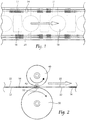
- Fig. 1 a top view of a pant type diaper during production is shown.
- Elastic strands 14 are laid down over areas with adhesive 12 and without adhesive between areas of adhesive 12, in what will become front and rear portions of the diaper.
- adhesive 12 is laid down with an intermittent adhesive applicator which is turned on and off as the web 22 migrates downstream, to create the zones of adhesive 12.
- an absorbent core 16, leg cut outs 18, and side seam cuts 20 are provided to achieve the final diaper product after folding (not shown).
- Strands 14, ribbon, scrim, or a continuous layer of elastic can all be employed interchangeably.
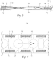
- Knife roll 40 carries knife 42 on knife insert 44.
- Anvil roll 50 carries a variable interference anvil 52.
- the knife roll 40 rotates in a counterclockwise direction, and the anvil roll 50 rotates in a clockwise direction.
- the force of the knife 42 on the variable interference anvil 52 is enough to sever the elastic 14, but preferably not enough to sever nonwovens 22.
- the elastic 14 snaps out of zones without adhesive 12 leaving severed elastic 14', but elastic 14 remains in place in zones with adhesive 12 to provide elasticity in those zones.
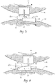
- the rotating profiled knife 42 is shown, preferably with a relatively blunt tip or edge 43 to avoid or minimize severing nonwoven 22.
- a radius R 1 of approximately 0.25 - 10.0 mm can be used at the knife tip or blade edge 43, but more preferably, a radius R1 of approximately 0.25 - 6.0 mm may be used.
- Variable interference anvil 52 has a working anvil surface 51 is sloped between a lower trailing end 53 and a higher leading end 55. Between the ends 53,55, the working anvil surface has a length 57 measured parallel to a tangent of the revolutional path of the anvil 52.
- the slope of the anvil 52 preferably forms a linear relationship with the nip gap between knife 42 and anvil 52. For instance, for every millimeter along the length 57, a change in approximately 0.0005" of a nip gap ( ⁇ ) between knife 42 and anvil 52 is provided. That is, when the knife edge 43 is closest to the anvil axis, the knife 42 and anvil 52 may be said to be in a nip position.
- the gap ⁇ 1 can be varied. For instance, as shown in Fig. 5 , the knife 42 is positioned relatively near the trailing end 53 of the anvil 52, creating a larger gap ⁇ 1. By positioning knife 42 relatively near the leading end 55 of the anvil 52, a smaller gap ⁇ 2 is provided as shown in Fig. 6 .
- a slightly larger gap ⁇ 1 because less interference is required to deactivate elastic 14.
- a smaller gap ⁇ 2 may be desired. In other words, deactivation of elastics 14 requires less force at higher speeds, so the slightly larger gap ⁇ 1 is preferred to minimize disruption of the nonwoven layers 22.
- Phase adjustments (relative rotational positioning) between knife 42 and anvil 52 can be varied to provide the right impact at a given speed.
- Rotational positioning of the knife roll 40 (and thus the knife blade 43) relative to the anvil surface 51 is done programmatically, by controlling servo dive motors that drive the rolls 40,50 respectively. Adjustments may be made based on thickness 32 of elastics 14 or a thickness 34 of a composite web including the material members to be severed. In this way, accommodations may be made for machine speed or even variations or wear of components. For instance, if the blade 42 is wearing some, the knife 42 can be shifted to a relatively higher point on anvil 52 to return to the desired gap ⁇ .
- Knife inserts 44 carry knives 42.
- An operator side and a drive side knife insert 44 are provided, in order to create the severs in elastic 14, for instance near the side seam cuts 20 of Fig. 1 , but preferably between adhesive 12 zones on both the front and rear of the diaper product.
- the inserts 44 can be aligned in the machine direction.
- the knife inserts 44 can be offset in the machine direction by a distance ⁇ 2 in order to contact the elastics 14 at different times during the manufacturing process, if desired.
Landscapes
- Life Sciences & Earth Sciences (AREA)
- Forests & Forestry (AREA)
- Engineering & Computer Science (AREA)
- Mechanical Engineering (AREA)
- Absorbent Articles And Supports Therefor (AREA)
- Perforating, Stamping-Out Or Severing By Means Other Than Cutting (AREA)
- Laminated Bodies (AREA)
- Lining Or Joining Of Plastics Or The Like (AREA)
Claims (15)
- Vorrichtung, die Folgendes umfasst:eine Klingenwalzeneinheit (40), die für eine Drehung in eine erste Richtung um eine erste Achse herum gelagert ist, wobei die Klingenwalzeneinheit (40) eine profilierte Klinge (42) darauf trägt, die sich mit der Klingenwalzeneinheit (40) dreht;eine Ambosswalzeneinheit (50), die für die Drehung in eine zweite Richtung um eine zweite Achse herum gelagert ist, wobei die Ambosswalzeneinheit (50) eine Arbeitsambossoberfläche (51) trägt, wobei die Klingenwalzeneinheit und die Ambosswalzeneinheit derart angeordnet sind, dass die Drehung dieser die profilierte Klinge in die Nähe der Arbeitsambossoberfläche bringt, um einen Spalt dazwischen zum Aufnehmen eines Gewebematerials zu definieren, dadurch gekennzeichnet, dass die Arbeitsambossoberfläche (51) von einem höheren vorderen Ende (55) zu einem niedrigeren hinteren Ende (53) zu der zweiten Achse hin geneigt ist und dadurch, dass die Vorrichtung Servomotoren umfasst, die für Folgendes konfiguriert sind:
(i) Drehen der Klingenwalzeneinheit (40) in die erste Richtung und der Ambosswalzeneinheit (50) in die zweite Richtung und (ii) Steuern des Drehpositionierens der Klingenwalzeneinheit (40) relativ zu der Ambosswalzeneinheit (50), wobei dadurch das Positionieren der profilierten Klinge (42) relativ zu der Arbeitsambossoberfläche (51) und eine Breite des Spaltes zwischen der profilierten Klinge und der Arbeitsambossoberfläche gesteuert wird. - Vorrichtung nach Anspruch 1, die konfiguriert ist, sodass in Verwendung die profilierte Klinge (42) eine Drehposition aufweist, in der sie der Arbeitsambossoberfläche (51) am nächsten ist, um eine Kraft auf die Arbeitsambossoberfläche (51) auszuüben, während sich die profilierte Klinge (42) und die Arbeitsambossoberfläche (51) aneinander vorbei drehen.
- Vorrichtung nach Anspruch 2, wobei die Servomotoren das Positionieren der profilierten Klinge (42) relativ zu der Arbeitsambossoberfläche (51) steuern, um einen Kraftbetrag zu steuern, der durch die profilierte Klinge (42) auf die Arbeitsambossoberfläche (51) ausgeübt wird, während sich die profilierte Klinge (42) und die Arbeitsambossoberfläche (51) aneinander vorbei drehen.
- Vorrichtung nach Anspruch 2, die zur Verwendung mit einem Material geeignet ist, das elastische Stränge (14) umfasst, die zwischen einem Paar von Vliesschichten (22) liegen.
- Vorrichtung nach Anspruch 4, die konfiguriert ist, sodass in Verwendung die durch die profilierte Klinge (42) auf die Arbeitsambossoberfläche (51) ausgeübte Kraft ausreicht, um die elastischen Stränge (14) zu trennen, während das Paar von Vliesschichten (22) intakt gelassen wird.
- Vorrichtung nach Anspruch 1, wobei die Arbeitsambossoberfläche (51) einen Drehweg der Ambosswalzeneinheit (50) tangiert.
- Vorrichtung nach Anspruch 1, wobei die erste Achse und die zweite Achse wenigstens im Wesentlichen parallel zueinander sind.
- Vorrichtung nach Anspruch 1, wobei in Verwendung beim Steuern des Drehpositionierens der Klingenwalzeneinheit (40) relativ zu der Ambosswalzeneinheit (50) die Servomotoren eine Phaseneinstellung zwischen der Klingenwalzeneinheit (40) und der Ambosswalzeneinheit (50) bereitstellen.
- Vorrichtung nach Anspruch 1, wobei die Klingenwalzeneinheit (40) ein Paar profilierter Klingen (42) trägt, die eine bedienerseitige profilierte Klinge (42) und eine antriebsseitige profilierte Klinge (42) umfassen, wobei das Paar profilierter Klingen (42) nebeneinander angeordnet positioniert ist und entweder in einer Maschinenrichtung ausgerichtet oder in der Maschinenrichtung versetzt ist.
- Verfahren zum Bedienen eines Systems, das Folgendes aufweist:eine Klingenwalzeneinheit (40), die sich in eine erste Richtung um eine erste Achse herum dreht und eine profilierte Klinge (42) darauf trägt; undeine Ambosswalzeneinheit (50), die sich in eine zweite Richtung um eine zweite Achse herum dreht und eine Arbeitsambossoberfläche (51) trägt, die von der zweiten Achse abgewandt ist, wobei die Klingenwalzeneinheit und die Ambosswalzeneinheit derart angeordnet sind, dass die Drehung dieser die profilierte Klinge in die Nähe der Arbeitsambossoberfläche bringt, um einen Spalt dazwischen zum Aufnehmen eines Laminats zu definieren, das ein zwischen zwei Materialschichten liegendes dehnbares Gummiband umfasst, dadurch gekennzeichnet, dass das Verfahren Folgendes umfasst:Verwenden einer Arbeitsambossoberfläche, die von einem höheren vorderen Ende (55) zu einem niedrigeren hinteren Ende (53) zu der zweiten Achse hin geneigt ist;Verwenden von Servomotoren, um die Klingenwalzeneinheit (40) in die erste Richtung und die Ambosswalzeneinheit (50) in die zweite Richtung anzutreiben; undBedienen der Servomotoren, um das Drehpositionieren der Klingenwalzeneinheit (40) relativ zu der Ambosswalzeneinheit (50) zu steuern, um das Positionieren der profilierten Klinge (42) relativ zu der Arbeitsambossoberfläche (51) zu steuern, und wobei dadurch eine Breite des Spaltes zwischen der profilierten Klinge (42) und der Arbeitsambossoberfläche (51) gesteuert wird, während sich die profilierte Klinge (42) und die Arbeitsambossoberfläche (51) aneinander vorbei drehen.
- Verfahren nach Anspruch 10, wobei das Steuern der Breite des Spaltes zwischen der profilierten Klinge (42) und der Arbeitsambossoberfläche (51) die Kraft steuert, die auf das Laminat ausgeübt wird, das zwischen der profilierten Klinge (42) und der Arbeitsambossoberfläche (51) geführt wird, während sich die profilierte Klinge (42) und die Arbeitsambossoberfläche (51) aneinander vorbei drehen.
- Verfahren nach Anspruch 11, das das Führen eines Laminats zwischen der Klingenwalzeneinheit (40) und der Ambosswalzeneinheit (50) umfasst, wobei das Laminat ein Paar von Vliesschichten (22) mit dazwischen liegenden elastischen Strängen 14) umfasst.
- Verfahren nach Anspruch 12, das das Bedienen der Servomotoren derart umfasst, dass die durch die profilierte Klinge (42) auf die Arbeitsambossoberfläche (51) ausgeübte Kraft ausreicht, um die elastischen Stränge (14) zu trennen, aber das Paar von Vliesschichten (22) intakt zu lassen.
- Verfahren nach Anspruch 12, das ferner ein Variieren des Positionierens der profilierten Klinge (42) relativ zu der Arbeitsambossoberfläche (51) basierend auf einer Dicke des Laminats, Drehzahlen der Klingenwalzeneinheit (40) und der Ambosswalzeneinheit (50) und/oder ein Verschleißen der profilierten Klinge (42) umfasst.
- Verfahren nach Anspruch 10, wobei das Steuern des Drehpositionierens der Klingenwalzeneinheit (40) relativ zu der Ambosswalzeneinheit (50) das Bedienen der Servomotoren umfasst, um eine Phaseneinstellung zwischen der Klingenwalzeneinheit (40) und der Ambosswalzeneinheit (50) bereitzustellen.
Priority Applications (1)
| Application Number | Priority Date | Filing Date | Title |
|---|---|---|---|
| PL19160263T PL3521024T3 (pl) | 2014-06-11 | 2015-06-11 | Sposób i oprzyrządowanie do eliminowania sprężystości taśmy gumowej w laminacie |
Applications Claiming Priority (3)
| Application Number | Priority Date | Filing Date | Title |
|---|---|---|---|
| US201462010758P | 2014-06-11 | 2014-06-11 | |
| EP15805755.4A EP3154788B1 (de) | 2014-06-11 | 2015-06-11 | Verfahren und vorrichtung für elastische deaktivierung in einem laminat |
| PCT/US2015/035404 WO2015191904A1 (en) | 2014-06-11 | 2015-06-11 | Methods and apparatus for elastic deactivation in a laminate |
Related Parent Applications (1)
| Application Number | Title | Priority Date | Filing Date |
|---|---|---|---|
| EP15805755.4A Division EP3154788B1 (de) | 2014-06-11 | 2015-06-11 | Verfahren und vorrichtung für elastische deaktivierung in einem laminat |
Publications (2)
| Publication Number | Publication Date |
|---|---|
| EP3521024A1 EP3521024A1 (de) | 2019-08-07 |
| EP3521024B1 true EP3521024B1 (de) | 2021-06-02 |
Family
ID=54834343
Family Applications (2)
| Application Number | Title | Priority Date | Filing Date |
|---|---|---|---|
| EP19160263.0A Active EP3521024B1 (de) | 2014-06-11 | 2015-06-11 | Verfahren und vorrichtung für elastische deaktivierung in einem laminat |
| EP15805755.4A Active EP3154788B1 (de) | 2014-06-11 | 2015-06-11 | Verfahren und vorrichtung für elastische deaktivierung in einem laminat |
Family Applications After (1)
| Application Number | Title | Priority Date | Filing Date |
|---|---|---|---|
| EP15805755.4A Active EP3154788B1 (de) | 2014-06-11 | 2015-06-11 | Verfahren und vorrichtung für elastische deaktivierung in einem laminat |
Country Status (11)
| Country | Link |
|---|---|
| US (2) | US9539735B2 (de) |
| EP (2) | EP3521024B1 (de) |
| BR (1) | BR112016028976B1 (de) |
| CA (1) | CA2950599C (de) |
| DK (2) | DK3521024T3 (de) |
| ES (2) | ES2720269T3 (de) |
| MA (2) | MA46382A (de) |
| MX (1) | MX380888B (de) |
| PL (2) | PL3521024T3 (de) |
| TR (1) | TR201905622T4 (de) |
| WO (1) | WO2015191904A1 (de) |
Families Citing this family (32)
| Publication number | Priority date | Publication date | Assignee | Title |
|---|---|---|---|---|
| US11254024B2 (en) | 2013-06-12 | 2022-02-22 | The Procter & Gamble Company | Method of perforating a nonlinear line of weakness |
| MX2015017172A (es) | 2013-06-12 | 2016-03-16 | Procter & Gamble | Una linea de rasgadura no lineal formada por un aparato perforador. |
| WO2015160388A1 (en) * | 2014-04-16 | 2015-10-22 | Westrock Mwv, Llc | Three dimensional part rotary die cutting mechanism and method of operating the same |
| US10792194B2 (en) | 2014-08-26 | 2020-10-06 | Curt G. Joa, Inc. | Apparatus and methods for securing elastic to a carrier web |
| WO2016148899A1 (en) | 2015-03-17 | 2016-09-22 | The Procter & Gamble Company | Apparatus for perforating a web material |
| WO2016148900A1 (en) | 2015-03-17 | 2016-09-22 | The Procter & Gamble Company | Apparatus for perforating a nonlinear line of weakness |
| WO2016148894A1 (en) | 2015-03-17 | 2016-09-22 | The Procter & Gamble Company | Method for perforating a nonlinear line of weakness |
| EP3246140B1 (de) * | 2016-05-16 | 2019-06-26 | Tetra Laval Holdings & Finance S.A. | Schneideeinheit und schneidverfahren |
| EP3246138B1 (de) * | 2016-05-16 | 2020-05-06 | Tetra Laval Holdings & Finance S.A. | Schneidsystem und verfahren zum schneiden einer bahn oder materialbahn |
| EP3246139B1 (de) * | 2016-05-16 | 2020-09-30 | Tetra Laval Holdings & Finance S.A. | Schneidwerkzeug und verfahren zum schneiden einer materialbahn oder -folie |
| CN106272695B (zh) * | 2016-08-26 | 2018-04-10 | 松嘉(泉州)机械有限公司 | 一种纸尿裤耳片短切装置 |
| WO2018106160A1 (en) * | 2016-12-05 | 2018-06-14 | Sca Hygiene Products Ab | A disposable pant-type absorbent article |
| US11642249B2 (en) | 2016-12-20 | 2023-05-09 | The Procter & Gamble Company | Methods and apparatuses for making elastomeric laminates with elastic strands provided with a spin finish |
| WO2018208311A1 (en) * | 2017-05-12 | 2018-11-15 | Delta Systems & Automation Inc. | Head for horizontal flow wrapper packaging machine |
| WO2019046363A1 (en) | 2017-09-01 | 2019-03-07 | The Procter & Gamble Company | METHODS AND APPARATUS FOR THE PRODUCTION OF ELASTOMERIC LAMINATES |
| US11147718B2 (en) | 2017-09-01 | 2021-10-19 | The Procter & Gamble Company | Beamed elastomeric laminate structure, fit, and texture |
| US11008709B2 (en) | 2017-09-11 | 2021-05-18 | The Procter & Gamble Company | Sanitary tissue product with a shaped line of weakness |
| US11806889B2 (en) | 2017-09-11 | 2023-11-07 | The Procter & Gamble Company | Perforating apparatus and method for manufacturing a shaped line of weakness |
| US11806890B2 (en) | 2017-09-11 | 2023-11-07 | The Procter & Gamble Company | Perforating apparatus and method for manufacturing a shaped line of weakness |
| US11547613B2 (en) | 2017-12-05 | 2023-01-10 | The Procter & Gamble Company | Stretch laminate with beamed elastics and formed nonwoven layer |
| US10765565B2 (en) | 2018-01-25 | 2020-09-08 | The Procter & Gamble Company | Method for manufacturing topsheets for absorbent articles |
| JP7791651B2 (ja) | 2018-01-29 | 2025-12-24 | カート ジー.ジョア、インコーポレイテッド | 吸収性衛生製品用の弾性複合材構造体を製造する装置および方法 |
| EP3810056B1 (de) | 2018-06-19 | 2025-01-08 | The Procter & Gamble Company | Saugfähiger artikel mit funktionsgeformter deckschicht und verfahren zu seiner herstellung |
| US11925538B2 (en) | 2019-01-07 | 2024-03-12 | Curt G. Joa, Inc. | Apparatus and method of manufacturing an elastic composite structure for an absorbent sanitary product |
| US12053357B2 (en) | 2019-06-19 | 2024-08-06 | The Procter & Gamble Company | Absorbent article with function-formed topsheet, and method for manufacturing |
| US11819393B2 (en) | 2019-06-19 | 2023-11-21 | The Procter & Gamble Company | Absorbent article with function-formed topsheet, and method for manufacturing |
| US12433797B2 (en) | 2019-09-04 | 2025-10-07 | Curt G. Joa, Inc. | Elastic entrapment with waist cap bonding |
| US11173072B2 (en) | 2019-09-05 | 2021-11-16 | Curt G. Joa, Inc. | Curved elastic with entrapment |
| WO2021168473A1 (en) | 2020-02-17 | 2021-08-26 | Curt G. Joa, Inc. | An elastic composite structure for an absorbent sanitary product and an apparatus and method for making said elastic composite structure |
| CN117283944A (zh) | 2020-03-13 | 2023-12-26 | 宝洁公司 | 梁式弹性体层合物性能和区域 |
| US11618177B1 (en) | 2022-04-12 | 2023-04-04 | Bradley W Boesel | Orbital knife |
| WO2026050040A1 (en) | 2024-08-27 | 2026-03-05 | Curt G. Joa, Inc. | Refastenable pant with hook on insert and method of producing refastenable pant |
Family Cites Families (48)
| Publication number | Priority date | Publication date | Assignee | Title |
|---|---|---|---|---|
| US2139890A (en) * | 1936-06-13 | 1938-12-13 | F X Hooper Company Inc | Creaser |
| US3174372A (en) * | 1962-03-19 | 1965-03-23 | William F Huck | High speed web cutting and delivery machine |
| US3716132A (en) * | 1970-11-20 | 1973-02-13 | Scott Paper Co | Thread-reinforced laminated structure having lines of weakness and method and apparatus for creating lines of weakness |
| US3827340A (en) * | 1971-08-06 | 1974-08-06 | Ludlow Corp | Fracturable adhesive backing tool |
| US3850059A (en) * | 1973-01-08 | 1974-11-26 | Chempar Corp | Die and method for cutting labels and the like |
| US3965786A (en) * | 1974-07-16 | 1976-06-29 | Moore Business Forms, Inc. | Rotary die cutter |
| US4289055A (en) * | 1980-01-07 | 1981-09-15 | Von Schriltz Don F | Rotary die anvil |
| US4412467A (en) * | 1981-09-14 | 1983-11-01 | Lehigh Steck Warlick | Cylinder-mounted cutter |
| US4417883A (en) * | 1981-11-05 | 1983-11-29 | United States Gypsum Company | Apparatus for creasing paper used in the production of gypsum wallboard |
| FR2539274A1 (fr) | 1983-01-19 | 1984-07-20 | Boussac Saint Freres Bsf | Procede de fabrication de couches-culottes a jeter et couches-culottes obtenues |
| US4491045A (en) | 1983-04-15 | 1985-01-01 | Scott Paper Company | Rotary cutter for thin, flexible webs |
| US4936818A (en) * | 1989-03-27 | 1990-06-26 | Holohan Jr Joseph | Paper scoring device |
| CH690958A5 (fr) * | 1995-04-15 | 2001-03-15 | Bobst Sa | Installation de découpage rotatif. |
| AU8745391A (en) * | 1990-09-27 | 1992-04-28 | Computype, Inc. | Rotary die cutting mechanism |
| MY109047A (en) | 1990-10-31 | 1996-11-30 | Kao Corp | Disposable diaper |
| US5129435A (en) * | 1990-11-15 | 1992-07-14 | Masonite Corporation | Apparatus and method for improving fiberboard mat moldability |
| US5083488A (en) * | 1991-04-12 | 1992-01-28 | Melvin Stanley | Radially adjustable anvil roll assembly for a rotary die cutting press |
| US5156076A (en) * | 1991-05-21 | 1992-10-20 | Rosemann Richard R | Radially adjustable anvil roll assembly for a rotary die cutting press |
| US5158525A (en) * | 1992-01-22 | 1992-10-27 | Westvaco Corporation | Adjustable wear pads for slotting head yoke plates |
| SE508409C2 (sv) | 1992-03-04 | 1998-10-05 | Sca Hygiene Prod Ab | Absorberande blöjbyxor |
| US5660657A (en) | 1995-01-31 | 1997-08-26 | Kimberly-Clark Worldwide, Inc. | Composite method for fabricating garments |
| US5745922A (en) | 1995-01-31 | 1998-05-05 | Kimberly Clark Corporation | Disposable garment and related manufacturing equipment and methods |
| US5707470A (en) | 1995-01-31 | 1998-01-13 | Kimberly-Clark Worldwide, Inc. | Rotary ultrasonic apparatus and methods |
| US5873807A (en) * | 1995-03-20 | 1999-02-23 | Corrugated Gear & Services, Inc. | Scoring assembly |
| US6551430B1 (en) | 1995-05-31 | 2003-04-22 | Kimberly-Clark Worldwide, Inc. | Process for making a training pant having a unitary waist elastic system |
| FR2745987B1 (fr) * | 1996-03-15 | 1998-06-12 | Coulisse de froncage et son procede de fabrication | |
| JPH1177586A (ja) * | 1997-09-04 | 1999-03-23 | Mitsubishi Heavy Ind Ltd | ロータリカットオフ装置 |
| US6244151B1 (en) * | 1998-06-11 | 2001-06-12 | Tamarack Products Inc. | Apparatus for adjusting cutting bar |
| JP4421012B2 (ja) | 1999-06-16 | 2010-02-24 | 株式会社瑞光 | 使い捨てパンツ及びその製造方法 |
| US6482278B1 (en) | 2000-03-29 | 2002-11-19 | Curt G. Joa, Inc. | Pants type diaper and method for producing same |
| CA2402778A1 (en) * | 2000-04-03 | 2001-10-11 | Reese Products, Inc. | Trailer hitch assembly with accessory ports |
| US20020046802A1 (en) | 2000-08-04 | 2002-04-25 | Ikuo Tachibana | Method for manufacturing disposable worn article |
| US20060254698A1 (en) | 2000-04-08 | 2006-11-16 | Zuiko Corporation | Method for manufacturing disposable worn article |
| US6517650B2 (en) * | 2000-11-30 | 2003-02-11 | Kimberly-Clark Worldwide, Inc. | Ultrasonic bonding apparatus and methods |
| WO2002074213A1 (en) | 2001-03-15 | 2002-09-26 | Daio Paper Corporation | Paper diaper and method for manufacturing extensible sheet used in the diaper |
| US6913673B2 (en) * | 2001-12-19 | 2005-07-05 | Kimberly-Clark Worldwide, Inc. | Heated embossing and ply attachment |
| US20040074352A1 (en) * | 2002-10-21 | 2004-04-22 | Kimberly-Clark Worldwide, Inc. | Adjustable anvil for a flat bearer ring die |
| US20050230037A1 (en) | 2004-04-20 | 2005-10-20 | Curt G. Joa, Inc. | Staggered cutting knife |
| US7708849B2 (en) | 2004-04-20 | 2010-05-04 | Curt G. Joa, Inc. | Apparatus and method for cutting elastic strands between layers of carrier webs |
| US7638014B2 (en) | 2004-05-21 | 2009-12-29 | Curt G. Joa, Inc. | Method of producing a pants-type diaper |
| US8621966B2 (en) * | 2008-03-18 | 2014-01-07 | Kimberly-Clark Worldwide, Inc. | Perforation anvil |
| JP5469902B2 (ja) | 2009-04-03 | 2014-04-16 | ユニ・チャーム株式会社 | シートの製造方法、吸収性物品に係る資材の製造方法、及びシートの製造装置 |
| JP5517536B2 (ja) * | 2009-09-18 | 2014-06-11 | ユニ・チャーム株式会社 | 裁断装置 |
| US9028632B2 (en) | 2012-03-30 | 2015-05-12 | The Procter & Gamble Company | Apparatuses and methods for making absorbent articles |
| US20130255861A1 (en) | 2012-03-30 | 2013-10-03 | Uwe Schneider | Apparatuses and Methods for Making Absorbent Articles |
| US9050213B2 (en) | 2012-03-30 | 2015-06-09 | The Procter & Gamble Company | Apparatuses and methods for making absorbent articles |
| US8440043B1 (en) * | 2012-03-30 | 2013-05-14 | The Procter & Gamble Company | Absorbent article process and apparatus for intermittently deactivating elastics in elastic laminates |
| US9039855B2 (en) | 2012-03-30 | 2015-05-26 | The Procter & Gamble Company | Apparatuses and methods for making absorbent articles |
-
2015
- 2015-06-11 DK DK19160263.0T patent/DK3521024T3/da active
- 2015-06-11 EP EP19160263.0A patent/EP3521024B1/de active Active
- 2015-06-11 PL PL19160263T patent/PL3521024T3/pl unknown
- 2015-06-11 PL PL15805755T patent/PL3154788T3/pl unknown
- 2015-06-11 WO PCT/US2015/035404 patent/WO2015191904A1/en not_active Ceased
- 2015-06-11 CA CA2950599A patent/CA2950599C/en active Active
- 2015-06-11 TR TR2019/05622T patent/TR201905622T4/tr unknown
- 2015-06-11 MA MA046382A patent/MA46382A/fr unknown
- 2015-06-11 MX MX2016015671A patent/MX380888B/es unknown
- 2015-06-11 BR BR112016028976-5A patent/BR112016028976B1/pt not_active IP Right Cessation
- 2015-06-11 DK DK15805755.4T patent/DK3154788T3/da active
- 2015-06-11 ES ES15805755T patent/ES2720269T3/es active Active
- 2015-06-11 EP EP15805755.4A patent/EP3154788B1/de active Active
- 2015-06-11 US US14/737,272 patent/US9539735B2/en not_active Expired - Fee Related
- 2015-06-11 ES ES19160263T patent/ES2878140T3/es active Active
- 2015-06-11 MA MA040230A patent/MA40230A/fr unknown
-
2017
- 2017-01-09 US US15/401,511 patent/US10391657B2/en active Active
Non-Patent Citations (1)
| Title |
|---|
| None * |
Also Published As
| Publication number | Publication date |
|---|---|
| WO2015191904A1 (en) | 2015-12-17 |
| TR201905622T4 (tr) | 2019-05-21 |
| ES2878140T3 (es) | 2021-11-18 |
| US10391657B2 (en) | 2019-08-27 |
| MA40230A (fr) | 2017-04-19 |
| ES2720269T3 (es) | 2019-07-19 |
| CA2950599C (en) | 2019-01-22 |
| EP3154788A1 (de) | 2017-04-19 |
| PL3154788T3 (pl) | 2019-07-31 |
| US9539735B2 (en) | 2017-01-10 |
| MA46382A (fr) | 2019-08-07 |
| BR112016028976A2 (pt) | 2018-06-19 |
| EP3521024A1 (de) | 2019-08-07 |
| BR112016028976B1 (pt) | 2021-10-19 |
| DK3521024T3 (en) | 2021-06-14 |
| DK3154788T3 (da) | 2019-05-06 |
| US20170113366A1 (en) | 2017-04-27 |
| EP3154788B1 (de) | 2019-03-06 |
| MX2016015671A (es) | 2017-08-21 |
| MX380888B (es) | 2025-03-12 |
| PL3521024T3 (pl) | 2021-12-13 |
| US20150360380A1 (en) | 2015-12-17 |
| EP3154788A4 (de) | 2018-03-07 |
| CA2950599A1 (en) | 2015-12-17 |
Similar Documents
| Publication | Publication Date | Title |
|---|---|---|
| EP3521024B1 (de) | Verfahren und vorrichtung für elastische deaktivierung in einem laminat | |
| US11639282B2 (en) | Apparatus and method for applying parallel flared elastics to disposable products and disposable products containing parallel flared elastics | |
| US11331223B2 (en) | Methods and apparatuses for assembling elastic laminates with different bond densities for absorbent articles | |
| EP2446868A1 (de) | Vorrichtung und Verfahren zur Anwendung eines gekrümmten Bandes einer laufenden Bahn | |
| EP2345395A1 (de) | Vorrichtung und Verfahren zur Herstellung absorbierender Artikel mit Dehnfolienseitenwand und Anwendung einer intermittierenden diskreten Komponente eines absorbierenden Artikels | |
| EP3533428B1 (de) | Vorrichtung zum auftragen von gummibänder auf einwegprodukte | |
| CA2852473C (en) | Method for producing an absorbent article comprising stretch film side panel and core inserts |
Legal Events
| Date | Code | Title | Description |
|---|---|---|---|
| PUAI | Public reference made under article 153(3) epc to a published international application that has entered the european phase |
Free format text: ORIGINAL CODE: 0009012 |
|
| STAA | Information on the status of an ep patent application or granted ep patent |
Free format text: STATUS: REQUEST FOR EXAMINATION WAS MADE |
|
| 17P | Request for examination filed |
Effective date: 20190301 |
|
| AC | Divisional application: reference to earlier application |
Ref document number: 3154788 Country of ref document: EP Kind code of ref document: P |
|
| AK | Designated contracting states |
Kind code of ref document: A1 Designated state(s): AL AT BE BG CH CY CZ DE DK EE ES FI FR GB GR HR HU IE IS IT LI LT LU LV MC MK MT NL NO PL PT RO RS SE SI SK SM TR |
|
| AX | Request for extension of the european patent |
Extension state: BA ME |
|
| GRAP | Despatch of communication of intention to grant a patent |
Free format text: ORIGINAL CODE: EPIDOSNIGR1 |
|
| STAA | Information on the status of an ep patent application or granted ep patent |
Free format text: STATUS: GRANT OF PATENT IS INTENDED |
|
| INTG | Intention to grant announced |
Effective date: 20200708 |
|
| GRAJ | Information related to disapproval of communication of intention to grant by the applicant or resumption of examination proceedings by the epo deleted |
Free format text: ORIGINAL CODE: EPIDOSDIGR1 |
|
| STAA | Information on the status of an ep patent application or granted ep patent |
Free format text: STATUS: REQUEST FOR EXAMINATION WAS MADE |
|
| INTC | Intention to grant announced (deleted) | ||
| GRAP | Despatch of communication of intention to grant a patent |
Free format text: ORIGINAL CODE: EPIDOSNIGR1 |
|
| STAA | Information on the status of an ep patent application or granted ep patent |
Free format text: STATUS: GRANT OF PATENT IS INTENDED |
|
| INTG | Intention to grant announced |
Effective date: 20210113 |
|
| GRAS | Grant fee paid |
Free format text: ORIGINAL CODE: EPIDOSNIGR3 |
|
| GRAA | (expected) grant |
Free format text: ORIGINAL CODE: 0009210 |
|
| STAA | Information on the status of an ep patent application or granted ep patent |
Free format text: STATUS: THE PATENT HAS BEEN GRANTED |
|
| REG | Reference to a national code |
Ref country code: CH Ref legal event code: EP |
|
| AC | Divisional application: reference to earlier application |
Ref document number: 3154788 Country of ref document: EP Kind code of ref document: P |
|
| AK | Designated contracting states |
Kind code of ref document: B1 Designated state(s): AL AT BE BG CH CY CZ DE DK EE ES FI FR GB GR HR HU IE IS IT LI LT LU LV MC MK MT NL NO PL PT RO RS SE SI SK SM TR |
|
| REG | Reference to a national code |
Ref country code: GB Ref legal event code: FG4D |
|
| REG | Reference to a national code |
Ref country code: DK Ref legal event code: T3 Effective date: 20210610 |
|
| REG | Reference to a national code |
Ref country code: AT Ref legal event code: REF Ref document number: 1398063 Country of ref document: AT Kind code of ref document: T Effective date: 20210615 |
|
| REG | Reference to a national code |
Ref country code: IE Ref legal event code: FG4D |
|
| REG | Reference to a national code |
Ref country code: DE Ref legal event code: R096 Ref document number: 602015070156 Country of ref document: DE |
|
| REG | Reference to a national code |
Ref country code: SE Ref legal event code: TRGR |
|
| REG | Reference to a national code |
Ref country code: NL Ref legal event code: FP |
|
| REG | Reference to a national code |
Ref country code: LT Ref legal event code: MG9D |
|
| PG25 | Lapsed in a contracting state [announced via postgrant information from national office to epo] |
Ref country code: BG Free format text: LAPSE BECAUSE OF FAILURE TO SUBMIT A TRANSLATION OF THE DESCRIPTION OR TO PAY THE FEE WITHIN THE PRESCRIBED TIME-LIMIT Effective date: 20210902 Ref country code: LT Free format text: LAPSE BECAUSE OF FAILURE TO SUBMIT A TRANSLATION OF THE DESCRIPTION OR TO PAY THE FEE WITHIN THE PRESCRIBED TIME-LIMIT Effective date: 20210602 Ref country code: HR Free format text: LAPSE BECAUSE OF FAILURE TO SUBMIT A TRANSLATION OF THE DESCRIPTION OR TO PAY THE FEE WITHIN THE PRESCRIBED TIME-LIMIT Effective date: 20210602 Ref country code: FI Free format text: LAPSE BECAUSE OF FAILURE TO SUBMIT A TRANSLATION OF THE DESCRIPTION OR TO PAY THE FEE WITHIN THE PRESCRIBED TIME-LIMIT Effective date: 20210602 |
|
| REG | Reference to a national code |
Ref country code: AT Ref legal event code: MK05 Ref document number: 1398063 Country of ref document: AT Kind code of ref document: T Effective date: 20210602 |
|
| REG | Reference to a national code |
Ref country code: ES Ref legal event code: FG2A Ref document number: 2878140 Country of ref document: ES Kind code of ref document: T3 Effective date: 20211118 |
|
| PG25 | Lapsed in a contracting state [announced via postgrant information from national office to epo] |
Ref country code: GR Free format text: LAPSE BECAUSE OF FAILURE TO SUBMIT A TRANSLATION OF THE DESCRIPTION OR TO PAY THE FEE WITHIN THE PRESCRIBED TIME-LIMIT Effective date: 20210903 Ref country code: LV Free format text: LAPSE BECAUSE OF FAILURE TO SUBMIT A TRANSLATION OF THE DESCRIPTION OR TO PAY THE FEE WITHIN THE PRESCRIBED TIME-LIMIT Effective date: 20210602 Ref country code: NO Free format text: LAPSE BECAUSE OF FAILURE TO SUBMIT A TRANSLATION OF THE DESCRIPTION OR TO PAY THE FEE WITHIN THE PRESCRIBED TIME-LIMIT Effective date: 20210902 Ref country code: RS Free format text: LAPSE BECAUSE OF FAILURE TO SUBMIT A TRANSLATION OF THE DESCRIPTION OR TO PAY THE FEE WITHIN THE PRESCRIBED TIME-LIMIT Effective date: 20210602 |
|
| PG25 | Lapsed in a contracting state [announced via postgrant information from national office to epo] |
Ref country code: AT Free format text: LAPSE BECAUSE OF FAILURE TO SUBMIT A TRANSLATION OF THE DESCRIPTION OR TO PAY THE FEE WITHIN THE PRESCRIBED TIME-LIMIT Effective date: 20210602 Ref country code: RO Free format text: LAPSE BECAUSE OF FAILURE TO SUBMIT A TRANSLATION OF THE DESCRIPTION OR TO PAY THE FEE WITHIN THE PRESCRIBED TIME-LIMIT Effective date: 20210602 Ref country code: PT Free format text: LAPSE BECAUSE OF FAILURE TO SUBMIT A TRANSLATION OF THE DESCRIPTION OR TO PAY THE FEE WITHIN THE PRESCRIBED TIME-LIMIT Effective date: 20211004 Ref country code: SM Free format text: LAPSE BECAUSE OF FAILURE TO SUBMIT A TRANSLATION OF THE DESCRIPTION OR TO PAY THE FEE WITHIN THE PRESCRIBED TIME-LIMIT Effective date: 20210602 Ref country code: EE Free format text: LAPSE BECAUSE OF FAILURE TO SUBMIT A TRANSLATION OF THE DESCRIPTION OR TO PAY THE FEE WITHIN THE PRESCRIBED TIME-LIMIT Effective date: 20210602 Ref country code: SK Free format text: LAPSE BECAUSE OF FAILURE TO SUBMIT A TRANSLATION OF THE DESCRIPTION OR TO PAY THE FEE WITHIN THE PRESCRIBED TIME-LIMIT Effective date: 20210602 |
|
| REG | Reference to a national code |
Ref country code: CH Ref legal event code: PL |
|
| REG | Reference to a national code |
Ref country code: DE Ref legal event code: R097 Ref document number: 602015070156 Country of ref document: DE |
|
| PG25 | Lapsed in a contracting state [announced via postgrant information from national office to epo] |
Ref country code: MC Free format text: LAPSE BECAUSE OF FAILURE TO SUBMIT A TRANSLATION OF THE DESCRIPTION OR TO PAY THE FEE WITHIN THE PRESCRIBED TIME-LIMIT Effective date: 20210602 Ref country code: LU Free format text: LAPSE BECAUSE OF NON-PAYMENT OF DUE FEES Effective date: 20210611 |
|
| PLBE | No opposition filed within time limit |
Free format text: ORIGINAL CODE: 0009261 |
|
| STAA | Information on the status of an ep patent application or granted ep patent |
Free format text: STATUS: NO OPPOSITION FILED WITHIN TIME LIMIT |
|
| PG25 | Lapsed in a contracting state [announced via postgrant information from national office to epo] |
Ref country code: LI Free format text: LAPSE BECAUSE OF NON-PAYMENT OF DUE FEES Effective date: 20210630 Ref country code: IE Free format text: LAPSE BECAUSE OF NON-PAYMENT OF DUE FEES Effective date: 20210611 Ref country code: CH Free format text: LAPSE BECAUSE OF NON-PAYMENT OF DUE FEES Effective date: 20210630 |
|
| 26N | No opposition filed |
Effective date: 20220303 |
|
| PG25 | Lapsed in a contracting state [announced via postgrant information from national office to epo] |
Ref country code: FR Free format text: LAPSE BECAUSE OF NON-PAYMENT OF DUE FEES Effective date: 20210802 Ref country code: AL Free format text: LAPSE BECAUSE OF FAILURE TO SUBMIT A TRANSLATION OF THE DESCRIPTION OR TO PAY THE FEE WITHIN THE PRESCRIBED TIME-LIMIT Effective date: 20210602 |
|
| P01 | Opt-out of the competence of the unified patent court (upc) registered |
Effective date: 20230516 |
|
| PG25 | Lapsed in a contracting state [announced via postgrant information from national office to epo] |
Ref country code: CY Free format text: LAPSE BECAUSE OF FAILURE TO SUBMIT A TRANSLATION OF THE DESCRIPTION OR TO PAY THE FEE WITHIN THE PRESCRIBED TIME-LIMIT Effective date: 20210602 |
|
| PG25 | Lapsed in a contracting state [announced via postgrant information from national office to epo] |
Ref country code: HU Free format text: LAPSE BECAUSE OF FAILURE TO SUBMIT A TRANSLATION OF THE DESCRIPTION OR TO PAY THE FEE WITHIN THE PRESCRIBED TIME-LIMIT; INVALID AB INITIO Effective date: 20150611 |
|
| PG25 | Lapsed in a contracting state [announced via postgrant information from national office to epo] |
Ref country code: MK Free format text: LAPSE BECAUSE OF FAILURE TO SUBMIT A TRANSLATION OF THE DESCRIPTION OR TO PAY THE FEE WITHIN THE PRESCRIBED TIME-LIMIT Effective date: 20210602 |
|
| VS25 | Lapsed in a validation state [announced via postgrant information from nat. office to epo] |
Ref country code: MA Free format text: LAPSE BECAUSE OF FAILURE TO SUBMIT A TRANSLATION OF THE DESCRIPTION OR TO PAY THE FEE WITHIN THE PRESCRIBED TIME-LIMIT Effective date: 20210602 |
|
| PG25 | Lapsed in a contracting state [announced via postgrant information from national office to epo] |
Ref country code: MT Free format text: LAPSE BECAUSE OF FAILURE TO SUBMIT A TRANSLATION OF THE DESCRIPTION OR TO PAY THE FEE WITHIN THE PRESCRIBED TIME-LIMIT Effective date: 20210602 |
|
| PGFP | Annual fee paid to national office [announced via postgrant information from national office to epo] |
Ref country code: PL Payment date: 20250521 Year of fee payment: 11 Ref country code: DE Payment date: 20250627 Year of fee payment: 11 |
|
| PGFP | Annual fee paid to national office [announced via postgrant information from national office to epo] |
Ref country code: GB Payment date: 20250627 Year of fee payment: 11 Ref country code: DK Payment date: 20250625 Year of fee payment: 11 |
|
| PGFP | Annual fee paid to national office [announced via postgrant information from national office to epo] |
Ref country code: NL Payment date: 20250626 Year of fee payment: 11 Ref country code: BE Payment date: 20250627 Year of fee payment: 11 |
|
| PGFP | Annual fee paid to national office [announced via postgrant information from national office to epo] |
Ref country code: TR Payment date: 20250526 Year of fee payment: 11 |
|
| PGFP | Annual fee paid to national office [announced via postgrant information from national office to epo] |
Ref country code: CZ Payment date: 20250523 Year of fee payment: 11 |
|
| PGFP | Annual fee paid to national office [announced via postgrant information from national office to epo] |
Ref country code: SE Payment date: 20250627 Year of fee payment: 11 |
|
| PGFP | Annual fee paid to national office [announced via postgrant information from national office to epo] |
Ref country code: ES Payment date: 20250701 Year of fee payment: 11 |
|
| PGFP | Annual fee paid to national office [announced via postgrant information from national office to epo] |
Ref country code: IT Payment date: 20250619 Year of fee payment: 11 |