EP3521086A1 - Système d'entraînement électrique pour véhicule et véhicule - Google Patents
Système d'entraînement électrique pour véhicule et véhicule Download PDFInfo
- Publication number
- EP3521086A1 EP3521086A1 EP17854576.0A EP17854576A EP3521086A1 EP 3521086 A1 EP3521086 A1 EP 3521086A1 EP 17854576 A EP17854576 A EP 17854576A EP 3521086 A1 EP3521086 A1 EP 3521086A1
- Authority
- EP
- European Patent Office
- Prior art keywords
- gear
- power
- shaft
- driven
- motor
- Prior art date
- Legal status (The legal status is an assumption and is not a legal conclusion. Google has not performed a legal analysis and makes no representation as to the accuracy of the status listed.)
- Withdrawn
Links
Images

Classifications
-
- B—PERFORMING OPERATIONS; TRANSPORTING
- B60—VEHICLES IN GENERAL
- B60K—ARRANGEMENT OR MOUNTING OF PROPULSION UNITS OR OF TRANSMISSIONS IN VEHICLES; ARRANGEMENT OR MOUNTING OF PLURAL DIVERSE PRIME-MOVERS IN VEHICLES; AUXILIARY DRIVES FOR VEHICLES; INSTRUMENTATION OR DASHBOARDS FOR VEHICLES; ARRANGEMENTS IN CONNECTION WITH COOLING, AIR INTAKE, GAS EXHAUST OR FUEL SUPPLY OF PROPULSION UNITS IN VEHICLES
- B60K6/00—Arrangement or mounting of plural diverse prime-movers for mutual or common propulsion, e.g. hybrid propulsion systems comprising electric motors and internal combustion engines
- B60K6/20—Arrangement or mounting of plural diverse prime-movers for mutual or common propulsion, e.g. hybrid propulsion systems comprising electric motors and internal combustion engines the prime-movers consisting of electric motors and internal combustion engines, e.g. HEVs
- B60K6/42—Arrangement or mounting of plural diverse prime-movers for mutual or common propulsion, e.g. hybrid propulsion systems comprising electric motors and internal combustion engines the prime-movers consisting of electric motors and internal combustion engines, e.g. HEVs characterised by the architecture of the hybrid electric vehicle
- B60K6/44—Series-parallel type
-
- B—PERFORMING OPERATIONS; TRANSPORTING
- B60—VEHICLES IN GENERAL
- B60K—ARRANGEMENT OR MOUNTING OF PROPULSION UNITS OR OF TRANSMISSIONS IN VEHICLES; ARRANGEMENT OR MOUNTING OF PLURAL DIVERSE PRIME-MOVERS IN VEHICLES; AUXILIARY DRIVES FOR VEHICLES; INSTRUMENTATION OR DASHBOARDS FOR VEHICLES; ARRANGEMENTS IN CONNECTION WITH COOLING, AIR INTAKE, GAS EXHAUST OR FUEL SUPPLY OF PROPULSION UNITS IN VEHICLES
- B60K17/00—Arrangement or mounting of transmissions in vehicles
- B60K17/02—Arrangement or mounting of transmissions in vehicles characterised by arrangement, location, or kind of clutch
-
- B—PERFORMING OPERATIONS; TRANSPORTING
- B60—VEHICLES IN GENERAL
- B60K—ARRANGEMENT OR MOUNTING OF PROPULSION UNITS OR OF TRANSMISSIONS IN VEHICLES; ARRANGEMENT OR MOUNTING OF PLURAL DIVERSE PRIME-MOVERS IN VEHICLES; AUXILIARY DRIVES FOR VEHICLES; INSTRUMENTATION OR DASHBOARDS FOR VEHICLES; ARRANGEMENTS IN CONNECTION WITH COOLING, AIR INTAKE, GAS EXHAUST OR FUEL SUPPLY OF PROPULSION UNITS IN VEHICLES
- B60K6/00—Arrangement or mounting of plural diverse prime-movers for mutual or common propulsion, e.g. hybrid propulsion systems comprising electric motors and internal combustion engines
- B60K6/20—Arrangement or mounting of plural diverse prime-movers for mutual or common propulsion, e.g. hybrid propulsion systems comprising electric motors and internal combustion engines the prime-movers consisting of electric motors and internal combustion engines, e.g. HEVs
- B60K6/22—Arrangement or mounting of plural diverse prime-movers for mutual or common propulsion, e.g. hybrid propulsion systems comprising electric motors and internal combustion engines the prime-movers consisting of electric motors and internal combustion engines, e.g. HEVs characterised by apparatus, components or means specially adapted for HEVs
- B60K6/24—Arrangement or mounting of plural diverse prime-movers for mutual or common propulsion, e.g. hybrid propulsion systems comprising electric motors and internal combustion engines the prime-movers consisting of electric motors and internal combustion engines, e.g. HEVs characterised by apparatus, components or means specially adapted for HEVs characterised by the combustion engines
-
- B—PERFORMING OPERATIONS; TRANSPORTING
- B60—VEHICLES IN GENERAL
- B60K—ARRANGEMENT OR MOUNTING OF PROPULSION UNITS OR OF TRANSMISSIONS IN VEHICLES; ARRANGEMENT OR MOUNTING OF PLURAL DIVERSE PRIME-MOVERS IN VEHICLES; AUXILIARY DRIVES FOR VEHICLES; INSTRUMENTATION OR DASHBOARDS FOR VEHICLES; ARRANGEMENTS IN CONNECTION WITH COOLING, AIR INTAKE, GAS EXHAUST OR FUEL SUPPLY OF PROPULSION UNITS IN VEHICLES
- B60K17/00—Arrangement or mounting of transmissions in vehicles
- B60K17/04—Arrangement or mounting of transmissions in vehicles characterised by arrangement, location or kind of gearing
- B60K17/06—Arrangement or mounting of transmissions in vehicles characterised by arrangement, location or kind of gearing of change-speed gearing
- B60K17/08—Arrangement or mounting of transmissions in vehicles characterised by arrangement, location or kind of gearing of change-speed gearing of mechanical type
-
- B—PERFORMING OPERATIONS; TRANSPORTING
- B60—VEHICLES IN GENERAL
- B60K—ARRANGEMENT OR MOUNTING OF PROPULSION UNITS OR OF TRANSMISSIONS IN VEHICLES; ARRANGEMENT OR MOUNTING OF PLURAL DIVERSE PRIME-MOVERS IN VEHICLES; AUXILIARY DRIVES FOR VEHICLES; INSTRUMENTATION OR DASHBOARDS FOR VEHICLES; ARRANGEMENTS IN CONNECTION WITH COOLING, AIR INTAKE, GAS EXHAUST OR FUEL SUPPLY OF PROPULSION UNITS IN VEHICLES
- B60K6/00—Arrangement or mounting of plural diverse prime-movers for mutual or common propulsion, e.g. hybrid propulsion systems comprising electric motors and internal combustion engines
- B60K6/20—Arrangement or mounting of plural diverse prime-movers for mutual or common propulsion, e.g. hybrid propulsion systems comprising electric motors and internal combustion engines the prime-movers consisting of electric motors and internal combustion engines, e.g. HEVs
- B60K6/22—Arrangement or mounting of plural diverse prime-movers for mutual or common propulsion, e.g. hybrid propulsion systems comprising electric motors and internal combustion engines the prime-movers consisting of electric motors and internal combustion engines, e.g. HEVs characterised by apparatus, components or means specially adapted for HEVs
- B60K6/26—Arrangement or mounting of plural diverse prime-movers for mutual or common propulsion, e.g. hybrid propulsion systems comprising electric motors and internal combustion engines the prime-movers consisting of electric motors and internal combustion engines, e.g. HEVs characterised by apparatus, components or means specially adapted for HEVs characterised by the motors or the generators
-
- B—PERFORMING OPERATIONS; TRANSPORTING
- B60—VEHICLES IN GENERAL
- B60K—ARRANGEMENT OR MOUNTING OF PROPULSION UNITS OR OF TRANSMISSIONS IN VEHICLES; ARRANGEMENT OR MOUNTING OF PLURAL DIVERSE PRIME-MOVERS IN VEHICLES; AUXILIARY DRIVES FOR VEHICLES; INSTRUMENTATION OR DASHBOARDS FOR VEHICLES; ARRANGEMENTS IN CONNECTION WITH COOLING, AIR INTAKE, GAS EXHAUST OR FUEL SUPPLY OF PROPULSION UNITS IN VEHICLES
- B60K6/00—Arrangement or mounting of plural diverse prime-movers for mutual or common propulsion, e.g. hybrid propulsion systems comprising electric motors and internal combustion engines
- B60K6/20—Arrangement or mounting of plural diverse prime-movers for mutual or common propulsion, e.g. hybrid propulsion systems comprising electric motors and internal combustion engines the prime-movers consisting of electric motors and internal combustion engines, e.g. HEVs
- B60K6/22—Arrangement or mounting of plural diverse prime-movers for mutual or common propulsion, e.g. hybrid propulsion systems comprising electric motors and internal combustion engines the prime-movers consisting of electric motors and internal combustion engines, e.g. HEVs characterised by apparatus, components or means specially adapted for HEVs
- B60K6/36—Arrangement or mounting of plural diverse prime-movers for mutual or common propulsion, e.g. hybrid propulsion systems comprising electric motors and internal combustion engines the prime-movers consisting of electric motors and internal combustion engines, e.g. HEVs characterised by apparatus, components or means specially adapted for HEVs characterised by the transmission gearings
-
- B—PERFORMING OPERATIONS; TRANSPORTING
- B60—VEHICLES IN GENERAL
- B60K—ARRANGEMENT OR MOUNTING OF PROPULSION UNITS OR OF TRANSMISSIONS IN VEHICLES; ARRANGEMENT OR MOUNTING OF PLURAL DIVERSE PRIME-MOVERS IN VEHICLES; AUXILIARY DRIVES FOR VEHICLES; INSTRUMENTATION OR DASHBOARDS FOR VEHICLES; ARRANGEMENTS IN CONNECTION WITH COOLING, AIR INTAKE, GAS EXHAUST OR FUEL SUPPLY OF PROPULSION UNITS IN VEHICLES
- B60K6/00—Arrangement or mounting of plural diverse prime-movers for mutual or common propulsion, e.g. hybrid propulsion systems comprising electric motors and internal combustion engines
- B60K6/20—Arrangement or mounting of plural diverse prime-movers for mutual or common propulsion, e.g. hybrid propulsion systems comprising electric motors and internal combustion engines the prime-movers consisting of electric motors and internal combustion engines, e.g. HEVs
- B60K6/42—Arrangement or mounting of plural diverse prime-movers for mutual or common propulsion, e.g. hybrid propulsion systems comprising electric motors and internal combustion engines the prime-movers consisting of electric motors and internal combustion engines, e.g. HEVs characterised by the architecture of the hybrid electric vehicle
-
- B—PERFORMING OPERATIONS; TRANSPORTING
- B60—VEHICLES IN GENERAL
- B60K—ARRANGEMENT OR MOUNTING OF PROPULSION UNITS OR OF TRANSMISSIONS IN VEHICLES; ARRANGEMENT OR MOUNTING OF PLURAL DIVERSE PRIME-MOVERS IN VEHICLES; AUXILIARY DRIVES FOR VEHICLES; INSTRUMENTATION OR DASHBOARDS FOR VEHICLES; ARRANGEMENTS IN CONNECTION WITH COOLING, AIR INTAKE, GAS EXHAUST OR FUEL SUPPLY OF PROPULSION UNITS IN VEHICLES
- B60K6/00—Arrangement or mounting of plural diverse prime-movers for mutual or common propulsion, e.g. hybrid propulsion systems comprising electric motors and internal combustion engines
- B60K6/20—Arrangement or mounting of plural diverse prime-movers for mutual or common propulsion, e.g. hybrid propulsion systems comprising electric motors and internal combustion engines the prime-movers consisting of electric motors and internal combustion engines, e.g. HEVs
- B60K6/42—Arrangement or mounting of plural diverse prime-movers for mutual or common propulsion, e.g. hybrid propulsion systems comprising electric motors and internal combustion engines the prime-movers consisting of electric motors and internal combustion engines, e.g. HEVs characterised by the architecture of the hybrid electric vehicle
- B60K6/44—Series-parallel type
- B60K6/442—Series-parallel switching type
-
- B—PERFORMING OPERATIONS; TRANSPORTING
- B60—VEHICLES IN GENERAL
- B60K—ARRANGEMENT OR MOUNTING OF PROPULSION UNITS OR OF TRANSMISSIONS IN VEHICLES; ARRANGEMENT OR MOUNTING OF PLURAL DIVERSE PRIME-MOVERS IN VEHICLES; AUXILIARY DRIVES FOR VEHICLES; INSTRUMENTATION OR DASHBOARDS FOR VEHICLES; ARRANGEMENTS IN CONNECTION WITH COOLING, AIR INTAKE, GAS EXHAUST OR FUEL SUPPLY OF PROPULSION UNITS IN VEHICLES
- B60K6/00—Arrangement or mounting of plural diverse prime-movers for mutual or common propulsion, e.g. hybrid propulsion systems comprising electric motors and internal combustion engines
- B60K6/20—Arrangement or mounting of plural diverse prime-movers for mutual or common propulsion, e.g. hybrid propulsion systems comprising electric motors and internal combustion engines the prime-movers consisting of electric motors and internal combustion engines, e.g. HEVs
- B60K6/50—Architecture of the driveline characterised by arrangement or kind of transmission units
- B60K6/54—Transmission for changing ratio
-
- B—PERFORMING OPERATIONS; TRANSPORTING
- B60—VEHICLES IN GENERAL
- B60K—ARRANGEMENT OR MOUNTING OF PROPULSION UNITS OR OF TRANSMISSIONS IN VEHICLES; ARRANGEMENT OR MOUNTING OF PLURAL DIVERSE PRIME-MOVERS IN VEHICLES; AUXILIARY DRIVES FOR VEHICLES; INSTRUMENTATION OR DASHBOARDS FOR VEHICLES; ARRANGEMENTS IN CONNECTION WITH COOLING, AIR INTAKE, GAS EXHAUST OR FUEL SUPPLY OF PROPULSION UNITS IN VEHICLES
- B60K6/00—Arrangement or mounting of plural diverse prime-movers for mutual or common propulsion, e.g. hybrid propulsion systems comprising electric motors and internal combustion engines
- B60K6/20—Arrangement or mounting of plural diverse prime-movers for mutual or common propulsion, e.g. hybrid propulsion systems comprising electric motors and internal combustion engines the prime-movers consisting of electric motors and internal combustion engines, e.g. HEVs
- B60K6/50—Architecture of the driveline characterised by arrangement or kind of transmission units
- B60K6/54—Transmission for changing ratio
- B60K6/547—Transmission for changing ratio the transmission being a stepped gearing
-
- F—MECHANICAL ENGINEERING; LIGHTING; HEATING; WEAPONS; BLASTING
- F16—ENGINEERING ELEMENTS AND UNITS; GENERAL MEASURES FOR PRODUCING AND MAINTAINING EFFECTIVE FUNCTIONING OF MACHINES OR INSTALLATIONS; THERMAL INSULATION IN GENERAL
- F16H—GEARING
- F16H3/00—Toothed gearings for conveying rotary motion with variable gear ratio or for reversing rotary motion
- F16H3/006—Toothed gearings for conveying rotary motion with variable gear ratio or for reversing rotary motion power being selectively transmitted by parallel flow paths, e.g. dual clutch transmissions
-
- B—PERFORMING OPERATIONS; TRANSPORTING
- B60—VEHICLES IN GENERAL
- B60K—ARRANGEMENT OR MOUNTING OF PROPULSION UNITS OR OF TRANSMISSIONS IN VEHICLES; ARRANGEMENT OR MOUNTING OF PLURAL DIVERSE PRIME-MOVERS IN VEHICLES; AUXILIARY DRIVES FOR VEHICLES; INSTRUMENTATION OR DASHBOARDS FOR VEHICLES; ARRANGEMENTS IN CONNECTION WITH COOLING, AIR INTAKE, GAS EXHAUST OR FUEL SUPPLY OF PROPULSION UNITS IN VEHICLES
- B60K17/00—Arrangement or mounting of transmissions in vehicles
- B60K17/04—Arrangement or mounting of transmissions in vehicles characterised by arrangement, location or kind of gearing
- B60K17/16—Arrangement or mounting of transmissions in vehicles characterised by arrangement, location or kind of gearing of differential gearing
-
- B—PERFORMING OPERATIONS; TRANSPORTING
- B60—VEHICLES IN GENERAL
- B60K—ARRANGEMENT OR MOUNTING OF PROPULSION UNITS OR OF TRANSMISSIONS IN VEHICLES; ARRANGEMENT OR MOUNTING OF PLURAL DIVERSE PRIME-MOVERS IN VEHICLES; AUXILIARY DRIVES FOR VEHICLES; INSTRUMENTATION OR DASHBOARDS FOR VEHICLES; ARRANGEMENTS IN CONNECTION WITH COOLING, AIR INTAKE, GAS EXHAUST OR FUEL SUPPLY OF PROPULSION UNITS IN VEHICLES
- B60K17/00—Arrangement or mounting of transmissions in vehicles
- B60K17/22—Arrangement or mounting of transmissions in vehicles characterised by arrangement, location, or type of main drive shafting, e.g. cardan shaft
-
- B—PERFORMING OPERATIONS; TRANSPORTING
- B60—VEHICLES IN GENERAL
- B60K—ARRANGEMENT OR MOUNTING OF PROPULSION UNITS OR OF TRANSMISSIONS IN VEHICLES; ARRANGEMENT OR MOUNTING OF PLURAL DIVERSE PRIME-MOVERS IN VEHICLES; AUXILIARY DRIVES FOR VEHICLES; INSTRUMENTATION OR DASHBOARDS FOR VEHICLES; ARRANGEMENTS IN CONNECTION WITH COOLING, AIR INTAKE, GAS EXHAUST OR FUEL SUPPLY OF PROPULSION UNITS IN VEHICLES
- B60K17/00—Arrangement or mounting of transmissions in vehicles
- B60K17/28—Arrangement or mounting of transmissions in vehicles characterised by arrangement, location, or type of power take-off
-
- B—PERFORMING OPERATIONS; TRANSPORTING
- B60—VEHICLES IN GENERAL
- B60Y—INDEXING SCHEME RELATING TO ASPECTS CROSS-CUTTING VEHICLE TECHNOLOGY
- B60Y2200/00—Type of vehicle
- B60Y2200/90—Vehicles comprising electric prime movers
- B60Y2200/92—Hybrid vehicles
-
- B—PERFORMING OPERATIONS; TRANSPORTING
- B60—VEHICLES IN GENERAL
- B60Y—INDEXING SCHEME RELATING TO ASPECTS CROSS-CUTTING VEHICLE TECHNOLOGY
- B60Y2300/00—Purposes or special features of road vehicle drive control systems
- B60Y2300/91—Battery charging
-
- B—PERFORMING OPERATIONS; TRANSPORTING
- B60—VEHICLES IN GENERAL
- B60Y—INDEXING SCHEME RELATING TO ASPECTS CROSS-CUTTING VEHICLE TECHNOLOGY
- B60Y2400/00—Special features of vehicle units
- B60Y2400/42—Clutches or brakes
-
- B—PERFORMING OPERATIONS; TRANSPORTING
- B60—VEHICLES IN GENERAL
- B60Y—INDEXING SCHEME RELATING TO ASPECTS CROSS-CUTTING VEHICLE TECHNOLOGY
- B60Y2400/00—Special features of vehicle units
- B60Y2400/43—Engines
-
- B—PERFORMING OPERATIONS; TRANSPORTING
- B60—VEHICLES IN GENERAL
- B60Y—INDEXING SCHEME RELATING TO ASPECTS CROSS-CUTTING VEHICLE TECHNOLOGY
- B60Y2400/00—Special features of vehicle units
- B60Y2400/80—Differentials
-
- F—MECHANICAL ENGINEERING; LIGHTING; HEATING; WEAPONS; BLASTING
- F16—ENGINEERING ELEMENTS AND UNITS; GENERAL MEASURES FOR PRODUCING AND MAINTAINING EFFECTIVE FUNCTIONING OF MACHINES OR INSTALLATIONS; THERMAL INSULATION IN GENERAL
- F16H—GEARING
- F16H3/00—Toothed gearings for conveying rotary motion with variable gear ratio or for reversing rotary motion
- F16H3/02—Toothed gearings for conveying rotary motion with variable gear ratio or for reversing rotary motion without gears having orbital motion
- F16H3/08—Toothed gearings for conveying rotary motion with variable gear ratio or for reversing rotary motion without gears having orbital motion exclusively or essentially with continuously meshing gears, that can be disengaged from their shafts
- F16H2003/0822—Toothed gearings for conveying rotary motion with variable gear ratio or for reversing rotary motion without gears having orbital motion exclusively or essentially with continuously meshing gears, that can be disengaged from their shafts characterised by the arrangement of at least one reverse gear
-
- F—MECHANICAL ENGINEERING; LIGHTING; HEATING; WEAPONS; BLASTING
- F16—ENGINEERING ELEMENTS AND UNITS; GENERAL MEASURES FOR PRODUCING AND MAINTAINING EFFECTIVE FUNCTIONING OF MACHINES OR INSTALLATIONS; THERMAL INSULATION IN GENERAL
- F16H—GEARING
- F16H3/00—Toothed gearings for conveying rotary motion with variable gear ratio or for reversing rotary motion
- F16H3/02—Toothed gearings for conveying rotary motion with variable gear ratio or for reversing rotary motion without gears having orbital motion
- F16H3/08—Toothed gearings for conveying rotary motion with variable gear ratio or for reversing rotary motion without gears having orbital motion exclusively or essentially with continuously meshing gears, that can be disengaged from their shafts
- F16H3/087—Toothed gearings for conveying rotary motion with variable gear ratio or for reversing rotary motion without gears having orbital motion exclusively or essentially with continuously meshing gears, that can be disengaged from their shafts characterised by the disposition of the gears
- F16H3/093—Toothed gearings for conveying rotary motion with variable gear ratio or for reversing rotary motion without gears having orbital motion exclusively or essentially with continuously meshing gears, that can be disengaged from their shafts characterised by the disposition of the gears with two or more countershafts
- F16H2003/0931—Toothed gearings for conveying rotary motion with variable gear ratio or for reversing rotary motion without gears having orbital motion exclusively or essentially with continuously meshing gears, that can be disengaged from their shafts characterised by the disposition of the gears with two or more countershafts each countershaft having an output gear meshing with a single common gear on the output shaft
-
- F—MECHANICAL ENGINEERING; LIGHTING; HEATING; WEAPONS; BLASTING
- F16—ENGINEERING ELEMENTS AND UNITS; GENERAL MEASURES FOR PRODUCING AND MAINTAINING EFFECTIVE FUNCTIONING OF MACHINES OR INSTALLATIONS; THERMAL INSULATION IN GENERAL
- F16H—GEARING
- F16H2200/00—Transmissions for multiple ratios
- F16H2200/003—Transmissions for multiple ratios characterised by the number of forward speeds
- F16H2200/0056—Transmissions for multiple ratios characterised by the number of forward speeds the gear ratios comprising seven forward speeds
-
- Y—GENERAL TAGGING OF NEW TECHNOLOGICAL DEVELOPMENTS; GENERAL TAGGING OF CROSS-SECTIONAL TECHNOLOGIES SPANNING OVER SEVERAL SECTIONS OF THE IPC; TECHNICAL SUBJECTS COVERED BY FORMER USPC CROSS-REFERENCE ART COLLECTIONS [XRACs] AND DIGESTS
- Y02—TECHNOLOGIES OR APPLICATIONS FOR MITIGATION OR ADAPTATION AGAINST CLIMATE CHANGE
- Y02T—CLIMATE CHANGE MITIGATION TECHNOLOGIES RELATED TO TRANSPORTATION
- Y02T10/00—Road transport of goods or passengers
- Y02T10/60—Other road transportation technologies with climate change mitigation effect
- Y02T10/62—Hybrid vehicles
Definitions
- the present disclosure relates to the technical field of vehicles, in particular to a power-driven system for a vehicle and a vehicle having the power-driven system.
- hybrid vehicles driven by engines and/or motors have multiple modes and can improve the drive efficiency and the fuel economy.
- the hybrid vehicles have a few drive modes, low drive efficiency, and low power generation efficiency under the stationary power generation condition.
- the present disclosure aims at resolving one of technical problems in related technologies at least to some extent. Accordingly, the embodiments of the present disclosure propose a power-driven system with rich drive modes, high drive efficiency and high stationary power generation efficiency for a vehicle.
- the embodiments of the present disclosure further propose a vehicle.
- a power-driven system for a vehicle comprising: an engine; a plurality of input shafts, a gear-position driving gear being arranged on each input shaft; a plurality of output shafts, a gear-position driven gear being arranged on each output shaft, the gear-position driven gears correspondingly meshing with the gear-position driving gears; a first clutch device, arranged between the engine and the plurality of input shafts, so that the engine selectively engages with at least one of the plurality of input shafts; a motor power shaft, a motor power shaft first gear that can be engaged to the motor power shaft being freely sleeved on the motor power shaft, the motor power shaft first gear linking with one gear-position driving gear in the same direction, and the plurality of output shafts and the motor power shaft linking with a differential of the vehicle; a first motor generator, configured to link with the motor power shaft; and a second motor generator, the second motor generator and the engine being located on an input side of the first clutch device, the plurality
- the power-driven system for a vehicle is rich in drive modes and high in drive efficiency in a pure electric mode and a hybrid mode, thereby improving the dynamic property and economic efficiency of the vehicle.
- the stationary power generation efficiency is high when the vehicle is parked.
- the first clutch device is a double-clutch device and has an input end, a first output end and a second output end, the input end selectively engaging with at least one of the first output end and the second output end.
- the input end is provided with input end outer teeth
- the second motor generator links with the input end outer teeth
- the second motor generator is coaxially connected with the input end.
- a second clutch device is arranged between the second motor generator and the engine.
- the second clutch device is arranged inside a rotor of the second motor generator.
- the engine, the second clutch device and the input end of the first clutch device are arranged coaxially.
- the rated power of the first motor generator is greater than that of the second motor generator.
- the rated power of the first motor generator is two or more times that of the second motor generator.
- the second motor generator is located between the first clutch device and the engine.
- the power-driven system further comprises: an intermediate idle gear, which links with the motor power shaft first gear and one of the gear-position driving gears respectively.
- the intermediate idle gear is a duplicate gear, and has a first gear portion meshing with one of the gear-position driving gears and a second gear portion meshing with the motor power shaft first gear.
- a motor power shaft synchronizer for engaging the motor power shaft first gear with the motor power shaft is further arranged on the motor power shaft.
- the motor power shaft synchronizer shares a first shift mechanism with a gear-position synchronizer corresponding to one gear-position driven gear.
- the plurality of input shafts comprises: a first input shaft and a second input shaft, the second input shaft being sleeved on the first input shaft, a first-gear driving gear, a third-gear driving gear, a fifth-gear driving gear and a seventh-gear driving gear being arranged on the first input shaft, and a second-gear driving gear and a fourth-sixth-gear driving gear being arranged on the second input shaft;
- the plurality of output shafts comprises: a first output shaft and a second output shaft, a first-gear driven gear, a second-gear driven gear, a third-gear driven gear and a fourth-gear driven gear being freely sleeved on the first output shaft, and a fifth-gear driven gear, a sixth-gear driven gear and a seventh-gear driven gear being freely sleeved on the second output shaft; a first-third-gear synchronizer is arranged between the first-gear driven gear and
- a motor power shaft synchronizer for engaging the motor power shaft first gear with the motor power shaft is further arranged on the motor power shaft, and the motor power shaft synchronizer shares a first shift mechanism with the sixth-gear synchronizer.
- a first output shaft output gear is fixedly arranged on the first output shaft
- a second output shaft output gear is fixedly arranged on the second output shaft
- a motor power shaft output gear is fixedly arranged on the motor power shaft
- the first output shaft output gear, the second output shaft output gear and the motor power shaft output gear mesh with a main reducer driven gear of the vehicle respectively.
- a vehicle according to an embodiment of the present disclosure comprises the power-driven system according to the above embodiments of the present disclosure.
- the vehicle according to the embodiment of the present disclosure has the same beneficial effects as the power-driven system according to the above embodiments of the present disclosure, and details are omitted herein.
- the power-driven system 100 can be applied to a vehicle 1000, e.g., a hybrid vehicle 1000.
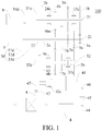
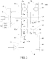
- the power-driven system 100 may include: an engine 1, a plurality of input shafts, a plurality of output shafts, a first motor generator 4, a second motor generator 6 and a motor power shaft 41.
- the power-driven system 100 may also include other mechanical components, e.g., a first clutch device 5d, a second clutch device 7, and the like.
- the engine 1 is configured to selectively engage with at least one of the plurality of input shafts. That is to say, when the engine 1 outputs power, the engine 1 can engage with the one of the plurality of input shafts to transmit power. Of course, the engine 1 can also simultaneously engage with several of the plurality of input shafts to transmit power.
- a gear-position driving gear is arranged on each input shaft
- a gear-position driven gear is arranged on each output shaft
- the gear-position driven gears correspondingly mesh with the gear-position driving gears.
- Power transmission between the input shafts and the output shafts can be realized by engagement between the gear-position driving gears and the gear-position driven gears.
- the output speeds of the output shafts can be changed by selecting gear-position driving gears and gear-position driven gears with different drive ratios.
- the first clutch device 5d is arranged between the engine 1 and the plurality of input shafts, and the first clutch device 5d can allow the engine 1 to selectively engage with at least one of the plurality of input shafts.
- the first clutch device 5d may be a double-clutch device, and has an input end 51d, a first output end 52d and a second output end 53d.
- the input end 51d can selectively engage with at least one of the first output end 52d and the second output end 53d. That is, the input end 51d may engage with the first output end 52d, or engage with the second output end 53d, or simultaneously engage with the first output end 52d and the second output end 53d.
- the plurality of input shafts include a first input shaft 21 and a second input shaft 22, the first output end 52d is connected with the first input shaft 21, and the second output end 53d is connected with the second input shaft 22.
- a first-gear driving gear 1a, a third-gear driving gear 3a, a fifth-gear driving gear 5a and a seventh-gear driving gear 7a are arranged on the first input shaft 21.
- a second-gear driving gear 2a and a fourth-sixth-gear driving gear 46a are arranged on the second input shaft 22.
- the second input shaft 22 is sleeved on the first input shaft 21, thereby effectively shortening the axial length of the power-driven system 100, and reducing the space of the vehicle 1000 occupied by the power-driven system 100.
- the fourth-sixth-gear driving gear 46a means that the gear can be used as a fourth-gear driving gear or a sixth-gear driving gear, thereby shortening the axial length of the second input shaft 22, and better reducing the size of the power-driven system 100.
- the second-gear driving gear 2a, the fourth-sixth-gear driving gear 46a, the seventh-gear driving gear 7a, the third-gear driving gear 3a, the fifth-gear driving gear 5a and the first-gear driving gear 1a are arranged in sequence.
- the plurality of gear-position driving gears By properly arranging the plurality of gear-position driving gears, the plurality of gear-position driven gears and the plurality of output shafts can be arranged reasonably, so that the power-driven system 100 is simple in structure and small in size.
- the plurality of output shafts includes: a first output shaft 31 and a second output shaft 32.
- a first-gear driven gear 1b, a second-gear driven gear 2b, a third-gear driven gear 3b and a fourth-gear driven gear 4b are freely sleeved on the first output shaft 31.
- a fifth-gear driven gear 5b, a sixth-gear driven gear 6b and a seventh-gear driven gear 7b are freely sleeved on the second output shaft 32.
- the first-gear driving gear 1a meshes with the first-gear driven gear 1b
- the second-gear driving gear 2a meshes with the second-gear driven gear 2b
- the third-gear driving gear 3a meshes with the third-gear driven gear 3b
- the fourth-sixth-gear driving gear 46a meshes with the fourth-gear driven gear 4b
- the fifth-gear driving gear 5a meshes with the fifth-gear driven gear 5b
- the fourth-sixth-gear driving gear 46a meshes with the sixth-gear driven gear 6b
- the seventh-gear driving gear 7a meshes with the seventh-gear driven gear 7b.
- a first-third-gear synchronizer 13c is arranged between the first-gear driven gear 1b and the third-gear driven gear 3b, and the first-third-gear synchronizer 13c can be used for synchronizing the first-gear driven gear 1b with the first output shaft 31, and synchronizing the third-gear driven gear 3b with the first output shaft 31.
- a second-fourth-gear synchronizer 24c is arranged between the second-gear driven gear 2b and the fourth-gear driven gear 4b, and the second-fourth-gear synchronizer 24c can be used for synchronizing the second-gear driven gear 2b with the first output shaft 31, and synchronizing the fourth-gear driven gear 4b with the first output shaft 31.
- a fifth-seventh-gear synchronizer 57c is arranged between the fifth-gear driven gear 5b and the seventh-gear driven gear 7b, and the fifth-seventh-gear synchronizer 57c can be used for synchronizing the fifth-gear driven gear 5b with the second output shaft 32, and synchronizing the seventh-gear driven gear 7b with the second output shaft 32.
- a sixth-gear synchronizer 6c is arranged on one side of the sixth-gear driven gear 6b, and the sixth-gear synchronizer 6c can be used for synchronizing the sixth-gear driven gear 6b with the second output shaft 32.
- a motor power shaft first gear 42 may be freely sleeved on the motor power shaft 41, a motor power shaft output gear 47 may be fixedly arranged on the motor power shaft 41, and the motor power shaft first gear 42 may selectively engage with the motor power shaft 41.
- a motor power shaft synchronizer 42c may also be arranged on the motor power shaft 41, and the motor power shaft synchronizer 42c is used for engaging the motor power shaft first gear 42 with the motor power shaft 41.
- the motor power shaft 41 and the plurality of output shafts link with a differential of the vehicle 1000.
- link can be understood as associated movement of a plurality of components (e.g., two). Taking the linkage of two components as an example, when one of the components moves, the other component also moves.
- the linkage of a gear and a shaft can be understood as, when the gear rotates, the shaft linked with the gear also rotates, or when the shaft rotates, the gear linked with the shaft also rotates.
- the linkage of shafts can be understood as, when one of the shafts rotates, the other shaft linked with the shaft also rotates.
- the linkage of gears can be understood as, when one of the gears rotates, the other gear linked with the gear also rotates.
- the motor power shaft first gear 42 links with one gear-position driving gear in the same direction. It should be noted that the linking in the same direction indicates that the motor power shaft first gear 42 and the one gear-position driving gear rotate in the same direction, and move correlatively.
- an intermediate idle gear 43 may be arranged between the motor power shaft first gear 42 and the one gear-position driving gear, so that the intermediate idle gear 43 can ensure that the motor power shaft first gear 42 links with the one gear-position driving gear in the same direction.
- the power of the engine 1 can be transmitted to the differential through the one gear-position driving gear, the intermediate idle gear 43, the motor power shaft first gear 42, the motor power shaft 41 and the motor power shaft output gear 47, so as to achieve the reverse operation of the vehicle 1000.
- the intermediate idle gear 43 may be a duplicate gear, and has a first gear portion meshing with the one gear-position driving gear and a second gear portion meshing with the motor power shaft first gear 42.
- the intermediate idle gear 43 is sleeved on the second output shaft 32, whereby the position of the intermediate idle gear 43 is appropriate, and the structure of the power-driven system 100 is reliable.
- the one gear-position driving gear may be the second-gear driving gear 2a, that is, the intermediate idle gear 43 meshes with the second-gear driving gear 2a and the motor power shaft first gear 42 respectively, thus realizing the power transmission between the second-gear driving gear 2a and the motor power shaft first gear 42.
- the motor power shaft synchronizer 42c shares a first shift mechanism with a gear-position synchronizer corresponding to one gear-position driven gear. This can save a shift mechanism, so that the cost of the power-driven system 100 can be reduced, and the structure of the power-driven system 100 is simple and reliable.
- the motor power shaft synchronizer 42c shares a first shift mechanism with the sixth-gear synchronizer 6c.
- a first output shaft output gear 31e is fixedly arranged on the first output shaft 31
- a second output shaft output gear 32e is fixedly arranged on the second output shaft 32
- the motor power shaft output gear 47, the first output shaft output gear 31e and the second output shaft output gear 32e mesh with a main reducer driven gear 8 of the vehicle 1000 respectively.
- the power transmitted to the first output shaft 31 and the second output shaft 32 can be transmitted to the main reducer driven gear 8 through the first output shaft output gear 31e and the second output shaft output gear 32e respectively, thereby driving corresponding wheels to rotate.
- Power transmission exists between the main reducer driven gear 8 and the differential. Specifically, the main reducer driven gear 8 transmits power to the differential to drive the wheels to rotate.
- the first motor generator 4 links with the motor power shaft 41.
- the first motor generator 4 can transmit power to the motor power shaft 41.
- the motor power shaft 41 can transmit power to the first motor generator 4 for power generation.
- drive gears may be arranged between the first motor generator 4 and the motor power shaft.
- Three drive gears are provided, respectively a first drive gear 44, a second drive gear 45 and a third drive gear 46.
- the first drive gear 44 is fixed on a motor shaft of the first motor generator 4
- the third drive gear 46 is fixedly connected to the motor power shaft 41
- the second drive gear 45 is meshed between the first drive gear 44 and the third drive gear 46.
- the second motor generator 6 and the engine 1 are located on an input side of the first clutch device 5d, and the second motor generator 6 may be located between the first clutch device 5d and the engine 1.
- the second motor generator 6 is arranged on the input side of the first clutch device 5d, so that the axial length of the power-driven system 100 can be effectively reduced, and the second motor generator 6 can be arranged rationally to improve the structural compactness of the power-driven system 100.
- the second motor generator 6 can be a motor generator having small capacity and small size, thereby meeting the miniaturization requirement of a transmission.
- the internal structure of the transmission has strict requirements on the space, and the second motor generator 6 having small size occupies a small space of the transmission, so that the second motor generator 6 is prevented from interfering with other components (e.g., the first clutch device 5d), and the transmission is reasonable and compact in structure.
- the plurality of input shafts is located on the output side of the first clutch device 5d.
- the second motor generator 6 is configured to carry out stationary power generation using at least part of the power of the engine 1 when the vehicle 1000 is parked. When the vehicle 1000 is parked, at least part of the power of the engine 1 can be directly transferred to the second motor generator 6 for power generation, or at least part of the power of the engine 1 can be indirectly transmitted to the second motor generator 6 for power generation through the input end 51d.
- input end outer teeth 54d may be arranged on the input end 51d, and the second motor generator 6 links with the input end outer teeth 54d.
- the power of the engine 1 can be transmitted to the second motor generator 6 through the input end 51d and the input end outer teeth 54d, and the second motor generator 6 can be used as a generator for stationary power generation.
- the second motor generator 6 and the input end 51d can be coaxially connected.
- the second motor generator 6 may be arranged between the input end 51d and the engine 1, such that the power of the engine 1 necessarily passes through the second motor generator 6 when being transmitted to the input end 51d, whereby the second motor generator 6 can be used as a generator for stationary power generation.
- the second clutch device 7 is arranged inside a rotor of the second motor generator 6. In this way, the axial length of the power-driven system 100 can be better shortened, so that the size of the power-driven system 100 can be reduced, and the arrangement flexibility of the power-driven system 100 on the vehicle 1000 can be improved.
- the second motor generator 6 can also be used as a starter.
- the engine 1, the second clutch device 7, and the input end 51d of the first clutch device 5d are coaxially arranged.
- the power-driven system 100 is compact in structure and small in size.
- the second motor generator 6 is located between the engine 1 and the first clutch device 5d in the axial direction, so that the axial length of the power-driven system 100 can be effectively shortened, the second motor generator 6 can be reasonably arranged, and the structural compactness of the power-driven system 100 can be improved.
- the first motor generator 4 is a main drive motor of the power-driven system 100, so the capacity and size of the first motor generator 4 are large.
- the motor power shaft 41 is provided to minimize the size of the power-driven system 100, and to avoid the interference between the first motor generator 4 and the second motor generator 6.
- the rated power of the first motor generator 4 is greater than that of the second motor generator 6.
- the second motor generator 6 can be a motor generator having small size and small rated power, so that the power-driven system 100 is simple in structure and small in size.
- the transmission path between the second motor generator 6 and the engine 1 is short, the power generation efficiency is high, and a part of the power of the engine 1 can be efficiently converted into electric energy.
- the peak power of the first motor generator 4 is also greater than that of the second motor generator 6.
- the rated power of the first motor generator 4 is two or more times that of the second motor generator 6.
- the peak power of the first motor generator 4 is two or more times that of the second motor generator 6.
- the rated power of the first motor generator 4 may be 60 kW
- the rated power of the second motor generator 6 may be 24 kW
- the peak power of the first motor generator 4 may be 120 kW
- the peak power of the second motor generator 6 may be 44 kW.
- the power of the engine 1 is transmitted to the first input shaft 21 and/or the second input shaft 22 through the first clutch device 5d, then transmitted to the first output shaft 31 or the second output shaft 32 through a corresponding gear-position gear pair, and finally transmitted to the differential to drive the wheels to rotate.
- the gear-position gear pair includes a gear-position driving gear and a gear-position driven gear corresponding to each other.
- the input end 51d of the first clutch device 5d selectively engages with at least one of the two output ends.
- Hybrid mode a combination of the pure engine mode and the pure electric mode, the power of the engine 1 and the power of the first motor generator 4 are coupled at the main reducer driven gear 8.
- Stationary power generation mode the power of the engine 1 is all transmitted to the second motor generator 6 through the input end 51d of the first clutch device 5d, and the second motor generator 6 functions as a generator for stationary power generation.
- First driving power generation mode a part of the power of the engine 1 is transmitted to the differential through the first clutch device 5d, the input shaft and the output shaft to drive the wheels to rotate, and the other part of the power of the engine 1 is transmitted to the second motor generator 6 through the input end 51d of the first clutch device 5d for power generation.
- Second driving power generation mode the power of the engine 1 is transmitted to the differential through the first clutch device 5d, the input shaft and the output shaft to drive the wheels to rotate, and the main reducer driven gear 8 can transmit a part of the power to the first motor generator 4 through the motor power shaft output gear 47 and the motor power shaft 41 for power generation.
- the vehicle 1000 includes the power-driven system 100 for a vehicle 1000 according to the above embodiments of the present disclosure.
- references such as reference terms “an embodiment”, “some embodiments”, “example”, “specific example”, or “some examples” intend to indicate that specific features, structures, materials, or characteristics described with reference to embodiments or examples are included in at least one embodiment or example of this disclosure.
- schematic descriptions of the foregoing terms do not need to aim at a same embodiment or example.
- the specific features, the structures, the materials or the characteristics that are described may be combined in a proper manner in any one or more embodiments or examples.
- persons skilled in the art can combine or group different embodiments or examples that are described in this specification and features of the different embodiments or examples.
Landscapes
- Engineering & Computer Science (AREA)
- Mechanical Engineering (AREA)
- Chemical & Material Sciences (AREA)
- Combustion & Propulsion (AREA)
- Transportation (AREA)
- General Engineering & Computer Science (AREA)
- Hybrid Electric Vehicles (AREA)
- Electric Propulsion And Braking For Vehicles (AREA)
Applications Claiming Priority (2)
| Application Number | Priority Date | Filing Date | Title |
|---|---|---|---|
| CN201610858369.5A CN107867165A (zh) | 2016-09-28 | 2016-09-28 | 用于车辆的动力驱动系统以及车辆 |
| PCT/CN2017/096040 WO2018059123A1 (fr) | 2016-09-28 | 2017-08-04 | Système d'entraînement électrique pour véhicule et véhicule |
Publications (2)
| Publication Number | Publication Date |
|---|---|
| EP3521086A1 true EP3521086A1 (fr) | 2019-08-07 |
| EP3521086A4 EP3521086A4 (fr) | 2019-10-16 |
Family
ID=61761241
Family Applications (1)
| Application Number | Title | Priority Date | Filing Date |
|---|---|---|---|
| EP17854576.0A Withdrawn EP3521086A4 (fr) | 2016-09-28 | 2017-08-04 | Système d'entraînement électrique pour véhicule et véhicule |
Country Status (5)
| Country | Link |
|---|---|
| US (1) | US11299041B2 (fr) |
| EP (1) | EP3521086A4 (fr) |
| KR (1) | KR20190040329A (fr) |
| CN (1) | CN107867165A (fr) |
| WO (1) | WO2018059123A1 (fr) |
Families Citing this family (7)
| Publication number | Priority date | Publication date | Assignee | Title |
|---|---|---|---|---|
| CN107867169A (zh) * | 2016-09-28 | 2018-04-03 | 比亚迪股份有限公司 | 用于车辆的动力驱动系统以及车辆 |
| CN109996695B (zh) * | 2016-11-30 | 2022-06-28 | 德纳有限公司 | 电动车辆和混合电动车辆的电动车轴传动装置 |
| DE102019202969A1 (de) * | 2019-03-05 | 2020-09-10 | Zf Friedrichshafen Ag | Hybrid-Getriebeanordnung für einen Kraftfahrzeugantriebsstrang sowie Verfahren zum Betreiben eines Hybrid-Antriebsstranges |
| CN112572127B (zh) * | 2019-09-30 | 2022-06-14 | 比亚迪股份有限公司 | 混合动力总成和具有其的车辆 |
| CN112744067B (zh) * | 2019-10-30 | 2022-08-05 | 比亚迪股份有限公司 | 混合动力系统以及具有其的车辆 |
| CN115675056B (zh) * | 2021-07-30 | 2025-01-14 | 比亚迪股份有限公司 | 动力系统和车辆 |
| CN114475208A (zh) * | 2021-12-20 | 2022-05-13 | 广西汽车集团有限公司 | 一种同轴式多挡位前驱混合动力系统 |
Family Cites Families (31)
| Publication number | Priority date | Publication date | Assignee | Title |
|---|---|---|---|---|
| JP2003301897A (ja) | 2002-04-12 | 2003-10-24 | Aisin Seiki Co Ltd | 変速装置 |
| JP3998016B2 (ja) * | 2004-11-12 | 2007-10-24 | トヨタ自動車株式会社 | 車両用駆動装置 |
| JP4301212B2 (ja) * | 2005-06-03 | 2009-07-22 | 日産自動車株式会社 | 車両の制御装置 |
| CN101209666A (zh) * | 2006-12-25 | 2008-07-02 | 比亚迪股份有限公司 | 混合动力输出装置 |
| DE102009059944A1 (de) * | 2009-01-19 | 2010-07-22 | Luk Lamellen Und Kupplungsbau Beteiligungs Kg | Hybridmodul für einen Antriebsstrang eines Fahrzeuges |
| CN102107604B (zh) * | 2009-12-25 | 2013-12-18 | 比亚迪股份有限公司 | 汽车混合动力驱动系统及其档位操作方法 |
| CN102114770B (zh) | 2009-12-31 | 2013-12-04 | 比亚迪股份有限公司 | 传动机构、混合动力驱动系统及该驱动系统的控制方法 |
| CN102114766B (zh) * | 2009-12-31 | 2014-03-19 | 比亚迪股份有限公司 | 一种混合动力驱动系统及其驱动方法 |
| CN102259583B (zh) * | 2010-05-31 | 2014-03-19 | 比亚迪股份有限公司 | 混合动力驱动系统及具有该系统的车辆 |
| CN102259584B (zh) * | 2010-05-31 | 2014-07-02 | 比亚迪股份有限公司 | 混合动力驱动系统及包含该驱动系统的车辆 |
| JP5213914B2 (ja) * | 2010-06-15 | 2013-06-19 | アイシン・エィ・ダブリュ株式会社 | ハイブリッド駆動装置 |
| EP2657098B1 (fr) * | 2010-12-24 | 2018-04-04 | Toyota Jidosha Kabushiki Kaisha | Appareil de commande de véhicule hybride |
| WO2012101791A1 (fr) * | 2011-01-26 | 2012-08-02 | トヨタ自動車株式会社 | Unité de commande pour véhicule hybride |
| DE112011105550B4 (de) * | 2011-08-24 | 2018-01-11 | Toyota Jidosha Kabushiki Kaisha | Fahrzeug-Fahrsteuervorrichtung |
| CN103917424B (zh) * | 2011-11-14 | 2016-08-17 | 丰田自动车株式会社 | 车辆用驱动装置的控制装置 |
| US9162667B2 (en) * | 2012-06-05 | 2015-10-20 | Hyundai Motor Company | Power transmitting apparatus for vehicle |
| JP6263889B2 (ja) * | 2013-07-23 | 2018-01-24 | トヨタ自動車株式会社 | ハイブリッド車両用駆動装置 |
| CN104648144A (zh) * | 2013-11-19 | 2015-05-27 | 贾新成 | 一种节油的suv汽车四驱 |
| CN204095490U (zh) * | 2014-07-31 | 2015-01-14 | 比亚迪股份有限公司 | 动力传动系统及具有该动力传动系统的车辆 |
| CN104608612B (zh) | 2014-09-10 | 2015-12-02 | 比亚迪股份有限公司 | 用于车辆的动力传动系统及具有它的车辆 |
| CN104608621B (zh) | 2014-09-10 | 2015-12-02 | 比亚迪股份有限公司 | 变速器、动力传动系统及车辆 |
| CN105459792B (zh) | 2014-09-10 | 2018-04-20 | 比亚迪股份有限公司 | 用于车辆的动力传动系统及具有它的车辆 |
| CN105644335B (zh) * | 2014-11-14 | 2020-02-28 | 上海汽车集团股份有限公司 | 车辆用双电机动力系统和双电机混合动力系统 |
| CN204340646U (zh) * | 2014-11-28 | 2015-05-20 | 安徽江淮汽车股份有限公司 | 一种混合动力传动装置 |
| EP3245092B1 (fr) * | 2015-01-16 | 2022-05-04 | BYD Company Limited | Système de transmission de puissance et véhicule le comprenant |
| CN104773063B (zh) | 2015-01-16 | 2015-12-02 | 比亚迪股份有限公司 | 变速器、动力传动系统和车辆 |
| CN104773062B (zh) | 2015-01-16 | 2015-12-30 | 比亚迪股份有限公司 | 动力传动系统及具有其的车辆 |
| CN104786816B (zh) | 2015-01-16 | 2016-03-30 | 比亚迪股份有限公司 | 用于车辆的动力传动系统及具有其的车辆 |
| CN104786814B (zh) | 2015-01-16 | 2016-04-13 | 比亚迪股份有限公司 | 变速器、动力传动系统和车辆 |
| CN105799668A (zh) * | 2016-03-22 | 2016-07-27 | 山东理工大学 | 一种多轴汽车能量再生制动装置 |
| CN206201955U (zh) * | 2016-06-29 | 2017-05-31 | 比亚迪股份有限公司 | 动力驱动系统和车辆 |
-
2016
- 2016-09-28 CN CN201610858369.5A patent/CN107867165A/zh active Pending
-
2017
- 2017-08-04 WO PCT/CN2017/096040 patent/WO2018059123A1/fr not_active Ceased
- 2017-08-04 US US16/335,843 patent/US11299041B2/en active Active
- 2017-08-04 EP EP17854576.0A patent/EP3521086A4/fr not_active Withdrawn
- 2017-08-04 KR KR1020197008767A patent/KR20190040329A/ko not_active Withdrawn
Also Published As
| Publication number | Publication date |
|---|---|
| US11299041B2 (en) | 2022-04-12 |
| EP3521086A4 (fr) | 2019-10-16 |
| KR20190040329A (ko) | 2019-04-17 |
| US20200023733A1 (en) | 2020-01-23 |
| WO2018059123A1 (fr) | 2018-04-05 |
| CN107867165A (zh) | 2018-04-03 |
Similar Documents
| Publication | Publication Date | Title |
|---|---|---|
| EP3521083B1 (fr) | Système moteur pour véhicule et véhicule | |
| US11273699B2 (en) | Power-driven system for vehicle and vehicle | |
| EP3521086A1 (fr) | Système d'entraînement électrique pour véhicule et véhicule | |
| RU2625689C2 (ru) | Гибридная трансмиссия для автотранспортного средства | |
| CN102348568B (zh) | 混合动力车辆用动力传递装置 | |
| US10899219B2 (en) | Power drive system and vehicle | |
| WO2018077273A1 (fr) | Train de puissance et véhicule équipé dudit train de puissance | |
| CN110370916B (zh) | 混合动力车辆、混合动力驱动系统以及变速箱 | |
| CN107867164B (zh) | 用于车辆的动力驱动系统以及车辆 | |
| US20190225074A1 (en) | Power drive system and vehicle | |
| CN107867171B (zh) | 用于车辆的动力驱动系统以及车辆 | |
| US20190168600A1 (en) | Power drive system and vehicle | |
| WO2018077264A1 (fr) | Système de transmission de puissance et véhicule doté de celui-ci | |
| CN107867172B (zh) | 用于车辆的动力驱动系统以及车辆 | |
| JP7275943B2 (ja) | ハイブリッド車両の駆動装置 | |
| CN107867167A (zh) | 用于车辆的动力驱动系统以及车辆 | |
| CN116353329A (zh) | 一种变速器结构、驱动系统和车辆 | |
| CN107867162B (zh) | 用于车辆的动力驱动系统以及车辆 | |
| CN107867166B (zh) | 用于车辆的动力驱动系统以及车辆 | |
| WO2018077274A1 (fr) | Système de transmission d'énergie et véhicule le comportant | |
| WO2018077248A1 (fr) | Groupe motopropulseur et véhicule comprenant ce dernier | |
| WO2018077270A1 (fr) | Groupe motopropulseur et véhicule le comportant | |
| WO2018077271A1 (fr) | Groupe motopropulseur et véhicule comprenant celui-ci |
Legal Events
| Date | Code | Title | Description |
|---|---|---|---|
| STAA | Information on the status of an ep patent application or granted ep patent |
Free format text: STATUS: THE INTERNATIONAL PUBLICATION HAS BEEN MADE |
|
| PUAI | Public reference made under article 153(3) epc to a published international application that has entered the european phase |
Free format text: ORIGINAL CODE: 0009012 |
|
| STAA | Information on the status of an ep patent application or granted ep patent |
Free format text: STATUS: REQUEST FOR EXAMINATION WAS MADE |
|
| 17P | Request for examination filed |
Effective date: 20190402 |
|
| AK | Designated contracting states |
Kind code of ref document: A1 Designated state(s): AL AT BE BG CH CY CZ DE DK EE ES FI FR GB GR HR HU IE IS IT LI LT LU LV MC MK MT NL NO PL PT RO RS SE SI SK SM TR |
|
| AX | Request for extension of the european patent |
Extension state: BA ME |
|
| A4 | Supplementary search report drawn up and despatched |
Effective date: 20190918 |
|
| RIC1 | Information provided on ipc code assigned before grant |
Ipc: F16H 3/00 20060101ALI20190912BHEP Ipc: B60K 6/547 20071001ALI20190912BHEP Ipc: B60K 6/36 20071001ALI20190912BHEP Ipc: B60K 6/44 20071001ALI20190912BHEP Ipc: B60K 6/54 20071001AFI20190912BHEP Ipc: F16H 3/08 20060101ALN20190912BHEP Ipc: B60K 6/442 20071001ALI20190912BHEP Ipc: F16H 3/093 20060101ALI20190912BHEP |
|
| DAV | Request for validation of the european patent (deleted) | ||
| DAX | Request for extension of the european patent (deleted) | ||
| STAA | Information on the status of an ep patent application or granted ep patent |
Free format text: STATUS: THE APPLICATION HAS BEEN WITHDRAWN |
|
| 18W | Application withdrawn |
Effective date: 20200103 |