EP3521461A1 - Récipient de réaction, et procédé de traitement de lixiviation pour matière première métallique utilisant ledit récipient de réaction - Google Patents
Récipient de réaction, et procédé de traitement de lixiviation pour matière première métallique utilisant ledit récipient de réaction Download PDFInfo
- Publication number
- EP3521461A1 EP3521461A1 EP17855672.6A EP17855672A EP3521461A1 EP 3521461 A1 EP3521461 A1 EP 3521461A1 EP 17855672 A EP17855672 A EP 17855672A EP 3521461 A1 EP3521461 A1 EP 3521461A1
- Authority
- EP
- European Patent Office
- Prior art keywords
- oxygen
- slurry
- reaction container
- leaching
- blow pipe
- Prior art date
- Legal status (The legal status is an assumption and is not a legal conclusion. Google has not performed a legal analysis and makes no representation as to the accuracy of the status listed.)
- Withdrawn
Links
Images
Classifications
-
- C—CHEMISTRY; METALLURGY
- C22—METALLURGY; FERROUS OR NON-FERROUS ALLOYS; TREATMENT OF ALLOYS OR NON-FERROUS METALS
- C22B—PRODUCTION AND REFINING OF METALS; PRETREATMENT OF RAW MATERIALS
- C22B3/00—Extraction of metal compounds from ores or concentrates by wet processes
- C22B3/02—Apparatus therefor
-
- C—CHEMISTRY; METALLURGY
- C22—METALLURGY; FERROUS OR NON-FERROUS ALLOYS; TREATMENT OF ALLOYS OR NON-FERROUS METALS
- C22B—PRODUCTION AND REFINING OF METALS; PRETREATMENT OF RAW MATERIALS
- C22B23/00—Obtaining nickel or cobalt
- C22B23/04—Obtaining nickel or cobalt by wet processes
- C22B23/0407—Leaching processes
- C22B23/0415—Leaching processes with acids or salt solutions except ammonium salts solutions
- C22B23/043—Sulfurated acids or salts thereof
-
- Y—GENERAL TAGGING OF NEW TECHNOLOGICAL DEVELOPMENTS; GENERAL TAGGING OF CROSS-SECTIONAL TECHNOLOGIES SPANNING OVER SEVERAL SECTIONS OF THE IPC; TECHNICAL SUBJECTS COVERED BY FORMER USPC CROSS-REFERENCE ART COLLECTIONS [XRACs] AND DIGESTS
- Y02—TECHNOLOGIES OR APPLICATIONS FOR MITIGATION OR ADAPTATION AGAINST CLIMATE CHANGE
- Y02P—CLIMATE CHANGE MITIGATION TECHNOLOGIES IN THE PRODUCTION OR PROCESSING OF GOODS
- Y02P10/00—Technologies related to metal processing
- Y02P10/20—Recycling
Definitions
- the present invention relates to a reaction container such as an autoclave device, and particularly to a reaction container for leaching a metal contained in a metal raw material at high temperature and high pressure using sulfuric acid and a leach treatment method for a metal raw material using the reaction container.
- HPAL high pressure acid leaching
- a hydrometallurgical process of obtaining a mixed sulfide of nickel and cobalt from a nickel oxide ore as a raw material by using an HPAL method includes, for example, a pre-treatment step of adjusting a particle size of a raw material ore to form a slurry, a leaching step of performing a leaching treatment by adding sulfuric acid to an ore slurry at high temperature and high pressure, a solid-liquid separation step of separating a leachate and a leach residue from a leach slurry, a neutralization step of subjecting the leachate to a neutralization treatment to remove impurities, a dezincification step of removing zinc in the leachate, a sulfuration step of adding a sulfurizing agent to the leachate subjected to dezincification treatment to generate a mixed sulfide of nickel and cobalt, and a detoxification step of detoxifying a post-sulfuration liquid (for example, see Patent Document 1).
- iron existing as goethite [FeO(OH)] in the ore is precipitated as hematite [Fe 2 O 3 ] by a hydrolysis reaction proceeding at a high temperature of 200°C or higher according to the following Formula (2), iron is hardly leached.
- iron in the ore is immobilized as hematite in an acid leaching treatment at high temperature and high pressure so that leaching of iron in the leachate can be suppressed.
- the acid leaching treatment is excellent as compared to a leaching treatment by a normal pressure leaching method.
- the HPAL method is an excellent technique capable of selectively leaching nickel and cobalt from ore containing a large amount of iron, but it is difficult to completely suppress leaching of iron and iron is contained on the order of several g/L in the leachate.
- Iron in the leachate exists as bivalent iron and trivalent iron, and an absolute amount and an abundance ratio thereof are controlled by an oxidation-reduction potential (ORP) in the leachate.
- ORP oxidation-reduction potential
- the ORP is increased to about 540 mV
- the existence form of iron is only trivalent iron, so that iron is immobilized as hematite while generating protons and thus iron does not almost exist.
- an amount of sulfuric acid used can be reduced by generation of protons occurring by an immobilization reaction of immobilizing iron as hematite, and an amount of a neutralizing agent can be suppressed in the subsequent steps since iron does not exist.
- the ORP is largely dependent on the composition of the ore to be subjected to the leaching treatment. For this reason, a technique capable of efficiently suppressing the leaching of iron while controlling the ORP is demanded.
- Patent Document 2 proposes a technique in which, in an autoclave device in which a metal is leached by blowing gas such as compressed air through a gas blow pipe while a slurry is stirred with a stirrer, a gas discharge port of the gas blow pipe is disposed in the vicinity of the lowermost stage stirring blade of the stirrer and at each of upper and lower places of the stirring blade. According to such a method, it is possible to prevent solid matters from adhering to the stirring blades or the like and to adjust a flow rate of gas, so that a reaction speed and a leaching rate can be improved.
- gas blow pipe disposed in the vicinity of the lowermost stage stirring blade of the stirrer and at each of upper and lower places of the stirring blade.
- the gas discharge port is positioned in the vicinity of the lowermost stage stirring blade. That is, a pipe that blows gas such as compressed air is inserted in a liquid phase of the slurry with which a compartment of the autoclave is loaded and the gas is blown directly to the liquid phase.
- the ORP can be controlled by gas such as compressed air
- the slurry containing sulfuric acid may reversely flow to the blow pipe side.
- the gas for controlling the ORP cannot be effectively supplied and the amount of sulfuric acid supplied to a leaching reaction is reduced, which causes a decrease in leaching rate.
- a method is considered in which a pipe that supplies gas such as oxygen (gas supply pipe) is connected to a supply pipe for sulfuric acid to be used in a leaching treatment (sulfuric acid supply pipe) and oxygen is supplied together with sulfuric acid into a slurry.
- gas supply pipe gas supply pipe
- sulfuric acid supply pipe oxygen supply pipe
- sulfuric acid may reversely flow to the gas supply pipe side and a state of a gas-liquid mixed phase of gas (gaseous material) and liquid is created, so that the supply of the gas may be unstable.
- the present invention is proposed in view of such circumstances, and an object thereof is to provide a method in which oxygen is effectively supplied to a slurry with which a reaction container is loaded, and thereby a leaching reaction can be effectively caused, during a leaching treatment which is performed using an acid such as sulfuric acid while blowing oxygen at high temperature and high pressure.
- the present inventor has conducted intensive studies, and as a result, has found that the above-described problems can be solved by providing an oxygen blow pipe that blows oxygen in a reaction container and positioning an oxygen outlet in the oxygen blow pipe at a gas phase portion inside the reaction container, thereby completing the present invention.
- oxygen is effectively supplied to a slurry with which a reaction container is loaded, and thereby a leaching reaction can be effectively caused, during a leaching treatment which is performed using an acid such as sulfuric acid while blowing oxygen at high temperature and high pressure.
- the present embodiment a specific embodiment of the present invention (hereinafter, referred to as “the present embodiment”) will be described in detail.
- the present invention is not limited to the following embodiment, and various modifications can be made within the range that does not change the spirit of the present invention.
- a reaction container according to the present invention is a reaction container in which a slurry of a metal raw material is loaded and a leaching treatment of leaching a metal contained in the metal raw material is performed by adding sulfuric acid at high temperature and high pressure.
- a slurry of the metal raw material an ore slurry to be used in a hydrometallurgical process of recovering valuable metals such as nickel and cobalt from a nickel oxide ore can be exemplified.
- an autoclave device to be used in the leaching treatment in the hydrometallurgical process of the nickel oxide ore the reaction container according to the present invention can be applied.
- this reaction container is provided with an oxygen blow pipe that blows oxygen to the slurry, and is characterized in that a leaching treatment can be performed while supplying a high concentration of oxygen, and an oxygen outlet in the oxygen blow pipe is disposed to be positioned at a gas phase portion in the reaction container in which the slurry is loaded.
- an oxidation-reduction potential (ORP) of the slurry can be appropriately controlled to a desired range. Furthermore, since the oxygen outlet in the oxygen blow pipe is disposed to be positioned at the gas phase portion, the slurry containing sulfuric acid can be prevented from reversely flowing to the oxygen blow pipe side, and a degradation in leaching efficiency caused by supply shortage of oxygen, or the like can be prevented.
- reaction container according to the present invention is applied to an autoclave device to be used in the leaching treatment in the hydrometallurgical process of the nickel oxide ore using the HPAL method.
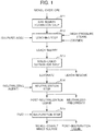
- Fig. 1 is a flowchart illustrating a flow of a hydrometallurgical process of a nickel oxide ore by an HPAL method.
- the hydrometallurgical process of the nickel oxide ore includes an ore slurry formation step S11 of forming a slurry of an nickel oxide ore as a raw material, a leaching step S12 of leaching the slurry by sulfuric acid at high temperature and high pressure to obtain a leach slurry, a solid-liquid separation step S13 of solid-liquid separating the leach slurry into a leachate and a leach residue, a neutralization step S14 of adding a neutralizing agent to the leachate to obtain a neutralized precipitate containing impurities and a post-neutralization liquid, and a sulfuration step S15 of adding a sulfurizing agent to the post-neutralization liquid to obtain a mixed sulfide of nickel and cobalt and a post-sulfuration liquid.
- the nickel oxide ore as a raw material ore is classified at a predetermined classifying point so that oversized ore particles are removed, and then water is added to undersized ore particles to obtain a coarse ore slurry.
- the nickel oxide ore as a raw material is ore containing nickel and cobalt, and a so-called laterite ore such as a limonite ore and a saprolite ore is mainly used.
- the content of nickel in the laterite ore is typically 0.8% by weight to 2.5% by weight and is contained as hydroxide or silica-magnesia (magnesium silicate) mineral.
- the content of iron is 10% by weight to 50% by weight and iron is mainly in the form of trivalent hydroxide (goethite); however, some bivalent iron is contained in silica-magnesia mineral.
- an oxide ore containing valuable metals such as nickel, cobalt, manganese, and copper, for example, manganese nodules existing at the bottom of the deep part of the sea, or the like is used.
- the method for classifying the nickel oxide ore is not particularly limited as long as it can classify ores on the basis of a desired particle diameter, and for example, the classification can be performed by sieve classification using a grizzly sieve, a grizzly sieve, or the like. Further, the classifying point is also not particularly limited, and a classifying point for obtaining an ore slurry composed of ore particles having a desired particle diameter value or less can be appropriately set.
- a leaching treatment of leaching nickel and cobalt contained in ore is performed by adding sulfuric acid to an ore slurry while supplying high-pressure steam to perform pressurization, for example, under a high temperature condition of 240°C to 260°C, using a high temperature pressurizing reaction container (such as an autoclave device).
- a leach slurry which contains a leachate containing nickel and cobalt and a leach residue containing hematite is generated.
- a metal is leached by sulfuric acid while supplying oxygen to the slurry.
- an oxygen blow pipe that supplies a high concentration of oxygen is provided in the autoclave device, and then oxygen is supplied to a gas phase portion in the autoclave device in which the ore slurry is loaded.
- ORP oxidation-reduction potential
- multistage washing is applied to the leach slurry generated in the leaching step S12 to solid-liquid separate the leach slurry into a leachate containing nickel and cobalt and a leach residue as hematite.
- the leach slurry is mixed with a washing liquid, and then a solid-liquid separation treatment is performed using a solid-liquid separation apparatus such as a thickener. Specifically, first, the slurry is diluted by a washing liquid, and then, the leach residue in the slurry is condensed as a precipitate in a thickener. According to this, the amount of nickel adhering to the leach residue can be decreased depending on the degree of the dilution. In actual operations, thickeners having such a function are multistage-connected and used.
- the pH is adjusted by adding a neutralizing agent to the leachate, thereby obtaining a neutralized precipitate containing an impurity element and a post-neutralization liquid.
- a neutralizing agent such as nickel, cobalt, and scandium are contained in the post-neutralization liquid, and the most part of impurities including aluminum becomes the neutralized precipitate.
- a neutralizing agent to be used in the neutralization treatment a known neutralizing agent can be used. Examples thereof include limestone, slaked lime, and sodium hydroxide.
- the pH is preferably adjusted to a range of 1 to 4 and more preferably to a range of 1.5 to 2.5 while preventing oxidation of the separated leachate.
- the pH is less than 1, neutralization may be insufficient, and the neutralized precipitate and the post-neutralization liquid may not be separated.
- the pH is more than 4 not only impurities including aluminum but also valuable metals such as nickel may be contained in the neutralized precipitate.
- a sulfurizing agent is added to the post-neutralization liquid obtained from the neutralization treatment in the neutralization step S14 to obtain a mixed sulfide of nickel and cobalt and a post-sulfuration liquid.
- nickel, cobalt, zinc, and the like are recovered as sulfides, and other element such as scandium remains in the post-sulfuration liquid.
- a sulfurizing agent such as hydrogen sulfide gas, sodium sulfide, or hydrogenated sodium sulfide is added to the obtained post-neutralization liquid to generate a mixed sulfide containing nickel and cobalt with less impurity components (nickel-cobalt mixed sulfide) and a post-sulfuration liquid (barren liquor) having a low and stabilized level of concentration of nickel or the like.
- a slurry containing the nickel-cobalt mixed sulfide is subjected to a separation treatment using a precipitation apparatus such as a thickener to separate and recover the mixed sulfide from the bottom of the thickener. Meanwhile, the post-sulfuration liquid as an aqueous solution component is overflowed for recovery.
- zinc in a case where zinc is contained in the post-neutralization liquid to be provided to the sulfuration treatment, before separating nickel and cobalt as sulfides, zinc can be selectively separated as a sulfide.
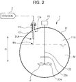
- Fig. 2 is a diagram illustrating a configuration of an autoclave device to be used in the leaching treatment in the leaching step S12 in the aforementioned hydrometallurgical process, and is a longitudinal sectional side view schematically illustrating an internal structure obtained by vertically cutting the autoclave device.
- An autoclave device 1 is a reaction container in which an ore slurry as a metal raw material is loaded and a leaching treatment of leaching a metal contained in the ore is performed by supply of sulfuric acid at high temperature and high pressure.
- This autoclave device 1 includes a main body portion 11 that has an ore slurry M loaded therein and is a leaching reaction field, and a stirrer 12 that stirs the ore slurry.
- an oxygen blow pipe 13 that blows oxygen to the ore slurry is provided in the autoclave device 1.
- the main body portion 11 has the ore slurry M loaded therein and is a reaction field in which the leaching reaction by sulfuric acid occurs.
- the main body portion 11 is, although not illustrated in the drawing, for example, partitioned in a plurality of compartments by partition walls, the leaching reaction occurs in each compartment, and the slurry is overflowed and transferred from the upstream compartment to the downstream compartment.
- various supply pipes such as a sulfuric acid supply pipe that supplies a sulfuric acid solution to be used in the leaching treatment while drooping from the upper portion of the main body portion, a slurry inlet pipe for loading an ore slurry to be treated in the compartment on the uppermost stream, and a steam supply pipe for supplying high-pressure steam or the like, are attached.
- a sulfuric acid supply pipe that supplies a sulfuric acid solution to be used in the leaching treatment while drooping from the upper portion of the main body portion
- a slurry inlet pipe for loading an ore slurry to be treated in the compartment on the uppermost stream
- a steam supply pipe for supplying high-pressure steam or the like
- the wall surface inside the main body portion is preferably made of a material containing titanium (Ti). Since the leaching reaction by sulfuric acid occurs at high temperature and high pressure as described above in the main body portion 11, the wall surface is preferably made of a material having corrosion resistance, and particularly, by the wall surface being made of Ti, corrosion resistance thereof can be enhanced.
- the stirrer 12 is disposed inside the main body portion 11, and for example, in a case where the inside of the main body portion 11 is partitioned in a plurality of compartments by partition walls, the stirrer 12 is disposed in each of the compartments.
- the stirrer 12 stirs the slurry loaded inside the main body portion 11.
- stirrer 12 for example, as schematically illustrated in Fig. 2 , it is possible to use a propeller-shaped stirrer provided with a stirring shaft 22 connected to a motor 21 and stirring blades 23 disposed at end portions of the stirring shaft.
- the stirrer 12 droops from the ceiling above the main body portion 11, and the stirring shaft 22 can be provided to be positioned at the center portion in the reaction space when the autoclave device 1 is viewed from the upper portion.
- the stirrer 12 rotates the stirring shaft 22 at a predetermined speed, for example, clockwise by driving of the motor 21 and stirs the slurry by the stirring blades 23.
- the stirring blades 23 (23a and 23b) can be provided in plural in the vertical direction in the end portions of the stirring shaft 22.
- the oxygen blow pipe 13 is a pipe for blowing and supplying a high concentration of oxygen to the ore slurry.
- the oxygen blow pipe 13 is, for example, provided to droop from the ceiling above the main body portion 11.
- the oxygen blow pipe 13 is provided to be fixed to a flange 14 provided at the upper portion of the main body portion 11.
- This oxygen blow pipe 13 is connected to an oxygen generating facility 2, and oxygen generated in the oxygen generating facility 2 is supplied into the main body portion 11 through the oxygen blow pipe 13.
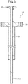
- Fig. 3 is a cross-sectional view illustrating an example of a configuration of the oxygen blow pipe 13.
- the oxygen blow pipe 13 is, for example, a nozzle-shaped pipe and is provided with a pipe portion 31, an attaching flange 32 that attaches and fixes the oxygen blow pipe 13 to the flange 14 at the upper portion of the main body portion 11, and a connecting flange 33 for connecting the oxygen blow pipe 13 to the oxygen generating facility 2.
- the attaching flange 32 and the connecting flange 33 are connected to counterpart flanges (the flange 14 at the upper portion of the main body portion 11 and a flange (not illustrated) provided in the oxygen generating facility 2) by bolt fastening, welding, or the like.
- an oxygen outlet 31A exists at the distal end of the pipe portion 31 (end portion opposite to a connection portion with the oxygen generating facility 2), and oxygen is discharged from the oxygen outlet 31A.
- the oxygen blow pipe 13 is disposed such that the oxygen outlet 31A is positioned at a gas phase portion (space indicated by symbol "11G" in Fig. 2 ) in the main body portion 11 in which the slurry is loaded. That is, the oxygen outlet 31A is disposed in a state of not coming in contact with the liquid level of the slurry, and oxygen is blown from the oxygen outlet 31A positioned at the gas phase portion 11G toward the liquid level of the slurry in the main body portion 11.
- the oxygen outlet 31A of the oxygen blow pipe 13 is positioned at the gas phase portion 11G in the main body portion 11, so that oxygen is blown to the gas phase portion 11G and then oxygen blown to the gas phase portion 11G is gradually incorporated in the slurry so as to be dissolved. Therefore, for example, by controlling the amount of oxygen supplied through the oxygen blow pipe 13, the ORP of the slurry can be appropriately controlled in a desired range.
- the oxygen outlet 31A of the oxygen blow pipe 13 is provided to be positioned at the gas phase portion 11G, unlike a related art in which the oxygen outlet in the oxygen blow pipe is inserted in a liquid phase and oxygen is blown directly to the liquid phase (for example, the technique described in Patent Document 2), a problem does not arise in that the slurry containing sulfuric acid or the like reversely flows in the pipe, so that a decrease in leaching rate of nickel and cobalt can be suppressed.
- the autoclave device 1 since the leaching treatment is performed using sulfuric acid, for example, at a high temperature of 245°C or higher while oxygen is blown through the oxygen blow pipe 13, a possibility that corrosion occurs inside the autoclave device 1 is considered. For this reason, as for such an autoclave device 1 performing the leaching treatment, as described above, from the viewpoint of enhancing corrosion resistance, the autoclave device is preferably made of a material containing Ti.
- the oxygen outlet 31A of the oxygen blow pipe 13 is preferably disposed to be separated from the wall surface inside the main body portion 11 of the autoclave device 1.
- the oxygen outlet 31A is preferably disposed at a substantially intermediate point between a wall surface 11s in the main body portion 11 and a liquid level Ms of the slurry as a position in a height direction (arrow H direction in Fig. 2 ) of the autoclave device 1.
- the gas phase portion 11G in the main body portion 11 of the autoclave device 1 is made of a mixed gas of steam and an inert gas of over pressure content (such as N 2 , O 2 , or generated CO 2 ), but the most part thereof is steam and the average molecular weight is estimated to be about 20.
- oxygen to be supplied through the oxygen blow pipe 13 has a large specific gravity and is cold, when oxygen is supplied to the gas phase portion 11G inside the main body portion 11 toward the liquid level of the slurry, oxygen flows in the liquid level direction directly. Therefore, oxygen to be supplied is not brought into direct contact with the wall surface inside the autoclave device 1, that is, the wall surface made of Ti.
- Ni-Cr-Mo nickel-chromium-molybdenum
- the Ni-Cr-Mo alloy optionally includes manganese, silicon, cobalt, tungsten, tantalum, iron, and the like, and examples thereof include 58Ni-22Cr-13Mo-3W-3Fe (commercially available product: HASTELLOY C-22), 60Ni-19Cr-19Mo-2Ta (commercially available product: MAT21), and 53Ni-45Cr-1Mo (commercially available product: MC Alloy).
- the leaching treatment by sulfuric acid was performed using the autoclave device 1 as illustrated in Fig. 2 .
- an autoclave device provided with the main body portion 11, the stirrer 12, and the oxygen blow pipe 13 was used.
- the inner wall of the main body portion 11 of the autoclave device 1 was made of Ti.
- the flange 14 was provided at the upper side of the outer portion thereof and then the oxygen blow pipe 13 was fixed and attached to the flange 14.
- An ore slurry was loaded in the main body portion 11 of such an autoclave device 1 such that the height of liquid level of the slurry became 4200 mm.
- the oxygen outlet 31A positioned at the distal end portion thereof was provided to be disposed at a height position of 290 mm from the upper wall surface of the main body portion 11. At this time, the distance between the liquid level of the slurry and the oxygen outlet 31A was 170 mm, and thus the oxygen outlet 31A was allowed to blow oxygen to the gas phase portion 11G in the main body portion 11.
- an oxygen blow pipe having the shape and configuration as illustrated in Fig. 3 was used and was made of a nickel base alloy. Further, the length of the pipe portion 31 of the oxygen blow pipe 13 was set to 1170 mm.
- the leaching treatment by sulfuric acid was performed using such an autoclave device 1 while supplying oxygen toward the liquid level of the slurry. Incidentally, conditions at the time of the leaching treatment are described below.
Landscapes
- Chemical & Material Sciences (AREA)
- Engineering & Computer Science (AREA)
- Organic Chemistry (AREA)
- Materials Engineering (AREA)
- Mechanical Engineering (AREA)
- Metallurgy (AREA)
- Manufacturing & Machinery (AREA)
- Life Sciences & Earth Sciences (AREA)
- Environmental & Geological Engineering (AREA)
- General Life Sciences & Earth Sciences (AREA)
- Geochemistry & Mineralogy (AREA)
- Geology (AREA)
- Manufacture And Refinement Of Metals (AREA)
Applications Claiming Priority (2)
| Application Number | Priority Date | Filing Date | Title |
|---|---|---|---|
| JP2016191952A JP6409843B2 (ja) | 2016-09-29 | 2016-09-29 | 反応容器、及びその反応容器を用いた金属原料の浸出処理方法 |
| PCT/JP2017/032532 WO2018061714A1 (fr) | 2016-09-29 | 2017-09-08 | Récipient de réaction, et procédé de traitement de lixiviation pour matière première métallique utilisant ledit récipient de réaction |
Publications (2)
| Publication Number | Publication Date |
|---|---|
| EP3521461A1 true EP3521461A1 (fr) | 2019-08-07 |
| EP3521461A4 EP3521461A4 (fr) | 2020-05-13 |
Family
ID=61759535
Family Applications (1)
| Application Number | Title | Priority Date | Filing Date |
|---|---|---|---|
| EP17855672.6A Withdrawn EP3521461A4 (fr) | 2016-09-29 | 2017-09-08 | Récipient de réaction, et procédé de traitement de lixiviation pour matière première métallique utilisant ledit récipient de réaction |
Country Status (5)
| Country | Link |
|---|---|
| EP (1) | EP3521461A4 (fr) |
| JP (1) | JP6409843B2 (fr) |
| AU (1) | AU2017335250B2 (fr) |
| PH (1) | PH12019500223B1 (fr) |
| WO (1) | WO2018061714A1 (fr) |
Families Citing this family (2)
| Publication number | Priority date | Publication date | Assignee | Title |
|---|---|---|---|---|
| CN113088688A (zh) * | 2021-04-15 | 2021-07-09 | 攀钢集团攀枝花钢铁研究院有限公司 | 一种适用于钒渣浸出工序的加酸装置 |
| CN117604242B (zh) * | 2023-11-13 | 2024-09-27 | 湖南三立集团股份有限公司 | 一种电解锌用浸出装置及其使用方法 |
Family Cites Families (8)
| Publication number | Priority date | Publication date | Assignee | Title |
|---|---|---|---|---|
| JPS52153801A (en) * | 1976-06-18 | 1977-12-21 | Toho Zinc Co Ltd | Method for treatment of speiss produced in lead ore smelting |
| JPH1149502A (ja) * | 1997-08-01 | 1999-02-23 | Toyota Central Res & Dev Lab Inc | 酸化物粉末の製造方法 |
| US6368381B1 (en) * | 1998-03-11 | 2002-04-09 | Placer Dome Technical Services, Ltd. | Autoclave using agitator and sparge tube to provide high oxygen transfer rate to metal-containing solutions |
| JP4365124B2 (ja) * | 2003-03-27 | 2009-11-18 | Dowaホールディングス株式会社 | 亜鉛精鉱の浸出処理法 |
| JP2005185886A (ja) * | 2003-12-24 | 2005-07-14 | Mitsubishi Heavy Ind Ltd | 嫌気性消化槽設備および嫌気性消化槽設備の制御方法 |
| JP2011033268A (ja) * | 2009-07-31 | 2011-02-17 | Tdk Corp | 噴霧乾燥装置および顆粒の製造方法 |
| JP5790726B2 (ja) * | 2013-03-19 | 2015-10-07 | 住友金属鉱山株式会社 | ニッケル酸化鉱石の湿式製錬方法 |
| JP6135609B2 (ja) * | 2014-06-30 | 2017-05-31 | 住友金属鉱山株式会社 | オートクレーブへのガス吹込み方法 |
-
2016
- 2016-09-29 JP JP2016191952A patent/JP6409843B2/ja active Active
-
2017
- 2017-09-08 WO PCT/JP2017/032532 patent/WO2018061714A1/fr not_active Ceased
- 2017-09-08 AU AU2017335250A patent/AU2017335250B2/en active Active
- 2017-09-08 EP EP17855672.6A patent/EP3521461A4/fr not_active Withdrawn
-
2019
- 2019-01-31 PH PH12019500223A patent/PH12019500223B1/en unknown
Also Published As
| Publication number | Publication date |
|---|---|
| AU2017335250A1 (en) | 2019-01-24 |
| WO2018061714A1 (fr) | 2018-04-05 |
| AU2017335250B2 (en) | 2019-11-21 |
| JP6409843B2 (ja) | 2018-10-24 |
| JP2018053321A (ja) | 2018-04-05 |
| PH12019500223A1 (en) | 2019-10-28 |
| PH12019500223B1 (en) | 2019-10-28 |
| EP3521461A4 (fr) | 2020-05-13 |
Similar Documents
| Publication | Publication Date | Title |
|---|---|---|
| AU2007288123B2 (en) | Improved hydrometallurgical method for the extraction of nickel from laterite ores | |
| EP2990495A1 (fr) | Procédé d'hydrométallurgie pour minerai d'oxyde de nickel | |
| AU2011255953B2 (en) | Method for controlling reaction in sulfuration reaction step | |
| CN1330780C (zh) | 含镍和钴的材料的还原性含氨浸取 | |
| EP3279344B1 (fr) | Procédé de fabrication d'un sulfure mixte de nickel et de cobalt et procédé hydrométallurgique pour minerai d'oxyde de nickel | |
| EP3670687A1 (fr) | Procédé de traitement de lixiviation, et procédé de fusion humide de minerai d'oxyde de nickel | |
| JP6388043B2 (ja) | 硫化物の製造方法、ニッケル酸化鉱石の湿式製錬方法 | |
| AU2017349141B2 (en) | Hydrometallurgical method for nickel oxide ore | |
| JP2017061733A (ja) | ニッケル酸化鉱石の湿式製錬方法、浸出処理設備 | |
| AU2017335250B2 (en) | Reaction container, and leach treatment method for metal raw material using said reaction container | |
| AU2017335251B2 (en) | Oxygen blow pipe, and leaching treatment method for metal material | |
| US20180044760A1 (en) | Method for producing nickel sulfide and hydrometallurgical method for nickel oxide ore | |
| JPWO2019172392A1 (ja) | Ni・Co硫化物製造方法及び鉄品位安定化システム | |
| JP2020028858A (ja) | ニッケル酸化鉱石の湿式製錬プロセスにおける最終中和方法 | |
| AU2011219678B2 (en) | Method for enhancing solid-liquid separation in conjunction with laterite leaching | |
| JP7293873B2 (ja) | ニッケル硫化物の製造方法、ニッケル酸化鉱石の湿式製錬方法 | |
| AU2007100902A4 (en) | Improved Hydrometallurgical Method for the Extraction of Nickel from Laterite Ores | |
| JP2024018929A (ja) | ニッケル酸化鉱石の湿式製錬方法 |
Legal Events
| Date | Code | Title | Description |
|---|---|---|---|
| STAA | Information on the status of an ep patent application or granted ep patent |
Free format text: STATUS: THE INTERNATIONAL PUBLICATION HAS BEEN MADE |
|
| PUAI | Public reference made under article 153(3) epc to a published international application that has entered the european phase |
Free format text: ORIGINAL CODE: 0009012 |
|
| STAA | Information on the status of an ep patent application or granted ep patent |
Free format text: STATUS: REQUEST FOR EXAMINATION WAS MADE |
|
| 17P | Request for examination filed |
Effective date: 20190410 |
|
| AK | Designated contracting states |
Kind code of ref document: A1 Designated state(s): AL AT BE BG CH CY CZ DE DK EE ES FI FR GB GR HR HU IE IS IT LI LT LU LV MC MK MT NL NO PL PT RO RS SE SI SK SM TR |
|
| AX | Request for extension of the european patent |
Extension state: BA ME |
|
| DAV | Request for validation of the european patent (deleted) | ||
| DAX | Request for extension of the european patent (deleted) | ||
| A4 | Supplementary search report drawn up and despatched |
Effective date: 20200415 |
|
| RIC1 | Information provided on ipc code assigned before grant |
Ipc: C22B 3/02 20060101ALI20200407BHEP Ipc: C22B 3/00 20060101ALI20200407BHEP Ipc: C22B 23/00 20060101AFI20200407BHEP |
|
| STAA | Information on the status of an ep patent application or granted ep patent |
Free format text: STATUS: EXAMINATION IS IN PROGRESS |
|
| 17Q | First examination report despatched |
Effective date: 20210119 |
|
| STAA | Information on the status of an ep patent application or granted ep patent |
Free format text: STATUS: THE APPLICATION HAS BEEN WITHDRAWN |
|
| 18W | Application withdrawn |
Effective date: 20210510 |