EP3521841B1 - Procédé de déclenchement d'un relais de protection de distance surveillant une zone - Google Patents
Procédé de déclenchement d'un relais de protection de distance surveillant une zone Download PDFInfo
- Publication number
- EP3521841B1 EP3521841B1 EP19151252.4A EP19151252A EP3521841B1 EP 3521841 B1 EP3521841 B1 EP 3521841B1 EP 19151252 A EP19151252 A EP 19151252A EP 3521841 B1 EP3521841 B1 EP 3521841B1
- Authority
- EP
- European Patent Office
- Prior art keywords
- impedance value
- change
- time step
- line impedance
- zone
- Prior art date
- Legal status (The legal status is an assumption and is not a legal conclusion. Google has not performed a legal analysis and makes no representation as to the accuracy of the status listed.)
- Active
Links
Images
Classifications
-
- H—ELECTRICITY
- H02—GENERATION; CONVERSION OR DISTRIBUTION OF ELECTRIC POWER
- H02H—EMERGENCY PROTECTIVE CIRCUIT ARRANGEMENTS
- H02H3/00—Emergency protective circuit arrangements for automatic disconnection directly responsive to an undesired change from normal electric working condition with or without subsequent reconnection ; integrated protection
- H02H3/44—Emergency protective circuit arrangements for automatic disconnection directly responsive to an undesired change from normal electric working condition with or without subsequent reconnection ; integrated protection responsive to the rate of change of electrical quantities
-
- H—ELECTRICITY
- H02—GENERATION; CONVERSION OR DISTRIBUTION OF ELECTRIC POWER
- H02H—EMERGENCY PROTECTIVE CIRCUIT ARRANGEMENTS
- H02H3/00—Emergency protective circuit arrangements for automatic disconnection directly responsive to an undesired change from normal electric working condition with or without subsequent reconnection ; integrated protection
- H02H3/40—Emergency protective circuit arrangements for automatic disconnection directly responsive to an undesired change from normal electric working condition with or without subsequent reconnection ; integrated protection responsive to ratio of voltage and current
-
- G—PHYSICS
- G01—MEASURING; TESTING
- G01R—MEASURING ELECTRIC VARIABLES; MEASURING MAGNETIC VARIABLES
- G01R19/00—Arrangements for measuring currents or voltages or for indicating presence or sign thereof
- G01R19/25—Arrangements for measuring currents or voltages or for indicating presence or sign thereof using digital measurement techniques
- G01R19/2513—Arrangements for monitoring electric power systems, e.g. power lines or loads; Logging
-
- G—PHYSICS
- G01—MEASURING; TESTING
- G01R—MEASURING ELECTRIC VARIABLES; MEASURING MAGNETIC VARIABLES
- G01R31/00—Arrangements for testing electric properties; Arrangements for locating electric faults; Arrangements for electrical testing characterised by what is being tested not provided for elsewhere
- G01R31/08—Locating faults in cables, transmission lines, or networks
- G01R31/081—Locating faults in cables, transmission lines, or networks according to type of conductors
- G01R31/085—Locating faults in cables, transmission lines, or networks according to type of conductors in power transmission or distribution lines, e.g. overhead
-
- H—ELECTRICITY
- H02—GENERATION; CONVERSION OR DISTRIBUTION OF ELECTRIC POWER
- H02H—EMERGENCY PROTECTIVE CIRCUIT ARRANGEMENTS
- H02H1/00—Details of emergency protective circuit arrangements
- H02H1/0007—Details of emergency protective circuit arrangements concerning the detecting means
-
- H—ELECTRICITY
- H02—GENERATION; CONVERSION OR DISTRIBUTION OF ELECTRIC POWER
- H02H—EMERGENCY PROTECTIVE CIRCUIT ARRANGEMENTS
- H02H3/00—Emergency protective circuit arrangements for automatic disconnection directly responsive to an undesired change from normal electric working condition with or without subsequent reconnection ; integrated protection
- H02H3/38—Emergency protective circuit arrangements for automatic disconnection directly responsive to an undesired change from normal electric working condition with or without subsequent reconnection ; integrated protection responsive to both voltage and current; responsive to phase angle between voltage and current
-
- H—ELECTRICITY
- H02—GENERATION; CONVERSION OR DISTRIBUTION OF ELECTRIC POWER
- H02H—EMERGENCY PROTECTIVE CIRCUIT ARRANGEMENTS
- H02H7/00—Emergency protective circuit arrangements specially adapted for specific types of electric machines or apparatus or for sectionalised protection of cable or line systems, and effecting automatic switching in the event of an undesired change from normal working conditions
- H02H7/04—Emergency protective circuit arrangements specially adapted for specific types of electric machines or apparatus or for sectionalised protection of cable or line systems, and effecting automatic switching in the event of an undesired change from normal working conditions for transformers
- H02H7/05—Emergency protective circuit arrangements specially adapted for specific types of electric machines or apparatus or for sectionalised protection of cable or line systems, and effecting automatic switching in the event of an undesired change from normal working conditions for transformers for capacitive voltage transformers, e.g. against resonant conditions
-
- H—ELECTRICITY
- H02—GENERATION; CONVERSION OR DISTRIBUTION OF ELECTRIC POWER
- H02H—EMERGENCY PROTECTIVE CIRCUIT ARRANGEMENTS
- H02H7/00—Emergency protective circuit arrangements specially adapted for specific types of electric machines or apparatus or for sectionalised protection of cable or line systems, and effecting automatic switching in the event of an undesired change from normal working conditions
- H02H7/26—Sectionalised protection of cable or line systems, e.g. for disconnecting a section on which a short-circuit, earth fault, or arc discharge has occured
-
- G—PHYSICS
- G01—MEASURING; TESTING
- G01R—MEASURING ELECTRIC VARIABLES; MEASURING MAGNETIC VARIABLES
- G01R27/00—Arrangements for measuring resistance, reactance, impedance, or electric characteristics derived therefrom
- G01R27/02—Measuring real or complex resistance, reactance, impedance, or other two-pole characteristics derived therefrom, e.g. time constant
- G01R27/16—Measuring impedance of element or network through which a current is passing from another source, e.g. cable, power line
-
- H—ELECTRICITY
- H02—GENERATION; CONVERSION OR DISTRIBUTION OF ELECTRIC POWER
- H02H—EMERGENCY PROTECTIVE CIRCUIT ARRANGEMENTS
- H02H1/00—Details of emergency protective circuit arrangements
- H02H1/04—Arrangements for preventing response to transient abnormal conditions, e.g. to lightning or to short duration over voltage or oscillations; Damping the influence of DC component by short circuits in AC networks
-
- H—ELECTRICITY
- H02—GENERATION; CONVERSION OR DISTRIBUTION OF ELECTRIC POWER
- H02H—EMERGENCY PROTECTIVE CIRCUIT ARRANGEMENTS
- H02H3/00—Emergency protective circuit arrangements for automatic disconnection directly responsive to an undesired change from normal electric working condition with or without subsequent reconnection ; integrated protection
- H02H3/02—Details
- H02H3/05—Details with means for increasing reliability, e.g. redundancy arrangements
Definitions
- the invention relates to a method for triggering a distance protection relay monitoring a zone, in which a line impedance value is determined in each case in predetermined time steps.
- Distance protection relays are used in power supply networks to enable selective shutdown of an affected line section in the event of a fault.
- the line impedance In order to be able to determine the fault location as precisely as possible, the line impedance must be determined exactly by measuring the current and voltage ( WO 2010048972 A1 ).
- the voltage measurement is often carried out using inductive voltage converters, as these can follow the voltage curve on the top side very well and thus have good transmission behavior. As the voltage increases, however, inductive voltage converters are increasingly uneconomical to use due to the associated increase in size.
- CVT - Capacitive Voltage Transformers are preferably used for voltage measurement in voltage ranges above 100 kV, but they have the serious disadvantage that in the event of a fault they are subject to strong transient transition effects and therefore impair the determination of the fault location. CVTs therefore have a significantly worse transmission behavior than inductive voltage converters.
- distance protection arrangements for monitoring an electrical power transmission line are known from the prior art, with at least two distance protection relays exchanging data with one another, in particular in order to be able to automatically set the zones ( WO 2009095040 A1 ).
- delta values represent changes that the current and voltage experience during the transition from the normal to the faulty state.
- the delta values are evaluated on the complex level and a change in the line impedance is determined once per fault event. The zone decision is then controlled via the line impedance change.
- the invention is therefore based on the object of creating a method which, despite the use of a voltage converter with an unfavorable transmission behavior, enables the location of the fault to be reliably determined before transient transition effects have subsided.
- the invention solves the problem in that the change amount of a change vector between the line impedance value determined for the respective time step and the respective preceding time step as well as a change amount limit value determined from the line impedance value determined for the respective time step and a zone limit impedance value is assigned to each time step and, if a predetermined number of change amounts assigned to each time step is below the change amount limit value assigned to the respective time step, the line impedance value of the last time step is output to generate a trigger signal as a function of the zone limit impedance value.
- the method according to the invention is based on the knowledge that the amounts of change in the change vectors decrease over time during the decay of the transient transition effects after the occurrence of most line faults, which enables the progress of the transient transition effects to be estimated without the need for a mathematical model of the transmission behavior of the voltage converter is needed.
- the line impedance value is determined in predetermined time steps in a manner known to a person skilled in the art, in which the instantaneous values of current and voltage are usually measured and the complex line impedance value is determined therefrom. For each time step, the amount of change is then determined as the vector amount of the vector of change between the respective and the respective preceding complex line impedance value.
- a change amount limit value is determined for each time step, taking into account the zone limit impedance value specified for the respective distance protection relay and the line impedance value determined for the respective time step.
- the ratio of these two values to one another allows a conclusion to be drawn as to how close a possible line fault is to the border of the monitored zone.
- the change amount limit value is therefore determined in such a way that it decreases the closer a possible line fault is to the border of the monitored zone, and that it increases the further a possible line fault is away from the border of the monitored zone and is therefore clearly within the zone.
- the trigger signal itself can also be derived in a manner known to the person skilled in the art from the ratio between the line impedance value and the zone limit impedance value.
- the trigger signal be determined only on the basis of the reactance, that is to say the imaginary component of the line impedance value and the zone limit impedance value.
- the change amount limit value for a time step decrease as the distance between the line impedance value and the zone limit impedance value becomes smaller.
- the line impedance value for the trigger signal is only used for line faults close to the zone boundary when the transient transition effects have already subsided significantly.
- Particularly favorable trigger conditions arise in this context when the change amount limit value is a predetermined minimum at a ratio between reaches the line impedance value and the zone limit impedance value by 1 and increases linearly from this minimum value with increasing or decreasing ratio up to a predetermined maximum value.
- a distance protection relay for carrying out the method according to the invention can be configured with particularly few parameters.
- the proposed method is suitable for many types of line faults, arcs lead to change amounts that are not or only at a very late point in time consecutively below the change amount limit values determined.
- the rate of change of the angle of the change vector be assigned to each time step and that a trigger signal be output if the rate of change exceeds a predetermined rate of change in the arc angle. Since the rate of change of the angle of the change vector in arcs typically follows the random principle and can thus be distinguished from conventional line faults, in which the angle of the change vector remains essentially constant, an arc can be reliably detected and the affected line section can be switched off immediately.
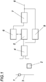
- a distance protection relay for carrying out the method according to the invention comprises a current converter 1 and a voltage converter 2 for measurement of instantaneous current and voltage values of a power line 3. From the measured current and voltage values, a line impedance value is determined at predetermined time steps using an impedance measuring device 4. The individual line impedance values are transferred to a stability monitor 5, which stores the respective line impedance value in a memory 6 in order to first form the amount of change of the change vector between the line impedance value determined for the respective time step and the respective preceding time step and to also store this in the memory 6.
- a change amount limit value determined from the line impedance value for the respective time step and a specified zone limit impedance value is determined in the stability monitor 5 for each time step, which is also stored in the memory 6 and assigned to the associated change amount that was determined at the same time step.
- the memory 6 is queried by a trigger unit 7, which checks for a predetermined number of change amounts in the memory 6 whether these are below the associated change amount limit values, which are also stored in the memory 6. If this is the case, the tripping unit 7 determines the estimated location of the line fault on the basis of the last line impedance value, which is transferred for this purpose by the stability monitor 5 and the specified zone limit impedance value, and outputs a trip signal 8 for the assigned circuit breaker if the line fault is within the monitored line Zone lies.
- the distance protection relay can have a monitoring unit 9 which determines the rate of change of the angle of the change vector at each time step and outputs a trigger signal 8 ahead of time if the rate of change exceeds a predetermined rate of change in the arc angle.
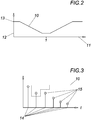
- the relationship between the change amount limit value 10 and the ratio 11 between the line impedance value and the zone limit impedance value is shown schematically.
- the change amount limit increases 10 from a minimum value 12 at a ratio of 11 by 1 on both sides linearly up to a maximum value 13.
- the change amount limit value 10 changes in several successive time steps 14 if the ratio 11 between the line impedance value and the zone limit impedance value also changes, as is the case, for example, in FIG Fig. 3 is shown. Only when a predetermined number of change amounts 15 is below the respective change amount limit value 10 is a release signal 8 output via the release unit 7.
Landscapes
- Engineering & Computer Science (AREA)
- Power Engineering (AREA)
- Physics & Mathematics (AREA)
- General Physics & Mathematics (AREA)
- Emergency Protection Circuit Devices (AREA)
Claims (3)
- Procédé pour déclencher un relais de protection de distance surveillant une zone par lequel une valeur d'impédance de ligne est déterminée à incréments temporels prédéfinis, dans lequel à chaque incrément temporel est associé le montant de variation du vecteur de variation entre la valeur d'impédance de ligne déterminée à l'incrément temporel concerné et celle déterminée à l'incrément temporel précédent ainsi qu'une valeur limite de montant de variation (10) déterminée à partir de la valeur d'impédance de ligne déterminée à l'incrément temporel concerné et d'une valeur d'impédance de limite de zone et, quand un nombre prédéfini de montants de variation associés à un incrément temporel sont inférieurs à la valeur limite de montant de variation (10) associée à l'incrément temporel concerné, la valeur d'impédance de ligne du dernier incrément temporel est émise pour générer un signal de déclenchement (8) en fonction de la valeur d'impédance de limite de zone.
- Procédé selon la revendication 1, caractérisé en ce que la valeur limite de montant de variation (10) diminue pour un incrément temporel présentant un écart en baisse entre la valeur d'impédance de ligne et la valeur d'impédance de limite de zone.
- Procédé selon une des revendications 1 et 2, caractérisé en ce qu'à chaque incrément temporel est associé le taux de variation de l'angle du vecteur de variation et que, quand le taux de variation dépasse un taux de variation d'angle d'arc électrique prédéfini, un signal de déclenchement (8) est émis.
Applications Claiming Priority (1)
| Application Number | Priority Date | Filing Date | Title |
|---|---|---|---|
| ATA50013/2018A AT520806B1 (de) | 2018-01-11 | 2018-01-11 | Verfahren zum Auslösen eines eine Zone überwachenden Distanzschutzrelais |
Publications (2)
| Publication Number | Publication Date |
|---|---|
| EP3521841A1 EP3521841A1 (fr) | 2019-08-07 |
| EP3521841B1 true EP3521841B1 (fr) | 2021-06-02 |
Family
ID=65013614
Family Applications (1)
| Application Number | Title | Priority Date | Filing Date |
|---|---|---|---|
| EP19151252.4A Active EP3521841B1 (fr) | 2018-01-11 | 2019-01-10 | Procédé de déclenchement d'un relais de protection de distance surveillant une zone |
Country Status (2)
| Country | Link |
|---|---|
| EP (1) | EP3521841B1 (fr) |
| AT (1) | AT520806B1 (fr) |
Families Citing this family (2)
| Publication number | Priority date | Publication date | Assignee | Title |
|---|---|---|---|---|
| CN111525523B (zh) * | 2020-05-13 | 2021-10-01 | 中国大唐集团科学技术研究院有限公司华东电力试验研究院 | 基于大数据的新能源电站继电保护定值校核方法及系统 |
| CN120566378B (zh) * | 2025-07-25 | 2026-01-02 | 广州豫能科技有限公司 | 一种大距离间隔环距离保护防误跳闸的方法及装置 |
Family Cites Families (7)
| Publication number | Priority date | Publication date | Assignee | Title |
|---|---|---|---|---|
| DE2237854C3 (de) * | 1972-08-01 | 1980-09-04 | Siemens Ag, 1000 Berlin Und 8000 Muenchen | Distanzschutzrelais mit einer polygonalen Auslösecharakteristik |
| DE19920654A1 (de) * | 1999-05-05 | 2000-11-09 | Abb Research Ltd | Verfahren zur Bestimmung eines Leitungsimpedanz-Grenzwertes in einem Distanzschutzgerät |
| US7457088B2 (en) * | 2004-09-29 | 2008-11-25 | Schweitzer Engineering Laboratories, Inc. | Systems and methods for protection of electrical networks |
| JP4874824B2 (ja) * | 2007-01-30 | 2012-02-15 | 三菱電機株式会社 | 距離継電装置 |
| EP2238664B1 (fr) * | 2008-01-31 | 2017-03-22 | Siemens Aktiengesellschaft | Systeme de protection de distance et procede de surveillance d'une ligne de transport d'energie electrique |
| US8736297B2 (en) * | 2008-07-17 | 2014-05-27 | Siemens Aktiengesellschaft | Method for production of a fault signal, and an electrical protective device |
| CN102177440B (zh) * | 2008-10-27 | 2013-11-06 | 西门子公司 | 根据远程保护原理的供电网络中的故障定位 |
-
2018
- 2018-01-11 AT ATA50013/2018A patent/AT520806B1/de active
-
2019
- 2019-01-10 EP EP19151252.4A patent/EP3521841B1/fr active Active
Also Published As
| Publication number | Publication date |
|---|---|
| EP3521841A1 (fr) | 2019-08-07 |
| AT520806A1 (de) | 2019-07-15 |
| AT520806B1 (de) | 2021-02-15 |
Similar Documents
| Publication | Publication Date | Title |
|---|---|---|
| EP3462189B1 (fr) | Procédé et dispositif de surveillance destinés à la détermination sélective d'une capacité partielle de dérivation du réseau dans un système d'alimentation électrique non mis à la masse | |
| EP2301128B1 (fr) | Procédé de production d'un signal d'erreur et appareil électrique de protection | |
| EP2737330B1 (fr) | Procédé d'adaptation d'un capteur d'arc électrique | |
| EP0571644B1 (fr) | Procédé et dispositif de delestage d'un condensateur dans un compensateur série commandé en fonction de la charge de son shunt de protection | |
| EP3300199B1 (fr) | Procédé et dispositif destinés à contrôler un disjoncteur pour un réseau d'alimentation en énergie électrique lors du passage à zéro du courant | |
| DE102015208725B3 (de) | Verfahren und Vorrichtung zur Abschaltung eines Isolationsfehler-behafteten Anlagenteils eines ungeerdeten Stromversorgungssystems | |
| EP2408569B2 (fr) | Procédé de surveillance et dispositif de surveillance pour une installation de revêtement électrostatique | |
| EP3521841B1 (fr) | Procédé de déclenchement d'un relais de protection de distance surveillant une zone | |
| DE102008012605A1 (de) | Schutzschaltgerät zum Überwachen des elektrischen Stromflusses zu einem elektrischen Verbrauch bzw. Verfahren zur Überwachung des elektrischen Stromflusses zu einem elektrischen Verbraucher durch ein Schutzschaltgerät | |
| EP0783788B1 (fr) | Dispositif de protection contre des courants differentiels | |
| EP3207610B1 (fr) | Procédé et dispositif de protection pour générer un signal de défaut indiquant un type de défaut d'un réseau d'alimentation en énergie électrique polyphasée | |
| WO2015144235A1 (fr) | Procédé de protection de différentiel et dispositif de protection de différentiel | |
| EP2901534B1 (fr) | Procédé de protection différentielle et appareil de protection servant à mettre en uvre un procédé de protection différentielle | |
| WO2001069272A2 (fr) | Dispositif et procede pour surveiller une traversee de condensateur | |
| DE102011120466B4 (de) | Elektronischer Schutzschalter und Verfahren zur Betätigung des Schutzschalters | |
| EP3485550B1 (fr) | Circuit de limitation de courant | |
| EP0098624B1 (fr) | Procédé pour détecter des défauts ou la direction des défauts dans des lignes électriques et moyens pour sa mise en oeuvre | |
| EP3909106B1 (fr) | Error detection and error location in a load zone of a dc network | |
| DE10037432A1 (de) | Vorrichtung und Verfahren zur Überwachung einer Kondensatordurchführung | |
| WO2016142205A1 (fr) | Procédé de détermination d'état et de localisation de défauts sur des dérivations isolées installées dans un système de protection extérieure contre la foudre | |
| DE102012208120A1 (de) | Ladevorrichtung für Elektrofahrzeuge | |
| EP3982503A1 (fr) | Procédé, dispositif et système de détection d'une oscillation électrique pendulaire dans un réseau d'alimentation électrique | |
| EP1322019B1 (fr) | Procédé et dispositif de protection de distance | |
| DE102012202642A1 (de) | Elektrischer Schalter | |
| EP0660973B1 (fr) | Procede de declenchement de protection |
Legal Events
| Date | Code | Title | Description |
|---|---|---|---|
| PUAI | Public reference made under article 153(3) epc to a published international application that has entered the european phase |
Free format text: ORIGINAL CODE: 0009012 |
|
| STAA | Information on the status of an ep patent application or granted ep patent |
Free format text: STATUS: THE APPLICATION HAS BEEN PUBLISHED |
|
| AK | Designated contracting states |
Kind code of ref document: A1 Designated state(s): AL AT BE BG CH CY CZ DE DK EE ES FI FR GB GR HR HU IE IS IT LI LT LU LV MC MK MT NL NO PL PT RO RS SE SI SK SM TR |
|
| AX | Request for extension of the european patent |
Extension state: BA ME |
|
| STAA | Information on the status of an ep patent application or granted ep patent |
Free format text: STATUS: REQUEST FOR EXAMINATION WAS MADE |
|
| 17P | Request for examination filed |
Effective date: 20190905 |
|
| RBV | Designated contracting states (corrected) |
Designated state(s): AL AT BE BG CH CY CZ DE DK EE ES FI FR GB GR HR HU IE IS IT LI LT LU LV MC MK MT NL NO PL PT RO RS SE SI SK SM TR |
|
| GRAP | Despatch of communication of intention to grant a patent |
Free format text: ORIGINAL CODE: EPIDOSNIGR1 |
|
| STAA | Information on the status of an ep patent application or granted ep patent |
Free format text: STATUS: GRANT OF PATENT IS INTENDED |
|
| INTG | Intention to grant announced |
Effective date: 20210318 |
|
| GRAS | Grant fee paid |
Free format text: ORIGINAL CODE: EPIDOSNIGR3 |
|
| GRAA | (expected) grant |
Free format text: ORIGINAL CODE: 0009210 |
|
| STAA | Information on the status of an ep patent application or granted ep patent |
Free format text: STATUS: THE PATENT HAS BEEN GRANTED |
|
| REG | Reference to a national code |
Ref country code: CH Ref legal event code: EP |
|
| AK | Designated contracting states |
Kind code of ref document: B1 Designated state(s): AL AT BE BG CH CY CZ DE DK EE ES FI FR GB GR HR HU IE IS IT LI LT LU LV MC MK MT NL NO PL PT RO RS SE SI SK SM TR |
|
| REG | Reference to a national code |
Ref country code: GB Ref legal event code: FG4D Free format text: NOT ENGLISH |
|
| REG | Reference to a national code |
Ref country code: AT Ref legal event code: REF Ref document number: 1398960 Country of ref document: AT Kind code of ref document: T Effective date: 20210615 |
|
| REG | Reference to a national code |
Ref country code: IE Ref legal event code: FG4D Free format text: LANGUAGE OF EP DOCUMENT: GERMAN |
|
| REG | Reference to a national code |
Ref country code: DE Ref legal event code: R096 Ref document number: 502019001515 Country of ref document: DE |
|
| REG | Reference to a national code |
Ref country code: LT Ref legal event code: MG9D |
|
| PG25 | Lapsed in a contracting state [announced via postgrant information from national office to epo] |
Ref country code: LT Free format text: LAPSE BECAUSE OF FAILURE TO SUBMIT A TRANSLATION OF THE DESCRIPTION OR TO PAY THE FEE WITHIN THE PRESCRIBED TIME-LIMIT Effective date: 20210602 Ref country code: HR Free format text: LAPSE BECAUSE OF FAILURE TO SUBMIT A TRANSLATION OF THE DESCRIPTION OR TO PAY THE FEE WITHIN THE PRESCRIBED TIME-LIMIT Effective date: 20210602 Ref country code: FI Free format text: LAPSE BECAUSE OF FAILURE TO SUBMIT A TRANSLATION OF THE DESCRIPTION OR TO PAY THE FEE WITHIN THE PRESCRIBED TIME-LIMIT Effective date: 20210602 Ref country code: BG Free format text: LAPSE BECAUSE OF FAILURE TO SUBMIT A TRANSLATION OF THE DESCRIPTION OR TO PAY THE FEE WITHIN THE PRESCRIBED TIME-LIMIT Effective date: 20210902 |
|
| REG | Reference to a national code |
Ref country code: NL Ref legal event code: MP Effective date: 20210602 |
|
| PG25 | Lapsed in a contracting state [announced via postgrant information from national office to epo] |
Ref country code: SE Free format text: LAPSE BECAUSE OF FAILURE TO SUBMIT A TRANSLATION OF THE DESCRIPTION OR TO PAY THE FEE WITHIN THE PRESCRIBED TIME-LIMIT Effective date: 20210602 Ref country code: RS Free format text: LAPSE BECAUSE OF FAILURE TO SUBMIT A TRANSLATION OF THE DESCRIPTION OR TO PAY THE FEE WITHIN THE PRESCRIBED TIME-LIMIT Effective date: 20210602 Ref country code: LV Free format text: LAPSE BECAUSE OF FAILURE TO SUBMIT A TRANSLATION OF THE DESCRIPTION OR TO PAY THE FEE WITHIN THE PRESCRIBED TIME-LIMIT Effective date: 20210602 Ref country code: NO Free format text: LAPSE BECAUSE OF FAILURE TO SUBMIT A TRANSLATION OF THE DESCRIPTION OR TO PAY THE FEE WITHIN THE PRESCRIBED TIME-LIMIT Effective date: 20210902 Ref country code: PL Free format text: LAPSE BECAUSE OF FAILURE TO SUBMIT A TRANSLATION OF THE DESCRIPTION OR TO PAY THE FEE WITHIN THE PRESCRIBED TIME-LIMIT Effective date: 20210602 Ref country code: GR Free format text: LAPSE BECAUSE OF FAILURE TO SUBMIT A TRANSLATION OF THE DESCRIPTION OR TO PAY THE FEE WITHIN THE PRESCRIBED TIME-LIMIT Effective date: 20210903 |
|
| PG25 | Lapsed in a contracting state [announced via postgrant information from national office to epo] |
Ref country code: PT Free format text: LAPSE BECAUSE OF FAILURE TO SUBMIT A TRANSLATION OF THE DESCRIPTION OR TO PAY THE FEE WITHIN THE PRESCRIBED TIME-LIMIT Effective date: 20211004 Ref country code: RO Free format text: LAPSE BECAUSE OF FAILURE TO SUBMIT A TRANSLATION OF THE DESCRIPTION OR TO PAY THE FEE WITHIN THE PRESCRIBED TIME-LIMIT Effective date: 20210602 Ref country code: NL Free format text: LAPSE BECAUSE OF FAILURE TO SUBMIT A TRANSLATION OF THE DESCRIPTION OR TO PAY THE FEE WITHIN THE PRESCRIBED TIME-LIMIT Effective date: 20210602 Ref country code: SM Free format text: LAPSE BECAUSE OF FAILURE TO SUBMIT A TRANSLATION OF THE DESCRIPTION OR TO PAY THE FEE WITHIN THE PRESCRIBED TIME-LIMIT Effective date: 20210602 Ref country code: CZ Free format text: LAPSE BECAUSE OF FAILURE TO SUBMIT A TRANSLATION OF THE DESCRIPTION OR TO PAY THE FEE WITHIN THE PRESCRIBED TIME-LIMIT Effective date: 20210602 Ref country code: ES Free format text: LAPSE BECAUSE OF FAILURE TO SUBMIT A TRANSLATION OF THE DESCRIPTION OR TO PAY THE FEE WITHIN THE PRESCRIBED TIME-LIMIT Effective date: 20210602 Ref country code: EE Free format text: LAPSE BECAUSE OF FAILURE TO SUBMIT A TRANSLATION OF THE DESCRIPTION OR TO PAY THE FEE WITHIN THE PRESCRIBED TIME-LIMIT Effective date: 20210602 Ref country code: SK Free format text: LAPSE BECAUSE OF FAILURE TO SUBMIT A TRANSLATION OF THE DESCRIPTION OR TO PAY THE FEE WITHIN THE PRESCRIBED TIME-LIMIT Effective date: 20210602 |
|
| REG | Reference to a national code |
Ref country code: DE Ref legal event code: R097 Ref document number: 502019001515 Country of ref document: DE |
|
| PLBE | No opposition filed within time limit |
Free format text: ORIGINAL CODE: 0009261 |
|
| STAA | Information on the status of an ep patent application or granted ep patent |
Free format text: STATUS: NO OPPOSITION FILED WITHIN TIME LIMIT |
|
| PG25 | Lapsed in a contracting state [announced via postgrant information from national office to epo] |
Ref country code: DK Free format text: LAPSE BECAUSE OF FAILURE TO SUBMIT A TRANSLATION OF THE DESCRIPTION OR TO PAY THE FEE WITHIN THE PRESCRIBED TIME-LIMIT Effective date: 20210602 |
|
| 26N | No opposition filed |
Effective date: 20220303 |
|
| PG25 | Lapsed in a contracting state [announced via postgrant information from national office to epo] |
Ref country code: AL Free format text: LAPSE BECAUSE OF FAILURE TO SUBMIT A TRANSLATION OF THE DESCRIPTION OR TO PAY THE FEE WITHIN THE PRESCRIBED TIME-LIMIT Effective date: 20210602 |
|
| PG25 | Lapsed in a contracting state [announced via postgrant information from national office to epo] |
Ref country code: IT Free format text: LAPSE BECAUSE OF FAILURE TO SUBMIT A TRANSLATION OF THE DESCRIPTION OR TO PAY THE FEE WITHIN THE PRESCRIBED TIME-LIMIT Effective date: 20210602 |
|
| PG25 | Lapsed in a contracting state [announced via postgrant information from national office to epo] |
Ref country code: MC Free format text: LAPSE BECAUSE OF FAILURE TO SUBMIT A TRANSLATION OF THE DESCRIPTION OR TO PAY THE FEE WITHIN THE PRESCRIBED TIME-LIMIT Effective date: 20210602 |
|
| REG | Reference to a national code |
Ref country code: BE Ref legal event code: MM Effective date: 20220131 |
|
| PG25 | Lapsed in a contracting state [announced via postgrant information from national office to epo] |
Ref country code: LU Free format text: LAPSE BECAUSE OF NON-PAYMENT OF DUE FEES Effective date: 20220110 |
|
| PG25 | Lapsed in a contracting state [announced via postgrant information from national office to epo] |
Ref country code: FR Free format text: LAPSE BECAUSE OF NON-PAYMENT OF DUE FEES Effective date: 20220131 Ref country code: BE Free format text: LAPSE BECAUSE OF NON-PAYMENT OF DUE FEES Effective date: 20220131 |
|
| PG25 | Lapsed in a contracting state [announced via postgrant information from national office to epo] |
Ref country code: IE Free format text: LAPSE BECAUSE OF NON-PAYMENT OF DUE FEES Effective date: 20220110 |
|
| GBPC | Gb: european patent ceased through non-payment of renewal fee |
Effective date: 20230110 |
|
| PG25 | Lapsed in a contracting state [announced via postgrant information from national office to epo] |
Ref country code: GB Free format text: LAPSE BECAUSE OF NON-PAYMENT OF DUE FEES Effective date: 20230110 |
|
| PG25 | Lapsed in a contracting state [announced via postgrant information from national office to epo] |
Ref country code: MK Free format text: LAPSE BECAUSE OF FAILURE TO SUBMIT A TRANSLATION OF THE DESCRIPTION OR TO PAY THE FEE WITHIN THE PRESCRIBED TIME-LIMIT Effective date: 20210602 Ref country code: CY Free format text: LAPSE BECAUSE OF FAILURE TO SUBMIT A TRANSLATION OF THE DESCRIPTION OR TO PAY THE FEE WITHIN THE PRESCRIBED TIME-LIMIT Effective date: 20210602 |
|
| PG25 | Lapsed in a contracting state [announced via postgrant information from national office to epo] |
Ref country code: HU Free format text: LAPSE BECAUSE OF FAILURE TO SUBMIT A TRANSLATION OF THE DESCRIPTION OR TO PAY THE FEE WITHIN THE PRESCRIBED TIME-LIMIT; INVALID AB INITIO Effective date: 20190110 |
|
| PG25 | Lapsed in a contracting state [announced via postgrant information from national office to epo] |
Ref country code: TR Free format text: LAPSE BECAUSE OF FAILURE TO SUBMIT A TRANSLATION OF THE DESCRIPTION OR TO PAY THE FEE WITHIN THE PRESCRIBED TIME-LIMIT Effective date: 20210602 |
|
| PG25 | Lapsed in a contracting state [announced via postgrant information from national office to epo] |
Ref country code: MT Free format text: LAPSE BECAUSE OF FAILURE TO SUBMIT A TRANSLATION OF THE DESCRIPTION OR TO PAY THE FEE WITHIN THE PRESCRIBED TIME-LIMIT Effective date: 20210602 |
|
| REG | Reference to a national code |
Ref country code: AT Ref legal event code: MM01 Ref document number: 1398960 Country of ref document: AT Kind code of ref document: T Effective date: 20240110 |
|
| PG25 | Lapsed in a contracting state [announced via postgrant information from national office to epo] |
Ref country code: AT Free format text: LAPSE BECAUSE OF NON-PAYMENT OF DUE FEES Effective date: 20240110 |
|
| REG | Reference to a national code |
Ref country code: CH Ref legal event code: U11 Free format text: ST27 STATUS EVENT CODE: U-0-0-U10-U11 (AS PROVIDED BY THE NATIONAL OFFICE) Effective date: 20260201 |
|
| PGFP | Annual fee paid to national office [announced via postgrant information from national office to epo] |
Ref country code: DE Payment date: 20260114 Year of fee payment: 8 |
|
| PGFP | Annual fee paid to national office [announced via postgrant information from national office to epo] |
Ref country code: AT Payment date: 20260410 Year of fee payment: 5 |
|
| PGFP | Annual fee paid to national office [announced via postgrant information from national office to epo] |
Ref country code: CH Payment date: 20260201 Year of fee payment: 8 |