EP3521886A1 - Head-up-display für kraftfahrzeug - Google Patents
Head-up-display für kraftfahrzeug Download PDFInfo
- Publication number
- EP3521886A1 EP3521886A1 EP19155618.2A EP19155618A EP3521886A1 EP 3521886 A1 EP3521886 A1 EP 3521886A1 EP 19155618 A EP19155618 A EP 19155618A EP 3521886 A1 EP3521886 A1 EP 3521886A1
- Authority
- EP
- European Patent Office
- Prior art keywords
- display
- head
- optical
- conduit
- duct
- Prior art date
- Legal status (The legal status is an assumption and is not a legal conclusion. Google has not performed a legal analysis and makes no representation as to the accuracy of the status listed.)
- Pending
Links
- 230000003287 optical effect Effects 0.000 claims abstract description 65
- 239000012528 membrane Substances 0.000 claims abstract description 29
- 238000001914 filtration Methods 0.000 claims abstract description 27
- 238000009423 ventilation Methods 0.000 claims abstract description 17
- 239000002245 particle Substances 0.000 claims abstract description 11
- 239000012080 ambient air Substances 0.000 claims abstract description 7
- 239000003570 air Substances 0.000 claims description 20
- 239000000853 adhesive Substances 0.000 claims description 3
- 230000001070 adhesive effect Effects 0.000 claims description 3
- 238000009825 accumulation Methods 0.000 abstract description 5
- 239000000428 dust Substances 0.000 abstract description 5
- 238000005273 aeration Methods 0.000 abstract description 4
- 238000011144 upstream manufacturing Methods 0.000 description 7
- 238000010438 heat treatment Methods 0.000 description 4
- 238000001816 cooling Methods 0.000 description 2
- 239000011159 matrix material Substances 0.000 description 2
- 230000003071 parasitic effect Effects 0.000 description 2
- 238000002834 transmittance Methods 0.000 description 2
- 238000010521 absorption reaction Methods 0.000 description 1
- 210000004027 cell Anatomy 0.000 description 1
- 210000002858 crystal cell Anatomy 0.000 description 1
- 230000006866 deterioration Effects 0.000 description 1
- 239000012530 fluid Substances 0.000 description 1
- 210000003128 head Anatomy 0.000 description 1
- 230000001771 impaired effect Effects 0.000 description 1
- 239000004973 liquid crystal related substance Substances 0.000 description 1
- 238000012423 maintenance Methods 0.000 description 1
- 230000001737 promoting effect Effects 0.000 description 1
- 230000001681 protective effect Effects 0.000 description 1
Images

Classifications
-
- G—PHYSICS
- G02—OPTICS
- G02B—OPTICAL ELEMENTS, SYSTEMS OR APPARATUS
- G02B27/00—Optical systems or apparatus not provided for by any of the groups G02B1/00 - G02B26/00, G02B30/00
- G02B27/01—Head-up displays
- G02B27/0149—Head-up displays characterised by mechanical features
-
- G—PHYSICS
- G02—OPTICS
- G02B—OPTICAL ELEMENTS, SYSTEMS OR APPARATUS
- G02B27/00—Optical systems or apparatus not provided for by any of the groups G02B1/00 - G02B26/00, G02B30/00
- G02B27/0006—Optical systems or apparatus not provided for by any of the groups G02B1/00 - G02B26/00, G02B30/00 with means to keep optical surfaces clean, e.g. by preventing or removing dirt, stains, contamination, condensation
-
- G—PHYSICS
- G02—OPTICS
- G02B—OPTICAL ELEMENTS, SYSTEMS OR APPARATUS
- G02B7/00—Mountings, adjusting means, or light-tight connections, for optical elements
- G02B7/008—Mountings, adjusting means, or light-tight connections, for optical elements with means for compensating for changes in temperature or for controlling the temperature; thermal stabilisation
Definitions
- the present invention relates to a head-up display for a motor vehicle.
- Such a display uses a partial reflection on an element located in front of the driver, for example a partially reflective blade disposed between the windshield of the vehicle and the eyes of the driver, to generate a virtual image comprising the information to be displayed in the environment facing the driver. vehicle.
- a head-up display comprises for this purpose a light source backlit a partially transparent backlit screen, so as to hide a portion of the light illuminating it while allowing another portion of the light to pass in order to form a light beam projected on the light. semi-reflective blade.
- the head-up display also includes an upstream optical conduit interposed between the light source and the backlit screen, and a downstream optical conduit interposed between the backlit screen and the semi-reflective plate.
- the upstream and downstream optical ducts make it possible to ensure that no parasitic shadow is formed on the virtual image, due to the presence of an undesired object in the light beam emitted by the light source.
- the terms "upstream” and “downstream” refer to the direction of propagation of light in the optical conduits.
- the optical conduits form a protective sheath surrounding the beam light emitted by the light source, extending from the light source to the semi-reflective blade.
- the absorption of a portion of the light by the backlit screen causes its thermal heating. This thermal heat is then confined in the optical conduit, at its front face and its rear face, resulting more or less quickly its thermal heating. Beyond a so-called critical temperature, the operation of the backlit display is impaired or worse the backlit display may be damaged.
- the present invention provides a head-up display for a motor vehicle, comprising a backlit screen positioned at a proximal end of an optical conduit, the optical conduit comprising at least one airway between the inside and the outside said conduit.
- the invention is remarkable in that a filtration membrane obstructs at least one aeration channel (or possibly in practice each air channel) so as to prevent an accumulation in the optical line of particles coming from outside said leads.
- the optical duct comprises at least one ventilation duct making it possible to renew the air present in the optical duct in order to prevent an excessive rise in the temperature inside the optical duct, which may damage the duct. backlit display.
- the airway or channels are obstructed by a filtration membrane preventing the introduction of particles or dust inside the optical conduit. Therefore, the invention preserves the advantages of the optical conduit while facilitating a more efficient cooling of the backlit screen.
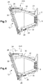
- the figure 1 schematically represents the main components of a head-up display 2 according to the invention, fitted to a motor vehicle.
- a display 2 comprises an image generation unit 4 comprising a light source 6, fixedly mounted on a printed circuit support plate 8.
- the light source is oriented so as to illuminate a front face 10 of a screen backlit 12.
- the backlit display includes a frame 121 surrounding a die 122 consisting of elements whose transmittance varies in a controlled manner over time. More specifically, the matrix 122 is formed of liquid crystal cells.
- each cell is controlled by means of a control module 14 so as to locally and temporarily modify the transmittance of the backlit screen 12, in order to generate a light beam corresponding to at least one information to be displayed under the shape of a pixelated image. This light beam is thus transmitted at the output of a rear face 16 of the backlit screen.
- the virtual image is generated for the driver of the motor vehicle by reflection of the aforementioned light beam on a partially reflective blade 18, also called “combiner”, placed in its field of view. It is thus possible to display information in the driver's field of vision without the latter having to look away from the road followed by the vehicle.
- the partially reflective blade 18 used for this purpose is here separate from the windshield 20 of the motor vehicle, and preferably disposed between the windshield 20 of the vehicle and the eyes 22 of the driver. Alternatively, however, the windshield of the vehicle could provide the function of the partially reflective blade.
- the display 2 also comprises an upstream optical conduit 24A, interposed between the light source 6 and the backlit screen 12, and a downstream optical conduit 24B interposed between the backlit screen 12 and the blade 18.
- upstream and Downstream refers to the direction of propagation of the light emitted by the light source 6.
- the inner face of the optical conduit 24A is configured to reflect the light emitted by the light source 6.
- the upstream and downstream optical channels are positioned from to ensure that no parasitic shadow is formed on the virtual image due to the presence of particles or dust in the light beam emitted by the light source 6.
- the optical ducts 24 form a sheath protection surrounding the light beam emitted by the light source 6.
- the light not transmitted by the matrix 122 generates heat at the front face 10 and rear face 16 of the backlit display 12.
- the optical conduits 24 are contiguous to the backlit display 12 at at their proximal end 25, this heat is confined to the level of the backlit screen.
- the non-renewal of the air inside the optical duct promotes the thermal heating of the backlit screen 12 beyond a so-called critical temperature, from which the operation of the backlit screen is altered or damaged.
- the state of the art proposes to pierce the optical conduit in different places to form air channels allowing the establishment, between the inside and the outside of the optical conduit, of a phenomenon of natural convection of the ambient air.
- this solution has the disadvantage of promoting an accumulation of particles or dust in the duct optical.
- the properties of the light beam emitted by the light source 6 are then altered, in particular its light intensity.
- the invention solves this technical problem by proposing the use of a filtration membrane 28, obstructing each aeration channel 26, so as to prevent an accumulation of particles in the optical conduit.
- the filtration membranes 28 cover the ventilation channels 26 at the outer faces 30 of the optical conduit 24A. More specifically, the filtration membranes 28 are configured to prevent the passage of particles whose smallest dimension is equal to or greater than 0.07 ⁇ m, preferably equal to or greater than 0.1 ⁇ m.
- the filtration membranes 28 comprise an adhesive face allowing their positioning and their maintenance on an outer face 30 of the optical conduit 24A. The filtration membranes 28 thus prevent the introduction of particles or dust into the optical conduit, while allowing a convective movement of the ambient air between the inside and the outside of the optical conduit.
- the filtration membranes 28 are configured to promote a flow of ambient air through the air channels, at an air flow rate equal to or greater than 10 L / h at a pressure of 70 mbar.
- the filtration membranes are also dark in color and configured to prevent ambient light from entering the optical conduit, so as to preserve the intensity of the light beam emitted by the light source 6.
- a filtration membrane 28 according to the invention may for example be a product sold by the company "Gore”, under the reference “Automotive Vents for Exterior Lighting”.
- the optical conduit 24A comprises at least two air channels 26 passing through two walls 32 of the optical conduit vis-à-vis.
- the dimensions and shapes of the air channels 26 are adapted according to the size of the optical conduit 24A and the thermal heat generated by the backlit screen 12 when illuminated by the light source 6.
- the aeration routes delimit passages whose surface at an outer face 30 is between 5x15 mm 2 and 30x90mm 2 , preferably 10x30 mm 2 and 20x60 mm 2 .
- the ventilation ducts 26 are of substantially parallelepipedal shape and each air channel delimits a passage whose volume is between 5x15x40 mm 3 and 30x90x50 mm 3 , preferably 15x30x45 mm 3 and 20x60x45 mm 3 .
- the ventilation channels 26 pass through opposite walls 32 of the optical conduit 24A.
- the ventilation ducts 26 are arranged closer to the proximal end 25 of the optical duct so that the ambient air passing through said ducts flows as close as possible to the backlit screen 12.
- all the airways 26 are located at a distance from the proximal end 25 of the optic conduit 24A, equal to or less than 50%, a distance separating the proximal end 25 of the optic conduit to a distal end 27 of said leads.
- the distal end 27 is opposed to the proximal end 25 of the optic conduit 24A.
- the proximal end 25 is contiguous to the printed circuit 8.
- FIG 4 illustrates now an alternative embodiment of a head-up display according to the invention.
- a fan 34 is arranged on the optical conduit 24A, vis-à-vis an airway 26 obstructed by a filter membrane 28 described above.
- the identical objects in the attached figures are designated by the same references.
- the operation of the fan 34 can be controlled by means of a control unit not shown on the figure 4 , depending on the operation of the display 2 and / or the temperature of the backlit display 12.
- the fan 34 is configured to establish a forced air flow through the optical conduit 24A which is sufficient to allow its cooling and thus avoid its deterioration.
Landscapes
- Physics & Mathematics (AREA)
- General Physics & Mathematics (AREA)
- Optics & Photonics (AREA)
- Instrument Panels (AREA)
Applications Claiming Priority (1)
| Application Number | Priority Date | Filing Date | Title |
|---|---|---|---|
| FR1850954A FR3077650A1 (fr) | 2018-02-05 | 2018-02-05 | Afficheur tete haute pour vehicule automobile |
Publications (1)
| Publication Number | Publication Date |
|---|---|
| EP3521886A1 true EP3521886A1 (de) | 2019-08-07 |
Family
ID=62167506
Family Applications (1)
| Application Number | Title | Priority Date | Filing Date |
|---|---|---|---|
| EP19155618.2A Pending EP3521886A1 (de) | 2018-02-05 | 2019-02-05 | Head-up-display für kraftfahrzeug |
Country Status (2)
| Country | Link |
|---|---|
| EP (1) | EP3521886A1 (de) |
| FR (1) | FR3077650A1 (de) |
Cited By (1)
| Publication number | Priority date | Publication date | Assignee | Title |
|---|---|---|---|---|
| EP3757643A1 (de) * | 2019-06-28 | 2020-12-30 | Valeo Comfort and Driving Assistance | Head-up-display |
Citations (4)
| Publication number | Priority date | Publication date | Assignee | Title |
|---|---|---|---|---|
| JP2003118426A (ja) * | 2001-10-16 | 2003-04-23 | Honda Motor Co Ltd | 車両用ヘッドアップディスプレイ装置 |
| WO2016121269A1 (ja) * | 2015-01-27 | 2016-08-04 | 日本精機株式会社 | 車両用ヘッドアップディスプレイ装置 |
| US20160255748A1 (en) * | 2015-02-27 | 2016-09-01 | Samsung Electronics Co., Ltd. | Electronic Device Having Heat Radiator and Method for Controlling the Electronic Device |
| DE102015016504A1 (de) * | 2015-12-18 | 2017-06-22 | Audi Ag | Anordnung eines HUD-Moduls in einem Kraftfahrzeug |
-
2018
- 2018-02-05 FR FR1850954A patent/FR3077650A1/fr active Pending
-
2019
- 2019-02-05 EP EP19155618.2A patent/EP3521886A1/de active Pending
Patent Citations (4)
| Publication number | Priority date | Publication date | Assignee | Title |
|---|---|---|---|---|
| JP2003118426A (ja) * | 2001-10-16 | 2003-04-23 | Honda Motor Co Ltd | 車両用ヘッドアップディスプレイ装置 |
| WO2016121269A1 (ja) * | 2015-01-27 | 2016-08-04 | 日本精機株式会社 | 車両用ヘッドアップディスプレイ装置 |
| US20160255748A1 (en) * | 2015-02-27 | 2016-09-01 | Samsung Electronics Co., Ltd. | Electronic Device Having Heat Radiator and Method for Controlling the Electronic Device |
| DE102015016504A1 (de) * | 2015-12-18 | 2017-06-22 | Audi Ag | Anordnung eines HUD-Moduls in einem Kraftfahrzeug |
Cited By (1)
| Publication number | Priority date | Publication date | Assignee | Title |
|---|---|---|---|---|
| EP3757643A1 (de) * | 2019-06-28 | 2020-12-30 | Valeo Comfort and Driving Assistance | Head-up-display |
Also Published As
| Publication number | Publication date |
|---|---|
| FR3077650A1 (fr) | 2019-08-09 |
Similar Documents
| Publication | Publication Date | Title |
|---|---|---|
| EP3224669A1 (de) | Rückbeleuchtungsvorrichtung, insbesondere für eine headup-anzeige, und headup-anzeige für kraftfahrzeug | |
| EP3449305B1 (de) | Anzeige mit einem lichtsensor | |
| EP3521886A1 (de) | Head-up-display für kraftfahrzeug | |
| EP3479167B1 (de) | Flüssigkristallbildschirm, bilderzeugende vorrichtung mit einem solchen bildschrim und head-up display mit einer solchen vorrichtung | |
| EP3491444B1 (de) | Bilderzeugungsvorrichtung und zugehörige head-up-anzeige | |
| EP3631563B1 (de) | Head-up-anzeige für kraftfahrzeug | |
| EP3663834A1 (de) | Head-up-display für kraftfahrzeug, das einen radiator zum abkühlen eines hintergrundbeleuchteten bildschirms umfasst | |
| EP3757643B1 (de) | Head-up-display | |
| EP4110640B1 (de) | Head-up-anzeigevorrichtung | |
| EP3663827A1 (de) | Head-up-display | |
| EP3132304A1 (de) | Rückbeleuchtungsvorrichtung, insbesondere für eine headup-anzeige und headup-anzeige für kraftfahrzeuge | |
| WO2024132689A1 (fr) | Dispositif de génération d'images et afficheur tête haute comportant un tel dispositif | |
| EP3928154B1 (de) | Head-up-anzeige mit einer anzeigevorrichtung mit schutz gegen bildschirmüberhitzung | |
| EP4394483B1 (de) | Bilderzeugungsvorrichtung, verfahren zur temperaturverwaltung einer solchen vorrichtung und head-up-anzeige mit dieser vorrichtung | |
| WO2019025470A1 (fr) | Unité de génération d'image et afficheur tête haute muni d'une telle unité de génération d'image | |
| EP3663813B1 (de) | Bilderzeugungsvorrichtung und entsprechendes head-up-display | |
| EP4394482A1 (de) | Bilderzeugungsvorrichtung, verfahren zur temperaturverwaltung einer solchen vorrichtung und head-up-anzeige mit dieser vorrichtung | |
| FR3105452A1 (fr) | Dispositif de génération d’image et afficheur tête haute comprenant un tel dispositif | |
| FR3104319A1 (fr) | Dispositif de génération d’image avec un dispositif de refroidissement et afficheur tête haute associé | |
| EP4423562A1 (de) | Bilderzeugungsvorrichtung | |
| FR3140680A1 (fr) | Afficheur tête-haute | |
| FR3072474A1 (fr) | Dispositif de generation d'images et afficheur tete haute comprenant un tel dispositif | |
| FR3164540A1 (fr) | Dispositif de génération d’images et afficheur tête haute comportant un tel dispositif | |
| EP2936238B1 (de) | Anzeige, insbesondere eine head-up-anzeige, für ein fahrzeug | |
| FR3105451A1 (fr) | Dispositif de génération d’image et afficheur tête haute comprenant un tel dispositif |
Legal Events
| Date | Code | Title | Description |
|---|---|---|---|
| PUAI | Public reference made under article 153(3) epc to a published international application that has entered the european phase |
Free format text: ORIGINAL CODE: 0009012 |
|
| STAA | Information on the status of an ep patent application or granted ep patent |
Free format text: STATUS: THE APPLICATION HAS BEEN PUBLISHED |
|
| AK | Designated contracting states |
Kind code of ref document: A1 Designated state(s): AL AT BE BG CH CY CZ DE DK EE ES FI FR GB GR HR HU IE IS IT LI LT LU LV MC MK MT NL NO PL PT RO RS SE SI SK SM TR |
|
| AX | Request for extension of the european patent |
Extension state: BA ME |
|
| STAA | Information on the status of an ep patent application or granted ep patent |
Free format text: STATUS: REQUEST FOR EXAMINATION WAS MADE |
|
| 17P | Request for examination filed |
Effective date: 20200207 |
|
| RBV | Designated contracting states (corrected) |
Designated state(s): AL AT BE BG CH CY CZ DE DK EE ES FI FR GB GR HR HU IE IS IT LI LT LU LV MC MK MT NL NO PL PT RO RS SE SI SK SM TR |
|
| STAA | Information on the status of an ep patent application or granted ep patent |
Free format text: STATUS: EXAMINATION IS IN PROGRESS |
|
| 17Q | First examination report despatched |
Effective date: 20220607 |
|
| RAP3 | Party data changed (applicant data changed or rights of an application transferred) |
Owner name: VALEO COMFORT AND DRIVING ASSISTANCE |
|
| P01 | Opt-out of the competence of the unified patent court (upc) registered |
Effective date: 20230528 |
|
| RAP3 | Party data changed (applicant data changed or rights of an application transferred) |
Owner name: VALEO COMFORT AND DRIVING ASSISTANCE |