EP3521910B1 - Vorrichtung mit variabler optischer transmission und zugehöriges steuerungsverfahren - Google Patents
Vorrichtung mit variabler optischer transmission und zugehöriges steuerungsverfahren Download PDFInfo
- Publication number
- EP3521910B1 EP3521910B1 EP18305120.0A EP18305120A EP3521910B1 EP 3521910 B1 EP3521910 B1 EP 3521910B1 EP 18305120 A EP18305120 A EP 18305120A EP 3521910 B1 EP3521910 B1 EP 3521910B1
- Authority
- EP
- European Patent Office
- Prior art keywords
- transmission
- target
- duration
- value
- optics
- Prior art date
- Legal status (The legal status is an assumption and is not a legal conclusion. Google has not performed a legal analysis and makes no representation as to the accuracy of the status listed.)
- Active
Links
Images


Classifications
-
- G—PHYSICS
- G02—OPTICS
- G02F—OPTICAL DEVICES OR ARRANGEMENTS FOR THE CONTROL OF LIGHT BY MODIFICATION OF THE OPTICAL PROPERTIES OF THE MEDIA OF THE ELEMENTS INVOLVED THEREIN; NON-LINEAR OPTICS; FREQUENCY-CHANGING OF LIGHT; OPTICAL LOGIC ELEMENTS; OPTICAL ANALOGUE/DIGITAL CONVERTERS
- G02F1/00—Devices or arrangements for the control of the intensity, colour, phase, polarisation or direction of light arriving from an independent light source, e.g. switching, gating or modulating; Non-linear optics
- G02F1/01—Devices or arrangements for the control of the intensity, colour, phase, polarisation or direction of light arriving from an independent light source, e.g. switching, gating or modulating; Non-linear optics for the control of the intensity, phase, polarisation or colour
- G02F1/13—Devices or arrangements for the control of the intensity, colour, phase, polarisation or direction of light arriving from an independent light source, e.g. switching, gating or modulating; Non-linear optics for the control of the intensity, phase, polarisation or colour based on liquid crystals, e.g. single liquid crystal display cells
- G02F1/133—Constructional arrangements; Operation of liquid crystal cells; Circuit arrangements
- G02F1/13306—Circuit arrangements or driving methods for the control of single liquid crystal cells
- G02F1/13318—Circuits comprising a photodetector
-
- G—PHYSICS
- G02—OPTICS
- G02C—SPECTACLES; SUNGLASSES OR GOGGLES INSOFAR AS THEY HAVE THE SAME FEATURES AS SPECTACLES; CONTACT LENSES
- G02C11/00—Non-optical adjuncts; Attachment thereof
- G02C11/10—Electronic devices other than hearing aids
-
- G—PHYSICS
- G02—OPTICS
- G02C—SPECTACLES; SUNGLASSES OR GOGGLES INSOFAR AS THEY HAVE THE SAME FEATURES AS SPECTACLES; CONTACT LENSES
- G02C7/00—Optical parts
- G02C7/10—Filters, e.g. for facilitating adaptation of the eyes to the dark; Sunglasses
- G02C7/101—Filters, e.g. for facilitating adaptation of the eyes to the dark; Sunglasses having an electro-optical light valve
-
- G—PHYSICS
- G02—OPTICS
- G02C—SPECTACLES; SUNGLASSES OR GOGGLES INSOFAR AS THEY HAVE THE SAME FEATURES AS SPECTACLES; CONTACT LENSES
- G02C7/00—Optical parts
- G02C7/10—Filters, e.g. for facilitating adaptation of the eyes to the dark; Sunglasses
- G02C7/102—Photochromic filters
-
- G—PHYSICS
- G02—OPTICS
- G02F—OPTICAL DEVICES OR ARRANGEMENTS FOR THE CONTROL OF LIGHT BY MODIFICATION OF THE OPTICAL PROPERTIES OF THE MEDIA OF THE ELEMENTS INVOLVED THEREIN; NON-LINEAR OPTICS; FREQUENCY-CHANGING OF LIGHT; OPTICAL LOGIC ELEMENTS; OPTICAL ANALOGUE/DIGITAL CONVERTERS
- G02F1/00—Devices or arrangements for the control of the intensity, colour, phase, polarisation or direction of light arriving from an independent light source, e.g. switching, gating or modulating; Non-linear optics
- G02F1/01—Devices or arrangements for the control of the intensity, colour, phase, polarisation or direction of light arriving from an independent light source, e.g. switching, gating or modulating; Non-linear optics for the control of the intensity, phase, polarisation or colour
- G02F1/13—Devices or arrangements for the control of the intensity, colour, phase, polarisation or direction of light arriving from an independent light source, e.g. switching, gating or modulating; Non-linear optics for the control of the intensity, phase, polarisation or colour based on liquid crystals, e.g. single liquid crystal display cells
- G02F1/133—Constructional arrangements; Operation of liquid crystal cells; Circuit arrangements
- G02F1/13306—Circuit arrangements or driving methods for the control of single liquid crystal cells
-
- G—PHYSICS
- G02—OPTICS
- G02F—OPTICAL DEVICES OR ARRANGEMENTS FOR THE CONTROL OF LIGHT BY MODIFICATION OF THE OPTICAL PROPERTIES OF THE MEDIA OF THE ELEMENTS INVOLVED THEREIN; NON-LINEAR OPTICS; FREQUENCY-CHANGING OF LIGHT; OPTICAL LOGIC ELEMENTS; OPTICAL ANALOGUE/DIGITAL CONVERTERS
- G02F1/00—Devices or arrangements for the control of the intensity, colour, phase, polarisation or direction of light arriving from an independent light source, e.g. switching, gating or modulating; Non-linear optics
- G02F1/01—Devices or arrangements for the control of the intensity, colour, phase, polarisation or direction of light arriving from an independent light source, e.g. switching, gating or modulating; Non-linear optics for the control of the intensity, phase, polarisation or colour
- G02F1/15—Devices or arrangements for the control of the intensity, colour, phase, polarisation or direction of light arriving from an independent light source, e.g. switching, gating or modulating; Non-linear optics for the control of the intensity, phase, polarisation or colour based on an electrochromic effect
- G02F1/163—Operation of electrochromic cells, e.g. electrodeposition cells; Circuit arrangements therefor
-
- G—PHYSICS
- G02—OPTICS
- G02F—OPTICAL DEVICES OR ARRANGEMENTS FOR THE CONTROL OF LIGHT BY MODIFICATION OF THE OPTICAL PROPERTIES OF THE MEDIA OF THE ELEMENTS INVOLVED THEREIN; NON-LINEAR OPTICS; FREQUENCY-CHANGING OF LIGHT; OPTICAL LOGIC ELEMENTS; OPTICAL ANALOGUE/DIGITAL CONVERTERS
- G02F1/00—Devices or arrangements for the control of the intensity, colour, phase, polarisation or direction of light arriving from an independent light source, e.g. switching, gating or modulating; Non-linear optics
- G02F1/29—Devices or arrangements for the control of the intensity, colour, phase, polarisation or direction of light arriving from an independent light source, e.g. switching, gating or modulating; Non-linear optics for the control of the position or the direction of light beams, i.e. deflection
Definitions
- the remote configuring unit RCU may also be used to test different parameters on a user of the variable transmission device in order to adapt the response duration of the variable transmission lens or optics to its preferences.
- the remote configuring unit RCU may be used to test different response durations depending on whether the transmission of the variable transmission device is being lowered or increased or depending on the initial and target transmission values.
- the response duration may be controlled in different ways, which are illustrated in the remaining of the description.
- the variable transmission device 2 may for example be operated in automatic mode.
- the ambient light sensor 8 measures periodically the illuminance of the exterior environment and indicates when a change in illuminance in the exterior environment occurs.
- the ambient light sensor 8 may also provide an indication of the currently measured illuminance.
- the value of the currently measured illuminance may be used by the processor PROC of the control unit 5 to calculate the target transmission value.
- the processor PROC then generates one or more command signals for varying the optical transmission between the initial transmission value and the target transmission value which are sent to the voltage driver 7.
- the voltage driver 7 generates a corresponding voltage signal that is applied to the command electrodes of the electrochromic or liquid crystal lenses 4a, 4b.
- Figure 3 represents a method for controlling a variable transmission device comprising electrochromic or liquid crystal optics in automatic mode according to an embodiment. The method described here enables to control the response duration of the variable optical transmission device.
- the response duration may be varied in different ways.
- a transition function having a predetermined duration may be used for varying the optical transmission between the initial transmission value and the target transmission value.
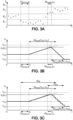
- variable optical transmission device as described in reference to figures 1 and 2 , according to an embodiment further illustrated in reference to figures 3A, 3B, 3C .
- Figures 3A, 3B and 3C illustrate an embodiment in which the change in illuminance is detected for different illumination ranges P1, P2, P3, ..., Pn with two different temporization durations ⁇ t tempo,Bl and ⁇ t tempo,Dn .
- the optical transmission values vary between the initial transmission value and the target transmission value according to a transition function having a total transition duration depending on the initial transmission values and the target transmission values considered.
- the transition function is represented as a linear transition function. Other forms of transition functions may be considered as will be described later.
- Figure 3A represents an example of illuminance measured by an ambient light sensor 8.
- Figure 3B represents schematically the transmission values of the variable transmission device as controlled by the control unit and figure 3C illustrates an example of the transmission values sent by the command signals of the control unit to the voltage converter.
- the values defining the illuminance range may be adapted to the conditions of use. By associating to each illuminance range a single target transmission value, the electrical consumption of the variable transmission optics may be decreased. In an alternative, the target transmission value may be determined as a function of the currently measured illuminance transmitted by the sensor to the processor.
- the method for controlling the electrochromic or the liquid crystal optics is as follows.
- an initial illuminance value is measured and transmitted to the processor PROC of the control unit 5 via the input interface IN.
- the processor PROC determines an illuminance range for which the initial illuminance value is comprised between the minimum and maximum illuminance values of one of the predefined illuminance ranges.
- the corresponding minimum and maximum illuminance values of the current illuminance range are then sent to a memory of the sensor 8.
- the processor of the control unit 5 also sends the values of the first and second temporization durations ⁇ t tempo,Dn and ⁇ t tempo,Bl via the output interface OUT of the control unit 5.
- the senor 8 which also comprises an integrated microprocessor, measures periodically the illuminance in order to detect a change of illuminance when the currently measured illuminance is greater than a maximum illuminance value of current illumination range during the first temporization duration ⁇ t tempo,Dn or when the currently measured illuminance is less than a minimum illuminance value of the current illumination range during the second temporization duration ⁇ t tempo,Bl .
- the value of the currently, measured illuminance i.e. the last measured illuminance
- the processor PROC of the control unit 5 via the input interface IN.
- the processor determines which illuminance range corresponds to the measured illuminance and determines the target transmission value corresponding to that illuminance range.
- the processor then generates one or more command signals for varying the optical transmission between the initial transmission value before detection of the change of illuminance and the target transmission value, the transmission value varying according to (1), wherein the transition function is a linear transition function.
- the processor sends to the sensor 8 the updated values of the minimum and maximum illuminance of the actual illuminance range and the sensor measures periodically the illuminance as described in step 5100 until another change of illuminance is detected.
- Figure 3A shows an example of illuminance which is periodically measured by the ambient light sensor 8.
- the illuminance is first comprised within range P2 and is then lowered to be comprised within range P1 and further increases to be within range P3.
- the transmission value of the variable transmission lens is set to have a value of ⁇ v,2 because the measured illuminance value is within range P2 as can be seen in Figure 3B .
- the processor generates one or more command signals for varying the transmission between ⁇ v,2 and ⁇ v,1 according to a linear transition function having a total transition duration ⁇ t trans [ ⁇ v2, ⁇ v1] which are sent to the voltage driver 7.
- the processor also sends a signal comprising the minimum and maximum illuminance values Imin,1, Imax,1 of the illuminance range P1 to the sensor 8 via the input interface IN.
- the processor generates one or more command signals for varying the transmission between ⁇ v(t1) and ⁇ v,3 according to a linear transition function having a total transition duration ⁇ t trans [ ⁇ v(t1), ⁇ v3] which is sent to the voltage driver 7.
- the processor also sends a signal comprising the minimum and maximum illuminance values Imin,3, Imax,3 of the illuminance range P3 to the sensor 8 via the input interface IN.
- each of the response durations ⁇ t Bl , ⁇ t Dn comprises the temporization duration ⁇ t tempo,Bl , ⁇ t tempo,Dn and the total transition duration ⁇ t trans [ ⁇ v2), ⁇ v1], ⁇ t trans [ ⁇ v(t1), ⁇ v3] of the transition function used, respectively.
- the first temporization duration ⁇ t tempo,Dn is different from the second temporization duration ⁇ t tempo,B1 and depends of the sign of a difference between the initial transmission value and the target transmission value.
- a temporization duration ⁇ t tempo,Bl is applied and if the target transmission value is lower than the initial transmission value, for example when ⁇ v,3 is lower than ⁇ v(t1), a temporization duration ⁇ t tempo,Dn is applied.
- the first and second temporization durations may be determined as a function of the illuminance measured outside the current illuminance range used for detection shortly after the illuminance has changed.
- the total transition duration ⁇ t trans here ⁇ t trans [ ⁇ v2, ⁇ v1] and ⁇ t trans [ ⁇ v(t1), ⁇ v3], are chosen greater than or equal to 300 milliseconds and lower than or equal to 10 500 milliseconds. Those values have been tested on wearers of eyeglasses comprising variable transmission devices and wearers acknowledged an improved visual comfort.
- the first and second temporization durations At tempo,Dn , ⁇ t tempo,Bl may be equal to each other or equal to zero.
- the response duration corresponds to the total transition duration ⁇ t trans of the transition function f ⁇ V ( t i ), ⁇ V,target ( t ).
- the value of the total transition duration ⁇ t trans is dependent of the initial transmission value and of the target transmission value.
- the value of the total transition duration ⁇ t trans may depend on the absolute value of the difference between the initial transmission value and the target transmission value and/or the value of the total transition duration may depend on the sign of the difference between the initial transmission value and the target transmission value.
- the value of the total transition duration may be different depending on whether the transmission is being increased or lowered.
- a total transition duration ⁇ t trans,Dn may be applied.
- a total transition duration ⁇ t trans,B1 may be applied.
- the values of the total transition durations ⁇ t trans,Dn , ⁇ t trans,B1 are constant and ⁇ t trans,Dn is different from ⁇ t trans,Bl .
- the value of the total transition duration to choose only depends on the sign of the difference between the initial transmission value and the target transmission value.
- the total transition durations ⁇ t trans,Dn , ⁇ t trans,Bl may vary.
- the value of the total transition duration to choose depends on both the sign and the absolute value of the difference between the initial transmission value and the target transmission value. Accordingly, a different transition duration ⁇ t trans,Bl may be used for example when the optical transmission increases from ⁇ v,3 to ⁇ v,2 and from ⁇ v,3 to ⁇ v,1.
- the total transition duration ⁇ t trans,Dn used for lowering the transmission for example from ⁇ v,2 to ⁇ v,3, is different from the total transition duration ⁇ t trans,Bl used for increasing the transmission from ⁇ v,3 to ⁇ v,2.
- TDn is thus different from tBl such that the exponential transition function has a different time constant T ⁇ V ( t i ), ⁇ V,target depending on whether the transmission is increased or lowered, independently of the initial and target transmission values considered.
- the visual comfort is increased when the response duration (dependent of T Bl ) applied when the transmission of the eyewear is increased, i.e. when the variable transmission optics bleaches, is different from the response duration (dependent of T Dn ) applied when the transmission of the eyewear decreases, i.e. when the variable transmission optics darkens.
- the couples (T Dn , T Bl ) are not situated on the linear function having a slope of 1.
- variable transmission optics is an electrochromic or a liquid crystal lens and the response duration is controlled in automatic mode by controlling the optical transmission of the variable transmission optics.
- the response duration of the variable transmission is controlled by applying a predetermined temperature during a predetermined duration.
- the response duration may be determined as a function of the initial transmission value and the target transmission value.
- the initial transmission value may be measured by a sensor configured to measure the transmission value of the lens or optics.
- the target transmission value may be inferred from a measurement of the illuminance measured by the ambient light sensor.
- the response duration and more particularly the temperature Temp and the duration of heating ⁇ t heat , may be determined.
- the temperature T and the heating duration ⁇ t heat is set by the controller, and more particularly by the command signals sent by the control unit to the voltage driver 7.
- the temperature T intended to be applied to the photochromic lens is set by applying a corresponding voltage between the two electrodes of the transparent heater.
Landscapes
- Physics & Mathematics (AREA)
- Health & Medical Sciences (AREA)
- Ophthalmology & Optometry (AREA)
- General Physics & Mathematics (AREA)
- Optics & Photonics (AREA)
- Nonlinear Science (AREA)
- General Health & Medical Sciences (AREA)
- Chemical & Material Sciences (AREA)
- Crystallography & Structural Chemistry (AREA)
- Mathematical Physics (AREA)
- Otolaryngology (AREA)
- Acoustics & Sound (AREA)
- Electrochromic Elements, Electrophoresis, Or Variable Reflection Or Absorption Elements (AREA)
- Eyeglasses (AREA)
- Liquid Crystal (AREA)
- Optical Communication System (AREA)
Claims (11)
- Vorrichtung mit variabler optischer Transmission (2), die Folgendes umfasst:- eine variable Transmissionsoptik (4a, 4b), die in der Lage ist, eine optische Transmission zwischen einem anfänglichen Transmissionswert (τv (ti )) und einem Zieltransmissionswert (τv,target ) zu variieren, und- eine Steuereinheit (5), ausgelegt zum Steuern eines Transmissionsparameters der variablen Transmissionsoptik, wobei die Steuereinheit (5) ausgelegt ist zum Steuern einer Antwortdauer der variablen Transmissionsoptik als eine Funktion des anfänglichen Transmissionswerts (τv (ti )) und des Zieltransmissionswertes (Tv,target ),wobei die Steuereinheit (5) ausgelegt ist zum Steuern der Antwortdauer in Abhängigkeit vom Vorzeichen einer Differenz zwischen dem anfänglichen Transmissionswert (τv (ti )) und dem Zieltransmissionswert (τv,target ), wobei die Steuereinheit ausgelegt ist zum Steuern:∘ einer ersten Antwortdauer (ΔtDn) zum Verringern einer optischen Transmission der variablen Transmissionsoptik von einem anfänglichen Transmissionswert (τ v (ti )) auf einen Zieltransmissionswert (τv,target ), und∘ einer zweiten Antwortdauer (ΔtBl) zum Erhöhen der optischen Transmission vom anfänglichen Transmissionswert (τv (ti )) auf den Zieltransmissionswert (τv,target ),wobei die erste Antwortdauer (ΔtDn ) verschieden von der zweiten Antwortdauer (ΔtBl ) ist,wobei die variable Transmissionsoptik (4a, 4b) unter einer aus einer elektrochromen Optik und einer Flüssigkristalloptik ausgewählt wird und der Transmissionsparameter der variablen Transmissionsoptik eine optische Transmission der variablen Transmissionsoptik ist,wobei die Steuereinheit ausgelegt ist zum Steuern der optischen Transmission durch Erzeugen eines oder mehrerer Befehlssignale zum Variieren der optischen Transmission zwischen dem anfänglichen Transmissionswert vor Detektion der Änderung der Beleuchtungsstärke und dem Zieltransmissionswert, sodass der optische Transmissionswert variiert entsprechend:
 wobei τv (ti ) der anfängliche Transmissionswert zu einem Zeitpunkt t=ti ist,τ v (ti + t) der aktuelle Transmissionswert zu einem Zeitpunkt ti + t ist,und f τ V (ti ),τ V,target (t) eine Übergangsfunktion ist, die von dem anfänglichen Transmissionswert τV (ti ) und dem Zieltransmissionswert (τV,target ) abhängt, so definiert, dass:
 wobei die Übergangsfunktion eine Gesamtübergangsdauer aufweist, die durch das Zeitintervall definiert ist, während dessen die Übergangsfunktion einen Transmissionswert von 0,95 (τV,target - τv (ti )) erreicht, und wobei die Übergangsfunktion eine lineare Übergangsfunktion ist, undwobei jede aus der ersten und der zweiten Antwortdauer die entsprechende Gesamtübergangsdauer umfasst.
 - Vorrichtung mit variabler optischer Transmission nach Anspruch 1, wobei die Antwortdauer entsprechend den Präferenzen des Trägers oder einer Gruppe von Trägern ausgewählt wird.
- Vorrichtung mit variabler optischer Transmission (2) nach Anspruch 1 oder 2, die ferner einen Umgebungslichtsensor umfasst, der ausgelegt ist zum periodischen Messen der Beleuchtungsstärke und zum Detektieren einer Änderung in der Beleuchtungsstärke, wobei:- die Änderung der Beleuchtungsstärke detektiert wird, wenn die gemessene Beleuchtungsstärke während einer vorbestimmten Temporisierungsdauer verschieden von einer Referenzbeleuchtungsstärke ist,- die Steuereinheit (5) ausgelegt ist zum Steuern, bei Detektion der Änderung der Beleuchtungsstärke nach der vorbestimmten Temporisierungsdauer, eines Transmissionsparameters der variablen Transmissionsoptik, und- die Antwortdauer die vorbestimmte Temporisierungsdauer umfasst.
- Vorrichtung mit variabler optischer Transmission (2) nach Anspruch 1, wobei die Gesamtübergangsdauer so ausgewählt wird, dass sie größer als oder gleich 300 Millisekunden und kleiner als oder gleich 10500 Millisekunden ist.
- Vorrichtung mit variabler optischer Transmission nach einem der Ansprüche 1 bis 4, wobei- wenn sich die optische Transmission von einem ersten anfänglichen Transmissionswert auf einen ersten Zieltransmissionswert verringert, die optische Transmission entsprechend einer ersten Übergangsfunktion mit einer ersten Gesamtübergangsdauer variiert und- wenn sich die optische Transmission von einem zweiten anfänglichen Transmissionswert auf einen zweiten Zieltransmissionswert erhöht, die optische Transmission entsprechend einer zweiten Übergangsfunktion mit einer zweiten Gesamtübergangsdauer variiert, unddie zweite Gesamtübergangsdauer verschieden von der ersten Gesamtübergangsdauer ist.
- Vorrichtung mit variabler optischer Transmission nach Anspruch 5, wobei der erste anfängliche Transmissionswert gleich dem zweiten Zieltransmissionswert ist und der erste Zieltransmissionswert gleich dem zweiten anfänglichen Transmissionswert ist.
- Vorrichtung mit variabler optischer Transmission (2) nach einem der Ansprüche 1 bis 3, wobei die variable Transmissionsoptik eine photochrome Optik ist, die Vorrichtung mit variabler Transmission ferner ein transparentes Heizelement umfasst, die Steuereinheit ausgelegt ist zum Steuern der Antwortdauer der photochromen Optik durch Einstellen einer vorbestimmten Temperatur (T; TempDn, TempBl) während einer vorbestimmten Heizdauer (Δtheat; Δtheat,Dn, Δtheat,Bl), wobei die vorbestimmte Temperatur (Temp; TempDn, TempBl) und die Heizdauer (Δtheat; Δtheat,Dn, Δtheat,Bl) als eine Funktion des anfänglichen Transmissionswerts τV (ti ) und des Zieltransmissionswerts (τV,target ) bestimmt werden.
- Vorrichtung mit variabler optischer Transmission nach einem der vorhergehenden Ansprüche, wobei die Vorrichtung mit variabler Transmission ferner Folgendes umfasst:- eine entfernte Konfigurationseinheit, dazu ausgelegt, Folgendes an die Steuereinheit zu senden:wobei die Konfigurationseinheit zum Testen von unterschiedlicher erster Antwortdauer, zweiter Antwortdauer auf einem Träger der Vorrichtung mit variabler Transmission oder zum Konfigurieren der Vorrichtung mit variabler Transmission mit einer ersten Antwortdauer und einer zweiten Antwortdauer entsprechend den Präferenzen des Trägers verwendet werden soll.∘ zumindest eine erste Antwortdauer und eine zweite Antwortdauer,
- Verfahren zum Steuern einer Vorrichtung mit variabler optischer Transmission, das Folgendes umfasst:- Steuern eines Transmissionsparameters einer variablen Transmissionsoptik der Vorrichtung mit variabler Transmission (S200),wobei das Verfahren ferner Folgendes umfasst:- Steuern einer Antwortdauer der variablen Transmissionsoptik als eine Funktion eines anfänglichen Transmissionswerts (τV (ti )) und eines Zieltransmissionswerts (τV,target ),wobei das Verfahren ferner Folgendes umfasst:- Steuern der Antwortdauer in Abhängigkeit von einem Vorzeichen einer Differenz zwischen dem anfänglichen Transmissionswert (τV (ti )) und dem Zieltransmissionswert (τV,target ), Folgendes umfassend:- Steuern einer ersten Antwortdauer (ΔtDn ) zum Verringern einer optischen Transmission der variablen Transmissionsoptik von einem anfänglichen Transmissionswert (τ V (ti )) auf einen Zieltransmissionswert (τV,target ), und- Steuern einer zweiten Antwortdauer (ΔtBl ) zum Erhöhen der optischen Transmission von einem anfänglichen Transmissionswert (τV (ti )) auf einen Zieltransmissionswert (τV,target ),- wobei die erste Antwortdauer (ΔtDn ) verschieden von der zweiten Antwortdauer (ΔtBl ) ist,wobei die variable Transmissionsoptik (4a, 4b) unter einer aus einer elektrochromen Optik und einer Flüssigkristalloptik ausgewählt wird und der Transmissionsparameter der variablen Transmissionsoptik eine optische Transmission der variablen Transmissionsoptik ist,wobei die Steuereinheit ausgelegt ist zum Steuern der optischen Transmission durch Erzeugen eines oder mehrerer Befehlssignale zum Variieren der optischen Transmission zwischen dem anfänglichen Transmissionswert vor Detektion der Änderung der Beleuchtungsstärke und dem Zieltransmissionswert, sodass der optische Transmissionswert variiert entsprechend:
 wobei τV (ti ) der anfängliche Transmissionswert zu einem Zeitpunkt t=ti ist,τV (ti + t) der aktuelle Transmissionswert zu einem Zeitpunkt ti + t ist,und f τ V (ti ),τ V,target (t) eine Übergangsfunktion ist, die von dem anfänglichen Transmissionswert τV (ti ) und dem Zieltransmissionswert (τV,target ) abhängt, so definiert, dass:
 wobei die Übergangsfunktion eine Gesamtübergangsdauer aufweist, die durch das Zeitintervall definiert ist, während dessen die Übergangsfunktion einen Transmissionswert von 0,95 (τV,target - τV (ti )) erreicht, und wobei die Übergangsfunktion eine lineare Übergangsfunktion ist, und- wobei jede aus der ersten und der zweiten Antwortdauer die entsprechende Gesamtübergangsdauer umfasst.
 - Verfahren zur Steuerung einer Vorrichtung mit variabler optischer Transmission nach Anspruch 9, wobei die Antwortdauer entsprechend den Präferenzen des Trägers ausgewählt wird.
- Computerprogramm, umfassend eine oder mehrere gespeicherte Sequenzen von Anweisungen, auf das durch einen Prozessor zugegriffen werden kann, der mit einer variablen Transmissionsoptik verbunden ist, und das, wenn durch den Prozessor ausgeführt, den Prozessor veranlasst, die Schritte des Verfahrens nach einem der Ansprüche 9 oder 10 auszuführen.
Priority Applications (6)
| Application Number | Priority Date | Filing Date | Title |
|---|---|---|---|
| EP18305120.0A EP3521910B1 (de) | 2018-02-06 | 2018-02-06 | Vorrichtung mit variabler optischer transmission und zugehöriges steuerungsverfahren |
| CN201980010053.2A CN111670405B (zh) | 2018-02-06 | 2019-02-05 | 可变光学透射率装置以及相关联的控制方法 |
| KR1020207020505A KR102678599B1 (ko) | 2018-02-06 | 2019-02-05 | 가변 광 투과율 장치 및 관련 제어 방법 |
| JP2020542447A JP7576980B2 (ja) | 2018-02-06 | 2019-02-05 | 可変光透過デバイス及び関連する制御方法 |
| PCT/EP2019/052812 WO2019154821A1 (en) | 2018-02-06 | 2019-02-05 | Variable optical transmission device and associated control method |
| US16/964,490 US11960157B2 (en) | 2018-02-06 | 2019-02-05 | Variable optical transmission device and associated control method |
Applications Claiming Priority (1)
| Application Number | Priority Date | Filing Date | Title |
|---|---|---|---|
| EP18305120.0A EP3521910B1 (de) | 2018-02-06 | 2018-02-06 | Vorrichtung mit variabler optischer transmission und zugehöriges steuerungsverfahren |
Publications (2)
| Publication Number | Publication Date |
|---|---|
| EP3521910A1 EP3521910A1 (de) | 2019-08-07 |
| EP3521910B1 true EP3521910B1 (de) | 2024-07-03 |
Family
ID=61244507
Family Applications (1)
| Application Number | Title | Priority Date | Filing Date |
|---|---|---|---|
| EP18305120.0A Active EP3521910B1 (de) | 2018-02-06 | 2018-02-06 | Vorrichtung mit variabler optischer transmission und zugehöriges steuerungsverfahren |
Country Status (6)
| Country | Link |
|---|---|
| US (1) | US11960157B2 (de) |
| EP (1) | EP3521910B1 (de) |
| JP (1) | JP7576980B2 (de) |
| KR (1) | KR102678599B1 (de) |
| CN (1) | CN111670405B (de) |
| WO (1) | WO2019154821A1 (de) |
Families Citing this family (3)
| Publication number | Priority date | Publication date | Assignee | Title |
|---|---|---|---|---|
| EP4172689B1 (de) * | 2020-06-26 | 2025-12-10 | Essilor International | Brillenvorrichtung und verfahren zum antrieb einer ophthalmischen linse mit variabler transmission |
| CN116601542A (zh) * | 2020-09-21 | 2023-08-15 | 苹果公司 | 图像捕获和可见光透射的同步 |
| EP3985429B1 (de) * | 2020-10-16 | 2025-12-03 | Essilor International | Dynamische übertragungswertregelung |
Citations (2)
| Publication number | Priority date | Publication date | Assignee | Title |
|---|---|---|---|---|
| DE102014014577A1 (de) * | 2014-09-30 | 2016-03-31 | Carl Zeiss Ag | Phototropes Brillenglas und Brille, aufweisend ein solches Glas |
| EP3072011A1 (de) * | 2013-11-20 | 2016-09-28 | Ashwin-Ushas Corporation, Inc. | Verfahren und vorrichtung zur steuerung elektrochromer vorrichtungen |
Family Cites Families (17)
| Publication number | Priority date | Publication date | Assignee | Title |
|---|---|---|---|---|
| US4279474A (en) * | 1980-03-25 | 1981-07-21 | Belgorod Barry M | Spectacle lens having continuously variable controlled density and fast response time |
| JPS62118316A (ja) * | 1985-11-19 | 1987-05-29 | Jiesu:Kk | サングラス |
| DE69129759D1 (de) | 1990-12-14 | 1998-08-13 | Humphrey Eng Inc | Verfahren und vorrichtung zur steuerung des grades der helligkeitsempfindung mittels einer zeitveränderlichen blende |
| GB9201124D0 (en) * | 1992-01-20 | 1992-03-11 | Crystalens Ltd | Liquid crystal lens circuit |
| US5671035A (en) * | 1995-06-07 | 1997-09-23 | Barnes; Elwood E. | Light intensity reduction apparatus and method |
| JP3984878B2 (ja) * | 2002-07-09 | 2007-10-03 | キヤノン株式会社 | 光量調節装置、該光量調節装置を有する撮像装置 |
| US8254013B2 (en) * | 2011-03-16 | 2012-08-28 | Soladigm, Inc. | Controlling transitions in optically switchable devices |
| EP2798397B1 (de) * | 2011-12-27 | 2016-07-13 | Merck Patent GmbH | Vorrichtung zur temperaturabhängigen regulierung des energie-durchtritts durch eine lichtdurchlässige fläche |
| EP2914990B1 (de) | 2012-11-01 | 2020-02-19 | Essilor International | Thermisch beeinflusste veränderliche färbevorrichtung |
| JP2014238565A (ja) * | 2013-03-11 | 2014-12-18 | キヤノン株式会社 | エレクトロクロミック素子、撮像光学系、撮像装置および窓材 |
| KR102153599B1 (ko) * | 2013-11-18 | 2020-09-08 | 삼성전자주식회사 | 머리 착용형 디스플레이 장치 및 머리 착용형 디스플레이 장치의 광 투과율 변경 방법 |
| US20160041447A1 (en) * | 2014-08-05 | 2016-02-11 | Canon Kabushiki Kaisha | Method and apparatus for driving an electrochromic element |
| DE102014014544A1 (de) | 2014-09-30 | 2015-04-02 | Daimler Ag | Lokalisierung von Objekten |
| WO2016107866A1 (en) * | 2014-12-30 | 2016-07-07 | Essilor International (Compagnie Generale D'optique) | Management system and method of an active device |
| CN107924098A (zh) * | 2015-07-10 | 2018-04-17 | 依视路国际公司 | 具有改善的振幅变化单元的眼科装置 |
| US11226499B2 (en) | 2015-07-10 | 2022-01-18 | Essilor International | Plateau-based control of the transmission of a variable transmission lens |
| AU2016374204B2 (en) * | 2015-12-15 | 2019-05-30 | Ricoh Company, Ltd. | Electrochromic apparatus |
-
2018
- 2018-02-06 EP EP18305120.0A patent/EP3521910B1/de active Active
-
2019
- 2019-02-05 CN CN201980010053.2A patent/CN111670405B/zh active Active
- 2019-02-05 KR KR1020207020505A patent/KR102678599B1/ko active Active
- 2019-02-05 WO PCT/EP2019/052812 patent/WO2019154821A1/en not_active Ceased
- 2019-02-05 JP JP2020542447A patent/JP7576980B2/ja active Active
- 2019-02-05 US US16/964,490 patent/US11960157B2/en active Active
Patent Citations (2)
| Publication number | Priority date | Publication date | Assignee | Title |
|---|---|---|---|---|
| EP3072011A1 (de) * | 2013-11-20 | 2016-09-28 | Ashwin-Ushas Corporation, Inc. | Verfahren und vorrichtung zur steuerung elektrochromer vorrichtungen |
| DE102014014577A1 (de) * | 2014-09-30 | 2016-03-31 | Carl Zeiss Ag | Phototropes Brillenglas und Brille, aufweisend ein solches Glas |
Also Published As
| Publication number | Publication date |
|---|---|
| CN111670405A (zh) | 2020-09-15 |
| US20210033891A1 (en) | 2021-02-04 |
| CN111670405B (zh) | 2022-10-18 |
| KR102678599B1 (ko) | 2024-06-26 |
| US11960157B2 (en) | 2024-04-16 |
| WO2019154821A1 (en) | 2019-08-15 |
| EP3521910A1 (de) | 2019-08-07 |
| JP2021513110A (ja) | 2021-05-20 |
| JP7576980B2 (ja) | 2024-11-01 |
| KR20200112838A (ko) | 2020-10-05 |
Similar Documents
| Publication | Publication Date | Title |
|---|---|---|
| US20230019843A1 (en) | Calibration of electrical parameters in optically switchable windows | |
| US11960157B2 (en) | Variable optical transmission device and associated control method | |
| US10539812B2 (en) | Eyewear control system and method, and an eyewear device | |
| US8018644B2 (en) | Control of electrochromic device | |
| US9477096B2 (en) | Optical-characteristics adjusting system for sunglasses or goggles and sunglasses and goggles equipped therewith | |
| EP2839338B1 (de) | System und verfahren zur steuerung einer optischen filteranordnung | |
| US11226499B2 (en) | Plateau-based control of the transmission of a variable transmission lens | |
| WO2022148335A1 (zh) | 电致变色器件的调控方法及电子设备 | |
| CN110383147A (zh) | 眼睛佩戴物 | |
| EP1626306A3 (de) | Steuerungssystem für elektrochrome Vorrichtungen | |
| US20170068112A1 (en) | Electronically switchable optical device with a multi-functional optical control apparatus and methods for operating the same | |
| KR20160063330A (ko) | 안경 렌즈용 적응형 광학 필터 | |
| CN103258506A (zh) | 显示器亮度调节系统及方法 | |
| US20180372927A1 (en) | Electronic eyeglasses | |
| CN110431473A (zh) | 眼睛佩戴物 | |
| KR101783800B1 (ko) | 기능성 전기 변색 아이웨어 | |
| KR20130091872A (ko) | 전자식 선글라스 및 그 구동 방법 | |
| EP3590005A1 (de) | Fahrzeugfenster mit variablem durchlässigkeitsgrad | |
| JP2011232564A (ja) | 液晶表示装置の駆動電圧制御方法及び液晶表示装置の駆動回路 | |
| KR101263334B1 (ko) | 선글라스 또는 고글의 절전형 슬립모드 제어방법 | |
| KR20150019751A (ko) | 백라이트 유닛 보상 장치 및 방법 |
Legal Events
| Date | Code | Title | Description |
|---|---|---|---|
| PUAI | Public reference made under article 153(3) epc to a published international application that has entered the european phase |
Free format text: ORIGINAL CODE: 0009012 |
|
| STAA | Information on the status of an ep patent application or granted ep patent |
Free format text: STATUS: THE APPLICATION HAS BEEN PUBLISHED |
|
| AK | Designated contracting states |
Kind code of ref document: A1 Designated state(s): AL AT BE BG CH CY CZ DE DK EE ES FI FR GB GR HR HU IE IS IT LI LT LU LV MC MK MT NL NO PL PT RO RS SE SI SK SM TR |
|
| AX | Request for extension of the european patent |
Extension state: BA ME |
|
| STAA | Information on the status of an ep patent application or granted ep patent |
Free format text: STATUS: REQUEST FOR EXAMINATION WAS MADE |
|
| 17P | Request for examination filed |
Effective date: 20200207 |
|
| RBV | Designated contracting states (corrected) |
Designated state(s): AL AT BE BG CH CY CZ DE DK EE ES FI FR GB GR HR HU IE IS IT LI LT LU LV MC MK MT NL NO PL PT RO RS SE SI SK SM TR |
|
| STAA | Information on the status of an ep patent application or granted ep patent |
Free format text: STATUS: EXAMINATION IS IN PROGRESS |
|
| 17Q | First examination report despatched |
Effective date: 20220503 |
|
| P01 | Opt-out of the competence of the unified patent court (upc) registered |
Effective date: 20230525 |
|
| GRAP | Despatch of communication of intention to grant a patent |
Free format text: ORIGINAL CODE: EPIDOSNIGR1 |
|
| STAA | Information on the status of an ep patent application or granted ep patent |
Free format text: STATUS: GRANT OF PATENT IS INTENDED |
|
| INTG | Intention to grant announced |
Effective date: 20240216 |
|
| GRAS | Grant fee paid |
Free format text: ORIGINAL CODE: EPIDOSNIGR3 |
|
| GRAA | (expected) grant |
Free format text: ORIGINAL CODE: 0009210 |
|
| STAA | Information on the status of an ep patent application or granted ep patent |
Free format text: STATUS: THE PATENT HAS BEEN GRANTED |
|
| AK | Designated contracting states |
Kind code of ref document: B1 Designated state(s): AL AT BE BG CH CY CZ DE DK EE ES FI FR GB GR HR HU IE IS IT LI LT LU LV MC MK MT NL NO PL PT RO RS SE SI SK SM TR |
|
| REG | Reference to a national code |
Ref country code: CH Ref legal event code: EP |
|
| REG | Reference to a national code |
Ref country code: DE Ref legal event code: R096 Ref document number: 602018071239 Country of ref document: DE |
|
| REG | Reference to a national code |
Ref country code: LT Ref legal event code: MG9D |
|
| REG | Reference to a national code |
Ref country code: NL Ref legal event code: MP Effective date: 20240703 |
|
| PG25 | Lapsed in a contracting state [announced via postgrant information from national office to epo] |
Ref country code: PT Free format text: LAPSE BECAUSE OF FAILURE TO SUBMIT A TRANSLATION OF THE DESCRIPTION OR TO PAY THE FEE WITHIN THE PRESCRIBED TIME-LIMIT Effective date: 20241104 |
|
| REG | Reference to a national code |
Ref country code: AT Ref legal event code: MK05 Ref document number: 1700433 Country of ref document: AT Kind code of ref document: T Effective date: 20240703 |
|
| PG25 | Lapsed in a contracting state [announced via postgrant information from national office to epo] |
Ref country code: NL Free format text: LAPSE BECAUSE OF FAILURE TO SUBMIT A TRANSLATION OF THE DESCRIPTION OR TO PAY THE FEE WITHIN THE PRESCRIBED TIME-LIMIT Effective date: 20240703 |
|
| PG25 | Lapsed in a contracting state [announced via postgrant information from national office to epo] |
Ref country code: PT Free format text: LAPSE BECAUSE OF FAILURE TO SUBMIT A TRANSLATION OF THE DESCRIPTION OR TO PAY THE FEE WITHIN THE PRESCRIBED TIME-LIMIT Effective date: 20241104 Ref country code: NL Free format text: LAPSE BECAUSE OF FAILURE TO SUBMIT A TRANSLATION OF THE DESCRIPTION OR TO PAY THE FEE WITHIN THE PRESCRIBED TIME-LIMIT Effective date: 20240703 |
|
| PG25 | Lapsed in a contracting state [announced via postgrant information from national office to epo] |
Ref country code: NO Free format text: LAPSE BECAUSE OF FAILURE TO SUBMIT A TRANSLATION OF THE DESCRIPTION OR TO PAY THE FEE WITHIN THE PRESCRIBED TIME-LIMIT Effective date: 20241003 |
|
| PG25 | Lapsed in a contracting state [announced via postgrant information from national office to epo] |
Ref country code: GR Free format text: LAPSE BECAUSE OF FAILURE TO SUBMIT A TRANSLATION OF THE DESCRIPTION OR TO PAY THE FEE WITHIN THE PRESCRIBED TIME-LIMIT Effective date: 20241004 Ref country code: FI Free format text: LAPSE BECAUSE OF FAILURE TO SUBMIT A TRANSLATION OF THE DESCRIPTION OR TO PAY THE FEE WITHIN THE PRESCRIBED TIME-LIMIT Effective date: 20240703 Ref country code: PL Free format text: LAPSE BECAUSE OF FAILURE TO SUBMIT A TRANSLATION OF THE DESCRIPTION OR TO PAY THE FEE WITHIN THE PRESCRIBED TIME-LIMIT Effective date: 20240703 |
|
| PG25 | Lapsed in a contracting state [announced via postgrant information from national office to epo] |
Ref country code: BG Free format text: LAPSE BECAUSE OF FAILURE TO SUBMIT A TRANSLATION OF THE DESCRIPTION OR TO PAY THE FEE WITHIN THE PRESCRIBED TIME-LIMIT Effective date: 20240703 |
|
| PG25 | Lapsed in a contracting state [announced via postgrant information from national office to epo] |
Ref country code: LV Free format text: LAPSE BECAUSE OF FAILURE TO SUBMIT A TRANSLATION OF THE DESCRIPTION OR TO PAY THE FEE WITHIN THE PRESCRIBED TIME-LIMIT Effective date: 20240703 |
|
| PG25 | Lapsed in a contracting state [announced via postgrant information from national office to epo] |
Ref country code: AT Free format text: LAPSE BECAUSE OF FAILURE TO SUBMIT A TRANSLATION OF THE DESCRIPTION OR TO PAY THE FEE WITHIN THE PRESCRIBED TIME-LIMIT Effective date: 20240703 Ref country code: IS Free format text: LAPSE BECAUSE OF FAILURE TO SUBMIT A TRANSLATION OF THE DESCRIPTION OR TO PAY THE FEE WITHIN THE PRESCRIBED TIME-LIMIT Effective date: 20241103 |
|
| PG25 | Lapsed in a contracting state [announced via postgrant information from national office to epo] |
Ref country code: CZ Free format text: LAPSE BECAUSE OF FAILURE TO SUBMIT A TRANSLATION OF THE DESCRIPTION OR TO PAY THE FEE WITHIN THE PRESCRIBED TIME-LIMIT Effective date: 20240703 Ref country code: HR Free format text: LAPSE BECAUSE OF FAILURE TO SUBMIT A TRANSLATION OF THE DESCRIPTION OR TO PAY THE FEE WITHIN THE PRESCRIBED TIME-LIMIT Effective date: 20240703 |
|
| PG25 | Lapsed in a contracting state [announced via postgrant information from national office to epo] |
Ref country code: RS Free format text: LAPSE BECAUSE OF FAILURE TO SUBMIT A TRANSLATION OF THE DESCRIPTION OR TO PAY THE FEE WITHIN THE PRESCRIBED TIME-LIMIT Effective date: 20241003 Ref country code: ES Free format text: LAPSE BECAUSE OF FAILURE TO SUBMIT A TRANSLATION OF THE DESCRIPTION OR TO PAY THE FEE WITHIN THE PRESCRIBED TIME-LIMIT Effective date: 20240703 |
|
| PG25 | Lapsed in a contracting state [announced via postgrant information from national office to epo] |
Ref country code: RS Free format text: LAPSE BECAUSE OF FAILURE TO SUBMIT A TRANSLATION OF THE DESCRIPTION OR TO PAY THE FEE WITHIN THE PRESCRIBED TIME-LIMIT Effective date: 20241003 Ref country code: PL Free format text: LAPSE BECAUSE OF FAILURE TO SUBMIT A TRANSLATION OF THE DESCRIPTION OR TO PAY THE FEE WITHIN THE PRESCRIBED TIME-LIMIT Effective date: 20240703 Ref country code: NO Free format text: LAPSE BECAUSE OF FAILURE TO SUBMIT A TRANSLATION OF THE DESCRIPTION OR TO PAY THE FEE WITHIN THE PRESCRIBED TIME-LIMIT Effective date: 20241003 Ref country code: LV Free format text: LAPSE BECAUSE OF FAILURE TO SUBMIT A TRANSLATION OF THE DESCRIPTION OR TO PAY THE FEE WITHIN THE PRESCRIBED TIME-LIMIT Effective date: 20240703 Ref country code: IS Free format text: LAPSE BECAUSE OF FAILURE TO SUBMIT A TRANSLATION OF THE DESCRIPTION OR TO PAY THE FEE WITHIN THE PRESCRIBED TIME-LIMIT Effective date: 20241103 Ref country code: HR Free format text: LAPSE BECAUSE OF FAILURE TO SUBMIT A TRANSLATION OF THE DESCRIPTION OR TO PAY THE FEE WITHIN THE PRESCRIBED TIME-LIMIT Effective date: 20240703 Ref country code: GR Free format text: LAPSE BECAUSE OF FAILURE TO SUBMIT A TRANSLATION OF THE DESCRIPTION OR TO PAY THE FEE WITHIN THE PRESCRIBED TIME-LIMIT Effective date: 20241004 Ref country code: FI Free format text: LAPSE BECAUSE OF FAILURE TO SUBMIT A TRANSLATION OF THE DESCRIPTION OR TO PAY THE FEE WITHIN THE PRESCRIBED TIME-LIMIT Effective date: 20240703 Ref country code: ES Free format text: LAPSE BECAUSE OF FAILURE TO SUBMIT A TRANSLATION OF THE DESCRIPTION OR TO PAY THE FEE WITHIN THE PRESCRIBED TIME-LIMIT Effective date: 20240703 Ref country code: CZ Free format text: LAPSE BECAUSE OF FAILURE TO SUBMIT A TRANSLATION OF THE DESCRIPTION OR TO PAY THE FEE WITHIN THE PRESCRIBED TIME-LIMIT Effective date: 20240703 Ref country code: BG Free format text: LAPSE BECAUSE OF FAILURE TO SUBMIT A TRANSLATION OF THE DESCRIPTION OR TO PAY THE FEE WITHIN THE PRESCRIBED TIME-LIMIT Effective date: 20240703 Ref country code: AT Free format text: LAPSE BECAUSE OF FAILURE TO SUBMIT A TRANSLATION OF THE DESCRIPTION OR TO PAY THE FEE WITHIN THE PRESCRIBED TIME-LIMIT Effective date: 20240703 |
|
| REG | Reference to a national code |
Ref country code: DE Ref legal event code: R097 Ref document number: 602018071239 Country of ref document: DE |
|
| PG25 | Lapsed in a contracting state [announced via postgrant information from national office to epo] |
Ref country code: RO Free format text: LAPSE BECAUSE OF FAILURE TO SUBMIT A TRANSLATION OF THE DESCRIPTION OR TO PAY THE FEE WITHIN THE PRESCRIBED TIME-LIMIT Effective date: 20240703 Ref country code: SM Free format text: LAPSE BECAUSE OF FAILURE TO SUBMIT A TRANSLATION OF THE DESCRIPTION OR TO PAY THE FEE WITHIN THE PRESCRIBED TIME-LIMIT Effective date: 20240703 Ref country code: DK Free format text: LAPSE BECAUSE OF FAILURE TO SUBMIT A TRANSLATION OF THE DESCRIPTION OR TO PAY THE FEE WITHIN THE PRESCRIBED TIME-LIMIT Effective date: 20240703 |
|
| PG25 | Lapsed in a contracting state [announced via postgrant information from national office to epo] |
Ref country code: EE Free format text: LAPSE BECAUSE OF FAILURE TO SUBMIT A TRANSLATION OF THE DESCRIPTION OR TO PAY THE FEE WITHIN THE PRESCRIBED TIME-LIMIT Effective date: 20240703 |
|
| PG25 | Lapsed in a contracting state [announced via postgrant information from national office to epo] |
Ref country code: SK Free format text: LAPSE BECAUSE OF FAILURE TO SUBMIT A TRANSLATION OF THE DESCRIPTION OR TO PAY THE FEE WITHIN THE PRESCRIBED TIME-LIMIT Effective date: 20240703 |
|
| PLBE | No opposition filed within time limit |
Free format text: ORIGINAL CODE: 0009261 |
|
| STAA | Information on the status of an ep patent application or granted ep patent |
Free format text: STATUS: NO OPPOSITION FILED WITHIN TIME LIMIT |
|
| 26N | No opposition filed |
Effective date: 20250404 |
|
| PG25 | Lapsed in a contracting state [announced via postgrant information from national office to epo] |
Ref country code: SE Free format text: LAPSE BECAUSE OF FAILURE TO SUBMIT A TRANSLATION OF THE DESCRIPTION OR TO PAY THE FEE WITHIN THE PRESCRIBED TIME-LIMIT Effective date: 20240703 |
|
| PG25 | Lapsed in a contracting state [announced via postgrant information from national office to epo] |
Ref country code: MC Free format text: LAPSE BECAUSE OF FAILURE TO SUBMIT A TRANSLATION OF THE DESCRIPTION OR TO PAY THE FEE WITHIN THE PRESCRIBED TIME-LIMIT Effective date: 20240703 |
|
| REG | Reference to a national code |
Ref country code: CH Ref legal event code: PL |
|
| PG25 | Lapsed in a contracting state [announced via postgrant information from national office to epo] |
Ref country code: LU Free format text: LAPSE BECAUSE OF NON-PAYMENT OF DUE FEES Effective date: 20250206 |
|
| PG25 | Lapsed in a contracting state [announced via postgrant information from national office to epo] |
Ref country code: CH Free format text: LAPSE BECAUSE OF NON-PAYMENT OF DUE FEES Effective date: 20250228 |
|
| REG | Reference to a national code |
Ref country code: BE Ref legal event code: MM Effective date: 20250228 |
|
| PG25 | Lapsed in a contracting state [announced via postgrant information from national office to epo] |
Ref country code: BE Free format text: LAPSE BECAUSE OF NON-PAYMENT OF DUE FEES Effective date: 20250228 |
|
| PG25 | Lapsed in a contracting state [announced via postgrant information from national office to epo] |
Ref country code: IE Free format text: LAPSE BECAUSE OF NON-PAYMENT OF DUE FEES Effective date: 20250206 |
|
| PGFP | Annual fee paid to national office [announced via postgrant information from national office to epo] |
Ref country code: GB Payment date: 20260227 Year of fee payment: 9 |
|
| PGFP | Annual fee paid to national office [announced via postgrant information from national office to epo] |
Ref country code: DE Payment date: 20260227 Year of fee payment: 9 |
|
| PGFP | Annual fee paid to national office [announced via postgrant information from national office to epo] |
Ref country code: IT Payment date: 20260219 Year of fee payment: 9 |
|
| PGFP | Annual fee paid to national office [announced via postgrant information from national office to epo] |
Ref country code: FR Payment date: 20260225 Year of fee payment: 9 |