EP3521936B1 - Dispositif d'entrée d'affichage, appareil de formation d'images, procédé de commande pour dispositif d'entrée d'affichage - Google Patents
Dispositif d'entrée d'affichage, appareil de formation d'images, procédé de commande pour dispositif d'entrée d'affichage Download PDFInfo
- Publication number
- EP3521936B1 EP3521936B1 EP19156849.2A EP19156849A EP3521936B1 EP 3521936 B1 EP3521936 B1 EP 3521936B1 EP 19156849 A EP19156849 A EP 19156849A EP 3521936 B1 EP3521936 B1 EP 3521936B1
- Authority
- EP
- European Patent Office
- Prior art keywords
- image
- setting value
- setting
- display
- unit
- Prior art date
- Legal status (The legal status is an assumption and is not a legal conclusion. Google has not performed a legal analysis and makes no representation as to the accuracy of the status listed.)
- Not-in-force
Links
Images



Classifications
-
- G—PHYSICS
- G03—PHOTOGRAPHY; CINEMATOGRAPHY; ANALOGOUS TECHNIQUES USING WAVES OTHER THAN OPTICAL WAVES; ELECTROGRAPHY; HOLOGRAPHY
- G03G—ELECTROGRAPHY; ELECTROPHOTOGRAPHY; MAGNETOGRAPHY
- G03G15/00—Apparatus for electrographic processes using a charge pattern
- G03G15/50—Machine control of apparatus for electrographic processes using a charge pattern, e.g. regulating differents parts of the machine, multimode copiers, microprocessor control
- G03G15/5016—User-machine interface; Display panels; Control console
- G03G15/502—User-machine interface; Display panels; Control console relating to the structure of the control menu, e.g. pop-up menus, help screens
-
- H—ELECTRICITY
- H04—ELECTRIC COMMUNICATION TECHNIQUE
- H04N—PICTORIAL COMMUNICATION, e.g. TELEVISION
- H04N1/00—Scanning, transmission or reproduction of documents or the like, e.g. facsimile transmission; Details thereof
- H04N1/0035—User-machine interface; Control console
- H04N1/00352—Input means
- H04N1/00392—Other manual input means, e.g. digitisers or writing tablets
-
- H—ELECTRICITY
- H04—ELECTRIC COMMUNICATION TECHNIQUE
- H04N—PICTORIAL COMMUNICATION, e.g. TELEVISION
- H04N1/00—Scanning, transmission or reproduction of documents or the like, e.g. facsimile transmission; Details thereof
- H04N1/0035—User-machine interface; Control console
- H04N1/00405—Output means
- H04N1/00408—Display of information to the user, e.g. menus
- H04N1/00411—Display of information to the user, e.g. menus the display also being used for user input, e.g. touch screen
-
- H—ELECTRICITY
- H04—ELECTRIC COMMUNICATION TECHNIQUE
- H04N—PICTORIAL COMMUNICATION, e.g. TELEVISION
- H04N2201/00—Indexing scheme relating to scanning, transmission or reproduction of documents or the like, and to details thereof
- H04N2201/0077—Types of the still picture apparatus
- H04N2201/0094—Multifunctional device, i.e. a device capable of all of reading, reproducing, copying, facsimile transception, file transception
Definitions
- the present disclosure relates to a display input device including a display device for displaying an image of a key or the like for setting, and to a control method for the display input device.
- the present disclosure relates to an image forming apparatus equipped with the display input device.
- an information processing apparatus for example, in which printing condition setting data (operation conditions) of first and second printers selected in a driver selection screen are read out, and individual setting items are compared. As a result of the comparison, a display color of different setting values is set to red color, a display color of setting values that are the same but are different from a default value is set to blue color, and a display color of setting values that are the same as the default value is set to black color. In this way, a different part of two or more operation conditions selected from a plurality of operation conditions set for a peripheral device such as a printer or a scanner is explicitly displayed.
- a lot of (for example, a few tens to a few hundreds) settable setting items are prepared for using individual functions (such as a copying function and a document reading function).
- a user selects a desired setting item among the setting items by inputting on the display input device including a display unit and a touch panel unit. Then, a setting value is set for the selected setting item.
- a default setting value may be set for each setting item in the image forming apparatus.
- the default setting value is usually "not use (not executed)" (though there is an exception).
- the default setting value is a value that is recognized to be used most frequently. For instance, a default setting value for zooming is actual size, and a default setting value of density is standard density. Then, the job is executed based on the default setting value for a setting item that the user has not set.
- the display input device it may be possible to display a preview image (finished image) for checking a result of executing the job based on the set setting value.
- the user checks the preview image so as to check whether or not there is an omission of setting or a setting error.
- a result of the job execution is against the user's intention.
- US 2007/0195386 A1 discloses an image forming apparatus in which a plurality of setting items can be set be set by a user on a setting screen, and a preview of output that would be produced by the image forming apparatus based on these settings is shown, and a change of setting is reflected in a change of the preview.
- An image forming apparatus which comprises a screen for displaying a preview of an image to be formed is also known from US 2011/317193 A1 .
- a display input device includes a storage unit, an operation input unit, and a display unit.
- the storage unit stores a set setting value and a default setting value of each setting item used in a case where the setting value is not set.
- the operation input unit accepts setting of the setting value.
- the display unit displays a screen for selecting the setting item and for setting a setting value of the selected setting item.
- the display unit alternately displays a finished image for checking a result when a job is executed with the set setting value reflected, and a default setting image on which the default setting value is reflected for checking a result when the job is executed based on the default setting value, by switching between them.
- the display unit When the operation input unit accepts a predetermined separating operation in a state of displaying the finished image on which a plurality of set setting values are reflected, the display unit displays a plurality of separate setting value images for individual set setting values as the finished image, on which only one setting value is reflected while using the default setting value for other setting items, and when the operation input unit accepts a predetermined returning operation in a state of displaying the separate setting value image, the display unit displays an all setting value image on which all the set setting values are reflected as the finished image, switching from the separate setting value image.
- a second aspect of the present disclosure relates to a control method for a display input device.
- a multifunction peripheral 100 (corresponding to the image forming apparatus) including an operation panel 1 (corresponding to the display input device) is exemplified and described.
- elements such as structures and layouts described in this embodiment are merely examples without limiting the scope of the disclosure and.
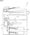
- the multifunction peripheral 100 of this embodiment is equipped with a document feeder unit 2a and an image reader unit 2b disposed on an upper part.
- the document feeder unit 2a transports document sheets to a reading position automatically and successively.
- the image reader unit 2b reads the transported document sheet or a document placed on a contact glass so as to generate image data.
- the multifunction peripheral 100 includes inside a paper sheet feeder unit 3a, a transport unit 3b, an image forming unit 3c, a fixing unit 3d, a discharge transport unit 3e, a double-sided transport unit 3f, and the like.
- the paper sheet feeder unit 3a feeds paper sheets one by one to the transport unit 3b.
- the transport unit 3b transports the paper sheet to a discharge tray 31.
- the image forming unit 3c forms a toner image based on image data.
- the fixing unit 3d fixes the toner image transferred onto the paper sheet.
- the discharge transport unit 3e discharges the paper sheet after the toner image is fixed (printed paper sheet) onto the discharge tray 31.
- the discharge transport unit 3e transports the paper sheet in the direction toward the double-sided transport unit 3f when performing double-sided printing.
- the double-sided transport unit 3f transports the paper sheet whose one side is printed to an upper stream side of the image forming unit 3c.
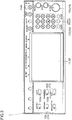
- the operation panel 1 is disposed on the upper front of the multifunction peripheral 100 (see FIG. 1 ). Further, as illustrated in FIG. 2 , the operation panel 1 includes a display unit 11, a touch panel unit 12 (corresponding to the operation input unit), various hardware keys 13 (corresponding to the operation input unit). The operation panel 1 includes, as the hardware keys 13, a start key 131 for instructing to start a process such as a copying process and a ten-key unit 132 for inputting numbers.
- the display unit 11 is a liquid crystal display panel. Note that the display unit 11 may be other type of panel such as an organic EL panel.
- the display unit 11 displays a menu for performing setting of the multifunction peripheral 100 or a screen in which keys are arranged, and an image. The user designates a key displayed on the display unit 11 so as to input various settings of the multifunction peripheral 100. In addition, the display unit 11 displays various images and screens such as a message of a state of the multifunction peripheral 100.
- the touch panel unit 12 is disposed on (an upper surface of) the display unit 11.
- the touch panel unit 12 is disposed for detecting coordinates at which the user touches. By comparing a display position of a key with the touched position, the key designated by the user is specified, and the user's input is accepted.
- the touch panel unit 12 of this embodiment can detect a plurality of touched points. For instance, a capacitive touch panel is adopted.
- the operation panel 1 includes a plurality of function selection keys 133.
- the user presses one of the function selection keys 133 so as to select a function to use of the multifunction peripheral 100.
- the function selection keys 133 include a copying key 133a to be pressed when copying function is used, a transmission key 133b to be pressed when transmitting image data read by the image reader unit 2b to a computer 200 or a FAX apparatus 300. Further, when one of the function selection keys 133 is pressed, the display unit 11 selects a setting item concerning the selected function (pressed function selection key 133) and displays a setting screen for determining a setting value of the selected setting item.
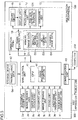
- a main control unit 4 is disposed in a main body of the multifunction peripheral 100.
- the main control unit 4 is connected to the operation panel 1, the document feeder unit 2a, the image reader unit 2b, the paper sheet feeder unit 3a, the transport unit 3b, the image forming unit 3c, the fixing unit 3d, the discharge transport unit 3e, and the like, so as to control operations of these units.
- the main control unit 4 includes a controlling element such as a CPU 41 and a circuit.
- the CPU 41 performs calculation and the like based on a control program and control data stored in a storage device 42, so as to control individual units of the multifunction peripheral 100.
- the storage device 42 is connected to the main control unit 4.
- the storage device 42 is a combination of nonvolatile and volatile storage devices including a ROM, a RAM, an HDD, and the like.
- the storage device 42 can store a control program of the multifunction peripheral 100 and various data such as control data, setting data, and image data.
- the main control unit 4 is connected to a communication unit 43.
- the communication unit 43 is connected to the computer 200 and the FAX apparatus 300 (only one of each is illustrated in FIG. 3 for convenience sake) via a network, a public line, or the like.
- the main control unit 4 can transmit data including the image data via the communication unit 43 to the external computer 200 or the FAX apparatus 300 on the other party (a scanner function and a FAX transmission function).
- the main control unit 4 can also perform printing based on the image data transmitted from the external computer 200 or the FAX apparatus 300 on the other party and is input to the multifunction peripheral 100 (a printer function and a FAX reception function).
- the main control unit 4 includes an image processing portion 44 for performing image processing on the image data obtained by reading a document or obtained by reception via the communication unit 43.
- the image data processed by the image processing portion 44 is used for printing or transmission, or is stored in the storage device 42.
- the display unit 11 can display an image for checking whether or not settings are appropriate before executing the printing or transmission job, which is a finished image 7 on which the setting value set on the operation panel 1 is reflected.
- the image processing portion 44 generates the image data necessary for the display unit 11 to display this finished image 7.
- the main control unit 4 recognizes an input performed by the operation panel 1 and controls the multifunction peripheral 100 to perform the job such as copying, document reading, or transmission in accordance with the user's setting.
- the operation panel 1 of this embodiment includes a panel control unit 10, the display unit 11, the touch panel unit 12, the hardware keys 13 (for example, the ten-key unit 132 and the start key 131), a memory 14 (corresponding to the storage unit), a driver circuit 15, and the like.
- the panel control unit 10 includes a CPU, an IC, and the like.
- the panel control unit 10 controls display of the display unit 11.
- the main control unit 4 transmits data necessary for display to the panel control unit 10.
- the panel control unit 10 referred to the storage content of the memory 14 for storing data such as image data D1 for display, a program for display and operation control, and the like based on an instruction from the main control unit 4. Further, the panel control unit 10 gives an instruction of display content to the driver circuit 15 that actually controls display of the display unit 11.
- the panel control unit 10 receives an output of the touch panel unit 12 so as to detect and recognize the touched position (coordinates).
- the touch panel unit 12 is provided with a position detection portion 121.
- the position detection portion 121 is an IC for detecting a touched position (coordinates of a touched point).
- the panel control unit 10 recognizes the touched position based on an output of the touch panel unit 12 (position detection portion 121). Further, the panel control unit 10 compares the touched position with image data of the screen displayed on the display unit 11 when the position is touched, so as to recognize a key or a button displayed at the touched position.
- the data such as a table indicating correspondence between an output of the touch panel unit 12 and the position (coordinates) is stored in the memory 14.
- the memory 14 includes a ROM and a RAM. In this way, the panel control unit 10 can recognize the key operated by the user.
- the user can select a function to be used such as the copying function or the transmission function using the function selection key 133.
- the multifunction peripheral 100 also has other functions such as the printer function for printing based on image data and the setting data transmitted from the computer 200, and a box function for accumulating image data obtained by reading so as to reuse the image data.
- the copying function is a function of reading a document and printing based on the read image data so as to copy the document. Further, a plurality of setting items are prepared for the copying function. Note that a plurality of setting items are also used for other functions such as the transmission function.
- the panel control unit 10 controls the display unit 11 to display a selection screen 5 for selecting the setting item about the copying function.
- the panel control unit 10 controls the display unit 11 to display an quick setup tab 61, a org/paper/finishing tab 62, an image quality tab 63, a layout/edit tab 64, an advanced setup tab 65, and a set value comparison tab 66 in various selection screens 5.
- the setting items are classified into one or more categories (tabs).
- the panel control unit 10 controls the display unit 11 to display the selection screen 5 for selecting a setting item associated with the touched tab (a setting item classified to belong a category of the touched tab in advance).
- the selection screen 5 a list of selection keys for selecting a setting item is displayed.
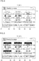
- FIG. 4 and FIG. 5 illustrate an example of the selection screen 5 that is displayed when a display position of the layout/edit tab 64 is touched.
- keys for selecting setting items about a layout of pages in copying and editing of print content are arranged.
- a plurality of setting item selection keys such as a zoom key K1, a combine key K2, a margin/centering key K3, a booklet key K4, a duplex key K5, a front cover key K6, a page number insertion key K7, a memo page key K8, and a border erase key K9.
- the selection screen 5 is displayed in which keys corresponding to the setting item that is selected by the user in advance or is initially set as being frequently set based on experience are arranged.
- the selection screen 5 for selecting a setting item about the document or the paper sheet such as a document size, the paper sheet size, directions of the document and the paper sheet, a paper feed source, and the like.
- the image quality tab 63 is touched, the selection screen 5 for selecting a setting item about image quality such as density of a printed matter is displayed.
- the selection screen 5 for selecting a setting item that does not belong to any one of the tabs 61 to 65 is displayed. Note that illustration and description of the selection screens 5 corresponding to the tabs 61 to 63 and 65 are omitted.
- the panel control unit 10 controls the display unit 11 to display a setting value setting screen (not shown) for setting the setting value of the selected setting item.
- a setting value setting screen (not shown) for setting the setting value of the selected setting item.
- the image data D1 (see FIG. 3 ) necessary for displaying the selection screen 5 or the setting value setting screen is stored in the memory 14 (see FIG. 3 ).
- the panel control unit 10 uses the image data D1 in the memory 14 so as to control the display unit 11 to display the selection screen 5 corresponding to an operation of the tab and controls the display unit 11 to display the setting value setting screen corresponding to an operation of the setting item selection key.
- the setting item corresponding to the setting item can be selected.
- a zoom setting screen displayed when the zoom key K1 is operated a zoom magnification in copying (a size ratio of the copy to the document) can be set as the setting value.
- a combine setting screen displayed when the combine key K2 is operated it is possible to set whether or not to combine a plurality of pages into one page of the printed matter, and how many pages are to be combined, as the setting values.
- the setting screen displayed when the margin/centering key K3 is operated it is possible to set margins in one page of the printed matter and whether or not to perform centering as the setting values.
- a booklet setting screen displayed when the booklet key K4 is operated it is possible to set whether or not to perform booklet print, and the like, as the setting values.
- a double-sided setting screen displayed when the duplex key K5 is operated it is possible to set whether or not to perform the double-sided printing as the setting values.
- the front cover setting screen displayed when the front cover key K6 is operated it is possible to set whether or not to insert a front cover such as blank paper as a front page of one copy, and the like, as the setting values.
- a number setting screen displayed when the page number insertion key K7 is operated it is possible to set whether or not to add page numbers in the printed matter, which position the page numbers are added at, and the like, as the setting values.
- a memo setting screen displayed when the memo page key K8 is operated it is possible to set whether or not to reduce a document size so as to generate a margin for memo, and the like, as the setting values.
- a border erase setting screen displayed when the border erase key K9 is operated it is possible to set whether or not to have a blank margin of a predetermined length from an edge of the printed matter, a value of the predetermined length, and the like, as the setting values.
- the panel control unit 10 controls the display unit 11 to display a plurality of tabs. Further, when the touch panel unit 12 detects a touch of the display position of the tab, the panel control unit 10 controls the display unit 11 to display the setting item selection key classified with reference to the tab. Then, the panel control unit 10 recognizes the selected setting item based on an output of the touch panel unit 12 and an output of the hardware key 13, recognizes the operation of setting the setting value on the setting screen of the selected setting item, and accepted the same.
- the panel control unit 10 controls the display unit 11 to display a pattern or an icon indicating the setting item to accompany the setting item selection key corresponding to the setting item of which the setting value is not set by the user.
- the panel control unit 10 controls the display unit 11 to display the set setting value of the setting item of which the setting value is set by the user, instead of the pattern or the icon.
- a display form of a display field of the setting value is changed. For instance, the display form is changed by black and white reversal or display color change of the setting item selection key.
- FIG. 4 and FIG. 5 illustrate an example in which the user has set setting values in four setting items.
- setting values of four setting items are changed from default setting values.
- the setting value "Auto” is set for the zoom setting item (the default value is "100%, i.e., actual size")
- the setting value "2 in 1” is set for the combine setting item (the default value is “not combine")
- the setting value "Centering” is set for the margin/centering setting item (the default value is “not centering")
- the setting value "put page number in the bottom middle in the form of - # -” is set for the page number insertion setting item (the default value is "don't put page numbers”).
- multifunction peripheral 100 of this embodiment many (for example, total a hundred or more) selectable or settable setting items are prepared for using the individual functions.
- the default setting value is "not use (not execute)" the setting item (function).
- the setting item such as the zoom magnification or the density, which requires to set a specific value instead of simply setting Yes or No (instead of simply setting to use or not the setting item or function)
- the default setting value is a value that is regarded to be used most frequently (for example, "actual size" for the zoom setting item).
- data indicating default setting values of the individual setting items (default setting value data D2) is stored in the memory 14 (see FIG. 3 ).
- the memory 14 also stores the set setting values. Alternatively, they may be stored in the storage device 42.
- the main control unit 4 executes the job using the default setting value.
- the zoom magnification is set to the actual size
- the density is set to the standard density. Therefore, when the document is set and the start key 131 is pressed without changing the setting values, the multifunction peripheral 100 of this embodiment performs copying with the standard density in the actual size.
- the zoom setting value is "Auto”
- the combine setting value is “2 in 1”
- the margin/centering setting value is “Centering”
- the page number insertion setting value is "put page number in the bottom middle in the form of - # -"
- the operation panel 1 (the display unit 11, the touch panel unit 12, the hardware key 13, and the like) accepts the user's setting input of the setting value. Then, the operation panel 1 (display unit 11) displays the finished image 7 on which the set setting value is reflected (image indicating an example of the execution result of the job). By viewing this finished image 7, the user can check whether or not there is an omission of setting and whether or not the selected setting item and the set setting value match with the user's intention. In this way, it is possible to prevent an omission of setting a setting error, and to prevent that a wasteful job is executed with content that the user does not intend.
- the operation panel 1 can display the default setting image 8 on which the default setting value is reflected for checking a result when the job is executed based on the default setting value by satisfying a predetermined condition or by a simple operation (by a single operation), following the finished image 7 (or instead of the finished image 7).
- the user can visually compare the finished image 7 with the default setting image 8 so as check how the result obtained by setting the setting value is different from that based on the default value.
- the panel control unit 10 controls the display unit 11 to display the finished image 7.
- the panel control unit 10 may control the display unit 11 to display the finished image 7 when the job execution is instructed by pressing the start key 131 or the like.
- the display unit 11 displays an all setting value image 71 on which all the setting values set by the user as a first stage of the finished image 7.
- the finished image 7 (all setting value image 71) can be displayed by a simple operation of touching the set value comparison tab 66 disposed in each selection screen 5.
- the panel control unit 10 controls the display unit 11 to display the all setting value image 71 on which all the setting values set by the user are reflected as the first stage of the finished image 7.
- the setting value changed by the user from the default value (setting value set by the user) is stored as set content data D3.
- the finished image 7 may be displayed with reference to (by using) the image data obtained by reading one or more pages of document sheets.
- the document feeder unit 2a transports one or more document sheets so that the image reader unit 2b reads the one or more document sheets.
- the image reader unit 2b reads a document placed on a place-reading contact glass 21 (see FIG. 1 ).
- the document read for displaying the finished image 7 may be put back to the original set position before the job is executed. Alternately, it is possible to configure to execute the job by using the image data obtained by reading for displaying the finished image 7 so that it is not necessary to put back the document.
- the storage device 42 or the memory 14 stores the image data of the one or more document sheets obtained by reading. Then, the panel control unit 10 (or the image processing portion 44) performs image processing on the image data obtained by reading corresponding to all the set setting values (or the default setting value for the setting item that is not set), and performs image processing for matching the number of dots with that of a display area of the finished image 7 (reducing process), so as to generate a finished image data D4 for displaying the all setting value image 71.
- image data prepared in advance may be used as image data to be a base of displaying the finished image 7.
- image data to be a base of displaying the finished image 7 is stored in advance in the memory 14 or the storage device 42.
- the panel control unit 10 When using image data prepared in advance, the panel control unit 10 (or the image processing portion 44) reads out the image data prepared in advance, and performs image processing on the image data prepared in advance corresponding to all the set setting values (or the default setting value for the setting item that is not set), so as to generate the finished image data D4 for displaying the all setting value image 71. In addition, the image processing for matching the number of dots with that of the display area of the finished image 7 is also performed as necessary.
- the panel control unit 10 controls the display unit 11 to display the all setting value image 71 based on the finished image data D4 for displaying the generated all setting value image 71.
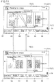
- the all setting value image 71 illustrated as an example in the upper side in FIG. 6 indicates a state where the setting values "2 in 1", “Page number insertion", “Centering”, and "Automatic zoom” are reflected.
- a character string indicating the set setting value or the setting item is added to the all setting value image 71. In this way, it is easy to understand which setting value and setting item are set, and which setting value and setting item are reflected on the finished image 7.
- the diagram on the upper side of FIG. 6 indicates an example in which the panel control unit 10 controls the display unit to display character strings such as "2 in 1" corresponding to the combine printing setting value, "Page” corresponding to the page number insertion, "Centering” corresponding to the margin/centering, and "Auto” corresponding to the zoom setting value.
- the displayed character string and the display position of the character string are determined in advance so that the character string is displayed at a part having a large influence when the setting value is set (for easy understanding).
- the panel control unit 10 controls the display unit 11 to display the default setting image 8 instead of (successively to) the all setting value image 71.
- the display unit 11 alternately displays the finished image 7 for checking a result when the job is executed based on all the set setting values reflected (the all setting value image 71 on which all the set setting values are reflected) and the default setting image 8 on which the default setting values are reflected for checking a result when the job is executed based on the default setting values, by switching between them.
- the user can visually compare the finished image 7 with the default setting image 8.
- the user can easily check a difference between the case where the setting value of the selected setting item is set and the case where the same is not set. Specifically, when the first switching condition is satisfied, or when the operation input unit (the touch panel unit 12, the hardware key 13, and the like) accepts the first switching operation, the display unit 11 switches the display from the all setting value image 71 to the default setting image 8 in the case where the all setting value image 71 is displayed, and switches the display from the default setting image 8 to the all setting value image 71 in the case where the default setting image 8 is displayed. In this way, the finished image 7 and the default setting image 8 are displayed alternately by switching (so that a different part is emphasized in an animated manner).
- the user can visually compare the finished image 7 with the default setting image 8 so as to check a difference between a result obtained by setting the setting value and a result obtained by the default setting.
- the user can visually compare the finished image 7 with the default setting image 8 repeatedly.
- the finished image 7 and the default setting image 8 can be largely displayed so that the user can view them without difficulty.
- the user can visually compare the result of the default setting with the result of the set setting value in one screen. Therefore, the user can easily understand how the process is performed by the selected setting item and the setting value (contents of the setting item and the setting value).
- the default setting image 8 may be based on image data of the document that is actually read. In this case, based on the image data of one or more document sheets obtained by reading for displaying the finished image 7 (the all setting value image 71), the panel control unit 10 (or the image processing portion 44) performs image processing using the default setting values for all the setting items and performs image processing for matching the number of dots with that of the display area of the finished image 7 (reducing process), so as to generate image data for displaying the default setting image 8. On the other hand, it is possible to display the default setting image 8 by using the image data for displaying the default setting image prepared in advance. In this case, the same image is displayed every time as the default setting image 8.
- the predetermined first switching condition can be determined appropriately.
- the first switching condition is that a predetermined period of time (for example, approximately 5 to 10 seconds) has passed after the input to the operation panel 1 (touch of the touch panel unit 12, the hardware key 13, or the function selection key 133) is vanished (for example, the panel control unit 10 counts the time).
- a predetermined first switching operation can be determined appropriately.
- the first switching operation is a long press to the touch panel unit 12 (continuous touch at the same position for a predetermined period of time such as approximately one to a few seconds).
- the first switching operation may be other gesture operations such as a flick operation.
- the panel control unit 10 controls the display unit 11 to display the all setting value image 71 that was displayed before, switching from the default setting image 8.
- the two images can be easily compared with each other.
- the operation panel 1 of this embodiment displays the all setting value image 71 (indicating a job execution result).
- the touch panel unit 12 accepts a predetermined separating operation in a state of displaying the finished image 7 on which the plurality of setting values are reflected (for example, the all setting value image 71 or a combination setting value image 73 described later)
- the panel control unit 10 controls the display unit 11 to display a separate setting value image 72.
- the separate setting value image 72 is an image on which only one setting value is reflected and the default setting value is used or other setting items.
- the panel control unit 10 controls to display a plurality of separate setting value images 72.
- the predetermined separating operation can be determined appropriately.
- the touch panel unit 12 panel control unit 10) accepts a gesture operation of pinch out (operation of touching two points and then extending a distance between the two points) in an area outside the finished image 7 on the touch panel unit 12 as the separating operation.
- the panel control unit 10 controls the display unit 11 to display a plurality of finished images 7 (separate setting value images 72) on which only one setting value is reflected for each type of the set setting value switching from the all setting value image 71.
- the storage device 42 or the memory 14 stores the image data of the one or more document sheets obtained by reading. Then, the panel control unit 10 (or the image processing portion 44) performs image processing on the image data obtained by reading in which only one setting value is reflected for each set setting value (or the default setting value is used for the setting item that is not set), and the image processing for matching the number of dots with that of the display area of the finished image 7. Then, the panel control unit 10 generates a plurality of finished image data D4 for displaying the separate setting value images 72 in the same number as the setting values set by the user.
- fixed image data prepared in advance may be used as the image data to be a base of displaying the finished image 7.
- the image data to be a base of displaying the finished image 7 is stored in advance in the memory 14 or the storage device 42.
- the panel control unit 10 or the image processing portion 44
- the panel control unit 10 or the image processing portion 44
- the panel control unit 10 or the image processing portion 44
- the panel control unit 10 or the image processing portion 44
- the image processing for matching the number of dots with that of the display area of the finished image 7 is also performed as necessary.
- the panel control unit 10 controls the display unit 11 to display the separate setting value images 72 one by one in an overlaid manner on the display unit 11 based on the generated finished image data D4 for displaying the plurality of separate setting value images 72.
- the panel control unit 10 controls the display unit 11 to display the four separate setting value images 72 as illustrated in FIG. 7 .
- the leftmost separate setting value image 72 indicates the finished image 7 in a state where only the setting value of "Auto (automatic zoom)” is set.
- the second separate setting value image 72 from the left indicates the finished image 7 in a state where only the setting value of "Centering (margin/centering process)" is set.
- the third separate setting value image 72 from the left indicates the finished image 7 in a state where only the setting value of "2 in 1" is set.
- the rightmost separate setting value image 72 indicates the finished image 7 in a state where only the setting value of "Bottom middle in the form of - # -" is set. Note that the direction of the document is rotated by 90 degrees in the 2 in 1 print. Therefore, in the separate setting value images 72 other than the setting value of 2 in 1, the direction of the document is different from that in the all setting value image 71.
- the panel control unit 10 controls the display unit 11 to display the all setting value image 71 as the finished image 7 switching from the separate setting value image 72.
- the predetermined returning operation can be determined appropriately.
- the touch panel unit 12 (panel control unit 10) of this embodiment accepts a gesture operation of pinch in (operation of touching two points and then narrowing a distance between the two points) in an area outside all the separate setting value images 72 on the touch panel unit 12 as the returning operation.
- the state of the diagram on the lower side in FIG. 7 is switched to the state illustrated in the upper side in FIG. 7 (display state of the all setting value image 71).
- the panel control unit 10 controls the display unit 11 to stop the display of the separate setting value image 72 and to display the all setting value image 71 instead.
- the image data for displaying the all setting value image 71 can be the one generated before.
- the display unit 11 displays a plurality of separate setting value images 72 for each set setting value as the finished image 7, on which only one setting value is reflected and the default setting values are used for other setting items.
- the display unit 11 displays the all setting value image 71 instead of the separate setting value images 72. In this way, the user can check a difference from the default setting image 8 for each setting value (setting item). Therefore, the user can check how the obtained result is different by setting one setting item and can easily understand content of the process performed base on the selected setting item and the set setting value.
- a size of the display unit 11 is limited.
- the panel control unit 10 controls the display unit 11 to display so that the separate setting value images 72 are overlapped partially. Therefore, there is a case where it is difficult to visually check the separate setting value image 72 on a lower layer.
- the panel control unit 10 controls the display unit 11 to display the selected separate setting value image 72 on the top layer.
- the operation of selecting one of the overlapped separate setting value images 72 can be determined appropriately.
- the separate setting value image 72 is assigned with a tab having a setting item name of the setting value that is reflected. In this way, it is easy to recognize which setting item and setting value are reflected on the separate setting value image 72.
- the operation of touching the display position of the tab may be regarded as the selecting operation.
- an operation of touching an area in one of the overlapped separate setting value images 72 and releasing before being determined to be the long press may be regarded as the operation of selecting the separate setting value image 72.
- FIG. 8 illustrates and example of selecting the separate setting value image 72 corresponding to the setting item of the page number insertion among the plurality of separate setting value images 72 (setting value of "Bottom middle in the form of - # -").
- the panel control unit 10 controls the display unit 11 to display the separate setting value image 72 corresponding to the setting item of the page number insertion on the top layer (the frontmost layer or the uppermost layer). In this way, it is possible to arbitrarily switch the separate setting value image 72 to be displayed on the top layer.
- the panel control unit 10 controls to display the default setting image 8 in a display area of the separate setting value image 72.
- the default setting image 8 is the same as that described above.
- the predetermined second switching condition can be determined appropriately.
- the second switching condition is that a predetermined period of time (for example, approximately 5 to 10 seconds) has passed after the input to the operation panel 1 (touch of the touch panel unit 12, the hardware key 13, or the function selection key 133) is vanished.
- the second switching condition may be the same as the first switching condition.
- the predetermined second switching operation can be determined appropriately.
- the long press to the panel control unit 10 touch panel unit 12
- a predetermined period of time such as approximately one to a few seconds
- the second switching operation may be other gesture operations such as a flick operation.
- the panel control unit 10 controls the display unit 11 to display the separate setting value image 72 that was displayed before, switching from the default setting image 8. In this way, it is possible to switch between the default setting image 8 and the separate setting value image 72 so as to compare them.
- the display unit 11 switches the display of one or more separate setting value images 72 to the default setting image 8 in the state of displaying the separate setting value images 72.
- the display unit 11 switches the display of the default setting image 8 to the separate setting value images 72 that were displayed before.
- the finished image 7 separate setting value images 72
- the default setting image 8 is alternately switched and displayed.
- the user can compare the finished image 7 and the default setting image 8 repeatedly so as to check the difference between them. Therefore, the user can correctly grasp a difference between the default setting value and the one set setting value when the job is executed.
- the panel control unit 10 may perform the display switching between the separate setting value image 72 and the default setting image 8 only on a part or one of the plurality of separate setting value images 72.
- the panel control unit 10 may control the display unit 11 to perform the display switching between the separate setting value image 72 and the default setting image 8 in the display area of the separate setting value image 72 of the top (frontmost) layer.
- the panel control unit 10 may perform the display switching in the display area of the separate setting value image 72 on which the second switching operation (long press) is performed as illustrated in FIG. 9 .
- the display unit 11 displays the selected separate setting value image 72 on the frontmost layer and performs the display switching between the default setting image 8 and the separate setting value image 72 only for the separate setting value image 72 on the frontmost layer.
- the finished image 7 separate setting value image 72
- the user can visually compare the case of the default setting value with the case of setting the setting value for the specific setting value (check a difference between the default value and a changed setting value).
- the panel control unit 10 may control to perform the display switching between the separate setting value image 72 and the default setting image 8 in the display area of the all the separate setting value images 72.
- the image forming apparatus (multifunction peripheral 100) according to the embodiment includes the display input device (operation panel 1) described above. In this way, it is possible to provide the image forming apparatus in which the user can visually compare the finished image 7 with the default setting image 8 so as to easily check a difference between the case where the user sets the setting value of the selected setting item and the case where the user does not set the same. Therefore, it is possible to provide the image forming apparatus in which setting is easily understood.
- the separate setting value image 72 can be displayed for each setting value set by the user.
- the finished image 7 with specific combined setting values among the plurality of set setting values can be displayed instead of one setting value unit, it is easy to determine whether or not the set setting value is necessary.
- the user can easily determine whether or not the setting is necessary.
- the panel control unit 10 controls the display unit 11 to display the combination setting value image 73 switching from the selected finished images 7 (separate setting value images 72).
- the combination setting value image 73 is an image on which a combination of setting values corresponding to the selected plurality of finished images 7 is reflected.
- the default setting values are used for the combination setting value image 73. In this way, the user can view a display of the finished image 7 (combination setting value image 73) on which the combination of the selected setting values is reflected. Therefore, by checking the combination setting value image 73, the user can determine whether or not a part of the set setting values are necessary.
- the predetermined combining operation can be determined appropriately.
- the panel control unit 10 (touch panel unit 12) of this embodiment accepts a gesture operation as the combining operation, in which positions in a display area of the plurality of finished images 7 are touched, and a distance between the touched positions is narrowed (operation in which a plurality of points in the display area of the plurality of finished images 7 are touched, and then a distance between two of the touched points is narrowed).
- the operation input unit includes the touch panel unit 12 disposed on the display unit 11, and the touch panel unit 12 accepts various gesture operations such as the combining operation.
- a display on the display unit 11 of the display input device (operation panel 1) can be operated by a simple operation, and it is possible to easily perform switching between the finished image 7 and the default setting image 8, separation of the finished image 7, and combination of the same.
- the combination setting value image 73 displayed by the combining operation is also provided with tabs having the setting item names (or the setting value names) of the setting values reflecting on the image.
- the finished image 7 other than the all setting value image 71 is provided with the tabs having one or more setting item names or the setting values reflecting on the image.
- the storage device 42 or the memory 14 stores image data of one or more document sheets obtained by reading. Then, the panel control unit 10 (or the image processing portion 44) performs image processing on the image data obtained by reading for reflecting the combined setting values (or the default setting value is used for the setting item that is not set), and the image processing for matching the number of dots with that of the display area of the finished image 7. Then, the panel control unit 10 generates the finished image data D4 for displaying the combination setting value image 73.
- fixed image data prepared in advance may be used as the image data to be a base of displaying the finished image 7.
- the image data to be a base of displaying the finished image 7 is stored in advance in the memory 14 or the storage device 42.
- the panel control unit 10 (image processing portion 44) generates the finished image data D4 for displaying the combination setting value image 73 indicated by the result of the setting values for which the user instructs to combine.
- the image processing for matching the number of dots with that of the display area of the combination setting value image 73 is also performed as necessary.
- the panel control unit 10 controls the display unit 11 to display the combination setting value image 73 based on the generated finished image data D4.
- the diagram on the upper side of FIG. 10 illustrates the combining operation for combining the setting value "2 in 1" and the setting value "Bottom middle in the form of - # -".
- the panel control unit 10 controls the display unit 11 to display the combination setting value image 73 indicting a result of executing the job with the setting values of "2 in 1" and "Bottom middle in the form of - # -".
- the panel control unit 10 may control the display unit 11 to display the combination setting value image 73 on the top layer (frontmost layer).
- the leftmost finished image 7 illustrates the combination setting value image 73 in which the setting values "2 in 1" and "Bottom middle in the form of - # -" are combined.
- the second finished image 7 from the left illustrates the separate setting value image 72 in which only the setting value "automatic zoom (auto)” is set.
- the third separate setting value image 72 from the left illustrates the separate setting value image 72 in which only the setting value "margin/centering (Centering)" is set.
- the panel control unit 10 controls the display unit 11 to display the separate setting value image 72 for each setting value reflecting on the combination setting value image 73 switching from the combination setting value image 73.
- FIG. 10 illustrates the combination setting value image 73 on which the two setting items (setting values) are reflected, but the panel control unit 10 can control to display the combination setting value image 73 on which three or more setting items (setting values) are reflected.
- the panel control unit 10 controls the display unit 11 to display the combination setting value image 73 on which three or more setting values are reflected.
- the panel control unit 10 controls the display unit 11 to stop the display of the plurality of finished images 7 (combination setting value image 73 and separate setting value image 72), and controls to display the all setting value image 71 instead.
- the image data for displaying the all setting value image 71 can be the one generated before.
- the panel control unit 10 displays the selected finished image 7 (combination setting value image 73 or the separate setting value image 72) on the frontmost layer.
- the panel control unit 10 controls to display the default setting image 8 in the display area of the combination setting value image 73.
- the default setting image 8 is the same as that described above.
- the predetermined third switching condition can be determined appropriately.
- the third switching condition is that a predetermined period of time (for example, approximately 5 to 10 seconds) has passed after the input to the operation panel 1 (touch of the touch panel unit 12, the hardware key 13, or the function selection key 133) is vanished.
- the third switching condition may be the same as the first switching condition or the second switching condition.
- the predetermined third switching operation can be determined appropriately.
- the third switching operation is a long press to the touch panel unit 12 (continuous touch at the same position for a predetermined period of time such as approximately one to a few seconds).
- the panel control unit 10 controls the display unit 11 to display the combination setting value image 73 that was displayed before, switching from the default setting image 8.
- the display unit 11 switches the display from the combination setting value image 73 to the default setting image 8 in the state where the combination setting value image 73 is displayed, and switches the display from the default setting image 8 to the combination setting value image 73 that was displayed before in the state where the default setting image 8 is displayed.
- the finished image 7 (combination setting value image 73) on which the selected setting value is reflected and the default setting image 8 among the plurality of set setting values are alternately switched and displayed.
- the different part is displayed in an emphasized manner. Therefore, the user can compare the finished image 7 and the default setting image 8 repeatedly so as to check the difference between them. Therefore, the user can correctly determine whether or not a desired result will be obtained by the combination of the plurality of setting values.
- the panel control unit 10 may perform the display switching between the combination setting value image 73 and the default setting image 8 on a part or only one of the plurality of the displayed finished images 7 (the combination setting value image 73 and the separate setting value image 72). In this case, the panel control unit 10 may perform the display switching between the combination setting value image 73 and the default setting image 8 only in the display area of the combination setting value image 73. In addition, the panel control unit 10 may perform the display switching on the combination setting value image 73 on which the third switching operation (long press) is performed as illustrated in FIG. 9 . In addition, on the contrary, the panel control unit 10 may perform the display switching between the separate setting value image 72 and the default setting image 8 in the display area of all the combination setting value images 73.
- the panel control unit 10 controls to display a canceling image 74 for performing an operation for canceling the setting value (for resetting to the default value) in the screen of the display unit 11.
- the canceling image 74 is a trash box image, for example.
- the canceling image 74 can be determined appropriately (for example, may be a mark " ⁇ ").
- the touch panel unit 12 accepts an operation for canceling the setting value set by the user and restoring the default setting value.
- This operation can be determined appropriately.
- the touch panel unit 12 (panel control unit 10) accepts an operation performed on the canceling image 74 after selecting one of the finished images 7 (the all setting value image 71, the separate setting value image 72, and the combination setting value image 73) as the operation of canceling the setting value corresponding to the selected finished image 7 and restoring the default setting value.
- the touch panel unit 12 panel control unit 10 accepts an operation performed on the canceling image 74 after selecting one of the finished images 7 (the all setting value image 71, the separate setting value image 72, and the combination setting value image 73) as the operation of canceling the setting value corresponding to the selected finished image 7 and restoring the default setting value.
- an operation of touching one of the finished images 7 (the all setting value image 71, the separate setting value image 72, and the combination setting value image 73), or the display position of the tab assigned to the finished image 7 is accepted as the operation of selecting the finished image 7.
- the touch panel unit 12 accepts an operation of moving the touched position to the canceling image 74 while keeping the touching state without releasing a finger (drag operation) as the operation for canceling the setting value.
- FIG. 12 illustrates an example in which the finished image 7 (separate setting value image 72) on which the setting value "Centering” is reflected is selected and the drag operation is performed so as to cancel the setting value "Centering” (to restore the default value "not centering”). In this way, without displaying again the setting screen of the setting value to be canceled, it is possible to restore the default setting value.
- the panel control unit 10 controls the memory 14 to update the set content data D3. Specifically, the panel control unit 10 updates the set content data D3 in the memory 14 to be data indicating that the canceled setting value is not set. In this way, the job is executed without reflecting the canceled setting value. For instance, in the example of FIG. 12 , the margin/centering process is not performed when the copying job is executed.
- the present disclosure can be used for a display input device or an image forming apparatus, which includes a display unit and a touch panel unit, and displays a preview image (finished image).
Landscapes
- Engineering & Computer Science (AREA)
- Human Computer Interaction (AREA)
- Multimedia (AREA)
- Signal Processing (AREA)
- Microelectronics & Electronic Packaging (AREA)
- Physics & Mathematics (AREA)
- General Physics & Mathematics (AREA)
- Facsimiles In General (AREA)
- Accessory Devices And Overall Control Thereof (AREA)
- User Interface Of Digital Computer (AREA)
Claims (12)
- Dispositif d'affichage et de saisie, comprenant :une unité de stockage (14) configurée pour stocker une valeur de réglage réglée et une valeur de réglage par défaut de chaque paramètre de réglage utilisée dans le cas où la valeur de réglage n'est pas réglée ;une unité de saisie d'opérations (12, 13) configurée pour accepter le réglage de la valeur de réglage ; etune unité d'affichage (11) configurée pour afficher un écran pour sélectionner le paramètre de réglage et pour régler la valeur de réglage du paramètre de réglage sélectionné, et pour afficher alternativement une image finie (7) pour vérifier un résultat lorsqu'un travail est exécuté en prenant en compte la valeur de réglage réglée, et une image de réglage par défaut (8) dans laquelle la valeur de réglage par défaut est prise en compte pour vérifier un résultat lorsque le travail est exécuté en prenant en compte la valeur de réglage par défaut, en commutant entre elles, caractérisé en ce quelorsque, dans un état d'affichage de l'image finale (7) dans laquelle une pluralité de valeurs de réglage réglées sont prises en compte, l'unité de saisie d'opérations (12, 13) accepte une opération de séparation prédéterminée, l'unité d'affichage (11) affiche une pluralité d'images aux valeurs de réglage distinctes (72) pour des valeurs de réglage réglées individuellement comme image finale (7), dans laquelle une seule valeur de réglage est prise en compte tout en utilisant la valeur de réglage par défaut pour d'autres paramètres de réglage, etlorsque l'unité de saisie d'opérations (12, 13) accepte une opération de retour prédéterminée dans un état d'affichage de l'image aux valeurs de réglage distinctes (72), l'unité d'affichage (11) affiche une image aux valeurs de réglage complètes (71) dans laquelle toutes les valeurs de réglage réglées sont prises en compte en tant qu'image finie (7), en commutant de l'image aux valeurs de réglage distinctes (72).
- Dispositif d'affichage et de saisie selon la revendication 1, dans lequel, lorsqu'une deuxième condition de commutation prédéterminée est satisfaite, ou lorsque l'unité de saisie d'opérations (12, 13) accepte une deuxième opération de commutation prédéterminée, l'unité d'affichage (11) commute de l'affichage d'une ou plusieurs des images aux valeurs de réglage distinctes (72) à l'image de réglage par défaut (8) dans un état d'affichage d'images aux valeurs de réglage distinctes (72), tandis que l'unité d'affichage (11) commute de l'affichage de l'image de réglage par défaut (8) à l'image aux valeurs de réglage distinctes (72) qui était affichée auparavant dans un état d'affichage de l'image de réglage par défaut (8) en commutant de l'image aux valeurs de réglage distinctes (72).
- Dispositif d'affichage et de saisie selon la revendication 2, dans lequell'unité d'affichage (11) affiche les images aux valeurs de réglage distinctes (72) en se chevauchant partiellement,lorsque l'unité de saisie d'opérations (12, 13) accepte une opération de sélection de l'une des images à valeurs de réglage distinctes superposées (72), l'unité d'affichage (11) affiche l'image à valeurs de réglage distinctes sélectionnée (72) sur un plan avant, etl'unité d'affichage (11) effectue la commutation d'affichage entre l'image de réglage par défaut (8) et l'image à valeurs de réglage distinctes (72) uniquement pour l'image à valeurs de réglage distinctes la plus en avant (72).
- Dispositif d'affichage et de saisie selon l'une quelconque des revendications 1 à 3, dans lequel lorsque l'unité de saisie d'opérations (12, 13) accepte une opération de combinaison prédéterminée après avoir sélectionné une pluralité d'images parmi les images finies affichées (7), l'unité d'affichage (11) affiche une image aux valeurs de réglage combinées (73) sur laquelle une combinaison d'une pluralité de valeurs de réglage correspondant aux images finies sélectionnées (7) est prise en compte comme image finie (7) tout en utilisant la valeur de réglage par défaut pour les autres paramètres de réglage, en commutant à partir des images finies sélectionnées (7).
- Dispositif d'affichage et de saisie selon la revendication 4, dans lequel lorsqu'une troisième condition de commutation prédéterminée est satisfaite, ou lorsque l'unité de saisie d'opérations (12, 13) accepte une troisième opération de commutation prédéterminée, l'unité d'affichage (11) commute de l'affichage de l'image aux valeurs de réglage combinées (73) à l'image de réglage par défaut (8) dans un état d'affichage de l'image aux valeurs de réglage combinées (73), tandis que dans un état d'affichage de l'image aux valeurs de réglage par défaut (8) l'unité d'affichage (11) commute de l'affichage de l'image de réglage par défaut (8) à l'image aux valeurs de réglage combinées (73) qui était affichée auparavant.
- Dispositif d'affichage et de saisie selon l'une quelconque des revendications 1 à 5, dans lequell'unité d'affichage (11) affiche une image d'annulation (74) pour l'opération d'annulation du réglage, etl'unité de saisie d'opérations (12, 13) accepte la sélection de l'image finie (7) et une opération sur l'image d'annulation (74) comme une opération d'annulation de la valeur de réglage réglée pour rétablir la valeur de réglage par défaut correspondant à l'image finie sélectionnée (7).
- Dispositif d'affichage et de saisie selon l'une quelconque des revendications 1 à 6, dans lequel
l'unité de saisie d'opérations (12, 13) comprend une unité à écran tactile disposée sur l'unité d'affichage (11), et l'unité à écran tactile accepte une opération par gestes. - Dispositif d'affichage et de saisie selon l'une quelconque des revendications 1 à 7, dans lequel l'unité d'affichage (11) affiche un onglet de comparaison des valeurs de réglage (66) pour sélectionner le paramètre de réglage dans chaque écran de sélection, et, lorsqu'une opération d'une position d'affichage de l'onglet de comparaison des valeurs de réglage (66) est effectuée, affiche une image à toutes les valeurs de réglage (71) sur laquelle toutes les valeurs de réglage réglées par l'utilisateur sont prises en compte comme première étape de l'image finie (73).
- Dispositif d'affichage et de saisie selon l'une des revendications 1 à 8, dans lequel l'unité d'affichage (11) affiche l'image finie (7) pourvue d'une série de caractères indiquant la valeur de réglage réglée et le paramètre de réglage.
- Dispositif d'affichage et de saisie selon l'une quelconque des revendications 1 à 5, dans lequel l'unité d'affichage (11) affiche l'image aux valeurs de réglage distinctes (72) pourvue d'un onglet ayant le nom du paramètre de réglage de la valeur de réglage prise en compte dans l'image.
- Appareil de formation d'images comprenant le dispositif d'affichage et de saisie selon l'une quelconque des revendications 1 à 10.
- Procédé de commande d'un dispositif d'affichage et de saisie, le procédé comprenant les étapes consistant àstocker une valeur de réglage réglée et une valeur de réglage par défaut de chaque paramètre de réglage utilisée dans le cas où la valeur de réglage n'est pas réglée ;afficher un écran pour sélectionner le paramètre de réglage et pour régler la valeur de réglage du paramètre sélectionné ;accepter le réglage de la valeur de réglage au moyen d'une unité de saisie d'opérations (12, 13) du dispositif d'affichage et de saisie ; etafficher alternativement une image finie (7) pour vérifier un résultat lorsqu'un travail est exécuté en prenant en compte la valeur de réglage réglée, et une image de réglage par défaut (8) dans laquelle est pris en compte la valeur de réglage par défaut, pour vérifier un résultat, lorsque le travail est exécuté en prenant en compte la valeur de réglage par défaut, en commutant de l'une à l'autre,caractérisé par le procédé comprenant en outre les étapes consistant à,afficher, par l'unité d'affichage (11), lorsque dans un état d'affichage de l'image finie (7) sur laquelle une pluralité de valeurs de réglage réglées sont prises en compte l'unité de saisie d'opérations (12, 13) accepte une opération de séparation prédéterminée, comme image finie (7) une pluralité d'images à valeurs de réglage distinctes (72) pour des valeurs de réglage réglées individuellement, etafficher, par l'unité d'affichage (11), lorsque dans un état d'affichage de l'image à valeurs de réglage distinctes (72) l'unité de saisie d'opérations (12, 13) accepte une opération de retour prédéterminée, l'image aux valeurs de réglage complètes (71) en commutant de l'image à valeurs de réglage distinctes (72),l'image à valeurs de réglage distinctes (72) étant une image dans laquelle une seule valeur de réglage est prise en compte tout en utilisant la valeur de réglage par défaut pour les autres éléments de réglage,l'image aux valeurs de réglage complètes (71) étant une image dans laquelle sont prises en compte toutes les valeurs de réglage réglées pour l'image finie (7).
Applications Claiming Priority (2)
| Application Number | Priority Date | Filing Date | Title |
|---|---|---|---|
| JP2013198878A JP5919239B2 (ja) | 2013-09-25 | 2013-09-25 | 表示入力装置、画像形成装置 |
| EP14184842.4A EP2853948B1 (fr) | 2013-09-25 | 2014-09-15 | Dispositif d'entrée d'affichage, appareil de formation d'image, procédé de commande pour dispositif d'entrée d'affichage |
Related Parent Applications (2)
| Application Number | Title | Priority Date | Filing Date |
|---|---|---|---|
| EP14184842.4A Division-Into EP2853948B1 (fr) | 2013-09-25 | 2014-09-15 | Dispositif d'entrée d'affichage, appareil de formation d'image, procédé de commande pour dispositif d'entrée d'affichage |
| EP14184842.4A Division EP2853948B1 (fr) | 2013-09-25 | 2014-09-15 | Dispositif d'entrée d'affichage, appareil de formation d'image, procédé de commande pour dispositif d'entrée d'affichage |
Publications (2)
| Publication Number | Publication Date |
|---|---|
| EP3521936A1 EP3521936A1 (fr) | 2019-08-07 |
| EP3521936B1 true EP3521936B1 (fr) | 2020-10-21 |
Family
ID=51539205
Family Applications (2)
| Application Number | Title | Priority Date | Filing Date |
|---|---|---|---|
| EP14184842.4A Not-in-force EP2853948B1 (fr) | 2013-09-25 | 2014-09-15 | Dispositif d'entrée d'affichage, appareil de formation d'image, procédé de commande pour dispositif d'entrée d'affichage |
| EP19156849.2A Not-in-force EP3521936B1 (fr) | 2013-09-25 | 2014-09-15 | Dispositif d'entrée d'affichage, appareil de formation d'images, procédé de commande pour dispositif d'entrée d'affichage |
Family Applications Before (1)
| Application Number | Title | Priority Date | Filing Date |
|---|---|---|---|
| EP14184842.4A Not-in-force EP2853948B1 (fr) | 2013-09-25 | 2014-09-15 | Dispositif d'entrée d'affichage, appareil de formation d'image, procédé de commande pour dispositif d'entrée d'affichage |
Country Status (4)
| Country | Link |
|---|---|
| US (1) | US9148534B2 (fr) |
| EP (2) | EP2853948B1 (fr) |
| JP (1) | JP5919239B2 (fr) |
| CN (1) | CN104469057B (fr) |
Families Citing this family (4)
| Publication number | Priority date | Publication date | Assignee | Title |
|---|---|---|---|---|
| JP6237138B2 (ja) * | 2013-11-12 | 2017-11-29 | 富士ゼロックス株式会社 | 情報処理装置、画像形成装置、および、プログラム |
| JP7091821B2 (ja) * | 2018-05-14 | 2022-06-28 | コニカミノルタ株式会社 | 画像処理装置及びプログラム |
| JP7173761B2 (ja) * | 2018-06-15 | 2022-11-16 | キヤノン株式会社 | 印刷システム、制御方法、サーバシステム |
| JP7247588B2 (ja) * | 2019-01-09 | 2023-03-29 | 京セラドキュメントソリューションズ株式会社 | 画像形成装置 |
Family Cites Families (11)
| Publication number | Priority date | Publication date | Assignee | Title |
|---|---|---|---|---|
| JP2004348405A (ja) * | 2003-05-22 | 2004-12-09 | Canon Finetech Inc | 情報処理装置及びプログラム |
| JP4403397B2 (ja) * | 2004-07-21 | 2010-01-27 | ソニー株式会社 | ユーザインタフェース提供装置 |
| JP2007074540A (ja) * | 2005-09-08 | 2007-03-22 | Canon Inc | 画像形成装置 |
| JP2007188054A (ja) * | 2005-12-15 | 2007-07-26 | Ricoh Co Ltd | 画像形成装置、プログラムおよび項目設定処理方法 |
| JP2007200304A (ja) | 2005-12-28 | 2007-08-09 | Brother Ind Ltd | 情報処理装置、情報処理方法およびプログラム |
| US7636040B2 (en) * | 2005-12-28 | 2009-12-22 | Brother Kogyo Kabushiki Kaisha | Information processing apparatus and information processing method |
| JP4704234B2 (ja) | 2006-02-20 | 2011-06-15 | 株式会社リコー | 画像形成装置、表示処理装置、表示処理方法および表示処理プログラム |
| JP4949771B2 (ja) * | 2006-08-11 | 2012-06-13 | 京セラミタ株式会社 | 表示制御プログラム |
| JP2008182436A (ja) * | 2007-01-24 | 2008-08-07 | Kyocera Mita Corp | 画像形成装置 |
| JP4922021B2 (ja) * | 2007-03-07 | 2012-04-25 | 株式会社リコー | 画像処理装置、プログラムおよびプレビュー画像表示方法 |
| JP5133371B2 (ja) | 2010-06-25 | 2013-01-30 | シャープ株式会社 | 画像形成装置 |
-
2013
- 2013-09-25 JP JP2013198878A patent/JP5919239B2/ja not_active Expired - Fee Related
-
2014
- 2014-09-12 US US14/485,120 patent/US9148534B2/en not_active Expired - Fee Related
- 2014-09-15 EP EP14184842.4A patent/EP2853948B1/fr not_active Not-in-force
- 2014-09-15 CN CN201410469555.0A patent/CN104469057B/zh not_active Expired - Fee Related
- 2014-09-15 EP EP19156849.2A patent/EP3521936B1/fr not_active Not-in-force
Non-Patent Citations (1)
| Title |
|---|
| None * |
Also Published As
| Publication number | Publication date |
|---|---|
| US9148534B2 (en) | 2015-09-29 |
| EP2853948B1 (fr) | 2019-03-20 |
| CN104469057A (zh) | 2015-03-25 |
| EP3521936A1 (fr) | 2019-08-07 |
| JP2015064791A (ja) | 2015-04-09 |
| EP2853948A1 (fr) | 2015-04-01 |
| CN104469057B (zh) | 2018-04-13 |
| JP5919239B2 (ja) | 2016-05-18 |
| US20150085308A1 (en) | 2015-03-26 |
Similar Documents
| Publication | Publication Date | Title |
|---|---|---|
| US10311344B2 (en) | Processing apparatus, display device and non-transitory computer readable medium storing program | |
| US9210281B2 (en) | Display input device, image forming apparatus and method of controlling display input device, to enable an input for changing or adding a setting value while a preview image is displayed | |
| US9363394B2 (en) | Information processing apparatus capable of setting insert, image forming apparatus, method of controlling the information processing apparatus, and storage medium | |
| CN111343353A (zh) | 处理装置和处理方法 | |
| JP5941849B2 (ja) | 電子機器及び画像形成装置 | |
| JP2011234264A (ja) | 画像形成装置 | |
| JP5494872B1 (ja) | 処理装置およびプログラム | |
| EP3521936B1 (fr) | Dispositif d'entrée d'affichage, appareil de formation d'images, procédé de commande pour dispositif d'entrée d'affichage | |
| CN105721732B (zh) | 显示输入装置、图像形成装置、显示输入装置的控制方法 | |
| US11573746B2 (en) | Information processing apparatus and non-transitory computer readable medium | |
| JP6197698B2 (ja) | 処理装置 | |
| JP6662457B2 (ja) | 表示入力装置、画像形成装置、表示入力装置の制御方法 | |
| US20200034084A1 (en) | Electronic device and display control program | |
| JP2008018541A (ja) | 画像形成装置、画像形成装置の表示制御方法及び画像形成装置の表示制御プログラム | |
| US11150851B2 (en) | Display controller, image forming apparatus including the same, and display control method | |
| JP2025029235A (ja) | 操作装置及び画像処理装置 | |
| JP2015037317A (ja) | 処理装置 |
Legal Events
| Date | Code | Title | Description |
|---|---|---|---|
| PUAI | Public reference made under article 153(3) epc to a published international application that has entered the european phase |
Free format text: ORIGINAL CODE: 0009012 |
|
| STAA | Information on the status of an ep patent application or granted ep patent |
Free format text: STATUS: THE APPLICATION HAS BEEN PUBLISHED |
|
| AC | Divisional application: reference to earlier application |
Ref document number: 2853948 Country of ref document: EP Kind code of ref document: P |
|
| AK | Designated contracting states |
Kind code of ref document: A1 Designated state(s): AL AT BE BG CH CY CZ DE DK EE ES FI FR GB GR HR HU IE IS IT LI LT LU LV MC MK MT NL NO PL PT RO RS SE SI SK SM TR |
|
| STAA | Information on the status of an ep patent application or granted ep patent |
Free format text: STATUS: REQUEST FOR EXAMINATION WAS MADE |
|
| 17P | Request for examination filed |
Effective date: 20200207 |
|
| RBV | Designated contracting states (corrected) |
Designated state(s): AL AT BE BG CH CY CZ DE DK EE ES FI FR GB GR HR HU IE IS IT LI LT LU LV MC MK MT NL NO PL PT RO RS SE SI SK SM TR |
|
| GRAP | Despatch of communication of intention to grant a patent |
Free format text: ORIGINAL CODE: EPIDOSNIGR1 |
|
| STAA | Information on the status of an ep patent application or granted ep patent |
Free format text: STATUS: GRANT OF PATENT IS INTENDED |
|
| INTG | Intention to grant announced |
Effective date: 20200506 |
|
| RIC1 | Information provided on ipc code assigned before grant |
Ipc: G03G 15/00 20060101AFI20200417BHEP |
|
| GRAS | Grant fee paid |
Free format text: ORIGINAL CODE: EPIDOSNIGR3 |
|
| GRAA | (expected) grant |
Free format text: ORIGINAL CODE: 0009210 |
|
| STAA | Information on the status of an ep patent application or granted ep patent |
Free format text: STATUS: THE PATENT HAS BEEN GRANTED |
|
| AC | Divisional application: reference to earlier application |
Ref document number: 2853948 Country of ref document: EP Kind code of ref document: P |
|
| AK | Designated contracting states |
Kind code of ref document: B1 Designated state(s): AL AT BE BG CH CY CZ DE DK EE ES FI FR GB GR HR HU IE IS IT LI LT LU LV MC MK MT NL NO PL PT RO RS SE SI SK SM TR |
|
| REG | Reference to a national code |
Ref country code: GB Ref legal event code: FG4D |
|
| REG | Reference to a national code |
Ref country code: CH Ref legal event code: EP |
|
| REG | Reference to a national code |
Ref country code: IE Ref legal event code: FG4D |
|
| REG | Reference to a national code |
Ref country code: DE Ref legal event code: R096 Ref document number: 602014071609 Country of ref document: DE |
|
| REG | Reference to a national code |
Ref country code: AT Ref legal event code: REF Ref document number: 1326427 Country of ref document: AT Kind code of ref document: T Effective date: 20201115 |
|
| REG | Reference to a national code |
Ref country code: AT Ref legal event code: MK05 Ref document number: 1326427 Country of ref document: AT Kind code of ref document: T Effective date: 20201021 |
|
| REG | Reference to a national code |
Ref country code: NL Ref legal event code: MP Effective date: 20201021 |
|
| PG25 | Lapsed in a contracting state [announced via postgrant information from national office to epo] |
Ref country code: PT Free format text: LAPSE BECAUSE OF FAILURE TO SUBMIT A TRANSLATION OF THE DESCRIPTION OR TO PAY THE FEE WITHIN THE PRESCRIBED TIME-LIMIT Effective date: 20210222 Ref country code: RS Free format text: LAPSE BECAUSE OF FAILURE TO SUBMIT A TRANSLATION OF THE DESCRIPTION OR TO PAY THE FEE WITHIN THE PRESCRIBED TIME-LIMIT Effective date: 20201021 Ref country code: FI Free format text: LAPSE BECAUSE OF FAILURE TO SUBMIT A TRANSLATION OF THE DESCRIPTION OR TO PAY THE FEE WITHIN THE PRESCRIBED TIME-LIMIT Effective date: 20201021 Ref country code: NO Free format text: LAPSE BECAUSE OF FAILURE TO SUBMIT A TRANSLATION OF THE DESCRIPTION OR TO PAY THE FEE WITHIN THE PRESCRIBED TIME-LIMIT Effective date: 20210121 Ref country code: GR Free format text: LAPSE BECAUSE OF FAILURE TO SUBMIT A TRANSLATION OF THE DESCRIPTION OR TO PAY THE FEE WITHIN THE PRESCRIBED TIME-LIMIT Effective date: 20210122 |
|
| REG | Reference to a national code |
Ref country code: LT Ref legal event code: MG4D |
|
| PG25 | Lapsed in a contracting state [announced via postgrant information from national office to epo] |
Ref country code: ES Free format text: LAPSE BECAUSE OF FAILURE TO SUBMIT A TRANSLATION OF THE DESCRIPTION OR TO PAY THE FEE WITHIN THE PRESCRIBED TIME-LIMIT Effective date: 20201021 Ref country code: AT Free format text: LAPSE BECAUSE OF FAILURE TO SUBMIT A TRANSLATION OF THE DESCRIPTION OR TO PAY THE FEE WITHIN THE PRESCRIBED TIME-LIMIT Effective date: 20201021 Ref country code: BG Free format text: LAPSE BECAUSE OF FAILURE TO SUBMIT A TRANSLATION OF THE DESCRIPTION OR TO PAY THE FEE WITHIN THE PRESCRIBED TIME-LIMIT Effective date: 20210121 Ref country code: LV Free format text: LAPSE BECAUSE OF FAILURE TO SUBMIT A TRANSLATION OF THE DESCRIPTION OR TO PAY THE FEE WITHIN THE PRESCRIBED TIME-LIMIT Effective date: 20201021 Ref country code: PL Free format text: LAPSE BECAUSE OF FAILURE TO SUBMIT A TRANSLATION OF THE DESCRIPTION OR TO PAY THE FEE WITHIN THE PRESCRIBED TIME-LIMIT Effective date: 20201021 Ref country code: IS Free format text: LAPSE BECAUSE OF FAILURE TO SUBMIT A TRANSLATION OF THE DESCRIPTION OR TO PAY THE FEE WITHIN THE PRESCRIBED TIME-LIMIT Effective date: 20210221 Ref country code: SE Free format text: LAPSE BECAUSE OF FAILURE TO SUBMIT A TRANSLATION OF THE DESCRIPTION OR TO PAY THE FEE WITHIN THE PRESCRIBED TIME-LIMIT Effective date: 20201021 |
|
| PG25 | Lapsed in a contracting state [announced via postgrant information from national office to epo] |
Ref country code: NL Free format text: LAPSE BECAUSE OF FAILURE TO SUBMIT A TRANSLATION OF THE DESCRIPTION OR TO PAY THE FEE WITHIN THE PRESCRIBED TIME-LIMIT Effective date: 20201021 Ref country code: HR Free format text: LAPSE BECAUSE OF FAILURE TO SUBMIT A TRANSLATION OF THE DESCRIPTION OR TO PAY THE FEE WITHIN THE PRESCRIBED TIME-LIMIT Effective date: 20201021 |
|
| REG | Reference to a national code |
Ref country code: DE Ref legal event code: R097 Ref document number: 602014071609 Country of ref document: DE |
|
| PG25 | Lapsed in a contracting state [announced via postgrant information from national office to epo] |
Ref country code: RO Free format text: LAPSE BECAUSE OF FAILURE TO SUBMIT A TRANSLATION OF THE DESCRIPTION OR TO PAY THE FEE WITHIN THE PRESCRIBED TIME-LIMIT Effective date: 20201021 Ref country code: LT Free format text: LAPSE BECAUSE OF FAILURE TO SUBMIT A TRANSLATION OF THE DESCRIPTION OR TO PAY THE FEE WITHIN THE PRESCRIBED TIME-LIMIT Effective date: 20201021 Ref country code: SK Free format text: LAPSE BECAUSE OF FAILURE TO SUBMIT A TRANSLATION OF THE DESCRIPTION OR TO PAY THE FEE WITHIN THE PRESCRIBED TIME-LIMIT Effective date: 20201021 Ref country code: SM Free format text: LAPSE BECAUSE OF FAILURE TO SUBMIT A TRANSLATION OF THE DESCRIPTION OR TO PAY THE FEE WITHIN THE PRESCRIBED TIME-LIMIT Effective date: 20201021 Ref country code: EE Free format text: LAPSE BECAUSE OF FAILURE TO SUBMIT A TRANSLATION OF THE DESCRIPTION OR TO PAY THE FEE WITHIN THE PRESCRIBED TIME-LIMIT Effective date: 20201021 Ref country code: CZ Free format text: LAPSE BECAUSE OF FAILURE TO SUBMIT A TRANSLATION OF THE DESCRIPTION OR TO PAY THE FEE WITHIN THE PRESCRIBED TIME-LIMIT Effective date: 20201021 |
|
| PLBE | No opposition filed within time limit |
Free format text: ORIGINAL CODE: 0009261 |
|
| STAA | Information on the status of an ep patent application or granted ep patent |
Free format text: STATUS: NO OPPOSITION FILED WITHIN TIME LIMIT |
|
| PG25 | Lapsed in a contracting state [announced via postgrant information from national office to epo] |
Ref country code: DK Free format text: LAPSE BECAUSE OF FAILURE TO SUBMIT A TRANSLATION OF THE DESCRIPTION OR TO PAY THE FEE WITHIN THE PRESCRIBED TIME-LIMIT Effective date: 20201021 |
|
| 26N | No opposition filed |
Effective date: 20210722 |
|
| PG25 | Lapsed in a contracting state [announced via postgrant information from national office to epo] |
Ref country code: IT Free format text: LAPSE BECAUSE OF FAILURE TO SUBMIT A TRANSLATION OF THE DESCRIPTION OR TO PAY THE FEE WITHIN THE PRESCRIBED TIME-LIMIT Effective date: 20201021 Ref country code: AL Free format text: LAPSE BECAUSE OF FAILURE TO SUBMIT A TRANSLATION OF THE DESCRIPTION OR TO PAY THE FEE WITHIN THE PRESCRIBED TIME-LIMIT Effective date: 20201021 |
|
| PGFP | Annual fee paid to national office [announced via postgrant information from national office to epo] |
Ref country code: FR Payment date: 20210812 Year of fee payment: 8 |
|
| PG25 | Lapsed in a contracting state [announced via postgrant information from national office to epo] |
Ref country code: SI Free format text: LAPSE BECAUSE OF FAILURE TO SUBMIT A TRANSLATION OF THE DESCRIPTION OR TO PAY THE FEE WITHIN THE PRESCRIBED TIME-LIMIT Effective date: 20201021 |
|
| PGFP | Annual fee paid to national office [announced via postgrant information from national office to epo] |
Ref country code: DE Payment date: 20210803 Year of fee payment: 8 Ref country code: GB Payment date: 20210804 Year of fee payment: 8 |
|
| REG | Reference to a national code |
Ref country code: CH Ref legal event code: PL |
|
| REG | Reference to a national code |
Ref country code: BE Ref legal event code: MM Effective date: 20210930 |
|
| PG25 | Lapsed in a contracting state [announced via postgrant information from national office to epo] |
Ref country code: IS Free format text: LAPSE BECAUSE OF FAILURE TO SUBMIT A TRANSLATION OF THE DESCRIPTION OR TO PAY THE FEE WITHIN THE PRESCRIBED TIME-LIMIT Effective date: 20210221 Ref country code: MC Free format text: LAPSE BECAUSE OF FAILURE TO SUBMIT A TRANSLATION OF THE DESCRIPTION OR TO PAY THE FEE WITHIN THE PRESCRIBED TIME-LIMIT Effective date: 20201021 |
|
| PG25 | Lapsed in a contracting state [announced via postgrant information from national office to epo] |
Ref country code: LU Free format text: LAPSE BECAUSE OF NON-PAYMENT OF DUE FEES Effective date: 20210915 Ref country code: IE Free format text: LAPSE BECAUSE OF NON-PAYMENT OF DUE FEES Effective date: 20210915 Ref country code: BE Free format text: LAPSE BECAUSE OF NON-PAYMENT OF DUE FEES Effective date: 20210930 |
|
| PG25 | Lapsed in a contracting state [announced via postgrant information from national office to epo] |
Ref country code: LI Free format text: LAPSE BECAUSE OF NON-PAYMENT OF DUE FEES Effective date: 20210930 Ref country code: CH Free format text: LAPSE BECAUSE OF NON-PAYMENT OF DUE FEES Effective date: 20210930 |
|
| REG | Reference to a national code |
Ref country code: DE Ref legal event code: R119 Ref document number: 602014071609 Country of ref document: DE |
|
| GBPC | Gb: european patent ceased through non-payment of renewal fee |
Effective date: 20220915 |
|
| PG25 | Lapsed in a contracting state [announced via postgrant information from national office to epo] |
Ref country code: CY Free format text: LAPSE BECAUSE OF FAILURE TO SUBMIT A TRANSLATION OF THE DESCRIPTION OR TO PAY THE FEE WITHIN THE PRESCRIBED TIME-LIMIT Effective date: 20201021 |
|
| PG25 | Lapsed in a contracting state [announced via postgrant information from national office to epo] |
Ref country code: HU Free format text: LAPSE BECAUSE OF FAILURE TO SUBMIT A TRANSLATION OF THE DESCRIPTION OR TO PAY THE FEE WITHIN THE PRESCRIBED TIME-LIMIT; INVALID AB INITIO Effective date: 20140915 Ref country code: FR Free format text: LAPSE BECAUSE OF NON-PAYMENT OF DUE FEES Effective date: 20220930 Ref country code: DE Free format text: LAPSE BECAUSE OF NON-PAYMENT OF DUE FEES Effective date: 20230401 |
|
| PG25 | Lapsed in a contracting state [announced via postgrant information from national office to epo] |
Ref country code: GB Free format text: LAPSE BECAUSE OF NON-PAYMENT OF DUE FEES Effective date: 20220915 |
|
| PG25 | Lapsed in a contracting state [announced via postgrant information from national office to epo] |
Ref country code: MK Free format text: LAPSE BECAUSE OF FAILURE TO SUBMIT A TRANSLATION OF THE DESCRIPTION OR TO PAY THE FEE WITHIN THE PRESCRIBED TIME-LIMIT Effective date: 20201021 |
|
| PG25 | Lapsed in a contracting state [announced via postgrant information from national office to epo] |
Ref country code: MT Free format text: LAPSE BECAUSE OF FAILURE TO SUBMIT A TRANSLATION OF THE DESCRIPTION OR TO PAY THE FEE WITHIN THE PRESCRIBED TIME-LIMIT Effective date: 20201021 |
|
| PG25 | Lapsed in a contracting state [announced via postgrant information from national office to epo] |
Ref country code: TR Free format text: LAPSE BECAUSE OF FAILURE TO SUBMIT A TRANSLATION OF THE DESCRIPTION OR TO PAY THE FEE WITHIN THE PRESCRIBED TIME-LIMIT Effective date: 20201021 |