EP3521949A1 - Vorrichtung zum simulieren einer gesteuerten maschine oder anlage sowie verfahren - Google Patents
Vorrichtung zum simulieren einer gesteuerten maschine oder anlage sowie verfahren Download PDFInfo
- Publication number
- EP3521949A1 EP3521949A1 EP18154633.4A EP18154633A EP3521949A1 EP 3521949 A1 EP3521949 A1 EP 3521949A1 EP 18154633 A EP18154633 A EP 18154633A EP 3521949 A1 EP3521949 A1 EP 3521949A1
- Authority
- EP
- European Patent Office
- Prior art keywords
- simulation
- control
- simulation device
- steps
- simulating
- Prior art date
- Legal status (The legal status is an assumption and is not a legal conclusion. Google has not performed a legal analysis and makes no representation as to the accuracy of the status listed.)
- Granted
Links
Images


Classifications
-
- G—PHYSICS
- G06—COMPUTING OR CALCULATING; COUNTING
- G06F—ELECTRIC DIGITAL DATA PROCESSING
- G06F30/00—Computer-aided design [CAD]
- G06F30/20—Design optimisation, verification or simulation
-
- G—PHYSICS
- G05—CONTROLLING; REGULATING
- G05B—CONTROL OR REGULATING SYSTEMS IN GENERAL; FUNCTIONAL ELEMENTS OF SUCH SYSTEMS; MONITORING OR TESTING ARRANGEMENTS FOR SUCH SYSTEMS OR ELEMENTS
- G05B17/00—Systems involving the use of models or simulators of said systems
- G05B17/02—Systems involving the use of models or simulators of said systems electric
-
- G—PHYSICS
- G05—CONTROLLING; REGULATING
- G05B—CONTROL OR REGULATING SYSTEMS IN GENERAL; FUNCTIONAL ELEMENTS OF SUCH SYSTEMS; MONITORING OR TESTING ARRANGEMENTS FOR SUCH SYSTEMS OR ELEMENTS
- G05B19/00—Program-control systems
- G05B19/02—Program-control systems electric
- G05B19/418—Total factory control, i.e. centrally controlling a plurality of machines, e.g. direct or distributed numerical control [DNC], flexible manufacturing systems [FMS], integrated manufacturing systems [IMS] or computer integrated manufacturing [CIM]
- G05B19/41885—Total factory control, i.e. centrally controlling a plurality of machines, e.g. direct or distributed numerical control [DNC], flexible manufacturing systems [FMS], integrated manufacturing systems [IMS] or computer integrated manufacturing [CIM] characterised by modeling, simulation of the manufacturing system
-
- G—PHYSICS
- G05—CONTROLLING; REGULATING
- G05B—CONTROL OR REGULATING SYSTEMS IN GENERAL; FUNCTIONAL ELEMENTS OF SUCH SYSTEMS; MONITORING OR TESTING ARRANGEMENTS FOR SUCH SYSTEMS OR ELEMENTS
- G05B2219/00—Program-control systems
- G05B2219/10—Plc systems
- G05B2219/13—Plc programming
- G05B2219/13185—Software function module for simulation
-
- G—PHYSICS
- G05—CONTROLLING; REGULATING
- G05B—CONTROL OR REGULATING SYSTEMS IN GENERAL; FUNCTIONAL ELEMENTS OF SUCH SYSTEMS; MONITORING OR TESTING ARRANGEMENTS FOR SUCH SYSTEMS OR ELEMENTS
- G05B2219/00—Program-control systems
- G05B2219/10—Plc systems
- G05B2219/13—Plc programming
- G05B2219/13186—Simulation, also of test inputs
-
- G—PHYSICS
- G05—CONTROLLING; REGULATING
- G05B—CONTROL OR REGULATING SYSTEMS IN GENERAL; FUNCTIONAL ELEMENTS OF SUCH SYSTEMS; MONITORING OR TESTING ARRANGEMENTS FOR SUCH SYSTEMS OR ELEMENTS
- G05B2219/00—Program-control systems
- G05B2219/20—Pc systems
- G05B2219/23—Pc programming
- G05B2219/23445—Real time simulation
-
- G—PHYSICS
- G05—CONTROLLING; REGULATING
- G05B—CONTROL OR REGULATING SYSTEMS IN GENERAL; FUNCTIONAL ELEMENTS OF SUCH SYSTEMS; MONITORING OR TESTING ARRANGEMENTS FOR SUCH SYSTEMS OR ELEMENTS
- G05B2219/00—Program-control systems
- G05B2219/20—Pc systems
- G05B2219/23—Pc programming
- G05B2219/23456—Model machine for simulation
-
- G—PHYSICS
- G06—COMPUTING OR CALCULATING; COUNTING
- G06F—ELECTRIC DIGITAL DATA PROCESSING
- G06F11/00—Error detection; Error correction; Monitoring
- G06F11/22—Detection or location of defective computer hardware by testing during standby operation or during idle time, e.g. start-up testing
- G06F11/26—Functional testing
- G06F11/261—Functional testing by simulating additional hardware, e.g. fault simulation
Definitions
- the present invention relates to an apparatus for simulating a controlled machine or plant comprising a process simulation device adapted to perform simulation steps to simulate a physical process of the machine or plant.
- the device comprises a control simulation device, which is designed to perform simulation steps for simulating a control of the machine or installation.
- the process simulation device and the control simulation device are designed to exchange specific output values for simulating the controlled machine or system in the respective simulation steps.
- the present invention relates to a method for simulating a controlled machine or plant.
- the problem is that a physical process is constantly changing and interacting with the environment.
- Control on the other hand, only interacts at certain times that are not generally known in advance.
- Simulation tools have their own internal step size control for the simulation steps, which determines for which times the results should be calculated. These simulation steps are not synchronized with the interaction points of the controller. Therefore, the simulation as a whole will always have a systematic simulation error, because the simulation of the physical process performs its calculation with outdated input values of the simulation of the control.
- the behavior of the emulated controller is an exact replica of the behavior of a real controller, such as a programmable logic controller.
- a real controller such as a programmable logic controller.
- the behavior of the emulation can not be changed without losing the validity of the simulation result.
- the simulation of the physical process is typically set to a fixed step size to provide more predictable timing behavior. But this is at the expense of performance and / or accuracy.
- the resulting simulation error is sometimes acceptable, in other words the simulation can be "good enough". But especially when simulating systems where timing is critical, the available setups are not usable.
- the systematic simulation error can be reduced by a considerable reduction of the simulation step size. However, this leads to a higher computational effort and lower performance.
- the device comprises a control simulation device, which is designed to perform simulation steps for simulating a control of the machine or installation.
- the process simulation device and the control simulation device are designed to exchange specific output values for simulating the controlled machine or system in the respective simulation steps.
- the control simulation device is designed to transmit to the process simulation device information describing a result time for an end of a simulation step performed with the control simulation device.
- the process simulation device is designed to adapt a duration of at least one of the simulation steps as a function of the result time.
- the process simulation device can be used to simulate the behavior of the machine or plant during operation.
- an automated system is to be simulated, which includes a controller and the machine or system, wherein an operation of the machine or system is controlled and / or regulated by means of the controller.
- the control simulation device By means of the control simulation device, the behavior of the control during the control or regulation of the machine or installation can be simulated.
- a control can be simulated, which is designed as a programmable logic controller (PLC).
- PLC programmable logic controller
- the control simulation device the temporally successive simulation steps can be carried out in order to simulate the behavior of the programmable logic controller.
- a controlled system for regulating the machine or system can be simulated.
- the control simulation device comprises an emulator on which the real control program of the controller is run.
- This has the advantage that the behavior of the real control program can be examined.
- it is not necessary for the behavior of the controller to be described mathematically, for example, and simulated with a corresponding simulation tool.
- the process simulation device can also be used to carry out the temporally successive simulation steps.
- output values are determined which describe the physical behavior of the machine or system.
- the output values may describe a position, a velocity, an acceleration, or the like.
- the respective simulation steps that are performed with the control simulation device and the process simulation device are determined as a function of a virtual time.
- the control simulation device and the process simulation device can be operated sequentially, for example.
- output values can be determined in the respective simulation steps and transmitted to the process simulation device. These output values can be used by the process simulation device as input values for the subsequent simulation steps.
- the output values determined by the process simulation device may be used as input values for the subsequent simulation steps of the control simulation device.
- a co-simulation can be made possible.
- the control simulation means determine a result time which describes a time or a virtual time at which one of the simulation steps has ended.
- the control simulation device can, for example, for each simulation step that performed will determine a result time.
- This result time is then transmitted from the control simulation device to the process simulation device.
- the process simulation device can adapt the at least one simulation step, which is subsequently carried out with this, to this result point in time.
- a step size or a time duration of the at least one simulation step can be adapted with the process simulation device. This makes it possible for the step sizes of the process simulation to be adapted dynamically to the step sizes of the simulation of the controller. This prevents the use of obsolete input values in the co-simulation and thus a simulation error. Overall, the simulation of the controlled machine or system can thus be carried out more reliably.
- the process simulation device is designed to adapt the time duration of the at least one simulation step, which is performed therewith, such that the at least one simulation step ends at the result time.
- the control simulation device for example, a main cycle of the control can be simulated.
- the result time describes up to which virtual time this main cycle was simulated.
- one or more simulation steps can then be carried out during a simulation cycle.
- the respective duration of the simulation steps can be determined so that the simulation cycle ends at the result time.
- the simulation of the physical process and the simulation of the control can each be performed until the result time.
- the respectively determined output values can be exchanged between the process simulation device and the control simulation device. Thus it can be prevented that obsolete output values are used in the simulation.
- the process simulation device has a device which is designed to adapt the time duration of the at least one simulation step as a function of the result time.
- Both the process simulation device and the control simulation device may each comprise a virtual clock. Based on the virtual clock, the control simulation device can determine the result time. After receiving the result time, the process simulation device may then use its virtual clock to determine how to adjust the step sizes of the simulation steps.
- control simulation device has an event generator which is designed to generate an event signal, the event signal describing the result time.
- process simulation device may include an event receiver for receiving the event signal. With the help of the control simulation device, it is therefore possible to generate an event if a simulation step has been ended.
- control simulation device can also transmit the output values determined in the simulation step to the process simulation device. This allows the co-simulation to be carried out precisely.
- control simulation device is designed to transmit the output values determined in a simulation step to the process simulation device and the process simulation device is designed to use these output values as input values for the at least one performed simulation step. It can also be provided that the process simulation device is designed to transmit the output values determined in a simulation step to the control simulation device and that the control simulation device is designed to use these output values as input values for a subsequently performed simulation step. That way, one becomes Co-simulation allows to predict the behavior of the controlled machine or plant.
- the process simulation device has a buffer for storing the input values.
- the process simulation device is designed to select at least one of the stored input values as a function of a time at which it was determined. With the aid of the device, a parallel execution of the simulation of the physical process and the simulation of the control can be made possible in an advantageous manner.
- the process simulation device has the buffer in which a sequence of input values can be stored. If a new simulation is started by means of the process simulation device or a new simulation cycle is started, those input values can be selected from the buffer which were determined at the earliest possible time or which have the highest time stamp. When selecting the input values, it must also be taken into account that these were determined at a time before the time of the result. For this simulation, the time duration of the at least one simulation step can then be adapted to the result time.
- the process simulation device has a buffer for storing the output values, wherein the process simulation device is designed to delete output values which were determined after the result time. For a subsequent simulation or a subsequent simulation cycle, the process simulation device can empty the buffer and use only those input values which it has received together with the result time. Thus, the process simulation device and the control simulation device always operate with current input values.
- control simulation device preferably has an emulator for carrying out a control program of the control.
- the real control program or the real control software of the programmable logic controller can be simulated.
- control and / or regulation of the machine or system can be simulated realistically.
- the device comprises a plurality of process simulation devices and / or a plurality of control simulation devices.
- the method may be extended to multiple process simulation devices and / or multiple control simulation devices.
- a result time is determined and transmitted to the control simulation devices.
- the control simulation means can adapt the respective duration of the simulation steps to the result time.
- An inventive method is used to simulate a controlled machine or plant.
- the method includes simulating a physical process of the machine or plant by performing simulation steps using a process simulation device.
- the method includes simulating a control of the machine or plant by performing simulation steps by means of a control simulation device.
- the method comprises exchanging output values determined in the respective simulation steps between the process simulation device and the control simulation device for simulating the controlled machine or installation.
- information is transmitted to the process simulation device by means of the control simulation device, which information describes a result time for an end of a simulation step carried out with the control simulation device, and that by means of the process simulation device a duration of at least one of the simulation steps is adjusted as a function of the result time.
- FIG. 1 shows a device 4 for simulating a controlled machine or plant according to the prior art.
- the device 4 comprises a process simulation device 1, which serves to simulate a physical process of the machine or installation.
- the device 4 comprises a control simulation device 2, which serves to simulate a control by means of which the machine or installation is controlled.
- the control which is simulated by means of the control simulation device 2 can be, for example, a programmable logic controller.
- the control simulation device 2 can be provided by a software emulation or an emulator. In the present case, a co-simulation is carried out by means of the process simulation device 1 and the control simulation device 2 in order to simulate the operation of the controlled machine or system.
- the process simulation device 1 and the control simulation device 2 are connected to each other for data transmission.
- simulation steps S 1 can be carried out and output values can be determined. This is illustrated in the present case by the arrow 5.
- These output values describe physical variables of the machine or system.
- the output values or the physical quantities can describe, for example, a position, a velocity and / or an acceleration.
- the output values provided by the process simulation device 1 can be received by the control simulation device 2 as input values (arrow 6).
- output values can likewise be provided. This is shown here by the arrow 7.
- These output values may describe, for example, an electrical current, an electrical voltage and / or a frequency.
- the output values provided by the control simulation device 2 can in turn be received by the process simulation device 1 as input values (arrow 8).
- the process simulation device 1 and the control simulation device 2 are connected to one another via a component 3.
- the component 3 the data exchange between the process simulation device 1 and the control simulation device 2 can be controlled. In this way, an indirect data connection between the process simulation device 1 and the control simulation device 2 is realized.
- FIG. 2 shows a timing of the simulation steps S 1 , which are performed with the process simulation device 1 and the control simulation device 2.
- the respective simulation steps S 1 are shown with respect to a virtual time t.
- the respective described time periods and times in present in ms (milliseconds) indicated. Since the process simulation device 1 and the control simulation device 2 have to exchange the input values and / or output values in the co-simulation, these can not be operated in parallel, but the respective simulation steps S are performed sequentially.
- the control simulation device 2 is started using initial input values (event A).
- a simulation step S 2 is carried out and in this case the output values are calculated.
- three consecutive simulation steps S 1 are carried out with a respective time duration of 10 ms by means of the process simulation device 1.
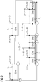
- FIG. 3 shows a device 4 according to an embodiment of the invention.
- This device 4 also includes a process simulation device 1 and a control simulation device 2, which are connected to one another for data transmission.
- the process simulation device 1 comprises an execution system 16 by means of which the simulation of the physical process of the machine or installation can be carried out. This execution system 16 is supplied with a simulation model 17 or a logical model.
- the process simulation device 1 comprises a buffer 11 for the input values and a buffer 12 for the output values.
- the process simulation device 1 comprises a virtual clock 13, which in accordance with the execution of the simulation progresses.
- the process simulation device 1 comprises an event receiver 14, which will be explained in more detail below.
- the process simulation device 1 comprises a device 15 for adapting a step size of the simulation steps S 1 .
- the control simulation device 2 comprises an execution system 25 for carrying out the simulation, which may be designed according to the standard IEC 61131, for example. Also, this execution system 25, a simulation model 26 is supplied. Furthermore, the control simulation device 2 comprises a buffer 21 for the input values and a buffer 22 for the output values. The control simulation device 2 also includes a virtual clock 23, which progresses when the simulation is performed. Finally, the control simulation device 2 comprises an event generator 24.
- the event generator 24 outputs an event signal each time a simulation step S 2 has been completed with the control simulation device 2.
- the event generator 24 may output an event signal if a main cycle of the controller or the programmable logic controller has been performed in the simulation.
- This event signal comprises the corresponding result time t i of the virtual time.
- the event signal is transmitted to the event receiver 14 of the process simulation device 1.
- the output values for this result time t i are transmitted to the process simulation device 1 by means of the control simulation device 2.
- the writing ranges or time durations of the respective simulation steps S 1 are adapted by means of the process simulation device 1 with the device 15 in such a way that they deliver a result at the result time t i .
- a solver of the simulation can also be used to calculate intermediate steps.
- H k + 1 H k ⁇ ⁇ ⁇ y k + 1 - y t k + 1 ⁇ ,
- t i be the virtual time of the last event.
- FIG. 4 shows a time sequence of the simulation steps S 1 and S 2 , which with the device 4 according to FIG. 3 be performed.
- the time duration or the step size of the simulation steps S 1 carried out first has been adapted by means of the process simulation device 1 .
- the time duration of the last simulation step S 1 was reduced from 10 ms to 5 ms.
- the process simulation device 1 comprises the buffer 11 for the input values and the state of the simulation model.
- this buffer 11 certain results previously received from the control simulation device 2 may also be previously stored.
- the received result time t i which is determined on the basis of the virtual clock 23 of the control simulation device 2, is obtained by means of process simulation device 1 with the time t k + 1 of the virtual clock 13 of the process simulation device 1 compared.
- the process simulation device 1 then deletes all calculated results or output values in the buffer 12, which were determined after the result time t i .
- the process simulation device 1 carries out a new simulation, in which case the input values with the largest time stamp, which were determined before the result time t i , are used.
- the step sizes of the simulation steps S 1 are dependent on the result time t i - as described above - adapted.
- the process simulation device 1 empties the buffer 11 and uses the values it has received along with the event signal.
- the process simulation device 1 and the control simulation device 2 are allowed to always operate with actual values.
- the method can also be extended to a plurality of process simulation devices 1 and / or a plurality of control simulation devices 2.
- all simulation devices which exchange data with at least one control simulation device 2 can adapt the step size or the duration of the simulation steps S 1 as described above.
- the time duration of the simulation steps S 2 of the control simulation device is not changed since this reflects the real behavior of a programmable logic controller according to the standard IEC 61131. It is hereby required that the controller (with the exception of special events) read the input values at the beginning of a main cycle and ignore any changes in the input values during the execution of the main cycle. In contrast, a realistic simulation of the controlled process should take into account the exact time at which the controller affects the process.
Landscapes
- Engineering & Computer Science (AREA)
- Physics & Mathematics (AREA)
- General Physics & Mathematics (AREA)
- Automation & Control Theory (AREA)
- Theoretical Computer Science (AREA)
- Computer Hardware Design (AREA)
- Evolutionary Computation (AREA)
- Geometry (AREA)
- General Engineering & Computer Science (AREA)
- Management, Administration, Business Operations System, And Electronic Commerce (AREA)
- Testing And Monitoring For Control Systems (AREA)
- Programmable Controllers (AREA)
Abstract
Description
- Die vorliegende Erfindung betrifft eine Vorrichtung zum Simulieren einer gesteuerten Maschine oder Anlage umfassend eine Prozesssimulationseinrichtung, welche dazu ausgebildet ist, zum Simulieren eines physikalischen Prozesses der Maschine oder Anlage Simulationsschritte durchzuführen. Zudem umfasst die Vorrichtung eine Steuerungssimulationseinrichtung, welche dazu ausgebildet ist, zum Simulieren einer Steuerung der Maschine oder Anlage Simulationsschritte durchzuführen. Dabei sind die Prozesssimulationseinrichtung und die Steuerungssimulationseinrichtung dazu ausgebildet, zum Simulieren der gesteuerten Maschine oder Anlage in den jeweiligen Simulationsschritten bestimmte Ausgangswerte auszutauschen. Zudem betrifft die vorliegende Erfindung ein Verfahren zum Simulieren einer gesteuerten Maschine oder Anlage.
- Um ein automatisiertes System, wie eine gesteuerte Maschine, eine gesteuerte Anlage, eine Roboterzelle oder einen Produktionsprozess zu simulieren, ist es erforderlich, dass der physische Prozess in Kombination mit einer Simulation der Steuerung, beispielsweise des Steuerungsprogramms der Automatisierung, simuliert wird. In der Regel wird der physikalische Prozess mathematisch modelliert und mit entsprechenden Simulationswerkzeugen simuliert. Wenn die Untersuchung aber eine genaue Analyse der Regelstrecke fordert, ist es sinnvoll, das ursprüngliche Steuerungsprogramm in einer Softwareemulierten Steuerung ausgeführt wird.
- In diesem Fall besteht das Problem darin, dass sich ein physikalischer Prozess ständig ändert und zudem mit der Umgebung interagiert. Eine Steuerung hingegen interagiert nur zu bestimmten Zeitpunkten, die nicht allgemein im Voraus bekannt sind. Simulationswerkzeuge verfügen über eine eigene interne Schrittweitensteuerung für die Simulationsschritte, die bestimmt, für welche Zeitpunkte die Ergebnisse berechnet werden sollen. Diese Simulationsschritte sind nicht mit den Interaktionspunkten der Steuerung synchronisiert. Daher wird die Simulation insgesamt immer einen systematischen Simulationsfehler aufweisen, weil die Simulation des physikalischen Prozesses ihre Berechnung mit veralteten Eingabewerten der Simulation der Steuerung durchführt.
- Bis jetzt wurde dieses Problem noch nicht gelöst. Das Verhalten der emulierten Steuerung ist eine exakte Nachbildung des Verhaltens einer realen Steuerung, beispielsweise einer speicherprogrammierbaren Steuerung. Hierbei gibt es einzelne Zeitpunkte, an denen eine Interaktion mit der Umgebung möglich ist, wobei diese im Allgemeinen unbekannt sind. Das Verhalten der Emulation kann nicht verändert werden, ohne dass die Gültigkeit des Simulationsergebnisses verloren geht. Wenn möglich, wird die Simulation des physikalischen Prozesses typischerweise auf eine feste Schrittweite gesetzt, um ein besser vorhersagbares Timing-Verhalten zu erhalten. Dies geht aber auf Kosten der Leistung und/oder der Genauigkeit. Der resultierende Simulationsfehler ist manchmal akzeptabel, mit anderen Worten kann die Simulation "gut genug" sein. Aber vor allem bei der Simulation von Systemen, in denen das Timing kritisch ist, sind die verfügbaren Setups nicht verwendbar. Der systematische Simulationsfehler kann durch eine erhebliche Reduzierung der Simulationsschrittweite reduziert werden. Dies führt jedoch zu einem höheren Rechenaufwand und einer geringeren Leistung.
- Es ist Aufgabe der vorliegenden Erfindung, eine Lösung aufzuzeigen, wie eine gesteuerte Maschine oder Anlage mit geringem Rechenaufwand zuverlässiger simuliert werden kann.
- Diese Aufgabe wird durch eine Vorrichtung sowie durch ein Verfahren mit den Merkmalen der jeweiligen unabhängigen Patentansprüche gelöst. Vorteilhafte Weiterbildungen der Erfindung sind in den abhängigen Patentansprüchen angegeben.
- Eine erfindungsgemäße Vorrichtung zum Simulieren einer gesteuerten Maschine oder Anlage umfasst eine Prozesssimulationseinrichtung, welche dazu ausgebildet ist, zum Simulieren eines physikalischen Prozesses der Maschine oder Anlage Simulationsschritte durchzuführen. Zudem umfasst die Vorrichtung eine Steuerungssimulationseinrichtung, welche dazu ausgebildet ist, zum Simulieren einer Steuerung der Maschine oder Anlage Simulationsschritte durchzuführen. Die Prozesssimulationseinrichtung und die Steuerungssimulationseinrichtung sind dazu ausgebildet, zum Simulieren der gesteuerten Maschine oder Anlage in den jeweiligen Simulationsschritten bestimmte Ausgangswerte auszutauschen. Ferner ist es vorgesehen, dass die Steuerungssimulationseinrichtung dazu ausgebildet ist, an die Prozesssimulationseinrichtung eine Information zu übertragen, welche einen Ergebniszeitpunkt für ein Ende eines mit der Steuerungssimulationseinrichtung durchgeführten Simulationsschritts beschreibt. Außerdem ist die Prozesssimulationseinrichtung dazu ausgebildet, eine Zeitdauer zumindest eines mit der Simulationsschritte in Abhängigkeit von dem Ergebniszeitpunkt anzupassen.
- Mithilfe der Prozesssimulationseinrichtung kann das Verhalten der Maschine oder Anlage im Betrieb simuliert werden. Mit der Vorrichtung soll also ein automatisiertes System simuliert werden, welche eine Steuerung und die Maschine oder Anlage umfasst, wobei ein Betrieb der Maschine oder Anlage mittels der Steuerung gesteuert und/oder geregelt wird. Mittels der Steuerungssimulationseinrichtung kann das Verhalten der Steuerung beim Steuern beziehungsweise Regeln der Maschine oder Anlage simuliert werden. Insbesondere kann mittels der Steuerungssimulationseinrichtung eine Steuerung simuliert werden, welche als speicherprogrammierbare Steuerung (SPS) ausgebildet ist. Mit der Steuerungssimulationseinrichtung können die zeitlich aufeinanderfolgenden Simulationsschritte durchgeführt werden, um das Verhalten der speicherprogrammierbaren Steuerung nachzubilden. Beispielsweise kann mittels der Steuerungssimulationseinrichtung eine Regelstrecke zum Regeln der Maschinen oder Anlage simuliert werden. Die Steuerungssimulationseinrichtung umfasst insbesondere einen Emulator, auf welchem das reale Steuerungsprogramm der Steuerung zum Ablauf gebracht wird. Dies bringt den Vorteil mit sich, dass das Verhalten des realen Steuerprogramms untersucht werden kann. Somit ist es beispielsweise nicht erforderlich, dass das Verhalten der Steuerung beispielsweise mathematisch beschrieben wird und mit einem entsprechenden Simulationswerkzeug nachgebildet wird. Mit der Prozesssimulationseinrichtung können ebenfalls die zeitlich aufeinanderfolgen Simulationsschritte durchgeführt werden. In den jeweiligen Simulationsschritten werden Ausgangswerte bestimmt, welche das physikalische Verhalten der Maschine oder Anlage beschreiben. Beispielsweise können die Ausgangswerte eine Position, eine Geschwindigkeit, eine Beschleunigung oder dergleichen beschreiben.
- Die jeweiligen Simulationsschritte, die mit der Steuerungssimulationseinrichtung und der Prozesssimulationseinrichtung durchgeführt werden, werden in Abhängigkeit von einer virtuellen Zeit bestimmt. Die Steuerungssimulationseinrichtung und die Prozesssimulationseinrichtung können beispielsweise sequentiell betrieben werden. Mittels der Steuerungssimulationseinrichtung können in den jeweiligen Simulationsschritten Ausgangswerte bestimmt werden und an die Prozesssimulationseinrichtung übertragen werden. Diese Ausgangswerte können von der Prozesssimulationseinrichtung als Eingangswerte für die nachfolgenden Simulationsschritte verwendet werden. In gleicher Weise können die Ausgangswerte, die mittels der Prozesssimulationseinrichtung bestimmt werden, als Eingangswerte für die nachfolgenden Simulationsschritte der Steuerungssimulationseinrichtung verwendet werden. Somit kann eine Co-Simulation ermöglicht werden.
- Gemäß der vorliegenden Erfindung ist es vorgesehen, dass die Steuerungssimulationseinrichtung einen Ergebniszeitpunkt bestimmen, welcher einen Zeitpunkt beziehungsweise einen virtuellen Zeitpunkt beschreibt, an welchem einer der Simulationsschritte beendet wurde. Die Steuerungssimulationseinrichtung kann beispielsweise für jeden Simulationsschritt, der durchgeführt wird, einen Ergebniszeitpunkt bestimmen. Dieser Ergebniszeitpunkt wird dann von der Steuerungssimulationseinrichtung an die Prozesssimulationseinrichtung übertragen. Nach dem Empfangen kann die Prozesssimulationseinrichtung den zumindest einen Simulationsschritt, welcher nachfolgend mit dieser durchgeführt wird, an diesen Ergebniszeitpunkt anpassen. Insbesondere kann mit der Prozesssimulationseinrichtung eine Schrittweite beziehungsweise eine Zeitdauer des zumindest einen Simulationsschritts angepasst werden. Damit wird es ermöglicht, dass die Schrittweiten der Prozesssimulation dynamisch an die Schrittweiten der Simulation der Steuerung angepasst werden. Dadurch kann verhindert werden, dass in der Co-Simulation veraltete Eingangswerte verwendet werden und somit ein Simulationsfehler auftritt. Insgesamt kann somit die Simulation der gesteuerten Maschine oder Anlage zuverlässiger durchgeführt werden.
- Bevorzugt ist die Prozesssimulationseinrichtung dazu ausgebildet, die Zeitdauer des zumindest einen Simulationsschritts, welcher mit dieser durchgeführt wird, so anzupassen, das der zumindest einen Simulationsschritt zu dem Ergebniszeitpunkt endet. Mit der Steuerungssimulationseinrichtung kann beispielsweise ein Hauptzyklus der Steuerung simuliert werden. Der Ergebniszeitpunkt beschreibt, bis zu welcher virtuellen Zeit dieser Hauptzyklus simuliert wurde. Mit der Prozesssimulationseinrichtung können dann ein oder mehrere Simulationsschritte während eines Simulationszyklus durchgeführt werden. Die jeweilige zeitliche Dauer der Simulationsschritte kann so bestimmt werden, dass der Simulationszyklus zu dem Ergebniszeitpunkt endet. Somit können die Simulation des physikalischen Prozesses und die Simulation der Steuerung jeweils bis zu dem Ergebniszeitpunkt durchgeführt werden. Für nachfolgende Simulationszyklen können die jeweils bestimmten Ausgangswerte zwischen der Prozesssimulationseinrichtung und der Steuerungssimulationseinrichtung ausgetauscht werden. Somit kann verhindert werden, dass veraltete Ausgangswerte bei der Simulation verwendet werden.
- Vorzugsweise weist die Prozesssimulationseinrichtung eine Einrichtung auf, welche dazu ausgebildet ist, die zeitliche Dauer des zumindest einen Simulationsschritts in Abhängigkeit von dem Ergebniszeitpunkt anzupassen. Sowohl die Prozesssimulationseinrichtung als auch die Steuerungssimulationseinrichtung können jeweils eine virtuelle Uhr umfassen. Anhand der virtuellen Uhr kann die Steuerungssimulationseinrichtung den Ergebniszeitpunkt bestimmen. Nach dem Empfangen des Ergebniszeitpunkts kann dann die Prozesssimulationseinrichtung ihre virtuelle Uhr nutzen, um zu bestimmen, wie die Schrittweiten der Simulationsschritte angepasst werden soll.
- In einer weiteren Ausgestaltung weist die Steuerungssimulationseinrichtung einen Ereignisgenerator auf, welcher dazu ausgebildet ist, ein Ereignissignal zu erzeugen, wobei das Ereignissignal den Ergebniszeitpunkt beschreit. Zudem kann die Prozesssimulationseinrichtung einen Ereignisempfänger zum Empfangen des Ereignissignals aufweisen. Mithilfe der Steuerungssimulationseinrichtung kann also ein Ereignis erzeugt werden, falls ein Simulationsschritt beendet wurde. Zusätzlich zu dem Ereignissignal kann die Steuerungssimulationseinrichtung auch die in dem Simulationsschritt bestimmen Ausgangswerte an die Prozesssimulationseinrichtung übertragen. Damit kann die Co-Simulation präzise durchgeführt werden.
- Weiterhin ist es vorteilhaft, wenn die Steuerungssimulationseinrichtung dazu ausgebildet ist, die in einem Simulationsschritt bestimmten Ausgangswerte an die Prozesssimulationseinrichtung zu übertragen und die Prozesssimulationseinrichtung dazu ausgebildet ist, diese Ausgangswerte als Eingangswerte für den zumindest einen durchgeführten Simulationsschritt zu verwenden. Es kann auch vorgesehen sein, dass Prozesssimulationseinrichtung dazu ausgebildet ist, die in einem Simulationsschritt bestimmten Ausgangswerte an die Steuerungssimulationseinrichtung zu übertragen und die Steuerungssimulationseinrichtung dazu ausgebildet ist, diese Ausgangswerte als Eingangswerte für einen nachfolgend durchgeführten Simulationsschritt zu verwenden. Auf diese Weise wird eine Co-Simulation ermöglicht, um das Verhalten der gesteuerten Maschine oder Anlage vorherzusagen.
- In einer weiteren Ausführungsform weist die Prozesssimulationseinrichtung einen Puffer zum Speichern der Eingangswerte auf. Hierbei ist es insbesondere vorgesehen, dass die Prozesssimulationseinrichtung dazu ausgebildet ist, zumindest einen der gespeicherten Eingangswerte in Abhängigkeit von einem Zeitpunkt, an welchem dieser bestimmt wurde, auszuwählen. Mithilfe der Vorrichtung kann in vorteilhafter Weise auch eine parallele Ausführung der Simulation des physikalischen Prozesses und der Simulation der Steuerung ermöglicht werden. Die Prozesssimulationseinrichtung weist den Puffer auf, in dem eine Sequenz von Eingangswerten gespeichert werden kann. Wenn mittels der Prozesssimulationseinrichtung eine neue Simulation gestartet wird beziehungsweise ein neuer Simulationszyklus begonnen wird, können aus dem Puffer diejenigen Eingangswerten ausgewählt werden, welche zu einem möglichst späten Zeitpunkt bestimmt wurden beziehungsweise welche den höchsten Zeitstempel aufweisen. Bei der Auswahl der Eingangswerte ist zudem zu berücksichtigen, dass diese zu einem Zeitpunkt vor dem Ergebniszeitpunkt bestimmt wurden. Für diese Simulation kann dann die Zeitdauer des zumindest einen Simulationsschritts an den Ergebniszeitpunkt angepasst werden.
- Ferner ist es vorteilhaft, wenn die Prozesssimulationseinrichtung einen Puffer zum Speichern der Ausgangswerte aufweist, wobei die Prozesssimulationseinrichtung dazu ausgebildet ist, Ausgangswerten, welche nach dem Ergebniszeitpunkt bestimmt wurden, zu löschen. Für eine nachfolgende Simulation beziehungsweise einen nachfolgenden Simulationszyklus kann die Prozesssimulationseinrichtung den Puffer leeren und nur diejenigen Eingangswerte verwenden, welche diese zusammen mit dem Ergebniszeitpunkt erhalten hat. Somit arbeiten die Prozesssimulationseinrichtung und die Steuerungssimulationseinrichtung immer mit aktuellen Eingangswerten.
- Wie bereits erläutert, weist die Steuerungssimulationseinrichtung bevorzugt einen Emulator zum Durchführen eines Steuerprogramms der Steuerung auf. Auf diesem Emulator kann das reale Steuerprogramm beziehungsweise die reale Steuerungssoftware der speicherprogrammierbaren Steuerung nachgebildet werden. Somit dann die Steuerung und/oder Regelung der Maschine oder Anlage realitätsnah simuliert werden.
- In einer weiteren Ausführungsform ist es vorgesehen, dass die Vorrichtung eine Mehrzahl von Prozesssimulationseinrichtungen und/oder eine Mehrzahl von Steuerungssimulationseinrichtungen umfasst. Mit anderen Worten kann das Verfahren auf mehrere Prozesssimulationseinrichtungen und/oder mehrere Steuerungssimulationseinrichtungen erweitert werden. Auch hier ist es insbesondere vorgesehen, dass mit jeder der Steuerungssimulationseinrichtungen ein Ergebniszeitpunkt bestimmt wird und an die Steuerungssimulationseinrichtungen übertragen wird. Die Steuerungssimulationseinrichtungen kann die jeweilige zeitliche Dauer der Simulationsschritte an den Ergebniszeitpunkt anpassen.
- Ein erfindungsgemäßes Verfahren dient zum Simulieren einer gesteuerten Maschine oder Anlage. Das Verfahren umfasst das Simulieren eines physikalischen Prozesses der Maschine oder Anlage durch Durchführen von Simulationsschritten mittels einer Prozesssimulationseinrichtung. Zudem beinhaltet das Verfahren das Simulieren einer Steuerung der Maschine oder Anlage durch Durchführen von Simulationsschritten mittels einer Steuerungssimulationseinrichtung. Ferner umfasst das Verfahren das Austauschen von in den jeweiligen Simulationsschritten bestimmten Ausgangswerte zwischen der Prozesssimulationseinrichtung und der Steuerungssimulationseinrichtung zum Simulieren der gesteuerten Maschine oder Anlage. Dabei ist es vorgesehen, dass mittels der Steuerungssimulationseinrichtung an die Prozesssimulationseinrichtung eine Information übertragen wird, welche einen Ergebniszeitpunkt für ein Ende eines mit der Steuerungssimulationseinrichtung durchgeführten Simulationsschritts beschreibt, und dass mittels der Prozesssimulationseinrichtung eine Zeitdauer zumindest eines der Simulationsschritte in Abhängigkeit von dem Ergebniszeitpunkt angepasst wird.
- Die mit Bezug auf die erfindungsgemäße Vorrichtung vorgestellten bevorzugten Ausführungsformen und deren Vorteile gelten entsprechend für das erfindungsgemäße Verfahren.
- Weitere Merkmale der Erfindung ergeben sich aus den Ansprüchen, den Figuren und der Figurenbeschreibung. Die vorstehend in der Beschreibung genannten Merkmale und Merkmalskombinationen sowie die nachfolgend in der Figurenbeschreibung genannten und/oder in den Figuren alleine gezeigten Merkmale und Merkmalskombinationen sind nicht nur in der jeweils angegebenen Kombination, sondern auch in anderen Kombinationen verwendbar, ohne den Rahmen der Erfindung zu verlassen.
- Die Erfindung wird nun anhand von bevorzugten Ausführungsbeispielen sowie unter Bezugnahme auf die beigefügten Zeichnungen näher erläutert. Dabei zeigen:
- FIG 1
- eine Vorrichtung zum Simulieren einer gesteuerten Maschine oder Anlage gemäß dem Stand der Technik;
- FIG 2
- einen zeitlichen Ablauf von Simulationsschritten, welche mit der Vorrichtung gemäß
FIG 1 durchgeführt werden; - FIG 3
- eine Vorrichtung zum Simulieren einer gesteuerten Maschine oder Anlage gemäß einer Ausführungsform der Erfindung; und
- FIG 4
- einen zeitlichen Ablauf von Simulationsschritten, welche mit der Vorrichtung gemäß
FIG 3 durchgeführt werden. - In den Figuren werden gleiche oder funktionsgleiche Elemente mit den gleichen Bezugszeichen versehen.
-
FIG 1 zeigt eine Vorrichtung 4 zum Simulieren einer gesteuerten Maschine oder Anlage gemäß dem Stand der Technik. Die Vorrichtung 4 umfasst eine Prozesssimulationseinrichtung 1, welche dazu dient, einen physikalischen Prozess der Maschine oder Anlage zu simulieren. Darüber hinaus umfasst die Vorrichtung 4 eine Steuerungssimulationseinrichtung 2, welche dazu dient, eine Steuerung, mittels welcher die Maschine oder Anlage gesteuert wird, zu simulieren. Bei der Steuerung, welche mittels der Steuerungssimulationseinrichtung 2 simuliert wird, kann es sich beispielsweise um eine speicherprogrammierbare Steuerung handeln. Die Steuerungssimulationseinrichtung 2 kann durch eine Software-Emulation beziehungsweise einen Emulator bereitgestellt werden. Vorliegend wird mittels der Prozesssimulationseinrichtung 1 und der Steuerungssimulationseinrichtung 2 eine Co-Simulation durchgeführt, um den Betrieb der gesteuerten Maschine oder Anlage nachzubilden. - Die Prozesssimulationseinrichtung 1 und die Steuerungssimulationseinrichtung 2 sind zur Datenübertragung miteinander verbunden. Mittels der Prozesssimulationseinrichtung 1 können Simulationsschritte S1 durchgeführt werden und hierbei Ausgangswerte bestimmt werden. Dies ist vorliegend durch den Pfeil 5 veranschaulicht. Diese Ausgangswerte beschreiben physikalische Größen der Maschine oder Anlage. Die Ausgangswerte beziehungsweise die physikalischen Größen können beispielsweise eine Position, eine Geschwindigkeit und/oder eine Beschleunigung beschreiben. Die von der Prozesssimulationseinrichtung 1 bereitgestellten Ausgangswerte können von der Steuerungssimulationseinrichtung 2 als Eingabewerte empfangen werden (Pfeil 6). Mittels der Steuerungssimulationseinrichtung 2 können ebenfalls Ausgangswerte bereitgestellt werden. Dies ist vorliegend durch den Pfeil 7 gezeigt. Diese Ausgangswerte können beispielsweise einen elektrischen Strom, eine elektrische Spannung und/oder eine Frequenz beschreiben. Die von der Steuerungssimulationseinrichtung 2 bereitgestellten Ausgangswerte können wiederum von der Prozesssimulationseinrichtung 1 als Eingabewerte empfangen werden (Pfeil 8). In dem vorliegenden Beispiel sind die Prozesssimulationseinrichtung 1 und die Steuerungssimulationseinrichtung 2 über eine Komponente 3 miteinander verbunden. Mittels der Komponente 3 kann der Datenaustausch zwischen der Prozesssimulationseinrichtung 1 und der Steuerungssimulationseinrichtung 2 gesteuert werden. Auf diese Weise wird eine indirekte Datenverbindung zwischen der Prozesssimulationseinrichtung 1 und der Steuerungssimulationseinrichtung 2 realisiert.
-
FIG 2 zeigt einen zeitlichen Ablauf der Simulationsschritte S1, die mit der Prozesssimulationseinrichtung 1 und der Steuerungssimulationseinrichtung 2 durchgeführt werden. Dabei sind die jeweiligen Simulationsschritte S1 bezüglich einer virtuellen Zeit t dargestellt. Die jeweils beschrieben Zeitdauern und Zeitpunkte in vorliegenden in ms (Millisekunden) angegeben. Da die Prozesssimulationseinrichtung 1 und die Steuerungssimulationseinrichtung 2 bei der Co-Simulation die Eingabewerte und/oder Ausgangswerte austauschen müssen, können diese nicht parallel betrieben werden, sondern die jeweiligen Simulationsschritte S werden sequenziell durchgeführt. Zu einem Zeitpunkt t = 0 wird die Steuerungssimulationseinrichtung 2 gestartet unter der Verwendung von initialen Eingangswerten (Ereignis A). Dabei wird ein Simulationsschritt S2 durchgeführt und hierbei die Ausgangswerte berechnet. Dieser Simulationsschritt S2 endet zu einem Zeitpunkt t = 35 (Ereignis C). Danach wird die virtuelle Zeit t für die Steuerungssimulationseinrichtung 2 angehalten beziehungsweise eingefroren. - Anschließend daran wird die Prozesssimulationseinrichtung 1 gestartet (Ereignis B). Dabei werden mit der Prozesssimulationseinrichtung 1 zeitlich aufeinanderfolgend Simulationsschritte S1 durchgeführt, wobei vorliegend vier Simulationsschritte S1 durchgeführt werden, deren jeweilige Zeitdauer 10 ms beträgt. Hierbei werden die Simulationsschritte S1 solange durchgeführt, bis ein Zeitpunkt erreicht ist, der nach dem Zeitpunkt t = 35 liegt, nämlich der Zeitpunkt t = 40 (Ereignis E). Dabei können die in dem zuletzt durchgeführten Simulationsschritt S1 bestimmten Ergebnisse nicht als Eingabewerte für die Steuerungssimulationseinrichtung 2 verwendet werden, da dadurch die korrekte Abfolge der Ereignisse verletzt werden würde. Daher wird das Ergebnis, welches zum Zeitpunkt t = 30 bestimmt wurde, als Eingangswert für die Steuerungssimulationseinrichtung 2 verwendet (Ereignis D). Aus dem gleichen Grund wird das Ergebnis der Steuerungssimulationseinrichtung 2, welches zu dem Zeitpunkt t = 35 bestimmt wurde, als Eingangswert für die Prozesssimulationseinrichtung 1 zum Zeitpunkt t = 40 verwendet (Ereignis G).
- Nachfolgend wird mittels der Steuerungssimulationseinrichtung 2 ein weiterer Simulationsschritt S2, welcher zu dem Zeitpunkt t = 51 endet (Ereignis F). Danach werden mittels der Prozesssimulationseinrichtung 1 drei aufeinanderfolgende Simulationsschritte S1 mit einer jeweiligen Zeitdauer von 10 ms durchgeführt. Hier werden die Ergebnisse, welche die Steuerungssimulationseinrichtung 2 für den Zeitpunkt t = 51 bestimmt hat, als Eingangswerte für den Zeitpunkt t = 60 verwendet (Ereignis H). Dies führt insgesamt dazu, dass die beiden durchgeführten Simulationen mit Eingangswerten arbeiten, welche bezüglich der Zeit nicht synchronisiert sind. Daher wird ein Simulationsfehler der gesamten Co-Simulation unnötig groß werden.
-
FIG 3 zeigt eine Vorrichtung 4 gemäß einer Ausführungsform der Erfindung. Auch diese Vorrichtung 4 umfasst eine Prozesssimulationseinrichtung 1 und eine Steuerungssimulationseinrichtung 2, welche zur Datenübertragung miteinander verbunden sind. Die Prozesssimulationseinrichtung 1 umfasst ein Ausführungssystem 16, mittels welchem die Simulation des physikalischen Prozesses der Maschine oder Anlage durchgeführt werden kann. Diesem Ausführungssystem 16 wird ein Simulationsmodell 17 beziehungsweise ein logisches Modell zugeführt. Des Weiteren umfasst die Prozesssimulationseinrichtung 1 einen Puffer 11 für die Eingangswerte und einem Puffer 12 für die Ausgangswerte. Darüber hinaus umfasst die Prozesssimulationseinrichtung 1 eine virtuelle Uhr 13, welche in Übereinstimmung mit der Durchführung der Simulation fortschreitet. Ferner umfasst die Prozesssimulationseinrichtung 1 einen Ereignisempfänger 14, welcher nachfolgend näher erläutert wird. Schließlich umfasst die Prozesssimulationseinrichtung 1 eine Einrichtung 15 zur Anpassung einer Schrittweite der Simulationsschritte S1. - Die Steuerungssimulationseinrichtung 2 umfasst ein Ausführungssystem 25 zum Durchführen der Simulation, welche beispielsweise gemäß dem Standard IEC 61131 ausgebildet sein kann. Auch diesem Ausführungssystem 25 wird ein Simulationsmodell 26 zugeführt. Ferner umfasst die Steuerungssimulationseinrichtung 2 einen Puffer 21 für die Eingangswerte sowie einen Puffer 22 für die Ausgangswerte. Auch die Steuerungssimulationseinrichtung 2 umfasst eine virtuelle Uhr 23, welche fortschreitet, wenn die Simulation durchgeführt wird. Schließlich umfasst die Steuerungssimulationseinrichtung 2 einen Ereignisgenerator 24.
- Dabei ist es vorgesehen, dass der Ereignisgenerator 24 jedes Mal ein Ereignissignal ausgibt, wenn ein Simulationsschritt S2 mit der Steuerungssimulationseinrichtung 2 beendet wurde. Beispielsweise kann der Ereignisgenerator 24 ein Ereignissignal ausgeben, falls ein Hauptzyklus der Steuerung beziehungsweise der speicherprogrammierbaren Steuerung in der Simulation durchgeführt wurde. Dieses Ereignissignal umfasst dabei den entsprechenden Ergebniszeitpunkt ti der virtuellen Uhrzeit. Das Ereignissignal wird dabei an den Ereignisempfänger 14 der Prozesssimulationseinrichtung 1 übertragen. Ferner werden mittels der Steuerungssimulationseinrichtung 2 die Ausgangswerte für diesen Ergebniszeitpunkt ti zu der Prozesssimulationseinrichtung 1 übertragen. Nach dem Empfangen des Ereignissignals werden mittels der Prozesssimulationseinrichtung 1 mit der Einrichtung 15 die Schriftweiten beziehungsweise Zeitdauern der jeweiligen Simulationsschritte S1 derart angepasst, dass diese zu dem Ergebniszeitpunkt ti ein Ergebnis liefern. In Abhängigkeit von dem Ausführungssystem 16 beziehungsweise einem Solver der Simulation können auch Zwischenschritte berechnet werden.
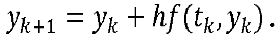
- Um mittels der Einrichtung 15 die Schrittweite anzupassen werden numerische Solver erweitert. Beispielhaft wird vorliegend das explizite Euler-Verfahren verwendet, welches dazu dient, einfache Differentialgleichungen mit einem gegebenen Anfangswert zu lösen. Dabei kann das Problem in Form einer Differentialgleichung gegeben sein:

- Dann kann die Näherung yk der aktuellen Funktionswerte y(tk) mit den diskreten Zeitschritten tk = t0 + kh und der Schrittweite h berechnet werden:
- Typischerweise wird die Schrittweite h so kontrolliert, dass die Schritte möglichst groß (aber begrenzt) sind und dass sichergestellt wird, dass der lokale Fehler unterhalb einer Schwelle ist:

- Hieraus ergibt sich:

- Durch die Erweiterung des Algorithmus kann das folgenden eingeführt werden: Es sei ti die virtuelle Zeit des letzten Ereignisses. Für jeden der Simulationsschritte S1 wird die Schrittweite hk+1 und die hieraus resultierende virtuelle Zeit tk+1 bestimmt. Falls tk+1 > ti ist, wird die Schrittweite zu hk+1 = ti - tk gesetzt. Ferner wird das Ereignis verworfen.
- Hieraus ergibt sich insgesamt, dass die Prozesssimulationseinrichtung 1 und die Steuerungssimulationseinrichtung 2 immer mit aktuellen Eingangswerten arbeiten. Dies ist in
FIG 4 dargestellt, welche einen zeitlichen Ablauf der Simulationsschritte S1 und S2 zeigt, die mit der Vorrichtung 4 gemäßFIG 3 durchgeführt werden. Dabei ist zu erkennen, dass mittels der Prozesssimulationseinrichtung 1 die zeitliche Dauer beziehungsweise die Schrittweite der zuerst durchgeführten Simulationsschritte S1 angepasst wurde. Die zeitliche Dauer des letzten Simulationsschritts S1 wurde von 10 ms auf 5 ms verringert. Somit enden die vier aufeinanderfolgenden Simulationsschritte S1 insgesamt nach einem Zeitpunkt von t = 35 (Ereignis E), welcher dem Ergebniszeitpunkt ti entspricht. In gleicher Weise wurden die mit der Prozesssimulationseinrichtung 1 nachfolgend durchgeführten Simulationsschritte S1 so angepasst, dass diese zu dem Zeitpunkt t = 51 enden. - Gemäß einer Erweiterung kann auch einen parallele Durchführung der Simulationen vorgesehen sein. Wie bereits beschrieben, umfasst die Prozesssimulationseinrichtung 1 den Puffer 11 für die Eingangswerte und den Zustand des Simulationsmodells. In diesem Puffer 11 können auch zuvor bestimmte Ergebnisse, die von der Steuerungssimulationseinrichtung 2 empfangen wurden, gespeichert werden. In Analogie zu dem zuvor beschriebenen Verfahren beziehungsweise Algorithmus, wird mittels Prozesssimulationseinrichtung 1 beim Empfangen des Ereignissignals der empfangene Ergebniszeitpunkt ti, der anhand der virtuellen Uhr 23 der Steuerungssimulationseinrichtung 2 bestimmt wird, mit der Zeit tk+1 der virtuellen Uhr 13 der Prozesssimulationseinrichtung 1 verglichen. Die Prozesssimulationseinrichtung 1 löscht dann alle berechneten Ergebnisse beziehungsweise Ausgangswerte in dem Puffer 12, die nach dem Ergebniszeitpunkt ti bestimmt wurden. Im Anschluss daran führt die Prozesssimulationseinrichtung 1 eine neue Simulation durch, wobei hier die Eingangswerte mit dem größten Zeitstempel, die vor dem Ergebniszeitpunkt ti bestimmt wurden, verwendet werden. Für diese Simulation werden die Schrittweiten der Simulationsschritte S1 in Abhängigkeit von dem Ergebniszeitpunkt ti - wie zuvor beschrieben - angepasst. Für die nächste Simulation kann leert die Prozesssimulationseinrichtung 1 dann den Puffer 11 und verwendet die Werte, die sie zusammen mit dem Ereignissignal erhalten hat. Somit wird es ermöglicht, dass die Prozesssimulationseinrichtung 1 und die Steuerungssimulationseinrichtung 2 immer mit aktuellen Werten arbeiten.
- Das Verfahren kann auch auf mehrere Prozesssimulationseinrichtungen 1 und/oder mehrere Steuerungssimulationseinrichtungen 2 erweitert werden. In diesem Fall können alle Simulationseinrichtungen, die Daten mit zumindest einer Steuerungssimulationseinrichtung 2 austauschen, die Schrittweite beziehungsweise die zeitliche Dauer der Simulationsschritte S1 wie zuvor beschrieben anpassen.
- Vorliegend wird die zeitliche Dauer der Simulationsschritte S2 der Steuerungssimulationseinrichtung nicht verändert, da diese das reale Verhalten einer speicherprogrammierbaren Steuerung gemäß der Norm IEC 61131 wiedergibt. Hier wird gefordert, dass die Steuerung (mit Ausnahme von speziellen Ereignissen) zu Beginn eines Hauptzyklus die Eingangswerte liest und alle Änderungen der Eingangswerte während der Durchführung des Hauptzyklus ignoriert. Im Gegensatz dazu sollte eine realistische Simulation des gesteuerten Prozesses den genauen Zeitpunkt berücksichtigen, zu dem die Steuerung den Prozess beeinflusst.
-
- 1
- Prozesssimulationseinrichtung
- 2
- Steuerungssimulationseinrichtung
- 3
- Komponente
- 4
- Vorrichtung
- 5
- Pfeil
- 6
- Pfeil
- 7
- Pfeil
- 8
- Pfeil
- 11
- Puffer
- 12
- Puffer
- 13
- virtuelle Uhr
- 14
- Ereignisempfänger
- 15
- Einrichtung
- 16
- Ausführungssystem
- 17
- Simulationsmodell
- 21
- Puffer
- 22
- Puffer
- 23
- virtuelle Uhr
- 24
- Ereignisgenerator
- 25
- Ausführungssystem
- 26
- Simulationsmodell
- A
- Ereignis
- B
- Ereignis
- C
- Ereignis
- D
- Ereignis
- E
- Ereignis
- F
- Ereignis
- G
- Ereignis
- H
- Ereignis
- S1
- Simulationsschritt
- S2
- Simulationsschritt
- t
- Zeit
- ti
- Ergebniszeitpunkt
Claims (11)
- Vorrichtung (4) zum Simulieren einer gesteuerten Maschine oder Anlage umfassend:- eine Prozesssimulationseinrichtung (1), welche dazu ausgebildet ist, zum Simulieren eines physikalischen Prozesses der Maschine oder Anlage Simulationsschritte (S1) durchzuführen, und- eine Steuerungssimulationseinrichtung (2), welche dazu ausgebildet ist, zum Simulieren einer Steuerung der Maschine oder Anlage Simulationsschritte (S2) durchzuführen,- wobei die Prozesssimulationseinrichtung (1) und die Steuerungssimulationseinrichtung (2) dazu ausgebildet sind, zum Simulieren der gesteuerten Maschine oder Anlage in den jeweiligen Simulationsschritten (S1, S2) bestimmte Ausgangswerte auszutauschen,dadurch gekennzeichnet, dass- die Steuerungssimulationseinrichtung (2) dazu ausgebildet ist, an die Prozesssimulationseinrichtung (1) eine Information zu übertragen, welche einen Ergebniszeitpunkt (ti) für ein Ende eines mit der Steuerungssimulationseinrichtung (2) durchgeführten Simulationsschritts (S2) beschreibt, und- die Prozesssimulationseinrichtung (1) dazu ausgebildet ist, eine Zeitdauer zumindest eines mit der Simulationsschritte (S1) in Abhängigkeit von dem Ergebniszeitpunkt (ti) anzupassen.
- Vorrichtung (4) nach Anspruch 1, dadurch gekennzeichnet, dass die Prozesssimulationseinrichtung (1) dazu ausgebildet ist, die Zeitdauer des zumindest einen Simulationsschritts (S1), welcher mit dieser durchgeführt wird, so anzupassen, das der zumindest eine Simulationsschritt (S1) zu dem Ergebniszeitpunkt (ti) endet.
- Vorrichtung (4) nach Anspruch 1 oder 2, dadurch gekennzeichnet, dass die Prozesssimulationseinrichtung (1) eine Einrichtung (15) aufweist, welche dazu ausgebildet ist, die zeitliche Dauer des zumindest einen Simulationsschritts (S1) in Abhängigkeit von dem Ergebniszeitpunkt (ti) anzupassen.
- Vorrichtung (4) nach einem der vorhergehenden Ansprüche, dadurch gekennzeichnet, dass die Steuerungssimulationseinrichtung (2) einen Ereignisgenerator (24) aufweist, welcher dazu ausgebildet ist, ein Ereignissignal zu erzeugen, wobei das Ereignissignal den Ergebniszeitpunkt (ti) beschreit, und die Prozesssimulationseinrichtung (1) einen Ereignisempfänger (14) zum Empfangen des Ereignissignals aufweist.
- Vorrichtung (4) nach einem der vorhergehenden Ansprüche, dadurch gekennzeichnet, dass die Steuerungssimulationseinrichtung (2) dazu ausgebildet ist, die bestimmten Ausgangswerte an die Prozesssimulationseinrichtung (1) zu übertragen und die Prozesssimulationseinrichtung (1) dazu ausgebildet ist, diese Ausgangswerte als Eingangswerte für zumindest einen durchgeführten Simulationsschritt (S1) zu verwenden.
- Vorrichtung (4) nach Anspruch 5, dadurch gekennzeichnet, dass die Prozesssimulationseinrichtung (1) einen Puffer (11) zum Speichern der Eingangswerte aufweist.
- Vorrichtung (4) nach Anspruch 6, dadurch gekennzeichnet, dass die Prozesssimulationseinrichtung (1) dazu ausgebildet ist, zumindest einen der gespeicherten Eingangswerte in Abhängigkeit von einem Zeitpunkt, an welchem dieser bestimmt wurde, auszuwählen.
- Vorrichtung (4) nach einem der vorhergehenden Ansprüche, dadurch gekennzeichnet, dass die Prozesssimulationseinrichtung (1) einen Puffer (12) zum Speichern der Ausgangswerte aufweist, wobei die Prozesssimulationseinrichtung (1) dazu ausgebildet ist, Ausgangswerten, welche nach dem Ergebniszeitpunkt (ti) bestimmt wurden, zu löschen.
- Vorrichtung (4) nach einem der vorhergehenden Ansprüche, dadurch gekennzeichnet, dass die Steuerungssimulationseinrichtung (2) einen Emulator zum Durchführen eines Steuerprogramms der Steuerung aufweist.
- Vorrichtung (4) nach einem der vorhergehenden Ansprüche, dadurch gekennzeichnet, dass die Vorrichtung (4) eine Mehrzahl von Prozesssimulationseinrichtungen (1) und/oder eine Mehrzahl von Steuerungssimulationseinrichtungen (2) umfasst.
- Verfahren zum Simulieren einer gesteuerten Maschine oder Anlage mit den Schritten:- Simulieren eines physikalischen Prozesses der Maschine oder Anlage durch Durchführen von Simulationsschritten (S1) mittels einer Prozesssimulationseinrichtung (1),- Simulieren einer Steuerung der Maschine oder Anlage durch Durchführen von Simulationsschritten (S2) mittels einer Steuerungssimulationseinrichtung (2) und- Austauschen von in den jeweiligen Simulationsschritten (S1, S2) bestimmten Ausgangswerten zwischen der Prozesssimulationseinrichtung (1) und der Steuerungssimulationseinrichtung (2) zum Simulieren der gesteuerten Maschine oder Anlage,dadurch gekennzeichnet, dass- mittels der Steuerungssimulationseinrichtung (2) an die Prozesssimulationseinrichtung (1) eine Information übertragen wird, welche einen Ergebniszeitpunkt (ti) für ein Ende eines mit der Steuerungssimulationseinrichtung (2) durchgeführten Simulationsschritts (S2) beschreibt, und- mittels der Prozesssimulationseinrichtung (1) eine Zeitdauer zumindest eines der Simulationsschritte (S1) in Abhängigkeit von dem Ergebniszeitpunkt (ti) angepasst wird.
Priority Applications (3)
| Application Number | Priority Date | Filing Date | Title |
|---|---|---|---|
| EP18154633.4A EP3521949B1 (de) | 2018-02-01 | 2018-02-01 | Vorrichtung zum simulieren einer gesteuerten maschine oder anlage sowie verfahren |
| CN201910102593.5A CN110109372B (zh) | 2018-02-01 | 2019-01-31 | 用于模拟受控制的机器或设施的设备以及方法 |
| US16/264,254 US12032876B2 (en) | 2018-02-01 | 2019-01-31 | Device and method for simulating a controlled machine or installation |
Applications Claiming Priority (1)
| Application Number | Priority Date | Filing Date | Title |
|---|---|---|---|
| EP18154633.4A EP3521949B1 (de) | 2018-02-01 | 2018-02-01 | Vorrichtung zum simulieren einer gesteuerten maschine oder anlage sowie verfahren |
Publications (2)
| Publication Number | Publication Date |
|---|---|
| EP3521949A1 true EP3521949A1 (de) | 2019-08-07 |
| EP3521949B1 EP3521949B1 (de) | 2021-01-13 |
Family
ID=61163499
Family Applications (1)
| Application Number | Title | Priority Date | Filing Date |
|---|---|---|---|
| EP18154633.4A Active EP3521949B1 (de) | 2018-02-01 | 2018-02-01 | Vorrichtung zum simulieren einer gesteuerten maschine oder anlage sowie verfahren |
Country Status (3)
| Country | Link |
|---|---|
| US (1) | US12032876B2 (de) |
| EP (1) | EP3521949B1 (de) |
| CN (1) | CN110109372B (de) |
Families Citing this family (2)
| Publication number | Priority date | Publication date | Assignee | Title |
|---|---|---|---|---|
| EP3521949B1 (de) * | 2018-02-01 | 2021-01-13 | Siemens Aktiengesellschaft | Vorrichtung zum simulieren einer gesteuerten maschine oder anlage sowie verfahren |
| DE102022127868A1 (de) * | 2022-10-21 | 2024-05-02 | Dspace Gmbh | Verfahren zum Durchführen einer Simulation |
Citations (3)
| Publication number | Priority date | Publication date | Assignee | Title |
|---|---|---|---|---|
| DE102007026502A1 (de) * | 2007-06-05 | 2008-12-11 | Siemens Ag | Trainingssystem für ein Automatisierungssystem zur Steuerung eines technischen Prozesses |
| WO2015124170A1 (de) * | 2014-02-18 | 2015-08-27 | Siemens Aktiengesellschaft | Verfahren und vorrichtung zum emulieren einer speicherprogrammierbaren steuerung |
| EP2980661A1 (de) * | 2014-07-30 | 2016-02-03 | Siemens Aktiengesellschaft | Elektronisches Steuerungsgerät |
Family Cites Families (21)
| Publication number | Priority date | Publication date | Assignee | Title |
|---|---|---|---|---|
| US7778806B2 (en) * | 2006-03-29 | 2010-08-17 | Hitachi, Ltd | Method and apparatus for simulating microcomputer-based systems |
| US20080168092A1 (en) * | 2007-01-10 | 2008-07-10 | General Electric Company | Systems and methods for turbine control simulation |
| CN101620548B (zh) | 2008-07-04 | 2013-03-27 | 菲尼克斯电气公司 | 用于计算机模拟设备或者机器的方法和计算机系统 |
| JP5583773B2 (ja) * | 2010-08-20 | 2014-09-03 | インターナショナル・ビジネス・マシーンズ・コーポレーション | シミュレーション方法、システム及びプログラム |
| US10037443B2 (en) * | 2011-03-07 | 2018-07-31 | Rockwell Automation Technologies, Inc. | Industrial simulation using redirected I/O module configurations |
| CN102662428B (zh) * | 2012-03-01 | 2015-02-04 | 中国科学院计算技术研究所 | 一种离散事件网络模拟环境的时钟同步方法 |
| JP5962088B2 (ja) * | 2012-03-15 | 2016-08-03 | オムロン株式会社 | Plcシミュレーションシステム、plcシミュレータ、制御プログラム、および記録媒体 |
| US9251308B2 (en) * | 2012-07-23 | 2016-02-02 | International Business Machines Corporation | Simulation method, system, and program |
| US10755003B2 (en) * | 2013-11-08 | 2020-08-25 | Rockwell Automation Technologies, Inc. | Time synchronization of signal transmission intervals for simulating a machine in industrial automation |
| KR101641853B1 (ko) * | 2014-04-30 | 2016-07-21 | 미쓰비시덴키 가부시키가이샤 | 시뮬레이션 시스템, 프로그래머블 컨트롤러, 시뮬레이션 장치, 엔지니어링 툴 |
| US10496061B2 (en) * | 2015-03-16 | 2019-12-03 | Rockwell Automation Technologies, Inc. | Modeling of an industrial automation environment in the cloud |
| US10012979B2 (en) * | 2016-01-20 | 2018-07-03 | Rockwell Automation Technologies, Inc. | Emulated industrial control execution rate scaling |
| DE102016214117A1 (de) * | 2016-08-01 | 2018-02-01 | Siemens Aktiengesellschaft | Ermitteln einer Ausführungszeit eines Anwenderprogramms |
| EP3349082B1 (de) * | 2017-01-16 | 2019-07-31 | Siemens Aktiengesellschaft | System zur abschaltbaren simulation von anlagen oder maschinen innerhalb von speicherprogrammierbaren steuerungen |
| JP6915441B2 (ja) * | 2017-08-10 | 2021-08-04 | オムロン株式会社 | 情報処理装置、情報処理方法、および情報処理プログラム |
| US10635071B2 (en) * | 2017-09-05 | 2020-04-28 | Mitsubishi Electric Corporation | Simulation device and simulation method |
| JP7087316B2 (ja) * | 2017-09-27 | 2022-06-21 | オムロン株式会社 | 情報処理装置、情報処理方法およびプログラム |
| EP3521949B1 (de) * | 2018-02-01 | 2021-01-13 | Siemens Aktiengesellschaft | Vorrichtung zum simulieren einer gesteuerten maschine oder anlage sowie verfahren |
| EP3540539A1 (de) * | 2018-03-15 | 2019-09-18 | Siemens Aktiengesellschaft | Verfahren zur rechnergestützten simulation des betriebs einer automatisiert arbeitenden maschine |
| US11573542B2 (en) * | 2018-07-13 | 2023-02-07 | Siemens Aktiengesellschaft | Method and apparatus for adjusting process control prediction model and process controller |
| US10949592B1 (en) * | 2020-03-23 | 2021-03-16 | Hitachi Automotive Systems, Ltd. | Co-simulation execution platform |
-
2018
- 2018-02-01 EP EP18154633.4A patent/EP3521949B1/de active Active
-
2019
- 2019-01-31 US US16/264,254 patent/US12032876B2/en active Active
- 2019-01-31 CN CN201910102593.5A patent/CN110109372B/zh active Active
Patent Citations (3)
| Publication number | Priority date | Publication date | Assignee | Title |
|---|---|---|---|---|
| DE102007026502A1 (de) * | 2007-06-05 | 2008-12-11 | Siemens Ag | Trainingssystem für ein Automatisierungssystem zur Steuerung eines technischen Prozesses |
| WO2015124170A1 (de) * | 2014-02-18 | 2015-08-27 | Siemens Aktiengesellschaft | Verfahren und vorrichtung zum emulieren einer speicherprogrammierbaren steuerung |
| EP2980661A1 (de) * | 2014-07-30 | 2016-02-03 | Siemens Aktiengesellschaft | Elektronisches Steuerungsgerät |
Also Published As
| Publication number | Publication date |
|---|---|
| US20190236224A1 (en) | 2019-08-01 |
| CN110109372B (zh) | 2022-08-26 |
| US12032876B2 (en) | 2024-07-09 |
| EP3521949B1 (de) | 2021-01-13 |
| CN110109372A (zh) | 2019-08-09 |
Similar Documents
| Publication | Publication Date | Title |
|---|---|---|
| EP2194432B1 (de) | Scheduling-Verfahren | |
| DE3341766C2 (de) | Verfahren und Vorrichtung zur Identifikation von Daten | |
| DE20321699U1 (de) | Rechner zum Durchführen eines Simulationsverfahrens für eine Bearbeitung eines Werkstücks durch eine Werkzeugmaschine | |
| WO2012168427A1 (de) | Verfahren und system zur simulation eines arbeitsprozesses an einer werkzeugmaschine | |
| EP1906377A1 (de) | System und Verfahren zur Integration eines Prozessleitsystems in einen Trainingssimulator | |
| EP3499470B1 (de) | Verfahren zur zustandsbasierten instandhaltung einer zugangsvorrichtung | |
| EP3188053A1 (de) | Verfahren zum konfigurieren einer co-simulation für ein gesamtsystem | |
| DE112015006067T5 (de) | Intelligentes Funktionsmodul und speicherprogrammierbares Steuerungssystem | |
| EP0370327B1 (de) | Optimierer für ein parameterabhängiges Netzwerksystem | |
| DE4106164A1 (de) | Verfahren zum suchen und beseitigen von programmfehlern durch ausfuehren eines blockmodenlaufes | |
| EP3521949B1 (de) | Vorrichtung zum simulieren einer gesteuerten maschine oder anlage sowie verfahren | |
| EP3058425B1 (de) | Vorrichtung und verfahren zur änderung von betriebseinstellungen einer technischen anlage | |
| DE112016007339T5 (de) | Simulationsvorrichtung | |
| DE102011103861A1 (de) | Funktionseinheit, Simulationssystem und Verfahren zur Simulation | |
| DE102016101344A1 (de) | Verfahren zur Konfiguration eines für das Testen eines Steuergeräts eingerichteten Testgeräts | |
| EP3714337B1 (de) | Simulieren von statistisch modellierten sensordaten | |
| EP2863277A1 (de) | Verfahren zur Gerätesimulation | |
| EP1595185B1 (de) | Elektrisches automatisierungsgerät und verfahren zum einstellen der funktionen des elektrischen automatisierungsgerätes | |
| DE10325513B4 (de) | Verfahren und Vorrichtung zum Erstellen eines Verhaltensaspekts einer Schaltung zur formalen Verifikation | |
| DE102013010783A1 (de) | Verfahren und Steuergerät zum Testen einer Automatisierungslösung basierend auf einer PLC-Steuerung | |
| DE102019216676A1 (de) | Prognose eines Messwerts einer Messgröße eines technischen Systems | |
| DE102019132624A1 (de) | Verfahren, Vorrichtung, Computerprogramm und computerlesbares Speichermedium zum Erstellen eines Motion Cueing Algorithmus | |
| DE102022127868A1 (de) | Verfahren zum Durchführen einer Simulation | |
| WO2005111746A1 (de) | Verfahren und vorrichtung zur simulation eines automatisierungssystems | |
| WO1999038024A1 (de) | Verfahren zur computergestützten optimierung von prüfspezifikationen und minimierung von prüfsoftware |
Legal Events
| Date | Code | Title | Description |
|---|---|---|---|
| PUAI | Public reference made under article 153(3) epc to a published international application that has entered the european phase |
Free format text: ORIGINAL CODE: 0009012 |
|
| STAA | Information on the status of an ep patent application or granted ep patent |
Free format text: STATUS: THE APPLICATION HAS BEEN PUBLISHED |
|
| AK | Designated contracting states |
Kind code of ref document: A1 Designated state(s): AL AT BE BG CH CY CZ DE DK EE ES FI FR GB GR HR HU IE IS IT LI LT LU LV MC MK MT NL NO PL PT RO RS SE SI SK SM TR |
|
| AX | Request for extension of the european patent |
Extension state: BA ME |
|
| STAA | Information on the status of an ep patent application or granted ep patent |
Free format text: STATUS: REQUEST FOR EXAMINATION WAS MADE |
|
| 17P | Request for examination filed |
Effective date: 20200205 |
|
| RBV | Designated contracting states (corrected) |
Designated state(s): AL AT BE BG CH CY CZ DE DK EE ES FI FR GB GR HR HU IE IS IT LI LT LU LV MC MK MT NL NO PL PT RO RS SE SI SK SM TR |
|
| RIC1 | Information provided on ipc code assigned before grant |
Ipc: G05B 17/02 20060101AFI20200313BHEP |
|
| GRAP | Despatch of communication of intention to grant a patent |
Free format text: ORIGINAL CODE: EPIDOSNIGR1 |
|
| STAA | Information on the status of an ep patent application or granted ep patent |
Free format text: STATUS: GRANT OF PATENT IS INTENDED |
|
| INTG | Intention to grant announced |
Effective date: 20200910 |
|
| GRAS | Grant fee paid |
Free format text: ORIGINAL CODE: EPIDOSNIGR3 |
|
| GRAA | (expected) grant |
Free format text: ORIGINAL CODE: 0009210 |
|
| STAA | Information on the status of an ep patent application or granted ep patent |
Free format text: STATUS: THE PATENT HAS BEEN GRANTED |
|
| AK | Designated contracting states |
Kind code of ref document: B1 Designated state(s): AL AT BE BG CH CY CZ DE DK EE ES FI FR GB GR HR HU IE IS IT LI LT LU LV MC MK MT NL NO PL PT RO RS SE SI SK SM TR |
|
| REG | Reference to a national code |
Ref country code: GB Ref legal event code: FG4D Free format text: NOT ENGLISH |
|
| REG | Reference to a national code |
Ref country code: CH Ref legal event code: EP |
|
| REG | Reference to a national code |
Ref country code: IE Ref legal event code: FG4D Free format text: LANGUAGE OF EP DOCUMENT: GERMAN |
|
| REG | Reference to a national code |
Ref country code: DE Ref legal event code: R096 Ref document number: 502018003616 Country of ref document: DE |
|
| REG | Reference to a national code |
Ref country code: AT Ref legal event code: REF Ref document number: 1355034 Country of ref document: AT Kind code of ref document: T Effective date: 20210215 |
|
| REG | Reference to a national code |
Ref country code: NL Ref legal event code: MP Effective date: 20210113 |
|
| REG | Reference to a national code |
Ref country code: LT Ref legal event code: MG9D |
|
| PG25 | Lapsed in a contracting state [announced via postgrant information from national office to epo] |
Ref country code: HR Free format text: LAPSE BECAUSE OF FAILURE TO SUBMIT A TRANSLATION OF THE DESCRIPTION OR TO PAY THE FEE WITHIN THE PRESCRIBED TIME-LIMIT Effective date: 20210113 Ref country code: FI Free format text: LAPSE BECAUSE OF FAILURE TO SUBMIT A TRANSLATION OF THE DESCRIPTION OR TO PAY THE FEE WITHIN THE PRESCRIBED TIME-LIMIT Effective date: 20210113 Ref country code: GR Free format text: LAPSE BECAUSE OF FAILURE TO SUBMIT A TRANSLATION OF THE DESCRIPTION OR TO PAY THE FEE WITHIN THE PRESCRIBED TIME-LIMIT Effective date: 20210414 Ref country code: PT Free format text: LAPSE BECAUSE OF FAILURE TO SUBMIT A TRANSLATION OF THE DESCRIPTION OR TO PAY THE FEE WITHIN THE PRESCRIBED TIME-LIMIT Effective date: 20210513 Ref country code: NO Free format text: LAPSE BECAUSE OF FAILURE TO SUBMIT A TRANSLATION OF THE DESCRIPTION OR TO PAY THE FEE WITHIN THE PRESCRIBED TIME-LIMIT Effective date: 20210413 Ref country code: BG Free format text: LAPSE BECAUSE OF FAILURE TO SUBMIT A TRANSLATION OF THE DESCRIPTION OR TO PAY THE FEE WITHIN THE PRESCRIBED TIME-LIMIT Effective date: 20210413 Ref country code: LT Free format text: LAPSE BECAUSE OF FAILURE TO SUBMIT A TRANSLATION OF THE DESCRIPTION OR TO PAY THE FEE WITHIN THE PRESCRIBED TIME-LIMIT Effective date: 20210113 |
|
| PG25 | Lapsed in a contracting state [announced via postgrant information from national office to epo] |
Ref country code: RS Free format text: LAPSE BECAUSE OF FAILURE TO SUBMIT A TRANSLATION OF THE DESCRIPTION OR TO PAY THE FEE WITHIN THE PRESCRIBED TIME-LIMIT Effective date: 20210113 Ref country code: LV Free format text: LAPSE BECAUSE OF FAILURE TO SUBMIT A TRANSLATION OF THE DESCRIPTION OR TO PAY THE FEE WITHIN THE PRESCRIBED TIME-LIMIT Effective date: 20210113 Ref country code: PL Free format text: LAPSE BECAUSE OF FAILURE TO SUBMIT A TRANSLATION OF THE DESCRIPTION OR TO PAY THE FEE WITHIN THE PRESCRIBED TIME-LIMIT Effective date: 20210113 Ref country code: SE Free format text: LAPSE BECAUSE OF FAILURE TO SUBMIT A TRANSLATION OF THE DESCRIPTION OR TO PAY THE FEE WITHIN THE PRESCRIBED TIME-LIMIT Effective date: 20210113 |
|
| PG25 | Lapsed in a contracting state [announced via postgrant information from national office to epo] |
Ref country code: IS Free format text: LAPSE BECAUSE OF FAILURE TO SUBMIT A TRANSLATION OF THE DESCRIPTION OR TO PAY THE FEE WITHIN THE PRESCRIBED TIME-LIMIT Effective date: 20210513 |
|
| REG | Reference to a national code |
Ref country code: DE Ref legal event code: R097 Ref document number: 502018003616 Country of ref document: DE |
|
| REG | Reference to a national code |
Ref country code: BE Ref legal event code: MM Effective date: 20210228 |
|
| PG25 | Lapsed in a contracting state [announced via postgrant information from national office to epo] |
Ref country code: SM Free format text: LAPSE BECAUSE OF FAILURE TO SUBMIT A TRANSLATION OF THE DESCRIPTION OR TO PAY THE FEE WITHIN THE PRESCRIBED TIME-LIMIT Effective date: 20210113 Ref country code: CH Free format text: LAPSE BECAUSE OF NON-PAYMENT OF DUE FEES Effective date: 20210228 Ref country code: EE Free format text: LAPSE BECAUSE OF FAILURE TO SUBMIT A TRANSLATION OF THE DESCRIPTION OR TO PAY THE FEE WITHIN THE PRESCRIBED TIME-LIMIT Effective date: 20210113 Ref country code: CZ Free format text: LAPSE BECAUSE OF FAILURE TO SUBMIT A TRANSLATION OF THE DESCRIPTION OR TO PAY THE FEE WITHIN THE PRESCRIBED TIME-LIMIT Effective date: 20210113 Ref country code: MC Free format text: LAPSE BECAUSE OF FAILURE TO SUBMIT A TRANSLATION OF THE DESCRIPTION OR TO PAY THE FEE WITHIN THE PRESCRIBED TIME-LIMIT Effective date: 20210113 Ref country code: LU Free format text: LAPSE BECAUSE OF NON-PAYMENT OF DUE FEES Effective date: 20210201 Ref country code: LI Free format text: LAPSE BECAUSE OF NON-PAYMENT OF DUE FEES Effective date: 20210228 |
|
| PLBE | No opposition filed within time limit |
Free format text: ORIGINAL CODE: 0009261 |
|
| STAA | Information on the status of an ep patent application or granted ep patent |
Free format text: STATUS: NO OPPOSITION FILED WITHIN TIME LIMIT |
|
| PG25 | Lapsed in a contracting state [announced via postgrant information from national office to epo] |
Ref country code: RO Free format text: LAPSE BECAUSE OF FAILURE TO SUBMIT A TRANSLATION OF THE DESCRIPTION OR TO PAY THE FEE WITHIN THE PRESCRIBED TIME-LIMIT Effective date: 20210113 Ref country code: DK Free format text: LAPSE BECAUSE OF FAILURE TO SUBMIT A TRANSLATION OF THE DESCRIPTION OR TO PAY THE FEE WITHIN THE PRESCRIBED TIME-LIMIT Effective date: 20210113 Ref country code: SK Free format text: LAPSE BECAUSE OF FAILURE TO SUBMIT A TRANSLATION OF THE DESCRIPTION OR TO PAY THE FEE WITHIN THE PRESCRIBED TIME-LIMIT Effective date: 20210113 |
|
| 26N | No opposition filed |
Effective date: 20211014 |
|
| PG25 | Lapsed in a contracting state [announced via postgrant information from national office to epo] |
Ref country code: IE Free format text: LAPSE BECAUSE OF NON-PAYMENT OF DUE FEES Effective date: 20210201 Ref country code: ES Free format text: LAPSE BECAUSE OF FAILURE TO SUBMIT A TRANSLATION OF THE DESCRIPTION OR TO PAY THE FEE WITHIN THE PRESCRIBED TIME-LIMIT Effective date: 20210113 Ref country code: AL Free format text: LAPSE BECAUSE OF FAILURE TO SUBMIT A TRANSLATION OF THE DESCRIPTION OR TO PAY THE FEE WITHIN THE PRESCRIBED TIME-LIMIT Effective date: 20210113 |
|
| PG25 | Lapsed in a contracting state [announced via postgrant information from national office to epo] |
Ref country code: SI Free format text: LAPSE BECAUSE OF FAILURE TO SUBMIT A TRANSLATION OF THE DESCRIPTION OR TO PAY THE FEE WITHIN THE PRESCRIBED TIME-LIMIT Effective date: 20210113 |
|
| PG25 | Lapsed in a contracting state [announced via postgrant information from national office to epo] |
Ref country code: IS Free format text: LAPSE BECAUSE OF FAILURE TO SUBMIT A TRANSLATION OF THE DESCRIPTION OR TO PAY THE FEE WITHIN THE PRESCRIBED TIME-LIMIT Effective date: 20210513 |
|
| PG25 | Lapsed in a contracting state [announced via postgrant information from national office to epo] |
Ref country code: BE Free format text: LAPSE BECAUSE OF NON-PAYMENT OF DUE FEES Effective date: 20210228 |
|
| GBPC | Gb: european patent ceased through non-payment of renewal fee |
Effective date: 20220201 |
|
| PG25 | Lapsed in a contracting state [announced via postgrant information from national office to epo] |
Ref country code: GB Free format text: LAPSE BECAUSE OF NON-PAYMENT OF DUE FEES Effective date: 20220201 |
|
| PG25 | Lapsed in a contracting state [announced via postgrant information from national office to epo] |
Ref country code: NL Free format text: LAPSE BECAUSE OF NON-PAYMENT OF DUE FEES Effective date: 20210113 Ref country code: CY Free format text: LAPSE BECAUSE OF FAILURE TO SUBMIT A TRANSLATION OF THE DESCRIPTION OR TO PAY THE FEE WITHIN THE PRESCRIBED TIME-LIMIT Effective date: 20210113 |
|
| PG25 | Lapsed in a contracting state [announced via postgrant information from national office to epo] |
Ref country code: HU Free format text: LAPSE BECAUSE OF FAILURE TO SUBMIT A TRANSLATION OF THE DESCRIPTION OR TO PAY THE FEE WITHIN THE PRESCRIBED TIME-LIMIT; INVALID AB INITIO Effective date: 20180201 |
|
| REG | Reference to a national code |
Ref country code: AT Ref legal event code: MM01 Ref document number: 1355034 Country of ref document: AT Kind code of ref document: T Effective date: 20230201 |
|
| PG25 | Lapsed in a contracting state [announced via postgrant information from national office to epo] |
Ref country code: AT Free format text: LAPSE BECAUSE OF NON-PAYMENT OF DUE FEES Effective date: 20230201 |
|
| PG25 | Lapsed in a contracting state [announced via postgrant information from national office to epo] |
Ref country code: MK Free format text: LAPSE BECAUSE OF FAILURE TO SUBMIT A TRANSLATION OF THE DESCRIPTION OR TO PAY THE FEE WITHIN THE PRESCRIBED TIME-LIMIT Effective date: 20210113 Ref country code: AT Free format text: LAPSE BECAUSE OF NON-PAYMENT OF DUE FEES Effective date: 20230201 |
|
| PG25 | Lapsed in a contracting state [announced via postgrant information from national office to epo] |
Ref country code: MT Free format text: LAPSE BECAUSE OF FAILURE TO SUBMIT A TRANSLATION OF THE DESCRIPTION OR TO PAY THE FEE WITHIN THE PRESCRIBED TIME-LIMIT Effective date: 20210113 |
|
| PGFP | Annual fee paid to national office [announced via postgrant information from national office to epo] |
Ref country code: DE Payment date: 20250417 Year of fee payment: 8 |
|
| PG25 | Lapsed in a contracting state [announced via postgrant information from national office to epo] |
Ref country code: TR Free format text: LAPSE BECAUSE OF FAILURE TO SUBMIT A TRANSLATION OF THE DESCRIPTION OR TO PAY THE FEE WITHIN THE PRESCRIBED TIME-LIMIT Effective date: 20210113 |
|
| PGFP | Annual fee paid to national office [announced via postgrant information from national office to epo] |
Ref country code: AT Payment date: 20260410 Year of fee payment: 5 |
|
| PGFP | Annual fee paid to national office [announced via postgrant information from national office to epo] |
Ref country code: IT Payment date: 20260225 Year of fee payment: 9 |
|
| PGFP | Annual fee paid to national office [announced via postgrant information from national office to epo] |
Ref country code: FR Payment date: 20260213 Year of fee payment: 9 |