EP3522073A1 - Procédé et appareil de détection de marquage de surface de route - Google Patents
Procédé et appareil de détection de marquage de surface de route Download PDFInfo
- Publication number
- EP3522073A1 EP3522073A1 EP19152235.8A EP19152235A EP3522073A1 EP 3522073 A1 EP3522073 A1 EP 3522073A1 EP 19152235 A EP19152235 A EP 19152235A EP 3522073 A1 EP3522073 A1 EP 3522073A1
- Authority
- EP
- European Patent Office
- Prior art keywords
- endpoint
- road surface
- endpoints
- initial search
- candidate
- Prior art date
- Legal status (The legal status is an assumption and is not a legal conclusion. Google has not performed a legal analysis and makes no representation as to the accuracy of the status listed.)
- Withdrawn
Links
Images





Classifications
-
- G—PHYSICS
- G06—COMPUTING OR CALCULATING; COUNTING
- G06V—IMAGE OR VIDEO RECOGNITION OR UNDERSTANDING
- G06V20/00—Scenes; Scene-specific elements
- G06V20/50—Context or environment of the image
- G06V20/56—Context or environment of the image exterior to a vehicle by using sensors mounted on the vehicle
- G06V20/588—Recognition of the road, e.g. of lane markings; Recognition of the vehicle driving pattern in relation to the road
-
- G—PHYSICS
- G06—COMPUTING OR CALCULATING; COUNTING
- G06V—IMAGE OR VIDEO RECOGNITION OR UNDERSTANDING
- G06V10/00—Arrangements for image or video recognition or understanding
- G06V10/20—Image preprocessing
- G06V10/25—Determination of region of interest [ROI] or a volume of interest [VOI]
-
- G—PHYSICS
- G06—COMPUTING OR CALCULATING; COUNTING
- G06V—IMAGE OR VIDEO RECOGNITION OR UNDERSTANDING
- G06V10/00—Arrangements for image or video recognition or understanding
- G06V10/40—Extraction of image or video features
- G06V10/44—Local feature extraction by analysis of parts of the pattern, e.g. by detecting edges, contours, loops, corners, strokes or intersections; Connectivity analysis, e.g. of connected components
-
- G—PHYSICS
- G06—COMPUTING OR CALCULATING; COUNTING
- G06V—IMAGE OR VIDEO RECOGNITION OR UNDERSTANDING
- G06V20/00—Scenes; Scene-specific elements
- G06V20/50—Context or environment of the image
- G06V20/56—Context or environment of the image exterior to a vehicle by using sensors mounted on the vehicle
- G06V20/58—Recognition of moving objects or obstacles, e.g. vehicles or pedestrians; Recognition of traffic objects, e.g. traffic signs, traffic lights or roads
- G06V20/582—Recognition of moving objects or obstacles, e.g. vehicles or pedestrians; Recognition of traffic objects, e.g. traffic signs, traffic lights or roads of traffic signs
Definitions
- the present disclosure generally relates to the field of image recognition, and specifically, relates to a method and an apparatus for detecting a road surface marking.
- Road surface markings provide important control information for driver assistance and automatic driving.
- the detection of road surface markings is affected by conditions such as camera conditions or road surface conditions.
- improvement of accuracy and computation speed is a major challenge for conventional detection methods.
- the present disclosure has an object to provide a method and an apparatus capable of accurately detecting a road surface marking.
- a method for detecting a road surface marking includes receiving an input image of one frame; analyzing a contour feature of the input image, and extracting a region of interest including the road surface marking from the input image; searching the region of interest for a plurality of endpoints of the road surface marking; and determining the road surface marking by joining the plurality of endpoints.
- an apparatus for detecting a road surface marking includes a receiving unit configured to receive an input image of one frame; an extracting unit configured to analyze a contour feature of the input image, and extract a region of interest including the road surface marking from the input image; a searching unit configured to search the region of interest for a plurality of endpoints of the road surface marking; and a determining unit configured to determine the road surface marking by joining the plurality of endpoints.
- a device for detecting a road surface marking includes a memory storing computer-readable instructions; and one or more processors configured to execute the computer-readable instructions.
- the computer-executable instructions when executed, cause the one or more processors to carry out the method for detecting a road surface marking according to the aspect of the present invention.
- a non-transitory computer-readable recording medium having computer-executable instructions for execution by one or more processors.
- the computer-executable instructions when executed, cause the one or more processors to carry out the method for detecting a road surface marking according to the aspect of the present invention.
- accurate position information of a road surface marking can be detected by detecting endpoints of the road surface marking.
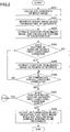
- FIG. 1 is a flowchart illustrating a road surface marking detecting method according to a first embodiment of the present invention. As illustrated in FIG. 1 , the road surface marking detecting method according to the first embodiment of the present invention includes the following steps.
- step S101 an input image of one frame is received.
- the input image of the one frame may be obtained by a camera disposed on a vehicle.
- a contour feature of the input image is analyzed, and a region of interest (ROI) including a road surface marking is extracted from the input image.
- the number of the extracted regions of interest may be one or more.
- the road surface marking to be recognized may be a stop line, namely, a position where a vehicle stops while waiting for a red light.
- the stop line is a horizontal straight line that intersects with a lane line. Note that the present invention is not limited to the above example.
- the road surface marking to be recognized may be a rhombus traffic marking (also referred to as a "pedestrian crossing warning marking"), namely, a rhombus marking painted in the middle of a lane for warning a driver to slow down and pay attention to pedestrians crossing the road using a pedestrian crossing where the vehicle is approaching.
- a rhombus traffic marking also referred to as a "pedestrian crossing warning marking”
- a rhombus marking painted in the middle of a lane for warning a driver to slow down and pay attention to pedestrians crossing the road using a pedestrian crossing where the vehicle is approaching.
- each of the regions of interest is searched for a plurality of endpoints of the road surface marking.
- step S104 it is determined whether the plurality of endpoints of the road surface marking have been detected. Namely, it is determined whether all endpoints for determining the road surface marking have been detected. If the determination result of step S104 is YES, processing proceeds to step S105. In step S105, the road surface marking is determined by joining the plurality of endpoints.
- step S104 determines whether processing for all regions of interest is completed. If the determination result of step S107 is YES, processing is terminated. If the determination result of step S107 is NO, processing returns to step S103, and processing for the next region of interest is continued.
- accurate position information of a road surface marking can be detected by detecting endpoints of the road surface marking.
- FIG. 2 is a flowchart illustrating detailed processing of step S102 in FIG. 1 .
- the step of analyzing the contour feature of the input image and extracting the region of interest including the road surface marking from the input image includes the following steps.
- step S201 gradients of the input image are calculated.
- a binary image is generated based on magnitude of the gradients. For example, a value of a pixel whose magnitude of gradient is greater than a predetermined threshold is set to 1, and a value of a pixel whose magnitude of gradient is less than or equal to the predetermined threshold is set to 0.
- step S203 at least one contour is extracted from the binary image, and a feature of the at least one contour is calculated.
- road surface markings usually have distinctive properties, such as a range of direction, area or aspect ratio of a region corresponding to a road surface marking within a predetermined threshold range
- another contour in the input image that does not relate to the road surface marking to be recognized may be removed by setting an appropriate constraint condition.
- a contour of a stop line can be distinguished from another contour on the road surface such as a pedestrian crossing, by setting a constraint condition that an aspect ratio of a contour is greater than a predetermined threshold.
- a contour of a rhombus marking can be distinguished from another contour on the road surface, by setting a constraint condition that an area of a contour is greater than a predetermined threshold.
- step S204 for each of the extracted contours, it is determined whether the feature of the contour satisfies a first constraint condition.
- step S204 If it is determined in step S204 that the first constraint condition is satisfied, processing proceeds to step S205.
- step S205 the contour is extracted as the region of interest from the binary image.
- step S204 If it is determined in step S204 that the first constraint condition is not satisfied, processing proceeds to step S206.
- step S206 it is determined whether determination for all contours is completed. If the determination result of step S206 is YES, processing proceeds to step S207.
- step S207 it is determined whether a contour whose feature satisfies the first constraint condition exists, namely, it is determined whether the number of contours whose feature satisfies the first constraint condition is greater than zero. If the determination result of step S207 is YES, processing proceeds to step S103 in FIG. 1 to continue subsequent processing. If the determination result of step S207 is NO, processing proceeds to step S208. In step S208, a determination result indicating that the input image does not include the road surface marking to be recognized is output, and processing is terminated.
- step S206 If it is determined in step S206 that determination for all contours is not completed, processing returns to step S204, and determination for a subsequent contour is continued.
- FIG. 3 is a flowchart illustrating detailed processing of step S103 in FIG. 1 .
- the step of searching the region of interest for the plurality of endpoints of the road surface marking includes the following steps.
- step S301 a plurality of initial search points for searching for the plurality of endpoints are determined.
- step S302 the plurality of initial search points are moved along the contour, respectively. Namely, the plurality of initial search points are moved along respective portions of the contour where the respective initial search points are located.
- step S303 moving tracks of the initial search points are analyzed, and in step S304, it is determined whether the initial search points reach the respective endpoints.
- step S304 When it is determined in step S304 that the initial search points reach the respective endpoints, processing proceeds to step S305. In step S305, positions of the respective endpoints are recorded.
- step S304 When it is determined in step S304 that the initial search points do not reach the respective endpoints, processing returns to step S302, and the moving of the initial search points is continued from the current position.
- the road surface marking is a stop line
- the plurality of initial search points includes a left initial search point and a right initial search point
- the plurality of endpoints includes a left endpoint and a right endpoint.
- FIG. 4A is a schematic diagram illustrating projection of a contour in a region of interest on a Y-axis according to a first example of the first embodiment of the present invention
- FIG. 4B is a schematic diagram illustrating the region of interest according to the first example of the first embodiment of the present invention.
- pixel values of points of a contour are 1, and these points of the contour are shown in white in FIG. 4B
- pixel values of points other than the contour are 0, and these points other than the contour are shown in black in FIG. 4B
- pixels whose value is 1 represent a valid region
- pixels whose value is 0 represent an invalid region.
- FIG. 5 is a flowchart illustrating a step of searching the region of interest for a left endpoint and a right endpoint of a stop line according to the first example of the first embodiment of the present invention.
- step S501 a plurality of initial search points for searching for the plurality of endpoints are determined.
- FIGs. 4A and 4B an example of the left endpoint will be described, and processing for the right endpoint is similar to processing for the left endpoint. Specifically, projection of each pixel in the region of interest on a Y-axis is calculated. Note that, only valid pixels can be projected. As illustrated in FIG. 4B , the stop line is a horizontal line. It can be understood that a position of a row in the image that corresponds to a projection peak on the Y-axis where a largest of number of pixels are projected is a position close to the stop line.
- a starting row of the initial search points namely a coordinate on the Y-axis of the initial search points is determined based on a projection position on the Y-axis where a largest of number of pixels are projected.
- a position offset downward from the above peak position is usually set as a starting row of the initial search points, so that the initial search points can be moved upward along a valid contour.
- intersection points between the contour (such as possible lane lines) in the region of interest and the horizontal line are detected, and the number of the intersection points between the possible lane lines and the horizontal line is determined.
- a template matching method may be used as the detection method.
- a starting column of the initial search points is determined based on position distribution of the intersection points. Since the intersection points (connection points) between a lane line and a stop line exist inside a valid contour, column positions of the intersection points have a distinctive feature.
- the detection result of the intersection points may be determined whether the detection result of the intersection points satisfies a constraint condition, for example, it may be determined whether the number of the intersection points is within a certain range, or it may be determined whether the intersection points are distributed on both sides of the region of interest. If the detection result of the intersection points satisfies the constraint condition, the starting row and the starting column of the initial search points, namely the coordinate on the Y-axis and a coordinate on an X-axis of the initial search points are output. If the detection result of the intersection points does not satisfy the constraint condition, it is determined that the region of interest does not include a stop line.
- step S502 the left initial search point and the right initial search point are moved along the contour, respectively.
- a moving direction of the initial search point includes a main direction and an orthogonal direction orthogonal to the main direction.
- the main direction of the left initial search point is a right direction
- the main direction of the right initial search point is a left direction.
- FIG. 6 is a schematic diagram illustrating movement process of a left initial search point. As illustrated in FIG.
- the left initial search point is moved in the upward direction until the left initial search point reaches a pixel whose pixel value is zero, then the left initial search point is moved in the right direction from current position until the left initial search point reaches a pixel whose pixel value is zero.
- step S503 moving tracks of the initial search points are analyzed.
- step S504 it is determined whether the initial search points reach the respective endpoints.
- the step of analyzing the moving tracks of the initial search points and determining whether the initial search points reach the respective endpoints specifically includes the following step. It is determined whether the initial search points reach respective connection points (intersection points) between the contour and a horizontal stop line, by analyzing respective lengths of the moving tracks of the initial search points in the respective main directions.
- the movement amount of each time of moving in the right direction is monitored, and a condition that the movement amount of moving in the right direction is greater than a predetermined threshold is set as a search termination condition. That is to say, when the movement amount in the right direction is greater than the predetermined threshold, it is determined that the left initial search point has reached the left endpoint.
- the step of analyzing the moving tracks of the initial search points and determining whether the initial search points reach the respective endpoints may include (a) determining whether a second constraint condition is satisfied; and (b) continuing determining whether the initial search points reach the respective connection points between the contour and the horizontal stop line, when the second constraint condition is satisfied.
- I(x, y) represents a pixel value of a search point in I
- ⁇ x i and ⁇ y i are offsets of i-th movement of the search point in the main direction and the orthogonal direction orthogonal to the main direction, respectively
- k i represents a search direction.
- an XY coordinate system is defined such that a positive direction of an X-axis is horizontally rightward, a positive direction of a Y-axis is vertically downward, and an origin of the coordinate is located at an upper left corner.
- thr1 is a constraint threshold of the search direction for ensuring that a moving direction approaches to an average direction of previous movements
- thr2 is a constraint threshold of a search length in the main direction
- thr3 is a constraint threshold of a search length in the orthogonal direction.
- the constraint thresholds of the search lengths in the main direction and the orthogonal direction may be constraint conditions for further verification when a search termination condition has been satisfied.
- the constraint thresholds of the search lengths in the main direction and the orthogonal direction may be determination conditions for terminating the search or re-adjusting the initial search points when a search termination condition has not been satisfied.
- step S504 When it is determined in step S504 that the initial search points reach the respective endpoints, processing proceeds to step S505.
- step S505 positions of the respective endpoints are recorded. Specifically, a starting position of the current movement is recorded as a position of the left endpoint.
- the process of determining the right endpoint is similar to the process of determining the left endpoint, and its description is omitted here.
- FIGs. 7A and 7B illustrate a case where an initial search point cannot reach a connection point between a curved lane line and a stop line.
- FIG. 7A illustrates an actual condition of a road surface
- FIG. 7B illustrates a binary image including a contour to be recognized.
- an initial search point cannot reach the connection point between the curved lane line and the stop line by the moving described above.
- FIG. 8 is a flowchart illustrating a step of searching a region of interest for a left endpoint and a right endpoint of a stop line according to a second example of the first embodiment of the present invention.
- step S801 a plurality of initial search points for searching for the plurality of endpoints are determined. Then, in step S802, a left initial search point and a right initial search point are moved along the contour, respectively. Next, moving tracks of the initial search points are analyzed.
- the second example is different from the first example in that the second example further includes steps of optimization and verification of endpoints.
- step S804 it is determined whether endpoint search terminates normally.
- the normal termination means that left and right endpoints are determined when the above search termination condition is satisfied, and this case corresponds to the case described in the first example. If it is determined in step S804 that endpoint search terminates normally, processing proceeds to step S805. In step S805, the left and right endpoints are output.
- step S804 If it is determined in step S804 that endpoint search does not terminate normally, processing proceeds to step S806.
- Abnormal termination of the search includes but is not limited to the following cases. For example, a search point stops at an abnormal point and cannot be further moved in a search process using an initial search point, since a road surface marking is not ideal. Alternatively, only an endpoint on one side can be found, since there is only a lane line of one side in a stop line region.
- an endpoint obtained by the search is recorded in a candidate endpoint set. Specifically, if an initial search point stops at a position and cannot be further moved, the position where the initial search point finally reaches is recorded as a candidate endpoint in a candidate endpoint set. Alternatively, if only a left endpoint corresponding to a left initial search point or a right endpoint corresponding to a right initial search point was found, the left endpoint or the right endpoint is recorded as a candidate endpoint in a candidate endpoint set.
- step S807 a path search is performed based on position of a candidate endpoint in the candidate endpoint set, and an endpoint obtained by the path search is added into the candidate endpoint set.
- FIGs. 9A and 9B illustrate a detailed processing of step S807 in an example of a left candidate endpoint.
- point S_L in the candidate endpoint set is set as a starting point of the path search
- point S_L is moved in a historical path direction until a moving track intersects with a straight line in a horizontal direction at an intersection point
- the intersection point is set as a path search point.
- the historical path direction may be a slope of a previous movement immediately before a current movement, and may also be an average slope of all previous movements.
- the path search point is moved in the main direction, namely, the path search point is moved rightward as illustrated in FIG. 9B , and it is determined whether the path search point reaches an endpoint on a side of the main direction.
- a connection point between a stop line and a lane line is an inside point inside of the lane line, it may be determined whether the path search point reaches a right endpoint, by determining whether a pixel value obtained by moving the path search point rightward is 1, a pixel value obtained by moving the path search point upward is 1 and a pixel value obtained by moving the path search point downward is 1.
- I(x, y) represents a pixel value of a search point in I
- ⁇ x i and ⁇ y i are offsets of i-th movement of the search point in the main direction and the orthogonal direction orthogonal to the main direction, respectively
- k i represents a search direction.
- an XY coordinate system is defined such that a positive direction of an X-axis is horizontally rightward, a positive direction of a Y-axis is vertically downward, and an origin of the coordinate is located at an upper left corner.
- constraint conditions expressed by formula (3) when moving the search point rightward, it is determined whether a pixel value obtained by moving the search point upward by one step is 1, whether a pixel value obtained by moving the search point downward by one step is 0, and whether a pixel value obtained by moving the search point rightward by one step is 1. If the constraint conditions expressed by formula (3) are not satisfied, it is determined that the contour is not a contour to be detected, and processing proceeds to step S106 in FIG. 1 . If the constraint conditions expressed by formula (3) are satisfied, the following moving is continued.
- thr4 is a constraint threshold of the search direction for ensuring that a moving direction approaches to an average direction of previous movements
- thr5 is a constraint threshold of a search length in the main direction
- thr6 is a constraint threshold of a search length in the orthogonal direction.
- the constraint thresholds of the search lengths in the main direction and the orthogonal direction may be constraint conditions for further verification when a search termination condition has been satisfied.
- the constraint thresholds of the search lengths in the main direction and the orthogonal direction may be determination conditions for terminating the search or re-adjusting the initial search points when a search termination condition has not been satisfied.
- Endpoint Q_R1 on the side of the main direction and endpoint Q_L1 on the side of the opposite direction are added into the candidate endpoint set.
- step S808 the candidate endpoints are verified based on a feature extracted from the candidate endpoint set. Specifically, the candidate endpoints in the candidate endpoint set are classified into candidate left endpoints and candidate right endpoints. Each of the candidate left endpoints and each of the candidate right endpoints are combined to form left-and-right point pairs and respective candidate lines. Then, features of the candidate lines, such as slopes, average values of Y-axis coordinates, average values of color, neighborhood differences in color or the like are extracted.
- step S809 it is determined whether the endpoints are endpoints of a stop line. It may be determined whether the endpoints are endpoints of a stop line, by determining whether the features of the candidate lines satisfy a third constraint condition (for example, whether the slopes are within a certain range).
- a third constraint condition for example, whether the slopes are within a certain range.
- step S809 If it is determined in step S809 that the endpoints are endpoints of a stop line, processing proceeds to step S810, and the endpoints of the stop line are output. If it is determined in step S809 that the endpoints are not endpoints of a stop line, processing proceeds to step S811, a determination result indicating that the current region of interest does not include a stop line is output, and processing is terminated.
- the method for detecting a stop line including the process of optimization and verification of endpoints can be applied to various road surface conditions.
- the road surface marking detecting methods are described by taking a stop line as an example.
- the present invention is not limited to these examples.
- the road surface marking may be a rhombus marking for warning a driver to slow down.
- the plurality of initial search points includes a left initial search point and a right initial search point
- the plurality of endpoints includes a left endpoint, a right endpoint and a bottom endpoint. Once the left endpoint, the right endpoint and the bottom endpoint of the rhombus marking are determined, an accurate position of the rhombus marking can be determined.
- FIG. 10 is a schematic diagram illustrating a region of interest according to a third example of the first embodiment of the present invention.
- pixel values of points of a contour are 1, and these points of the contour are shown in white in FIG. 10 ; and pixel values of points other than the contour are 0, and these points other than the contour are shown in black in FIG. 10 .
- pixels whose value is 1 represent a valid region, and pixels whose value is 0 represent an invalid region.
- FIG. 11 is a flowchart illustrating a step of searching a region of interest for a left endpoint and a right endpoint of a rhombus marking according to a third example of the first embodiment of the present invention.
- a left initial search point for searching for the left endpoint and a right initial search point for searching for the right endpoint are determined.
- the left endpoint and the right endpoint are first obtained.
- a starting point as close as possible to a real ending point is selected.
- the contour of the rhombus marking in a gradient image is a dual-rhombus shape. The contour is divided into segments with a zero gradient value by scanning lines crossing the contour, and each of the scanning lines intersects with the contour at two to four intersection points. The longest segment is near a center of the rhombus shape. After a segment with a largest blank position inside the rhombus shape is found, the first and last intersections are obtained as the left and right initial search points.
- step S1102 the left initial search point and the right initial search point are moved along the contour, respectively. Namely, the left initial search point and the right initial search point are moved along respective portions of the contour where the respective initial search points are located.
- the endpoint of the rhombus shape is a corner, and there are three neighborhood pixels with a zero pixel value in the four neighborhood pixels of the endpoint.
- a searching method in an orthogonal direction is proposed to make a starting point reach a real ending point.
- the initial search points are alternately moved in respective main directions and respective orthogonal directions.
- the main directions are left and right directions, and the orthogonal directions are a vertically upward direction and a vertically downward direction.
- the initial search points can be moved along an outer edge and reach an ending point.
- For the right search a starting point is first moved to the outer edge, since intersection points occur on an inner edge.
- step S1103 moving tracks of the initial search points are analyzed.
- step S1104 it is determined whether the initial search points reach the respective endpoints.
- step S1104 When it is determined in step S1104 that the initial search points reach the respective endpoints, processing proceeds to step S1105. In step S1105, positions of the respective endpoints are recorded.
- step S1106 it is determined whether a left endpoint and a right endpoint have been obtained. If the determination result of step S1106 is YES, processing proceeds to step S1107.
- step S1107 a bottom endpoint is obtained based on the left endpoint and the right endpoint. Specifically, after the left and right endpoints are obtained, a search area of the bottom endpoint is narrowed. In the new search area, the number of intersection points between the scanning lines and the contour is calculated. The bottom endpoint can be found based on the scanning line with only one intersection point.
- the endpoints may be further verified to reduce a probability of erroneous determination.
- the three endpoints may be verified based on color information.
- a sampling for pixels near the obtained endpoints that belong to the rhombus shape and to a road region is performed. Then, a similarity of the two sets of pixels is calculated. If the similarity is too high, the endpoint will be abandoned.
- the endpoints are further verified based on relative positions and proportional relationships among the endpoints. Furthermore, the endpoints are also verified based on whether there is a linear path between the left (right) endpoint and the bottom endpoint. A sample is selected by finding an intersection point of scanning lines, and a contour between a lower endpoint and a left endpoint. Then, slopes of lines formed by the endpoints and the sample are calculated. The endpoint is accepted only if all slopes are similar to a lower left direction.
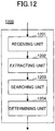
- FIG. 12 is a block diagram illustrating a functional configuration of a road surface marking detecting apparatus according to a second embodiment of the present invention.
- the road surface marking detecting apparatus 1200 according to the second embodiment of the present invention includes a receiving unit 1201, an extracting unit 1202, a searching unit 1203, and a determining unit 1204.
- the receiving unit 1201 receives an input image of one frame.
- the input image of the one frame may be obtained by a camera disposed on a vehicle.
- the extracting unit 1202 analyzes a contour feature of the input image, and extracts a region of interest (ROI) including a road surface marking from the input image.
- the number of the extracted regions of interest may be one or more.
- the road surface marking to be recognized may be a stop line, namely, a position where a vehicle stops while waiting for a red light.
- the stop line is a horizontal straight line that intersects with a lane line. Note that the present invention is not limited to the above example.
- the road surface marking to be recognized may be a rhombus traffic marking (also referred to as a "pedestrian crossing warning marking"), namely, a rhombus marking painted in the middle of a lane for warning a driver to slow down and pay attention to pedestrians crossing the road using a pedestrian crossing where the vehicle is approaching.
- a rhombus traffic marking also referred to as a "pedestrian crossing warning marking”
- a rhombus marking painted in the middle of a lane for warning a driver to slow down and pay attention to pedestrians crossing the road using a pedestrian crossing where the vehicle is approaching.
- the searching unit 1203 searches each of the regions of interest (ROIs) for a plurality of endpoints of the road surface marking.
- the determining unit 1204 determines whether the plurality of endpoints of the road surface marking have been detected.
- accurate position information of a road surface marking can be detected by detecting endpoints of the road surface marking.
- FIG. 13 is a block diagram illustrating a detailed configuration of the extracting unit 1202 in FIG. 12 .
- the extracting unit 1202 includes a gradient calculating unit 1301, a binary image generating unit 1302, a contour extracting unit 1303, a first determining unit 1304, and a ROI (region of interest) extracting unit 1305.
- the gradient calculating unit 1301 calculates gradients of the input image.
- the binary image generating unit 1302 generates a binary image based on magnitude of the gradients. For example, a value of a pixel whose magnitude of gradient is greater than a predetermined threshold is set to 1, and a value of a pixel whose magnitude of gradient is less than or equal to the predetermined threshold is set to 0.
- the contour extracting unit 1303 extracts at least one contour from the binary image, and calculates a feature of the at least one contour.
- road surface markings usually have distinctive properties, such as a range of direction, area or aspect ratio of a region corresponding to a road surface marking within a predetermined threshold range
- another contour in the input image that does not relate to the road surface marking to be recognized may be removed by setting an appropriate constraint condition.
- a contour of a stop line can be distinguished from another contour on the road surface such as a pedestrian crossing, by setting a constraint condition that an aspect ratio of a contour is greater than a predetermined threshold.
- a contour of a rhombus marking can be distinguished from another contour on the road surface, by setting a constraint condition that an area of a contour is greater than a predetermined threshold.
- the first determining unit 1304 determines whether the feature of the contour satisfies a first constraint condition.
- the ROI extracting unit 1305 extracts the contour as the region of interest from the binary image.
- FIG. 14 is a block diagram illustrating a detailed configuration of the searching unit 1203 in FIG. 12 .
- the searching unit 1203 includes an initial search point determining unit 1401, a first moving unit 1402, a second determining unit 1403, and an endpoint recording unit 1404.
- the initial search point determining unit 1401 determines a plurality of initial search points for searching for the plurality of endpoints.
- the first moving unit 1402 moves the plurality of initial search points along the contour, respectively. Namely, the first moving unit 1402 moves the plurality of initial search points along respective portions of the contour where the respective initial search points are located.
- the second determining unit 1403 analyzes moving tracks of the initial search points, and determines whether the initial search points reach the respective endpoints.
- the endpoint recording unit 1404 records positions of the respective endpoints.
- the road surface marking is a stop line
- the plurality of initial search points includes a left initial search point and a right initial search point
- the plurality of endpoints includes a left endpoint and a right endpoint.
- FIG. 15 is a block diagram illustrating a functional configuration of a searching unit in the road surface marking detecting apparatus according to a first example of the second embodiment of the present invention.
- the searching unit according to the first example includes an initial search point determining unit 1501, a first moving unit 1502, a second determining unit 1503, and an endpoint recording unit 1504.
- the initial search point determining unit 1501 includes a projection calculating unit 15011, a starting row determining unit 15012, and a starting column determining unit 15013.
- the projection calculating unit 15011 calculates projection of each pixel in the region of interest on a Y-axis.
- the starting row determining unit 15012 determines a starting row of the initial search points based on a projection position on the Y-axis where a largest of number of pixels are projected.
- the starting column determining unit 15013 draws a horizontal line on the starting row, detects intersection points between the contour in the region of interest and the horizontal line, and determines a starting column of the initial search points based on position distribution of the intersection points.
- an X-axis is a horizontal direction
- the Y-axis is a vertical direction. Since the intersection points (connection points) between a lane line and a stop line exist inside a valid contour, column positions of the intersection points have a distinctive feature. Thus, it may be determined whether the detection result of the intersection points satisfies a constraint condition, for example, it may be determined whether the number of the intersection points is within a certain range, or it may be determined whether the intersection points are distributed on both sides of the region of interest. If the detection result of the intersection points satisfies the constraint condition, the starting row and the starting column of the initial search points, namely the coordinate on the Y-axis and a coordinate on an X-axis of the initial search points are output. If the detection result of the intersection points does not satisfy the constraint condition, it is determined that the region of interest does not include a stop line.
- a constraint condition for example, it may be determined whether the number of the intersection points is within a certain range, or it may be
- a moving direction of the initial search point includes a main direction and an orthogonal direction orthogonal to the main direction.
- the main direction of the left initial search point is a right direction
- the main direction of the right initial search point is a left direction.
- the first moving unit 1502 moves initial search points in an upward direction until the initial search points reach respective pixels whose pixel value is zero, then moves the initial search points in the respective main directions from respective current positions until the initial search points reach respective pixels whose pixel value is zero.
- the above movement process is repeated in a manner that the initial search points are moved in the upward direction and then in the respective main directions. Note that each round of moving includes moving in the upward direction and moving in the respective main directions.
- the second determining unit 1503 determines whether the initial search points reach respective connection points (intersection points) between the contour and a horizontal stop line, by analyzing respective lengths of the moving tracks of the initial search points in the respective main directions.
- the movement amount of each time of moving in the right direction is monitored, and a condition that the movement amount of moving in the right direction is greater than a predetermined threshold is set as a search termination condition. That is to say, when the movement amount in the right direction is greater than the predetermined threshold, it is determined that the left initial search point has reached the left endpoint.
- the second determining unit 1503 may (a) determines whether a second constraint condition is satisfied; and (b) continues determining whether the initial search points reach the respective connection points between the contour and the horizontal stop line, when the second constraint condition is satisfied.
- I(x, y) represents a pixel value of a search point in I
- ⁇ x i and ⁇ y i are offsets of i-th movement of the search point in the main direction and the orthogonal direction orthogonal to the main direction, respectively
- k i represents a search direction.
- an XY coordinate system is defined such that a positive direction of an X-axis is horizontally rightward, a positive direction of a Y-axis is vertically downward, and an origin of the coordinate is located at an upper left corner.
- thr1 is a constraint threshold of the search direction for ensuring that a moving direction approaches to an average direction of previous movements
- thr2 is a constraint threshold of a search length in the main direction
- thr3 is a constraint threshold of a search length in the orthogonal direction.
- the constraint thresholds of the search lengths in the main direction and the orthogonal direction may be constraint conditions for further verification when a search termination condition has been satisfied.
- the constraint thresholds of the search lengths in the main direction and the orthogonal direction may be determination conditions for terminating the search or re-adjusting the initial search points when a search termination condition has not been satisfied.
- the above first example is a case where the condition of the road surface marking is ideal.
- the left and right initial search points can reach the positions of the left and right endpoints, respectively.
- the apparatus for searching for endpoints according to a second example can be applied to a case where the road surface marking is not ideal.
- FIG. 16 is a block diagram illustrating a detailed configuration of the searching unit 1203 in the road surface marking detecting apparatus according to a second example of the second embodiment of the present invention.
- the searching unit 1203 according to the second example includes an initial search point determining unit 1601, a first moving unit 1602, a second determining unit 1603, and an endpoint recording unit 1604.
- the second example is different from the first example in that the searching unit 1203 according to the second example further includes a candidate endpoint recording unit 1605, a candidate endpoint set adding unit 1606, and a verifying unit 1607.
- the candidate endpoint recording unit 1605 records an endpoint obtained by the search in a candidate endpoint set, when endpoint search does not terminate normally.
- the normal termination means that left and right endpoints are determined when the above search termination condition is satisfied. This case corresponds to the case described in the first example.
- Abnormal termination of the search includes but is not limited to the following cases. For example, a search point stops at an abnormal point and cannot be further moved in a search process using an initial search point, since a road surface marking is not ideal. Alternatively, only an endpoint on one side can be found, since there is only a lane line of one side in a stop line region.
- the position where the initial search point finally reaches is recorded as a candidate endpoint in a candidate endpoint set.
- the left endpoint or the right endpoint is recorded as a candidate endpoint in a candidate endpoint set.
- the candidate endpoint set adding unit 1606 performs a path search based on position of a candidate endpoint in the candidate endpoint set, and adds an endpoint obtained by the path search into the candidate endpoint set.
- the candidate endpoint set adding unit 1606 includes a path search point determining unit 16061, a second moving unit 16062, a third determining unit 16063, and an adding unit 16064.
- the path search point determining unit 16061 movies the candidate endpoint in the candidate endpoint set serving as a starting point of the path search in a historical path direction, until a moving track intersects with a straight line in a horizontal direction at an intersection point serving as a path search point.
- the second moving unit 16062 moves the path search point in the main direction.
- the third determining unit 16063 determines whether the path search point reaches an endpoint on a side of the main direction.
- the second moving unit 16062 moves the endpoint in an opposite direction opposite to the main direction to perform a search when the path search point reaches the endpoint on the side of the main direction, and the third determining unit 16063 determines whether the endpoint reaches an endpoint on a side of the opposite direction.
- the adding unit 16064 adds the endpoint on the side of the main direction and the endpoint on the side of the opposite direction into the candidate endpoint set.
- FIGs. 9A and 9B illustrate a detailed processing of step S807 in an example of a left candidate endpoint.
- point S_L in the candidate endpoint set is set as a starting point of the path search
- point S_L is moved in a historical path direction until a moving track intersects with a straight line in a horizontal direction at an intersection point
- the intersection point is set as a path search point.
- the historical path direction may be a slope of a previous movement immediately before a current movement, and may also be an average slope of all previous movements.
- the path search point is moved in the main direction, namely, the path search point is moved rightward as illustrated in FIG. 9B , and it is determined whether the path search point reaches an endpoint on a side of the main direction.
- a connection point between a stop line and a lane line is an inside point inside of the lane line, it may be determined whether the path search point reaches a right endpoint, by determining whether a pixel value obtained by moving the path search point rightward is 1, a pixel value obtained by moving the path search point upward is 1 and a pixel value obtained by moving the path search point downward is 1.
- I(x, y) represents a pixel value of a search point in I
- ⁇ x i and ⁇ y i are offsets of i-th movement of the search point in the main direction and the orthogonal direction orthogonal to the main direction, respectively
- k i represents a search direction.
- an XY coordinate system is defined such that a positive direction of an X-axis is horizontally rightward, a positive direction of a Y-axis is vertically downward, and an origin of the coordinate is located at an upper left corner.
- constraint conditions expressed by formula (3) when moving the search point rightward, it is determined whether a pixel value obtained by moving the search point upward by one step is 1, whether a pixel value obtained by moving the search point downward by one step is 0, and whether a pixel value obtained by moving the search point rightward by one step is 1. If the constraint conditions expressed by formula (3) are not satisfied, it is determined that the contour is not a contour to be detected, and processing proceeds to step S106 in FIG. 1 . If the constraint conditions expressed by formula (3) are satisfied, the following moving is continued.
- thr4 is a constraint threshold of the search direction for ensuring that a moving direction approaches to an average direction of previous movements
- thr5 is a constraint threshold of a search length in the main direction
- thr6 is a constraint threshold of a search length in the orthogonal direction.
- the constraint thresholds of the search lengths in the main direction and the orthogonal direction may be constraint conditions for further verification when a search termination condition has been satisfied.
- the constraint thresholds of the search lengths in the main direction and the orthogonal direction may be determination conditions for terminating the search or re-adjusting the initial search points when a search termination condition has not been satisfied.
- the endpoint on the side of the main direction namely point Q_R1 in FIG. 9B is obtained.
- endpoint Q_R1 is moved in an opposite direction opposite to the main direction to perform a search, it is determined whether the endpoint reaches an endpoint on a side of the opposite direction, and an opposite endpoint, namely point Q_L1 in FIG. 9B is obtained.
- the adding unit 16064 adds endpoint Q_R1 on the side of the main direction and endpoint Q_L1 on the side of the opposite direction into the candidate endpoint set.
- the verifying unit 1607 verifies whether the candidate endpoints in the candidate endpoint set are the endpoints of the stop line based on a feature extracted from the candidate endpoint set.
- the verifying unit 1607 includes a combining unit 16071, a fourth determining unit 16072, and an output unit 16073.
- the combining unit 16071 classifies the candidate endpoints in the candidate endpoint set into candidate left endpoints and candidate right endpoints, and combines each of the candidate left endpoints and each of the candidate right endpoints to form left-and-right point pairs and respective candidate lines.
- the fourth determining unit 16072 extracts features of the candidate lines, such as slopes, average values of Y-axis coordinates, average values of color, neighborhood differences in color or the like, and determines whether extracted features of the candidate lines satisfy a third constraint condition (for example, whether the slopes are within a certain range).
- a third constraint condition for example, whether the slopes are within a certain range.
- the output unit 16073 determines the candidate line whose extracted feature satisfies the third constraint condition as the stop line, and outputs endpoints of the determined candidate line.
- the apparatus for detecting a stop line using the process of optimization and verification of endpoints can be applied to various road surface conditions.
- the road surface marking detecting apparatuses are described by taking a stop line as an example.
- the present invention is not limited to these examples.
- the road surface marking may be a rhombus marking for warning a driver to slow down.
- the plurality of initial search points includes a left initial search point and a right initial search point
- the plurality of endpoints includes a left endpoint, a right endpoint and a bottom endpoint. Once the left endpoint, the right endpoint and the bottom endpoint of the rhombus marking are determined, an accurate position of the rhombus marking can be determined.
- FIG. 17 is a block diagram illustrating a detailed configuration of a searching unit 1203 in the road surface marking detecting apparatus according to a third example of the second embodiment of the present invention.
- the searching unit 1203 according to the third example includes an initial search point determining unit 1701, a first moving unit 1702, a second determining unit 1703, an endpoint recording unit 1704, and a bottom endpoint determining unit 1705.
- the initial search point determining unit 1701 determines a left initial search point for searching for the left endpoint and a right initial search point for searching for the right endpoint. As important information that simplifies the calculation for searching the bottom endpoint, the left endpoint and the right endpoint are first obtained by the initial search point determining unit 1701. In order to perform the search more efficiently, a starting point as close as possible to a real ending point is selected.
- the contour of the rhombus marking in a gradient image is a dual-rhombus shape. The contour is divided into segments with a zero gradient value by scanning lines crossing the contour, and each of the scanning lines intersects with the contour at two to four intersection points. The longest segment is near a center of the rhombus shape. After a segment with a largest blank position inside the rhombus shape is found, the first and last intersections are obtained as the left and right initial search points.
- the first moving unit 1702 moves the left initial search point and the right initial search point along the contour, respectively. Namely, the first moving unit 1702 moves the left initial search point and the right initial search point along respective portions of the contour where the respective initial search points are located.
- the endpoint of the rhombus shape is a corner, and there are three neighborhood pixels with a zero pixel value in the four neighborhood pixels of the endpoint.
- a searching method in an orthogonal direction is proposed to make a starting point reach a real ending point.
- the initial search points are alternately moved in respective main directions and respective orthogonal directions.
- the main directions are left and right directions, and the orthogonal directions are a vertically upward direction and a vertically downward direction.
- the initial search points can be moved along an outer edge and reach an ending point.
- For the right search a starting point is first moved to the outer edge, since intersection points occur on an inner edge.
- the second determining unit 1703 analyzes moving tracks of the initial search points, and determines whether the initial search points reach respective endpoints.
- the endpoint recording unit 1704 records positions of the respective endpoints.
- the bottom endpoint determining unit 1705 obtains bottom endpoint based on the left endpoint and the right endpoint. Specifically, after the left and right endpoints are obtained, a search area of the bottom endpoint is narrowed. In the new search area, the number of intersection points between the scanning lines and the contour is calculated. The bottom endpoint can be found based on the scanning line with only one intersection point.
- the searching unit according to the third example may further include a verifying unit for verifying the endpoints to reduce a probability of erroneous determination.
- the three endpoints may be verified based on color information.
- a sampling for pixels near the obtained endpoints that belong to the rhombus shape and to a road region is performed. Then, a similarity of the two sets of pixels is calculated. If the similarity is too high, the endpoint will be abandoned.
- the endpoints are further verified based on relative positions and proportional relationships among the endpoints. Furthermore, the endpoints are also verified based on whether there is a linear path between the left (right) endpoint and the bottom endpoint. A sample is selected by finding an intersection point of scanning lines, and a contour between a lower endpoint and a left endpoint. Then, slopes of lines formed by the endpoints and the sample are calculated. The endpoint is accepted only if all slopes are similar to a lower left direction.
- FIG. 18 is a block diagram illustrating a hardware configuration of a road surface marking detecting device according to a third embodiment of the present invention.
- the road surface marking detecting device according to a third embodiment of the present invention includes at least one processor 1801 and a memory 1802 for storing computer-readable instructions.
- the computer-executable instructions When executed by the processor 1801, the computer-executable instructions cause the processor 1801 to carry out the road surface marking detecting method described in the above first embodiment of the present invention.
- FIG. 19 is a schematic diagram illustrating a non-transitory computer-readable recording medium according to a fourth embodiment of the present invention.
- the non-transitory computer-readable recording medium 1900 has computer-executable instructions 1901 for execution by at least one processor.
- the computer-executable instructions 1901 When executed, the computer-executable instructions 1901 cause the at least one processor to carry out the road surface marking detecting method described in the above first embodiment of the present invention.
- the units, apparatuses, devices, steps, methods and system are just examples, the connection, placement and configuration illustrated in the block diagrams related to the present invention are not limited to these examples, and the units, apparatuses, devices, steps, methods and system may be connected, placed or configured in any way.
- the terms “comprise”, “include” and “have” are open-form terms, which mean and may be changed into “include and is not limited to”.
- the terms “or” and “and” mean and may be changed into “and/or”, unless the context is clearly not applicable.
- the term “such as” means and may be changed to "such as, but not limited to”.
- Steps of the above method may be performed in the time order, however the performing sequence is not limited to the time order. Any steps may be performed in parallel or independently.
- a computer software product according to the embodiment may be stored in a computer-readable medium as one or more commands.
- the recording medium may be any real medium that can be accessed by a computer (such as a personal computer, a server, a network device or the like).
- a computer-readable medium includes a RAM, a ROM, an EEPROM, a CD-ROM or other laser discs, a magnetic disk or other magnetic memory, or any other real media that carry or store commands, data or program codes and are accessed by the computer.
Landscapes
- Engineering & Computer Science (AREA)
- Physics & Mathematics (AREA)
- General Physics & Mathematics (AREA)
- Multimedia (AREA)
- Theoretical Computer Science (AREA)
- Computer Vision & Pattern Recognition (AREA)
- Image Analysis (AREA)
- Image Processing (AREA)
Applications Claiming Priority (1)
| Application Number | Priority Date | Filing Date | Title |
|---|---|---|---|
| CN201810095668.7A CN110096934A (zh) | 2018-01-31 | 2018-01-31 | 路面标识检测方法和设备 |
Publications (1)
| Publication Number | Publication Date |
|---|---|
| EP3522073A1 true EP3522073A1 (fr) | 2019-08-07 |
Family
ID=65036643
Family Applications (1)
| Application Number | Title | Priority Date | Filing Date |
|---|---|---|---|
| EP19152235.8A Withdrawn EP3522073A1 (fr) | 2018-01-31 | 2019-01-17 | Procédé et appareil de détection de marquage de surface de route |
Country Status (2)
| Country | Link |
|---|---|
| EP (1) | EP3522073A1 (fr) |
| CN (1) | CN110096934A (fr) |
Cited By (3)
| Publication number | Priority date | Publication date | Assignee | Title |
|---|---|---|---|---|
| CN111681300A (zh) * | 2020-06-02 | 2020-09-18 | 西安电子科技大学 | 轮廓素描线组成的目标区域获取方法 |
| CN112419357A (zh) * | 2020-11-18 | 2021-02-26 | 方正株式(武汉)科技开发有限公司 | 一种生成图像实体轮廓一笔画路径的方法及系统 |
| WO2022149046A1 (fr) * | 2021-01-11 | 2022-07-14 | Mobileye Vision Technologies Ltd. | Systèmes et procédés de surveillance de la qualité d'une marque de voie |
-
2018
- 2018-01-31 CN CN201810095668.7A patent/CN110096934A/zh not_active Withdrawn
-
2019
- 2019-01-17 EP EP19152235.8A patent/EP3522073A1/fr not_active Withdrawn
Non-Patent Citations (2)
| Title |
|---|
| DUCHOW C: "A marking-based, Flexible approach to intersection detection", PROCEEDINGS / 2005 IEEE COMPUTER SOCIETY CONFERENCE ON COMPUTER VISION AND PATTERN RECOGNITION, CVPR 2005 : [20 - 25 JUNE 2005, SAN DIEGO, CA], IEEE, PISCATAWAY, NJ, USA, 25 June 2005 (2005-06-25), pages 60, XP031259700, ISBN: 978-0-7695-2372-9 * |
| ZHAO LI ET AL: "Road markings extraction based on threshold segmentation", FUZZY SYSTEMS AND KNOWLEDGE DISCOVERY (FSKD), 2012 9TH INTERNATIONAL CONFERENCE ON, IEEE, 29 May 2012 (2012-05-29), pages 1924 - 1928, XP032455998, ISBN: 978-1-4673-0025-4, DOI: 10.1109/FSKD.2012.6234167 * |
Cited By (5)
| Publication number | Priority date | Publication date | Assignee | Title |
|---|---|---|---|---|
| CN111681300A (zh) * | 2020-06-02 | 2020-09-18 | 西安电子科技大学 | 轮廓素描线组成的目标区域获取方法 |
| CN111681300B (zh) * | 2020-06-02 | 2023-03-10 | 西安电子科技大学 | 轮廓素描线组成的目标区域获取方法 |
| CN112419357A (zh) * | 2020-11-18 | 2021-02-26 | 方正株式(武汉)科技开发有限公司 | 一种生成图像实体轮廓一笔画路径的方法及系统 |
| CN112419357B (zh) * | 2020-11-18 | 2023-06-30 | 方正株式(武汉)科技开发有限公司 | 一种生成图像实体轮廓一笔画路径的方法及系统 |
| WO2022149046A1 (fr) * | 2021-01-11 | 2022-07-14 | Mobileye Vision Technologies Ltd. | Systèmes et procédés de surveillance de la qualité d'une marque de voie |
Also Published As
| Publication number | Publication date |
|---|---|
| CN110096934A (zh) | 2019-08-06 |
Similar Documents
| Publication | Publication Date | Title |
|---|---|---|
| US10521676B2 (en) | Lane detection device, lane departure determination device, lane detection method and lane departure determination method | |
| JP3169483B2 (ja) | 道路環境認識装置 | |
| JP5407898B2 (ja) | 対象物検出装置及びプログラム | |
| JP6193819B2 (ja) | 走行区画線認識装置 | |
| US7327855B1 (en) | Vision-based highway overhead structure detection system | |
| CN102663356B (zh) | 车道线提取及偏离预警方法 | |
| CN103116748B (zh) | 基于路面标识识别违规驾驶行为的方法及系统 | |
| EP3258214A1 (fr) | Dispositif de détection d'objet | |
| CN111103594A (zh) | 车辆中区分虚假目标的装置和方法及包括其的车辆 | |
| JP5397157B2 (ja) | 車両追跡システム、車両追跡方法および車両追跡プログラム | |
| US20100110193A1 (en) | Lane recognition device, vehicle, lane recognition method, and lane recognition program | |
| CN102997900A (zh) | 外界识别方法、装置以及车辆系统 | |
| US20150154460A1 (en) | Image processing apparatus and image processing method | |
| JPH09319872A (ja) | 道路白線検出装置と曲率半径計算装置とナビゲーション装置 | |
| JP2010160777A (ja) | 地図生成装置、走路推定装置、移動可能領域推定装置、及びプログラム | |
| WO2017130640A1 (fr) | Dispositif de traitement d'image, dispositif d'imagerie, système de commande d'appareil d'entité mobile, procédé de traitement d'image, et programme | |
| WO2014181386A1 (fr) | Dispositif d'évaluation de véhicule | |
| JP2012150595A (ja) | 一時停止線検出装置及びプログラム | |
| JP2014059655A (ja) | 道路状況監視装置、及び道路状況監視方法 | |
| WO2021093335A1 (fr) | Procédé de marquage automatique d'intention de changement de voie en fonction de données de trajectoire à bruit élevé d'un véhicule | |
| CN115704908A (zh) | 利用激光雷达传感器的对象检测方法和对象跟踪装置 | |
| JP2006140636A (ja) | 障害物検出装置および方法 | |
| JP2002334330A (ja) | 車両認識装置 | |
| KR20200058272A (ko) | 도로 주행 영상의 전처리를 통한 도로 주행 상황 제공 방법 및 시스템 | |
| JP2014194698A (ja) | 道路端検出システム、方法およびプログラム |
Legal Events
| Date | Code | Title | Description |
|---|---|---|---|
| PUAI | Public reference made under article 153(3) epc to a published international application that has entered the european phase |
Free format text: ORIGINAL CODE: 0009012 |
|
| STAA | Information on the status of an ep patent application or granted ep patent |
Free format text: STATUS: REQUEST FOR EXAMINATION WAS MADE |
|
| 17P | Request for examination filed |
Effective date: 20190117 |
|
| AK | Designated contracting states |
Kind code of ref document: A1 Designated state(s): AL AT BE BG CH CY CZ DE DK EE ES FI FR GB GR HR HU IE IS IT LI LT LU LV MC MK MT NL NO PL PT RO RS SE SI SK SM TR |
|
| AX | Request for extension of the european patent |
Extension state: BA ME |
|
| STAA | Information on the status of an ep patent application or granted ep patent |
Free format text: STATUS: EXAMINATION IS IN PROGRESS |
|
| 17Q | First examination report despatched |
Effective date: 20200424 |
|
| STAA | Information on the status of an ep patent application or granted ep patent |
Free format text: STATUS: THE APPLICATION IS DEEMED TO BE WITHDRAWN |
|
| 18D | Application deemed to be withdrawn |
Effective date: 20220406 |