EP3522201A1 - Autosampler - Google Patents
Autosampler Download PDFInfo
- Publication number
- EP3522201A1 EP3522201A1 EP18155008.8A EP18155008A EP3522201A1 EP 3522201 A1 EP3522201 A1 EP 3522201A1 EP 18155008 A EP18155008 A EP 18155008A EP 3522201 A1 EP3522201 A1 EP 3522201A1
- Authority
- EP
- European Patent Office
- Prior art keywords
- connector
- containers
- autosampler
- sample
- ions
- Prior art date
- Legal status (The legal status is an assumption and is not a legal conclusion. Google has not performed a legal analysis and makes no representation as to the accuracy of the status listed.)
- Granted
Links
Images
Classifications
-
- H—ELECTRICITY
- H01—ELECTRIC ELEMENTS
- H01J—ELECTRIC DISCHARGE TUBES OR DISCHARGE LAMPS
- H01J49/00—Particle spectrometers or separator tubes
- H01J49/02—Details
- H01J49/04—Arrangements for introducing or extracting samples to be analysed, e.g. vacuum locks; Arrangements for external adjustment of electron- or ion-optical components
- H01J49/0409—Sample holders or containers
- H01J49/0413—Sample holders or containers for automated handling
-
- H—ELECTRICITY
- H01—ELECTRIC ELEMENTS
- H01J—ELECTRIC DISCHARGE TUBES OR DISCHARGE LAMPS
- H01J49/00—Particle spectrometers or separator tubes
- H01J49/02—Details
- H01J49/04—Arrangements for introducing or extracting samples to be analysed, e.g. vacuum locks; Arrangements for external adjustment of electron- or ion-optical components
- H01J49/0422—Arrangements for introducing or extracting samples to be analysed, e.g. vacuum locks; Arrangements for external adjustment of electron- or ion-optical components for gaseous samples
Definitions
- the invention relates to an autosampler for obtaining mass spectra from a plurality of fluid samples, in particular gaseous samples.
- This autosampler comprises a plurality of containers comprising sample sources providing the samples, wherein each one of the containers provides a docking port for being connected with a connector for enabling access to an inside of the respective container via the connector when the connector is connected to the respective docking port in order to obtain the respective sample from the respective container via the connector, wherein the connector is connectable to and detachable from each docking port.
- the autosampler comprises an ionisation source for ionising at least a part of the samples to ions, wherein the ionisation source is fluidly coupled to the connector for receiving the samples from the containers via the connector.
- the autosampler comprises a mass analyser for obtaining the mass spectra from the ions, the mass analyser being fluidly coupled to the ionisation source for receiving the ions from the ionisation source for obtaining the mass spectra from the ions.
- Autosamplers are devices which automatically collect and analyse samples. Autosamplers for obtaining mass spectra from a plurality of fluid samples pertaining to the technical field initially mentioned are known. They commonly have the disadvantage that during the transfer of the samples from the containers to the ionisation source and subsequently to the mass analyser, an intermixture of the different samples occurs, contaminating the obtained mass spectra which downgrades their significance.
- the ionisation source is moveable with the connector within the autosampler sequentially to each one of the plurality of the containers for connecting the connector to the docking port of the respective container for collecting the sample from the respective container for ionising at least a part of the sample to ions and obtaining the mass spectra from the ions.
- the samples are fluid samples.
- the samples can be liquid samples or gaseous samples. These samples originate from sample sources in the containers.
- each one of the containers comprises one of the sample sources.
- the sample sources may for example each be a liquid.
- each sample may be a part of the sample source.
- the samples may be vaporised liquid and thus gaseous samples.
- headspace sampling may for example be employed for obtaining the samples.
- the sample sources can each be a gas, too.
- the sample sources can be microorganisms, plants, or objects like wood, fabrics, drugs or pills or any solid stored in the containers.
- the samples may for example be gas which is degased by the respective sample source in the respective container.
- the containers may for example be jars, boxes, vials or any other container capable of containing a sample source.
- the containers may each be a chemical reactor or any other type of reactor or a material emission climate chamber.
- each one of the containers provides a docking port for being connected with a connector for enabling access to an inside of the respective container via the connector when the connector is connected to the respective docking port in order to obtain the respective sample from the respective container via the connector.
- the docking port may be a port located at the respective container or may be a port on a tube fluidly coupling the port to the inside of the respective container.
- the ionisation source is for ionising at least a part of said samples to ions.
- the ionisation source is for ionising at least a part of each one of the samples to ions.
- the ionisation source is for ionising at least a part of at least one of the samples to ions.
- the method according to the invention for obtaining mass spectra from a plurality of fluid samples with an autosampler comprises keeping sample sources providing the samples in a plurality of containers, wherein each one of the containers provides a docking port for being connected with a connector for enabling access to an inside of the respective container via the connector when the connector is connected to the respective docking port in order to obtain the respective sample from the respective container via the connector, wherein the connector is connectable to and detachable from each docking port.
- the method according to the invention furthermore comprises sequentially sampling the containers by:
- the connector is detached from the docking port of the respective container.
- each time one of the containers is sampled the respective sample is transferred during a time from 1 s to 60 s from the respective container to the ionisation source.
- the respective sample can be transferred during a time shorter than 1 s or during a time longer than 60 s, too.
- each time one of the containers is sampled the respective sample is transferred during a time of 30 minutes or even more.
- detaching the connector from the docking port of one of the containers, moving the ionisation source and the connector within the autosampler to the next one of the containers and connecting the connector to this next one of the containers takes a time from 1 s to 30 seconds. Alternatively however, this may take a shorter or a longer time.
- mass spectra are obtained repeatedly when one of the containers is sampled.
- one or more mass spectrum is obtained.
- up to 10 6 or more mass spectra are obtained per sampling of one container.
- mass spectra are obtained repeatedly as well when none of the containers is sampled. This has the advantage that any leftovers in the system from samples originating from containers previously sampled can be identified such that contaminations in mass spectra obtained from containers which are later sampled can be identified.
- mass spectra can be obtained repeatedly only when one of the containers is sampled.
- Both the autosampler and the method according to the invention have the advantage that more accurate mass spectra of the samples can be obtained.
- One reason for this advantage is that due to the moving ionisation source, the sample sources are not required to be moved. Thus, the sample sources can be kept undisturbed which reduces interference factors which could distort the samples.
- a length of the sample path along which the samples are passed when being transferred from the respective container to the ionisation source can be reduced.
- an absolute number of remains of samples along the sample path is reduced due to the reduced length of the sample path, leading to less intermixtures of different samples as the samples are passed from the containers to the ionisation source.
- the connector can be connected to one of the docking ports at a time only.
- the connector can maximally be connected to two or three or even more docking ports at a time.
- the connector can be constructed to be connectable to 25 docking ports at a time.
- a tray of 5 x 5 containers can be sampled at a time.
- the ionisation source is moveable together with the connector within the autosampler to each one of the plurality of the containers for collecting the samples for connecting the connector to the docking port of the respective container for collecting the sample from the respective container for ionising at least a part of the sample to ions and obtaining the mass spectra from the ions.
- the ionisation source and the connector are preferably moveable at a fixed distance from each other within the autosampler when the ionisation source is moved from one container to another container for collecting the samples.
- the connector is preferably arranged at a fixed position with respect to the ionisation source.
- the connector is moveable with respect to the ionisation source.
- the ionisation source and the connector can be moveable at a fixed distance from each other within the autosampler when the ionisation source is moved from one container to another container for collecting the samples. Then, once the ionisation source is positioned correctly with respect to the respective container, the connector is moveable relative to the ionisation source for getting connected to the docking port of the respective container.
- the connector may be moveable relative to the ionisation source already during movement of the ionisation source with respect to the containers. In this case however, the connector and the ionisation source both move with respect to the containers when the ionisation source is moved with the connector from one container to another container for collecting the samples.
- the autosampler comprises a driving unit for actuating movement of the ionisation source with the connector within the autosampler sequentially to each one of the plurality of the containers for connecting the connector to the docking port of the respective container for collecting the sample from the respective container for ionising at least a part of the sample to ions and obtaining the mass spectra from said ions.
- the driving unit can comprise an electric motor, a pneumatic system or the like for actuating the movement of the ionisation source with the connector.
- the ionisation source is a chemical ionisation source.
- the ionisation source is a proton transfer reaction (PTR) ionisation source.
- the ionisation source is a charge transfer ionisation source.
- the ionisation source may be a different type of ionisation source.
- the ionisation source is an electrospray ionisation source, corona discharge ionisation source, an x-ray ionisation source, a plasma ionisation source, radioactive ionisation source.
- An electrospray ionisation source is particular advantageous in case the samples are liquid samples because an electrospray ionisation source readily generates ions from a liquid.
- the mass analyser is a time-of-flight mass analyser.
- the mass analyser can be a different type of mass analyser like for example a quadrupole mass analyser.
- the mass analyser is moveable together with the ionisation source within the autosampler sequentially to each one of the plurality of the containers for connecting the connector to the docking port of the respective container for collecting the samples from the respective container for ionising at least a part of the samples to ions and for obtaining the mass spectra from the ions.
- the autosampler advantageously comprises a driving unit for actuating movement of the mass analyser together with the ionisation source within the autosampler sequentially to each one of the plurality of the containers for connecting the connector to the docking port of the respective container for collecting the sample from the respective container for ionising at least a part of the samples to ions and for obtaining the mass spectra from the ions.
- This driving unit can be the same driving unit as or a different driving unit than the driving unit for actuating the movement of the ionisation source with the connector within the autosampler sequentially to each one of the plurality of the containers for connecting the connector to the docking port of the respective container for collecting the sample from the respective container for ionising at least a part of the sample to ions and obtaining the mass spectra from the ions.
- the mass analyser is moveable at a fixed distance from the ionisation source within the autosampler sequentially to each one of the plurality of the containers for connecting the connector to the docking port of the respective container for collecting the sample from the respective container for ionising at least a part of the sample to ions and obtaining the mass spectra from the ions.
- the mass analyser is moveable at a fixed position with respect to the ionisation source together with the ionisation source within the autosampler sequentially to each one of the plurality of the containers for connecting the connector to the docking port of the respective container for collecting the sample from the respective container for ionising at least a part of the sample to ions and obtaining the mass spectra from the ions.
- the mass analyser is moveable with the ionisation source at a varying distance from the ionisation source within the autosampler sequentially to each one of the plurality of the containers for connecting the connector to the docking port of the respective container for collecting the sample from the respective container for ionising at least a part of the sample to ions and obtaining the mass spectra from the ions.
- the mass analyser is not moveable with the ionisation source within the autosampler sequentially to each one of the plurality of the containers for connecting the connector to the docking port of the respective container for collecting the sample from the respective container for ionising at least a part of the sample to ions and obtaining the mass spectra from the ions.
- the mass analyser can for example be arranged at a fixed position within the autosampler.
- the autosampler comprises an ion mobility spectrometer.
- the ion mobility spectrometer is preferably arranged to receive the ions from the ionisation source and preferably provides the ions to the mass analyser.
- the mass analyser may be incorporated into the ion mobility spectrometer.
- the autosampler comprises an ion mobility spectrometer
- the autosampler comprises a drifting region for separating ions according to their drifting time, wherein the ions are insertable into the drifting region in a pulsed manner at a fist end of the drifting region, wherein the mass analyser is arranged at a second end of the drifting region for receiving the ions having passed the drifting region and for determining a time the ions required for passing the drifting region.
- the autosampler goes without an ion mobility spectrometer.
- each one of the plurality of the containers provides an inside with a volume which is in a range from 0.1 l to 10 l, preferably in a range from 0.1 l to 5 l, particular preferably in a range from 0.1 l to 2 l, and most preferably in a range from 0.1 l to 1 l.
- a volume which is in a range from 0.1 l to 10 l, preferably in a range from 0.1 l to 5 l, particular preferably in a range from 0.1 l to 2 l, and most preferably in a range from 0.1 l to 1 l.
- each one of the plurality of the containers provides an inside with a volume which is smaller than 0.1 l or larger than 10 l are possible.
- the autosampler comprises at least five containers and maximally 500, particular preferably maximally 200, more preferably 100, most preferably 50 containers.
- the autosampler may comprise less than five containers like four, three or two containers or more than 500 containers.
- At least two containers are identical.
- at least five containers are identical.
- the containers differ from each other.
- the docking ports of the containers are identical.
- the docking ports of the containers are constructed the same way.
- This has the advantage that a length of the resulting sample transfer line is the same for all samples.
- mass spectra obtained from different samples originating from different sample sources can more easily be compared.
- the docking ports of the containers differ from each other.
- the samples are gaseous samples.
- the samples are liquid samples. In yet another preferred variant, the samples are samples in the form of aerosol particles.
- the autosampler comprises a heating unit for heating the sample sources in the containers.
- the heating unit is adapted for heating all containers with their content.
- the heating unit may be adapted to heat all containers together or to heat each container with its content individually and thus to an individual temperature, wherein the individual temperatures of the containers can differ from container to container.
- each container comprises a heating unit.
- the content of each container can be heated to an individual temperature. This has the advantage that the individual temperatures within the containers be tuned very subtle.
- the autosampler may go without such a heating unit.
- Such an alternative has the advantage that the autosampler can be constructed simpler.
- the autosampler may also comprise a source of electromagnetic radiation like for example visible light for irradiating the sample sources.
- the heating unit is preferably adapted for causing thermal desorption for providing the samples.
- the samples can be obtained more efficiently.
- the sample sources are liquid sample sources.
- the samples may be obtained by thermal desorption supported by heat.
- the gaseous samples may be obtained by bubbling a gas through the liquid sample sources. This gas may for example be a purging gas.
- the gaseous samples may be obtained by irradiating laser light on the sample sources.
- each sample is preferably transferable along sample path from the respective container where the respective sample is stored via the docking port of the respective container and via the connector connected to the docking port of the respective container to the ionisation source.
- a sample path is provided from the inside of the respective container via the docking port of the respective container and the connector connected to the respective docking port to the ionisation source for transferring the sample from the respective container to the ionisation source.
- the autosampler provides a sample path heating unit for heating these sample paths. This has the advantage that parts of the samples are less likely to stick to any wall or valve along the respective sample path. Thus, less remains of the samples remain in the sample paths which reduces contamination of later samples passing through the sample paths at a later time. Consequently, this has the advantage that less falsified mass spectra can be obtained.
- the autosampler may go without such a sample path heating unit.
- the autosampler comprises a control unit for controlling said autosampler.
- the control unit can be one physical unit or may comprise more than one physical units.
- Such a physical unit may for example be an electronic control device like an electronic controller or a computer.
- the control unit comprises more than one physical unit, the physical units are preferably connected with each other and there is advantageously a hierarchy between the physical units.
- there may be a fourth electronic controller for controlling any possibly present heating unit for heating the samples in the containers.
- control unit is adapted to control driving means for operating the autosampler.
- driving means comprise all means required for:
- the driving means includes the above mentioned driving units.
- control unit is adapted for repetitively sampling the plurality of the samples. This has the advantage that a temporal evolution of the sample sources can be observed because mass spectra are repeatedly obtained from samples originating from the same sample sources.
- control unit is not adapted for repetitively sample the plurality of samples.
- the autosampler comprises a support surface on which the containers are mounted and below which the ionisation source is moveable with the connector within the autosampler sequentially to each one of the plurality of the containers for connecting the connector to the docking port of the respective container for collecting the sample from the respective container for ionising at least a part of the sample to ions and obtaining the mass spectra from the ions.
- This support surface can for example be formed by a table.
- This support surface has the advantage that an area where the containers are located and an area where the ionisation source is moveable are separated. Thus, safer operation of the autosampler is enabled.
- the autosampler comprises a support surface on which the containers are mounted and below which the ionisation source is moveable with the connector within the autosampler sequentially to each one of the plurality of the containers for connecting the connector to the docking port of the respective container for collecting the sample from the respective container for ionising at least a part of the sample to ions and obtaining the mass spectra from the ions
- the support surface advantageously provides openings reaching from an upper side of the support surface to a lower side of the support surface, wherein for each docking port, a connecting area of the respective docking port for being connected with the connector is located on the lower side of the support surface.
- the support surface may not comprise such openings.
- the docking ports may for example be arranged at an edge of the supporting surface.
- the autosampler may go without such a surface.
- the ionisation source is moveable within the autosampler along an overlapping-free linear path for being moved sequentially to each one of the plurality of the containers for connecting the connector to the docking port of the respective container for collecting the sample from the respective container for ionising at least a part of the sample to ions and obtaining the mass spectra from the ions.
- the overlapping-free linear path means, that if the ionisation source is moved along the entire path from a first end to a second end of the path, the ionisation source never takes the same position twice.
- the connector is preferably moveable relative to the ionisation source along a straight line perpendicular to the overlapping-free linear path. This has the advantage that the connector can be connected to and detached from the docking ports very quickly. Alternatively however, the connector is moveable in a different manner or not moveable at all relative to the ionisation source.
- the ionisation source is moveable within the autosampler in only two dimensions for being moved sequentially to each one of the plurality of the containers for connecting the connector to the docking port of the respective container for collecting the sample from the respective container for ionising at least a part of the sample to ions and obtaining the mass spectra from the ions.
- the connector is preferably moveable relative to the ionisation source in a third dimension perpendicular to a plane defined by the two dimensions in which the ionisation source is moveable. This has the advantage that the connector can be connected to and detached from the docking ports very quickly. In an alternative, the connector is moveable in a different manner or not moveable at all relative to the ionisation source.
- the ionisation source is moveable within the autosampler in three dimensions for being moved sequentially to each one of the plurality of the containers for connecting the connector to the docking port of the respective container for collecting the sample from the respective container for ionising at least a part of the sample to ions and obtaining said mass spectra from said ions.
- the connector can be fixed relative to the ionisation source or can be moveable relative to the ionisation source.
- the containers are made of glass, Teflon or stainless steel. This has the advantage that a degasing of the containers is limited, thus limiting false signal in the obtained mass spectra.
- the containers may be made from different materials.
- the containers are air tight sealable. This has the advantage that outside gases can be prevented of entering the containers. Consequently, thus false signals in the obtained mass spectra can be reduced.
- the containers are not air tight sealable.
- the containers each comprise a gas inlet allowing inserting a purge gas into the respective container.
- the purge gas can for example be air or an inert gas.
- the purge gas is a gas which does not react with the sample.
- the containers each comprise two or more gas inlets.
- one gas inlet may be for inserting a purge gas into the respective container, while another one is for inserting reagents or dopants into the respective container.
- the containers do not each comprise a gas inlet allowing inserting a purge gas into the respective container.
- the containers each comprise a gas inlet allowing inserting a purge gas into the respective container, advantageously from each of the containers the respective sample is purgeable to the ionisation source by pressing the purge gas into the respective container when the connector is connected to the docking port of the respective container.
- the containers each comprise a gas inlet allowing inserting a purge gas into the respective container
- the respective sample is advantageously suckable to the ionisation source by generating a lower pressure at the ionisation source than a pressure within the respective container when the connector is connected to the docking port of the respective container.
- the autosampler advantageously comprises a vacuum pump for providing the lower pressure at the ionisation source than the pressure within the respective container when the connector is connected to the docking port of the respective container.
- the respective sample Independent of whether from each of the containers the respective sample is purgeable to the ionisation source by pressing the purge gas into the respective container when the connector is connected to the docking port of the respective container and/or whether from each of said containers the respective sample is advantageously suckable to the ionisation source by generating a lower pressure at the ionisation source than a pressure within the respective container when the connector is connected to the docking port of the respective container, the advantage is achieved that the samples can efficiently be transferred from the respective container to the ionisation source.
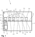
- Figure 1 shows a simplified schematic side view of an autosampler 1 according to the invention for obtaining mass spectra from a plurality of fluid samples. More precisely, in the present embodiment, the autosampler 1 is for obtaining mass spectra from a plurality of gaseous samples.
- the autosampler 1 comprises a plurality of containers 2.1, ..., 2.6 comprising sample sources 3.1, ..., 3.6 providing the samples. These containers 2.1, ..., 2.6 are constructed identically and are thus identical. Each one of the containers 2.1, ..., 2.6 provides an inside with a volume of 2 l. In a variant, each one of the containers 2.1, ..., 2.6 provides an inside with a volume different from 2 l. For example, the volume is 0.1 l. In another example, the volume is 0.5 l. In yet another example, the volume is 1 l, 3 l, 5 l or 10 l. Even a volume smaller than 0.1 l or a volume larger than 10 l is possible, too.
- FIG 1 only six containers 2.1, ..., 2.6 are shown. This is however due to the simplified schematic view shown in Figure 1 .
- the autosampler 1 in fact comprises 120 such containers. Nonetheless, this number is not fixed.
- the autosampler may comprise less containers like for example 100 containers, 50 containers, 10 containers or even exactly 6 containers as shown in Figure 1 or only 5 containers. Even a larger number of containers like 200 containers or 500 containers or even more containers is possible, too.
- the sample sources 3.1, ..., 3.6 can be plants, microorganisms or objects or liquids.
- the sample sources 3.1, ..., 3.6 can be wood, fabric, plastic elements or anything which degases some gas which is to be analysed with the autosampler 1.
- each one of the containers 2.1, ..., 2.6 comprises a heating unit 18.1, 18.2.
- the heating units 18.1, 18.2 With these heating units 18.1, 18.2, the inside of the containers 2.1, ..., 2.6 and thus the sample sources 3.1, ..., 3.6 can be heated.
- the autosampler 1 may comprise one heating unit for heating the containers 2.1, ..., 2.6 with their contents.
- the autosampler 1 goes without such one or more heating units 18.1, 18.2.
- Each one of the containers 2.1, ..., 2.6 provides a docking port 4.1, ..., 4.6 for being connected with a connector 5 for enabling access to an inside of the respective container 2.1, ..., 2.6 via the connector 5 when the connector 5 is connected to the respective docking port 4.1, ..., 4.6 in order to obtain the respective sample from the respective container 2.1, ..., 2.6 via the connector 5.
- the connector 5 is connectable to and detachable from each docking port 2.1, ..., 2.6.
- the connector 5 is connectable to one of the docking ports 2.1, ..., 2.6 at a time.
- the docking ports 4.1, ..., 4.6 of the containers 2.1, ..., 2.6 are constructed identically and are thus identical.
- the autosampler 1 further comprises an ionisation source 6 for ionising at least a part of the samples to ions.
- This ionisation source 6 is in the present case a proton transfer reaction (PTR) ionisation source.
- PTR proton transfer reaction
- the ionisation source 6 can however be any other ionisation source, too.
- the ionisation source 6 can be a chemical reaction ionisation source, a plasma ionisation source or even an electrospray ionisation source.
- the ionisation source 6 is fluidly coupled to the connector 5 for receiving the samples from the containers 2.1, ..., 2.6 via the connector 5.
- the autosampler 1 comprises a mass analyser 7 for obtaining mass spectra from the ions.
- This mass analyser 7 is in the present case a time-of-flight mass analyser.
- the mass analyser 7 can be any other type of mass analyser like for example a quadrupole mass analyser.
- the mass analyser 7 is fluidly coupled to the ionisation source 6 for receiving the ions from the ionisation source 6 for obtaining the mass spectra from the ions.
- the autosampler 1 may comprise an ion mobility spectrometer, too.
- This ion mobility spectrometer comprises a drifting region for separating the ions passing the drifting region according to their mobility.
- the ion mobility spectrometer comprises a detector for detecting the ions having passed the drifting region.
- this detector is the mass analyser.
- the ions from the ionisation source are inserted in a pulsed manner into the drifting region.
- the ionisation source may provide the ions in a pulsed manner or there may be an ion gate between the ionisation source and the drifting region which inserts the ions in a pulsed manner into the drifting region.
- the mass analyser receives the ions having passed the drifting region and detects the time when the ions have arrived at the mass analyser for determining ion mobility spectra of the ions.
- the autosampler 1 goes without ion mobility spectrometer.
- the ionisation source 6 is moveable together with the connector 5 and the mass analyser 7 within the autosampler 1 sequentially to each one of the plurality of said containers 2.1, .., 2.6 for connecting the connector 5 to the docking port 4.1, ..., 4.6 of the respective container 2.1, ..., 2.6 for collecting the sample from the respective container 2.1, ..., 2.6 for ionising at least a part of the sample to ions and for obtaining the mass spectra from the ions.
- the autosampler 1 furthermore comprises a frame 11. On this frame 11, a support surface 14 is mounted. On this support surface 14, the containers 2.1, ..., 2.6 are mounted. Below the support surface 14, the ionisation source 6 is moveable with the connector 5 within the autosampler 1 sequentially to each one of the plurality of the containers 2.1, ..., 2.6 for connecting the connector 5 to the docking port 4.1, ..., 4.6 of the respective container 2.1, ..., 2.6 for collecting the sample from the respective container 2.1, ..., 2.6 for ionising at least a part of the sample to ions and for obtaining the mass spectra from the ions.
- the support surface 14 provides openings reaching from an upper side of the support surface 14 to a lower side of the support surface 14, wherein for each docking port 4.1, ..., 4.6, a connecting area of the respective docking port 4.1, ..., 4.6 for being connected with the connector 5 is located on said lower side of the support surface 14.
- the ionisation source 6 and the mass analyser 7 are mounted together in a housing 12.
- This housing 12 provides wheels and a driving unit 8 in the form of an electric motor for moving the housing 12 with the ionisation source 6 and the mass analyser 7 below the surface 14.
- the driving unit 8 is a pneumatic system.
- the housing 12 is moveable along a straight line which is a linear path.
- the ionisation source 6 is moveable within the autosampler 1 along an overlapping-free linear path for being moved sequentially to each one of the plurality of the containers 2.1, ..., 2.6 for connecting the connector 5 to the docking port 4.1, ..., 4.6 of the respective container 2.1, ..., 2.6 for collecting the sample from the respective container 2.1, ..., 2.6 for ionising at least a part of the sample to ions and for obtaining the mass spectra from the ions.
- the housing 12 is moveable in two dimensions in a plane parallel to the support surface 14.
- ionisation source 6 is moveable within the autosampler 1 in only two dimensions for being moved sequentially to each one of the plurality of the containers 2.1, ..., 2.6 for connecting the connector 5 to the docking port 4.1, ..., 4.6 of the respective container 2.1, ..., 2.6 for collecting the sample from the respective container 2.1, ..., 2.6 for ionising at least a part of the sample to ions and for obtaining the mass spectra from the ions.
- the connector 5 reaches from the housing 12 upwards and can be moved upwards and downwards by some driving unit 19 in order to connect the connector 5 to one of the docking ports 4.1, ..., 4.6 and in order to detach the connector 5 again from the respective docking port 4.1, ..., 4.6.
- This driving unit 19 for connecting the connector 5 to one of the docking ports 4.1, ..., 4.6 and for detaching the connector 5 again from the respective docking port 4.1, ..., 4.6 can comprise an electric motor, a pneumatic system or the like for actuating the movement of the connector 5.
- the connector 5 is fixed to the housing 12.
- the entire housing can be lifted and lowered such that the connector 5 can be moved upwards and downwards together with the housing by some driving unit in order to connect the connector 5 to one of the docking ports 4.1, ..., 4.6 and in order to detach the connector 5 again from the respective docking port 4.1, ..., 4.6.
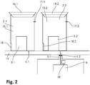
- Figure 2 shows a detail view of Figure 1 . Nonetheless, Figure 2 still shows a simplified schematic view. It shows two of the containers 2.1, 2.2 mounted on the support surface 14 and an upper part of the housing 12 with the ionisation source 6 and the connector 5 being connected to the docking port 4.2 of one of the two containers 2.2.
- the docking ports 4.1, 4.2 are each simply the end of a tube.
- the end of the tube may somewhat overshoot the lower side of the support surface 14 as illustrated in Figure 2 .
- the end of the tube may as well by flush with the lower side of the support surface.
- the containers 2.1, 2.2 are jars 15.1, 15.2 having a lid 16.1, 16.2. When covered with the lids, 16.1, 16.2, the containers 2.1, 2.2 are air tight sealed. These jars are 15.1, 15.2 made from glass. Instead of glass, they may however as well be made of Teflon, stainless steel or any other suitable material.
- a small tube reaches through one of the openings in the support surface 14 form the upper side of the support surface 14 to the lower side of the support surface 14.
- the docking ports 4.1, 4.2 are arranged.
- a gas inlet 17.1, 17.2 for inserting a purge gas into the respective jar 15.1, 15.2 is provided in the side wall of each jar 15.1, 15.2, a gas inlet 17.1, 17.2 for inserting a purge gas into the respective jar 15.1, 15.2 is provided.
- these gas inlets 17.1, 17.2 are each connected to a purge gas source 13.
- This purge gas source 13 comprises a purge gas.
- this purge gas is nitrogen.
- the purge gas can be any other gas, too.
- it can be an inert gas.
- the purge gas source 13 contains the purge gas under pressure.
- the samples provided by the sample sources 3.1, ..., 3.6 are purged out of the containers 2.1, ..., 2.6. Consequently, when the connector 5 is connected to one of the docking ports 4.1, .., 4.6, the sample is purged from the respective container 2.1, ..., 2.6 via the connector 5 to the ionisation source 6.
- the autosampler 1 comprises a vacuum pump 9.
- This vacuum pump 9 is located in the housing 12 and produces a lower pressure in the ionisation source 6 as compared to a pressure in the containers 2.1, ..., 2.6.
- the autosampler 1 comprises a control unit 10 for controlling the autosampler 1.
- This control unit 10 controls the flow of the purge gas from the purge gas source 13 to the containers 2.1, ..., 2.6, the heating units 18.1, 18.2 of the containers, 2.1, ..., 2.6, the movement of the housing 12 with the ionisation source 6, the mass analyser 7 and the connector 5.
- the control unit 10 controls the movement of the connector 5 when connecting to one of the docking ports 4.1, ..., 4.6 as well as when detaching from the connector 5 from one of the docking ports 4.1, ..., .4.6.
- the control unit 10 controls the ionisation source 6 and the mass analyser 7.
- the control unit 10 can be of any type.
- the control unit 10 is a computer. This computer may be mounted inside the frame 11 or may be located outside of the frame 11.
- the control unit 10 is further adapted for repetitively sample the plurality of samples.
- the temporal evolution of the sample sources can be observed because mass spectra are repeatedly obtained from samples originating from the same sample sources.
- the sample sources 3.1, 3.2, 3.3, 3.4, 3.5, 3.6 providing the samples are kept in the containers 2.1, 2.2, 2.3, 2.4, 2.5, 2.6 and the containers 2.1, 2.2, 2.3, 2.4, 2.5, 2.6 are sequentially sampled.
- the housing 12 with ionisation source 6, the mass analyser 7 and the connector 5 are moved within the autosampler 1 sequentially to each one of the plurality of said containers 2.1, 2.2, 2.3, 2.4, 2.5, 2.6, the connector 5 is each time connected to the docking port 4.1, 4.2, 4.3, 4.4, 4.5, 4.6 of the respective container 2.1, 2.2, 2.3, 2.4, 2.5, 2.6, the respective sample is collected from the respective container 2.1, 2.2, 2.3, 2.4, 2.5, 2.6 and transferred via the connector 5 to the ionisation source 6, where at least a part of the respective sample is ionised to ions. Subsequently, the ions are transferred to the mass analyser 7 where the mass spectra are obtained from the ions.
- the connector 5 is detached from the docking port 4.1, 4.2, 4.3, 4.4, 4.5, 4.6 of the respective container 2.1, 2.2, 2.3, 2.4, 2.5, 2.6.
- this time may however be different from 5 s. For example, it may be only 1 s, but it may as well be 30 s, 60 s or even minutes like 30 minutes or more.
- the connector 5 is detached from the docking port 4.1, 4.2, 4.3, 4.4, 4.5, 4.6 of one of the containers 2.1, 2.2, 2.3, 2.4, 2.5, 2.6, the housing 12 with the ionisation source 6, the mass analyser 7 and the connector 5 are moved within the autosampler 1 to the next one of the containers 2.1, 2.2, 2.3, 2.4, 2.5, 2.6 and the connector 5 is connected to this next one of the containers 2.1, 2.2, 2.3, 2.4, 2.5, 2.6 until all containers 2.1, 2.2, 2.3, 2.4, 2.5, 2.6 have been sampled.
- Each such change from one container 2.1, 2.2, 2.3, 2.4, 2.5, 2.6 to the next container 2.1, 2.2, 2.3, 2.4, 2.5, 2.6 takes a time from 1 s to 30 seconds. Alternatively however, this may take a shorter or a longer time.
- mass spectra are obtained repeatedly. Even more, mass spectra are obtained repeatedly as well when none of the containers 2.1, 2.2, 2.3, 2.4, 2.5, 2.6 is sampled. This has the advantage that any leftovers in the system from samples originating from containers 2.1, 2.2, 2.3, 2.4, 2.5, 2.6 previously sampled can be identified which lead to contaminations in mass spectra obtained from containers 2.1, 2.2, 2.3, 2.4, 2.5, 2.6 which are later sampled. In a variant however, mass spectra can be obtained repeatedly only when one of the containers 2.1, 2.2, 2.3, 2.4, 2.5, 2.6 is sampled.
- the autosampler is not required to obtain mass spectra from a plurality of gaseous samples.
- the autosampler can be adapted for obtaining mass spectra from a plurality of liquid samples.
- the ionisation source is preferably an electrospray ionisation source.
- an autosampler and a method for operating such an autosampler that enable obtaining more accurate mass spectra of a plurality of fluid samples are provided.
Landscapes
- Chemical & Material Sciences (AREA)
- Analytical Chemistry (AREA)
- Other Investigation Or Analysis Of Materials By Electrical Means (AREA)
Priority Applications (5)
| Application Number | Priority Date | Filing Date | Title |
|---|---|---|---|
| EP18155008.8A EP3522201B1 (de) | 2018-02-02 | 2018-02-02 | Autosampler |
| TW108104222A TW201937147A (zh) | 2018-02-02 | 2019-02-01 | 自動取樣器 |
| US16/962,904 US11227755B2 (en) | 2018-02-02 | 2019-02-01 | Autosampler |
| CN201980010971.5A CN111670485B (zh) | 2018-02-02 | 2019-02-01 | 自动取样器 |
| PCT/EP2019/052533 WO2019149903A1 (en) | 2018-02-02 | 2019-02-01 | Autosampler |
Applications Claiming Priority (1)
| Application Number | Priority Date | Filing Date | Title |
|---|---|---|---|
| EP18155008.8A EP3522201B1 (de) | 2018-02-02 | 2018-02-02 | Autosampler |
Publications (2)
| Publication Number | Publication Date |
|---|---|
| EP3522201A1 true EP3522201A1 (de) | 2019-08-07 |
| EP3522201B1 EP3522201B1 (de) | 2020-10-07 |
Family
ID=61157140
Family Applications (1)
| Application Number | Title | Priority Date | Filing Date |
|---|---|---|---|
| EP18155008.8A Active EP3522201B1 (de) | 2018-02-02 | 2018-02-02 | Autosampler |
Country Status (5)
| Country | Link |
|---|---|
| US (1) | US11227755B2 (de) |
| EP (1) | EP3522201B1 (de) |
| CN (1) | CN111670485B (de) |
| TW (1) | TW201937147A (de) |
| WO (1) | WO2019149903A1 (de) |
Families Citing this family (1)
| Publication number | Priority date | Publication date | Assignee | Title |
|---|---|---|---|---|
| EP4445407A2 (de) * | 2021-12-07 | 2024-10-16 | Deutsches Krebsforschungszentrum | Automatisiertes system zur bereitstellung mindestens einer probe zur elektrosprayionisierung in einem massenspektrometersystem |
Citations (5)
| Publication number | Priority date | Publication date | Assignee | Title |
|---|---|---|---|---|
| WO2000062039A1 (en) * | 1999-04-09 | 2000-10-19 | Northeastern University | System and method for high throughput mass spectrometric analysis |
| US20120153143A1 (en) * | 2009-06-19 | 2012-06-21 | The Regents Of The University Of Michigan | Electrospray and nanospray ionization of discrete samples in droplet format |
| EP2572188A1 (de) * | 2010-05-21 | 2013-03-27 | Antec Leyden B.V. | Analysator mit einer elektrochemischen durchflusszelle und strukturaufklärungsspektrometer |
| WO2013076496A1 (en) * | 2011-11-22 | 2013-05-30 | Micromass Uk Limited | Low cross-talk fast sample delivery system based upon acoustic droplet ejection |
| US20140283627A1 (en) * | 2013-03-25 | 2014-09-25 | Thermo Electron Manufacturing Limited | Apparatus and method for liquid sample introduction |
Family Cites Families (28)
| Publication number | Priority date | Publication date | Assignee | Title |
|---|---|---|---|---|
| US6458597B1 (en) * | 1999-03-22 | 2002-10-01 | Analytica Of Branford, Inc. | Direct flow injection analysis nebulization electrospray and apci mass spectrometry |
| US6872362B2 (en) * | 2000-03-10 | 2005-03-29 | Teledyne Tekmar Company | Vial handling system with improved mixing mechanism |
| US6864480B2 (en) * | 2001-12-19 | 2005-03-08 | Sau Lan Tang Staats | Interface members and holders for microfluidic array devices |
| US6825466B2 (en) * | 2002-08-01 | 2004-11-30 | Automated Biotechnology, Inc. | Apparatus and method for automated sample analysis by atmospheric pressure matrix assisted laser desorption ionization mass spectrometry |
| US7214320B1 (en) * | 2002-08-08 | 2007-05-08 | Nanostream, Inc. | Systems and methods for high throughput sample analysis |
| US8174276B2 (en) * | 2008-05-22 | 2012-05-08 | Texas Instruments Incorporated | Coaxial four-point probe for low resistance measurements |
| EP2396803A4 (de) * | 2009-02-12 | 2016-10-26 | Ibis Biosciences Inc | Ionisationssondenanordnungen |
| US20100224013A1 (en) * | 2009-03-05 | 2010-09-09 | Van Berkel Gary J | Method and system for formation and withdrawal of a sample from a surface to be analyzed |
| US8704167B2 (en) * | 2009-04-30 | 2014-04-22 | Purdue Research Foundation | Mass spectrometry analysis of microorganisms in samples |
| US8546752B2 (en) * | 2009-12-07 | 2013-10-01 | Advion Inc. | Solid-phase extraction (SPE) tips and methods of use |
| US8258469B2 (en) * | 2010-03-15 | 2012-09-04 | National Sun Yat-Sen University | Cycling electrospray ionization device |
| US20110287550A1 (en) * | 2010-05-24 | 2011-11-24 | National Sun Yat-Sen University | Method for continuously monitoring solution-phase synthesis of oligonucleotide |
| DE102010022017A1 (de) * | 2010-05-29 | 2011-12-01 | Gerstel Systemtechnik Gmbh & Co.Kg | Verfahren zur Probenvorbereitung bei chromatographischen Trennmethoden und Vorrichtungen zur Durchführung einer Probenvorbereitung |
| US9153425B2 (en) * | 2010-09-01 | 2015-10-06 | Ut-Battelle, Llc | Device for high spatial resolution chemical analysis of a sample and method of high spatial resolution chemical analysis |
| US8519330B2 (en) * | 2010-10-01 | 2013-08-27 | Ut-Battelle, Llc | Systems and methods for laser assisted sample transfer to solution for chemical analysis |
| AU2011320358B2 (en) * | 2010-10-29 | 2015-09-03 | Thermo Fisher Scientific Oy | Automated system for sample preparation and analysis |
| WO2012167126A1 (en) * | 2011-06-03 | 2012-12-06 | Purdue Research Foundation | Ion generation using modified wetted porous materials |
| US8894946B2 (en) * | 2011-10-21 | 2014-11-25 | Integenx Inc. | Sample preparation, processing and analysis systems |
| JP6346567B2 (ja) * | 2011-12-28 | 2018-06-20 | マイクロマス・ユーケー・リミテッド | 液相試料の急速蒸発イオン化を行うためのシステムおよび方法 |
| JP6035603B2 (ja) * | 2012-12-19 | 2016-11-30 | 株式会社日立ハイテクノロジーズ | 試料導入装置 |
| AU2016219358B2 (en) * | 2015-02-10 | 2018-06-28 | Indiana University Research And Technology Corporation | Device and method for analysis of biofluids by ion generation using wetted porous material |
| CA2978048A1 (en) * | 2015-03-06 | 2016-09-15 | Micromass Uk Limited | Liquid trap or separator for electrosurgical applications |
| CN104966660B (zh) * | 2015-07-27 | 2018-04-24 | 北京凯尔科技发展有限公司 | 一种质子转移质谱仪及其使用方法 |
| EP4357784A3 (de) * | 2016-09-02 | 2024-07-31 | Board of Regents, The University of Texas System | Erfassungssonde und verfahren zur verwendung davon |
| CN106960777B (zh) * | 2016-12-31 | 2019-08-20 | 宁波华仪宁创智能科技有限公司 | 质谱分析系统及其工作方法 |
| CN206441693U (zh) * | 2016-12-31 | 2017-08-25 | 宁波华仪宁创智能科技有限公司 | 质谱分析系统 |
| US11219393B2 (en) * | 2018-07-12 | 2022-01-11 | Trace Matters Scientific Llc | Mass spectrometry system and method for analyzing biological samples |
| US11139157B2 (en) * | 2019-05-31 | 2021-10-05 | Purdue Research Foundation | Multiplexed inductive ionization systems and methods |
-
2018
- 2018-02-02 EP EP18155008.8A patent/EP3522201B1/de active Active
-
2019
- 2019-02-01 WO PCT/EP2019/052533 patent/WO2019149903A1/en not_active Ceased
- 2019-02-01 US US16/962,904 patent/US11227755B2/en active Active
- 2019-02-01 CN CN201980010971.5A patent/CN111670485B/zh active Active
- 2019-02-01 TW TW108104222A patent/TW201937147A/zh unknown
Patent Citations (5)
| Publication number | Priority date | Publication date | Assignee | Title |
|---|---|---|---|---|
| WO2000062039A1 (en) * | 1999-04-09 | 2000-10-19 | Northeastern University | System and method for high throughput mass spectrometric analysis |
| US20120153143A1 (en) * | 2009-06-19 | 2012-06-21 | The Regents Of The University Of Michigan | Electrospray and nanospray ionization of discrete samples in droplet format |
| EP2572188A1 (de) * | 2010-05-21 | 2013-03-27 | Antec Leyden B.V. | Analysator mit einer elektrochemischen durchflusszelle und strukturaufklärungsspektrometer |
| WO2013076496A1 (en) * | 2011-11-22 | 2013-05-30 | Micromass Uk Limited | Low cross-talk fast sample delivery system based upon acoustic droplet ejection |
| US20140283627A1 (en) * | 2013-03-25 | 2014-09-25 | Thermo Electron Manufacturing Limited | Apparatus and method for liquid sample introduction |
Also Published As
| Publication number | Publication date |
|---|---|
| WO2019149903A1 (en) | 2019-08-08 |
| CN111670485A (zh) | 2020-09-15 |
| US20210066058A1 (en) | 2021-03-04 |
| TW201937147A (zh) | 2019-09-16 |
| CN111670485B (zh) | 2024-09-17 |
| EP3522201B1 (de) | 2020-10-07 |
| US11227755B2 (en) | 2022-01-18 |
Similar Documents
| Publication | Publication Date | Title |
|---|---|---|
| US11619643B2 (en) | Arrangement for preparing a plurality of samples for an analytical method | |
| US10801930B2 (en) | Method for preparing a sample for chromatographic separation processes and system for carrying out a sample preparation | |
| US5866072A (en) | Analytical pyrolysis autosampler | |
| EP2632566B1 (de) | Analyse von molekularer kontamination in vakuumumgebungen | |
| EP1054256B1 (de) | Adapter zur Desorption von Probenröhrchen, Anordnug bestehend aus Gaschromatograph und Adapter, sowie Bausatz zur Bildung einer solchen Anordnung | |
| EP4094082B1 (de) | Autosampler | |
| CN114072679A (zh) | 自动分析装置 | |
| US11227755B2 (en) | Autosampler | |
| EP2520922B1 (de) | Probeneinführungsvorrichtung für ein spurenerkennungsmessgerät und spurenerkennungsmessgerät mit der probeneinführungsvorrichtung | |
| US20040002166A1 (en) | Remote analysis using aerosol sample transport | |
| US11581177B2 (en) | System for introducing particle-containing samples to an analytical instrument and methods of use | |
| US6743397B1 (en) | Device for qualifying products containing volatile substances | |
| US9061281B2 (en) | System for carrying out a sample preparation | |
| JP2010066243A (ja) | 物質検査装置および物質検査方法 | |
| US6257757B1 (en) | Thermal analysis apparatus | |
| JP4653286B2 (ja) | サンプリングバイアルを脱着するための組立体、前記組立体用に明白に意図されたアダプタとサンプリングバイアル、および、前記組立体を形成するための部品キット | |
| US20240168046A1 (en) | Systems and methods for humidity and/or temperature control in a sample analysis system | |
| CN112951700B (zh) | 一种单路双标定的质谱进样装置和方法 | |
| CN115372530A (zh) | 利用气体注射的自动吹扫系统 | |
| SU1398581A1 (ru) | Устройство дл подготовки проб к аналитическому определению элементов в газовой фазе | |
| JP4017092B2 (ja) | 発生ガス分析装置およびガス導入インターフェース | |
| US20210175062A1 (en) | Sample preparation for maldi-tof | |
| WO2025204616A1 (ja) | 処理装置 | |
| CN121975610A (zh) | 一种全自动核酸扩增设备 | |
| KR20240055768A (ko) | 분석 시스템용 오븐, 적정 시스템 및 적정 방법 |
Legal Events
| Date | Code | Title | Description |
|---|---|---|---|
| PUAI | Public reference made under article 153(3) epc to a published international application that has entered the european phase |
Free format text: ORIGINAL CODE: 0009012 |
|
| STAA | Information on the status of an ep patent application or granted ep patent |
Free format text: STATUS: THE APPLICATION HAS BEEN PUBLISHED |
|
| AK | Designated contracting states |
Kind code of ref document: A1 Designated state(s): AL AT BE BG CH CY CZ DE DK EE ES FI FR GB GR HR HU IE IS IT LI LT LU LV MC MK MT NL NO PL PT RO RS SE SI SK SM TR |
|
| AX | Request for extension of the european patent |
Extension state: BA ME |
|
| STAA | Information on the status of an ep patent application or granted ep patent |
Free format text: STATUS: REQUEST FOR EXAMINATION WAS MADE |
|
| 17P | Request for examination filed |
Effective date: 20191105 |
|
| RBV | Designated contracting states (corrected) |
Designated state(s): AL AT BE BG CH CY CZ DE DK EE ES FI FR GB GR HR HU IE IS IT LI LT LU LV MC MK MT NL NO PL PT RO RS SE SI SK SM TR |
|
| GRAP | Despatch of communication of intention to grant a patent |
Free format text: ORIGINAL CODE: EPIDOSNIGR1 |
|
| STAA | Information on the status of an ep patent application or granted ep patent |
Free format text: STATUS: GRANT OF PATENT IS INTENDED |
|
| INTG | Intention to grant announced |
Effective date: 20200103 |
|
| GRAJ | Information related to disapproval of communication of intention to grant by the applicant or resumption of examination proceedings by the epo deleted |
Free format text: ORIGINAL CODE: EPIDOSDIGR1 |
|
| STAA | Information on the status of an ep patent application or granted ep patent |
Free format text: STATUS: REQUEST FOR EXAMINATION WAS MADE |
|
| GRAP | Despatch of communication of intention to grant a patent |
Free format text: ORIGINAL CODE: EPIDOSNIGR1 |
|
| STAA | Information on the status of an ep patent application or granted ep patent |
Free format text: STATUS: GRANT OF PATENT IS INTENDED |
|
| INTG | Intention to grant announced |
Effective date: 20200504 |
|
| GRAJ | Information related to disapproval of communication of intention to grant by the applicant or resumption of examination proceedings by the epo deleted |
Free format text: ORIGINAL CODE: EPIDOSDIGR1 |
|
| STAA | Information on the status of an ep patent application or granted ep patent |
Free format text: STATUS: REQUEST FOR EXAMINATION WAS MADE |
|
| GRAP | Despatch of communication of intention to grant a patent |
Free format text: ORIGINAL CODE: EPIDOSNIGR1 |
|
| STAA | Information on the status of an ep patent application or granted ep patent |
Free format text: STATUS: GRANT OF PATENT IS INTENDED |
|
| INTC | Intention to grant announced (deleted) | ||
| INTG | Intention to grant announced |
Effective date: 20200626 |
|
| GRAS | Grant fee paid |
Free format text: ORIGINAL CODE: EPIDOSNIGR3 |
|
| GRAA | (expected) grant |
Free format text: ORIGINAL CODE: 0009210 |
|
| STAA | Information on the status of an ep patent application or granted ep patent |
Free format text: STATUS: THE PATENT HAS BEEN GRANTED |
|
| RAP1 | Party data changed (applicant data changed or rights of an application transferred) |
Owner name: TOFWERK AG |
|
| AK | Designated contracting states |
Kind code of ref document: B1 Designated state(s): AL AT BE BG CH CY CZ DE DK EE ES FI FR GB GR HR HU IE IS IT LI LT LU LV MC MK MT NL NO PL PT RO RS SE SI SK SM TR |
|
| REG | Reference to a national code |
Ref country code: GB Ref legal event code: FG4D |
|
| REG | Reference to a national code |
Ref country code: AT Ref legal event code: REF Ref document number: 1322045 Country of ref document: AT Kind code of ref document: T Effective date: 20201015 Ref country code: CH Ref legal event code: EP |
|
| REG | Reference to a national code |
Ref country code: IE Ref legal event code: FG4D |
|
| REG | Reference to a national code |
Ref country code: DE Ref legal event code: R096 Ref document number: 602018008361 Country of ref document: DE |
|
| REG | Reference to a national code |
Ref country code: CH Ref legal event code: NV Representative=s name: KELLER SCHNEIDER PATENT- UND MARKENANWAELTE AG, CH |
|
| REG | Reference to a national code |
Ref country code: NL Ref legal event code: MP Effective date: 20201007 |
|
| PG25 | Lapsed in a contracting state [announced via postgrant information from national office to epo] |
Ref country code: FI Free format text: LAPSE BECAUSE OF FAILURE TO SUBMIT A TRANSLATION OF THE DESCRIPTION OR TO PAY THE FEE WITHIN THE PRESCRIBED TIME-LIMIT Effective date: 20201007 Ref country code: RS Free format text: LAPSE BECAUSE OF FAILURE TO SUBMIT A TRANSLATION OF THE DESCRIPTION OR TO PAY THE FEE WITHIN THE PRESCRIBED TIME-LIMIT Effective date: 20201007 Ref country code: PT Free format text: LAPSE BECAUSE OF FAILURE TO SUBMIT A TRANSLATION OF THE DESCRIPTION OR TO PAY THE FEE WITHIN THE PRESCRIBED TIME-LIMIT Effective date: 20210208 Ref country code: GR Free format text: LAPSE BECAUSE OF FAILURE TO SUBMIT A TRANSLATION OF THE DESCRIPTION OR TO PAY THE FEE WITHIN THE PRESCRIBED TIME-LIMIT Effective date: 20210108 Ref country code: NO Free format text: LAPSE BECAUSE OF FAILURE TO SUBMIT A TRANSLATION OF THE DESCRIPTION OR TO PAY THE FEE WITHIN THE PRESCRIBED TIME-LIMIT Effective date: 20210107 |
|
| REG | Reference to a national code |
Ref country code: LT Ref legal event code: MG4D |
|
| PG25 | Lapsed in a contracting state [announced via postgrant information from national office to epo] |
Ref country code: ES Free format text: LAPSE BECAUSE OF FAILURE TO SUBMIT A TRANSLATION OF THE DESCRIPTION OR TO PAY THE FEE WITHIN THE PRESCRIBED TIME-LIMIT Effective date: 20201007 Ref country code: BG Free format text: LAPSE BECAUSE OF FAILURE TO SUBMIT A TRANSLATION OF THE DESCRIPTION OR TO PAY THE FEE WITHIN THE PRESCRIBED TIME-LIMIT Effective date: 20210107 Ref country code: LV Free format text: LAPSE BECAUSE OF FAILURE TO SUBMIT A TRANSLATION OF THE DESCRIPTION OR TO PAY THE FEE WITHIN THE PRESCRIBED TIME-LIMIT Effective date: 20201007 Ref country code: PL Free format text: LAPSE BECAUSE OF FAILURE TO SUBMIT A TRANSLATION OF THE DESCRIPTION OR TO PAY THE FEE WITHIN THE PRESCRIBED TIME-LIMIT Effective date: 20201007 Ref country code: IS Free format text: LAPSE BECAUSE OF FAILURE TO SUBMIT A TRANSLATION OF THE DESCRIPTION OR TO PAY THE FEE WITHIN THE PRESCRIBED TIME-LIMIT Effective date: 20210207 Ref country code: SE Free format text: LAPSE BECAUSE OF FAILURE TO SUBMIT A TRANSLATION OF THE DESCRIPTION OR TO PAY THE FEE WITHIN THE PRESCRIBED TIME-LIMIT Effective date: 20201007 |
|
| PG25 | Lapsed in a contracting state [announced via postgrant information from national office to epo] |
Ref country code: NL Free format text: LAPSE BECAUSE OF FAILURE TO SUBMIT A TRANSLATION OF THE DESCRIPTION OR TO PAY THE FEE WITHIN THE PRESCRIBED TIME-LIMIT Effective date: 20201007 Ref country code: HR Free format text: LAPSE BECAUSE OF FAILURE TO SUBMIT A TRANSLATION OF THE DESCRIPTION OR TO PAY THE FEE WITHIN THE PRESCRIBED TIME-LIMIT Effective date: 20201007 |
|
| REG | Reference to a national code |
Ref country code: DE Ref legal event code: R097 Ref document number: 602018008361 Country of ref document: DE |
|
| PG25 | Lapsed in a contracting state [announced via postgrant information from national office to epo] |
Ref country code: EE Free format text: LAPSE BECAUSE OF FAILURE TO SUBMIT A TRANSLATION OF THE DESCRIPTION OR TO PAY THE FEE WITHIN THE PRESCRIBED TIME-LIMIT Effective date: 20201007 Ref country code: CZ Free format text: LAPSE BECAUSE OF FAILURE TO SUBMIT A TRANSLATION OF THE DESCRIPTION OR TO PAY THE FEE WITHIN THE PRESCRIBED TIME-LIMIT Effective date: 20201007 Ref country code: LT Free format text: LAPSE BECAUSE OF FAILURE TO SUBMIT A TRANSLATION OF THE DESCRIPTION OR TO PAY THE FEE WITHIN THE PRESCRIBED TIME-LIMIT Effective date: 20201007 Ref country code: SM Free format text: LAPSE BECAUSE OF FAILURE TO SUBMIT A TRANSLATION OF THE DESCRIPTION OR TO PAY THE FEE WITHIN THE PRESCRIBED TIME-LIMIT Effective date: 20201007 Ref country code: SK Free format text: LAPSE BECAUSE OF FAILURE TO SUBMIT A TRANSLATION OF THE DESCRIPTION OR TO PAY THE FEE WITHIN THE PRESCRIBED TIME-LIMIT Effective date: 20201007 Ref country code: RO Free format text: LAPSE BECAUSE OF FAILURE TO SUBMIT A TRANSLATION OF THE DESCRIPTION OR TO PAY THE FEE WITHIN THE PRESCRIBED TIME-LIMIT Effective date: 20201007 |
|
| PLBE | No opposition filed within time limit |
Free format text: ORIGINAL CODE: 0009261 |
|
| STAA | Information on the status of an ep patent application or granted ep patent |
Free format text: STATUS: NO OPPOSITION FILED WITHIN TIME LIMIT |
|
| PG25 | Lapsed in a contracting state [announced via postgrant information from national office to epo] |
Ref country code: DK Free format text: LAPSE BECAUSE OF FAILURE TO SUBMIT A TRANSLATION OF THE DESCRIPTION OR TO PAY THE FEE WITHIN THE PRESCRIBED TIME-LIMIT Effective date: 20201007 |
|
| 26N | No opposition filed |
Effective date: 20210708 |
|
| PG25 | Lapsed in a contracting state [announced via postgrant information from national office to epo] |
Ref country code: MC Free format text: LAPSE BECAUSE OF FAILURE TO SUBMIT A TRANSLATION OF THE DESCRIPTION OR TO PAY THE FEE WITHIN THE PRESCRIBED TIME-LIMIT Effective date: 20201007 |
|
| REG | Reference to a national code |
Ref country code: BE Ref legal event code: MM Effective date: 20210228 |
|
| PG25 | Lapsed in a contracting state [announced via postgrant information from national office to epo] |
Ref country code: IT Free format text: LAPSE BECAUSE OF FAILURE TO SUBMIT A TRANSLATION OF THE DESCRIPTION OR TO PAY THE FEE WITHIN THE PRESCRIBED TIME-LIMIT Effective date: 20201007 Ref country code: LU Free format text: LAPSE BECAUSE OF NON-PAYMENT OF DUE FEES Effective date: 20210202 Ref country code: AL Free format text: LAPSE BECAUSE OF FAILURE TO SUBMIT A TRANSLATION OF THE DESCRIPTION OR TO PAY THE FEE WITHIN THE PRESCRIBED TIME-LIMIT Effective date: 20201007 |
|
| PG25 | Lapsed in a contracting state [announced via postgrant information from national office to epo] |
Ref country code: SI Free format text: LAPSE BECAUSE OF FAILURE TO SUBMIT A TRANSLATION OF THE DESCRIPTION OR TO PAY THE FEE WITHIN THE PRESCRIBED TIME-LIMIT Effective date: 20201007 |
|
| PG25 | Lapsed in a contracting state [announced via postgrant information from national office to epo] |
Ref country code: FR Free format text: LAPSE BECAUSE OF NON-PAYMENT OF DUE FEES Effective date: 20210228 Ref country code: IE Free format text: LAPSE BECAUSE OF NON-PAYMENT OF DUE FEES Effective date: 20210202 |
|
| PG25 | Lapsed in a contracting state [announced via postgrant information from national office to epo] |
Ref country code: IS Free format text: LAPSE BECAUSE OF FAILURE TO SUBMIT A TRANSLATION OF THE DESCRIPTION OR TO PAY THE FEE WITHIN THE PRESCRIBED TIME-LIMIT Effective date: 20210207 |
|
| PG25 | Lapsed in a contracting state [announced via postgrant information from national office to epo] |
Ref country code: BE Free format text: LAPSE BECAUSE OF NON-PAYMENT OF DUE FEES Effective date: 20210228 |
|
| PG25 | Lapsed in a contracting state [announced via postgrant information from national office to epo] |
Ref country code: CY Free format text: LAPSE BECAUSE OF FAILURE TO SUBMIT A TRANSLATION OF THE DESCRIPTION OR TO PAY THE FEE WITHIN THE PRESCRIBED TIME-LIMIT Effective date: 20201007 |
|
| PG25 | Lapsed in a contracting state [announced via postgrant information from national office to epo] |
Ref country code: HU Free format text: LAPSE BECAUSE OF FAILURE TO SUBMIT A TRANSLATION OF THE DESCRIPTION OR TO PAY THE FEE WITHIN THE PRESCRIBED TIME-LIMIT; INVALID AB INITIO Effective date: 20180202 |
|
| PG25 | Lapsed in a contracting state [announced via postgrant information from national office to epo] |
Ref country code: MK Free format text: LAPSE BECAUSE OF FAILURE TO SUBMIT A TRANSLATION OF THE DESCRIPTION OR TO PAY THE FEE WITHIN THE PRESCRIBED TIME-LIMIT Effective date: 20201007 |
|
| PGFP | Annual fee paid to national office [announced via postgrant information from national office to epo] |
Ref country code: DE Payment date: 20240116 Year of fee payment: 7 Ref country code: GB Payment date: 20240219 Year of fee payment: 7 |
|
| REG | Reference to a national code |
Ref country code: AT Ref legal event code: UEP Ref document number: 1322045 Country of ref document: AT Kind code of ref document: T Effective date: 20201007 |
|
| PG25 | Lapsed in a contracting state [announced via postgrant information from national office to epo] |
Ref country code: TR Free format text: LAPSE BECAUSE OF FAILURE TO SUBMIT A TRANSLATION OF THE DESCRIPTION OR TO PAY THE FEE WITHIN THE PRESCRIBED TIME-LIMIT Effective date: 20201007 |
|
| PG25 | Lapsed in a contracting state [announced via postgrant information from national office to epo] |
Ref country code: MT Free format text: LAPSE BECAUSE OF FAILURE TO SUBMIT A TRANSLATION OF THE DESCRIPTION OR TO PAY THE FEE WITHIN THE PRESCRIBED TIME-LIMIT Effective date: 20201007 |
|
| REG | Reference to a national code |
Ref country code: DE Ref legal event code: R082 Ref document number: 602018008361 Country of ref document: DE Representative=s name: RAVENSPAT PATENTANWAELTE PARTNERSCHAFT MBB, DE |
|
| REG | Reference to a national code |
Ref country code: DE Ref legal event code: R119 Ref document number: 602018008361 Country of ref document: DE |
|
| GBPC | Gb: european patent ceased through non-payment of renewal fee |
Effective date: 20250202 |
|
| PG25 | Lapsed in a contracting state [announced via postgrant information from national office to epo] |
Ref country code: DE Free format text: LAPSE BECAUSE OF NON-PAYMENT OF DUE FEES Effective date: 20250902 |
|
| PG25 | Lapsed in a contracting state [announced via postgrant information from national office to epo] |
Ref country code: GB Free format text: LAPSE BECAUSE OF NON-PAYMENT OF DUE FEES Effective date: 20250202 |
|
| REG | Reference to a national code |
Ref country code: CH Ref legal event code: U11 Free format text: ST27 STATUS EVENT CODE: U-0-0-U10-U11 (AS PROVIDED BY THE NATIONAL OFFICE) Effective date: 20260301 |
|
| PGFP | Annual fee paid to national office [announced via postgrant information from national office to epo] |
Ref country code: AT Payment date: 20260116 Year of fee payment: 9 |
|
| PGFP | Annual fee paid to national office [announced via postgrant information from national office to epo] |
Ref country code: CH Payment date: 20260301 Year of fee payment: 9 |