EP3522415A1 - Procédé et dispositif pour transmettre des données dans un système de communication cellulaire sans fil - Google Patents
Procédé et dispositif pour transmettre des données dans un système de communication cellulaire sans fil Download PDFInfo
- Publication number
- EP3522415A1 EP3522415A1 EP17867698.7A EP17867698A EP3522415A1 EP 3522415 A1 EP3522415 A1 EP 3522415A1 EP 17867698 A EP17867698 A EP 17867698A EP 3522415 A1 EP3522415 A1 EP 3522415A1
- Authority
- EP
- European Patent Office
- Prior art keywords
- sub
- transport block
- data
- code
- information
- Prior art date
- Legal status (The legal status is an assumption and is not a legal conclusion. Google has not performed a legal analysis and makes no representation as to the accuracy of the status listed.)
- Granted
Links
Images







Classifications
-
- H—ELECTRICITY
- H04—ELECTRIC COMMUNICATION TECHNIQUE
- H04L—TRANSMISSION OF DIGITAL INFORMATION, e.g. TELEGRAPHIC COMMUNICATION
- H04L1/00—Arrangements for detecting or preventing errors in the information received
- H04L1/004—Arrangements for detecting or preventing errors in the information received by using forward error control
- H04L1/0056—Systems characterized by the type of code used
- H04L1/0061—Error detection codes
- H04L1/0063—Single parity check
-
- H—ELECTRICITY
- H04—ELECTRIC COMMUNICATION TECHNIQUE
- H04W—WIRELESS COMMUNICATION NETWORKS
- H04W28/00—Network traffic management; Network resource management
- H04W28/02—Traffic management, e.g. flow control or congestion control
- H04W28/04—Error control
-
- H—ELECTRICITY
- H04—ELECTRIC COMMUNICATION TECHNIQUE
- H04L—TRANSMISSION OF DIGITAL INFORMATION, e.g. TELEGRAPHIC COMMUNICATION
- H04L1/00—Arrangements for detecting or preventing errors in the information received
- H04L1/0001—Systems modifying transmission characteristics according to link quality, e.g. power backoff
- H04L1/0023—Systems modifying transmission characteristics according to link quality, e.g. power backoff characterised by the signalling
-
- H—ELECTRICITY
- H04—ELECTRIC COMMUNICATION TECHNIQUE
- H04L—TRANSMISSION OF DIGITAL INFORMATION, e.g. TELEGRAPHIC COMMUNICATION
- H04L1/00—Arrangements for detecting or preventing errors in the information received
- H04L1/004—Arrangements for detecting or preventing errors in the information received by using forward error control
- H04L1/0056—Systems characterized by the type of code used
- H04L1/0061—Error detection codes
-
- H—ELECTRICITY
- H04—ELECTRIC COMMUNICATION TECHNIQUE
- H04L—TRANSMISSION OF DIGITAL INFORMATION, e.g. TELEGRAPHIC COMMUNICATION
- H04L1/00—Arrangements for detecting or preventing errors in the information received
- H04L1/0078—Avoidance of errors by organising the transmitted data in a format specifically designed to deal with errors, e.g. location
- H04L1/0083—Formatting with frames or packets; Protocol or part of protocol for error control
-
- H—ELECTRICITY
- H04—ELECTRIC COMMUNICATION TECHNIQUE
- H04L—TRANSMISSION OF DIGITAL INFORMATION, e.g. TELEGRAPHIC COMMUNICATION
- H04L1/00—Arrangements for detecting or preventing errors in the information received
- H04L1/12—Arrangements for detecting or preventing errors in the information received by using return channel
- H04L1/16—Arrangements for detecting or preventing errors in the information received by using return channel in which the return channel carries supervisory signals, e.g. repetition request signals
- H04L1/1607—Details of the supervisory signal
-
- H—ELECTRICITY
- H04—ELECTRIC COMMUNICATION TECHNIQUE
- H04L—TRANSMISSION OF DIGITAL INFORMATION, e.g. TELEGRAPHIC COMMUNICATION
- H04L1/00—Arrangements for detecting or preventing errors in the information received
- H04L1/12—Arrangements for detecting or preventing errors in the information received by using return channel
- H04L1/16—Arrangements for detecting or preventing errors in the information received by using return channel in which the return channel carries supervisory signals, e.g. repetition request signals
- H04L1/1607—Details of the supervisory signal
- H04L1/1621—Group acknowledgement, i.e. the acknowledgement message defining a range of identifiers, e.g. of sequence numbers
-
- H—ELECTRICITY
- H04—ELECTRIC COMMUNICATION TECHNIQUE
- H04L—TRANSMISSION OF DIGITAL INFORMATION, e.g. TELEGRAPHIC COMMUNICATION
- H04L1/00—Arrangements for detecting or preventing errors in the information received
- H04L1/12—Arrangements for detecting or preventing errors in the information received by using return channel
- H04L1/16—Arrangements for detecting or preventing errors in the information received by using return channel in which the return channel carries supervisory signals, e.g. repetition request signals
- H04L1/18—Automatic repetition systems, e.g. Van Duuren systems
- H04L1/1812—Hybrid protocols; Hybrid automatic repeat request [HARQ]
-
- H—ELECTRICITY
- H04—ELECTRIC COMMUNICATION TECHNIQUE
- H04L—TRANSMISSION OF DIGITAL INFORMATION, e.g. TELEGRAPHIC COMMUNICATION
- H04L1/00—Arrangements for detecting or preventing errors in the information received
- H04L1/12—Arrangements for detecting or preventing errors in the information received by using return channel
- H04L1/16—Arrangements for detecting or preventing errors in the information received by using return channel in which the return channel carries supervisory signals, e.g. repetition request signals
- H04L1/18—Automatic repetition systems, e.g. Van Duuren systems
- H04L1/1812—Hybrid protocols; Hybrid automatic repeat request [HARQ]
- H04L1/1819—Hybrid protocols; Hybrid automatic repeat request [HARQ] with retransmission of additional or different redundancy
-
- H—ELECTRICITY
- H04—ELECTRIC COMMUNICATION TECHNIQUE
- H04L—TRANSMISSION OF DIGITAL INFORMATION, e.g. TELEGRAPHIC COMMUNICATION
- H04L5/00—Arrangements affording multiple use of the transmission path
- H04L5/003—Arrangements for allocating sub-channels of the transmission path
- H04L5/0053—Allocation of signalling, i.e. of overhead other than pilot signals
-
- H—ELECTRICITY
- H04—ELECTRIC COMMUNICATION TECHNIQUE
- H04L—TRANSMISSION OF DIGITAL INFORMATION, e.g. TELEGRAPHIC COMMUNICATION
- H04L5/00—Arrangements affording multiple use of the transmission path
- H04L5/003—Arrangements for allocating sub-channels of the transmission path
- H04L5/0053—Allocation of signalling, i.e. of overhead other than pilot signals
- H04L5/0055—Physical resource allocation for ACK/NACK
-
- H—ELECTRICITY
- H04—ELECTRIC COMMUNICATION TECHNIQUE
- H04L—TRANSMISSION OF DIGITAL INFORMATION, e.g. TELEGRAPHIC COMMUNICATION
- H04L5/00—Arrangements affording multiple use of the transmission path
- H04L5/003—Arrangements for allocating sub-channels of the transmission path
- H04L5/0078—Timing of allocation
- H04L5/0082—Timing of allocation at predetermined intervals
-
- H—ELECTRICITY
- H04—ELECTRIC COMMUNICATION TECHNIQUE
- H04W—WIRELESS COMMUNICATION NETWORKS
- H04W72/00—Local resource management
- H04W72/04—Wireless resource allocation
- H04W72/044—Wireless resource allocation based on the type of the allocated resource
- H04W72/0446—Resources in time domain, e.g. slots or frames
-
- H—ELECTRICITY
- H04—ELECTRIC COMMUNICATION TECHNIQUE
- H04W—WIRELESS COMMUNICATION NETWORKS
- H04W72/00—Local resource management
- H04W72/20—Control channels or signalling for resource management
- H04W72/23—Control channels or signalling for resource management in the downlink direction of a wireless link, i.e. towards a terminal
-
- H—ELECTRICITY
- H04—ELECTRIC COMMUNICATION TECHNIQUE
- H04W—WIRELESS COMMUNICATION NETWORKS
- H04W72/00—Local resource management
- H04W72/20—Control channels or signalling for resource management
- H04W72/23—Control channels or signalling for resource management in the downlink direction of a wireless link, i.e. towards a terminal
- H04W72/231—Control channels or signalling for resource management in the downlink direction of a wireless link, i.e. towards a terminal the control data signalling from the layers above the physical layer, e.g. RRC or MAC-CE signalling
-
- H—ELECTRICITY
- H04—ELECTRIC COMMUNICATION TECHNIQUE
- H04W—WIRELESS COMMUNICATION NETWORKS
- H04W72/00—Local resource management
- H04W72/20—Control channels or signalling for resource management
- H04W72/23—Control channels or signalling for resource management in the downlink direction of a wireless link, i.e. towards a terminal
- H04W72/232—Control channels or signalling for resource management in the downlink direction of a wireless link, i.e. towards a terminal the control data signalling from the physical layer, e.g. DCI signalling
-
- H—ELECTRICITY
- H04—ELECTRIC COMMUNICATION TECHNIQUE
- H04W—WIRELESS COMMUNICATION NETWORKS
- H04W80/00—Wireless network protocols or protocol adaptations to wireless operation
- H04W80/08—Upper layer protocols
-
- H—ELECTRICITY
- H04—ELECTRIC COMMUNICATION TECHNIQUE
- H04W—WIRELESS COMMUNICATION NETWORKS
- H04W84/00—Network topologies
- H04W84/02—Hierarchically pre-organised networks, e.g. paging networks, cellular networks, WLAN [Wireless Local Area Network] or WLL [Wireless Local Loop]
- H04W84/04—Large scale networks; Deep hierarchical networks
Definitions
- the present disclosure relates to a wireless communication system and, in particular, to a transmission method and device capable of splitting a transport block into one or more sub-transport blocks and splitting each sub-transport block into one or more code blocks, which are coded with one or more channel codes and transmitted.
- the 5G or pre-5G communication system is also called a "Beyond 4G Network" or a "Post LTE System”.
- mmWave e.g., 60 GHz bands
- FD-MIMO Full Dimensional MIMO
- array antenna analog beam forming, and large scale antenna techniques are being discussed for the 5G communication system.
- the Internet which is a human centered connectivity network where humans generate and consume information
- IoT Internet of Things
- IoE Internet of Everything
- sensing technology “wired/wireless communication and network infrastructure”, “service interface technology”, and “security technology”
- M2M Machine-to-Machine
- MTC Machine Type Communication
- Such an IoT environment may provide intelligent Internet technology services that create new values for human life by collecting and analyzing data generated among connected things.
- the IoT may be applied to a variety of fields including smart home, smart building, smart city, smart car or connected car, smart grid, health care, smart appliances, and advanced medical services through convergence and combination between existing Information Technology (IT) and various industrial applications.
- IT Information Technology
- TB transport block
- a TB is split into multiple code blocks (CBs), and channel coding is performed by CB.
- CBs code blocks
- a retransmission following an initial transmission is performed by TB, which causes a problem in that decoding failure on one CB leads to the retransmission of the whole TB.
- the present invention aims to make a definition on a sub-transport block (sub-TB) for the case of requiring retransmission of part of a TB.
- the present invention also provides a method for allowing a receiver to determine whether a transmission succeeds or fails by adding a cyclic redundancy check (CRC) to a TB, sub-TB, and CB and a method for a base station to configure a CRC length.
- CRC cyclic redundancy check
- the sub-TB being defined in the present invention is a virtual concept, and it may be possible to consider only the CRC being actually added per virtual sub-TB.
- a data transmission method of a terminal in a wireless communication system includes receiving information on a sub-transport block from a base station, determining the sub-transport block based on the information on the sub-transport block and a number of code blocks constituting a scheduled transport block, and transmitting data to the base station via the sub-transport block, wherein the sub-transport block is a bundle of at least one code block.
- determining the sub-transport block includes splitting the scheduled transport block into at least one code block and grouping the at least one code block into the sub-transport block based on the information on the sub-transport block and the number of code blocks constituting the scheduled transport block.
- the information on the sub-transport block includes a number of sub-transport blocks constituting the scheduled transport block, and determining the sub-transport block includes determining the sub-transport block based on the number of the sub-transport blocks and the number of the code blocks.
- the sub-transport block is determined, if the number of the code blocks is equal to or less than the number of the sub-transport blocks, based on the number of the code blocks.
- the sub-transport block is determined, if the number of the code blocks is greater than the number of the sub-transport blocks, based on the number of the sub-transport blocks.
- the sub-transport block is determined based on at least one of a transmission time interval (TTI) of the data, a size of the scheduled transport block, and control information received from the base station.
- TTI transmission time interval
- a data reception method of a base station in a wireless communication system includes transmitting information on a sub-transport block to a terminal and receiving data from the terminal via at least one sub-transport block determined based on the information on the sub-transport block and a number of code blocks constituting the scheduled transport block, wherein the sub-transport block is a bundle of at least one code block.
- the information on the sub-transport block is transmitted to the terminal via higher layer signaling.
- a terminal of a wireless communication system includes a transceiver configured to transmit and receive signals and a controller configured to control the transceiver to receive information on a sub-transport block from a base station, determine the sub-transport block based on the information on the sub-transport block and a number of code blocks constituting a scheduled transport block, and control the transceiver to transmit data to the base station via the sub-transport block, wherein the sub-transport block is a bundle of at least one code block.
- the controller is configured to control to split the scheduled transport block into at least one code block and group the at least one code block into the sub-transport block based on the information on the sub-transport block and the number of code blocks constituting the scheduled transport block.
- the information on the sub-transport block includes a number of sub-transport blocks constituting the scheduled transport block, and the controller is configured to determine the sub-transport block based on the number of the sub-transport blocks and the number of the code blocks.
- the controller is configured to determine, if the number of the code blocks is equal to or less than the number of the sub-transport blocks, the sub-transport block based on the number of the code blocks.
- the controller is configured to determine, if the number of the code blocks is greater than the number of the sub-transport blocks, the sub-transport block based on the number of the sub-transport blocks.
- the controller is configured to determine the sub-transport block based on at least one of a transmission time interval (TTI) of the data, a size of the scheduled transport block, and control information received from the base station.
- TTI transmission time interval
- a base station of a wireless communication system includes a transceiver configured to transmit and receive signals and a controller configured to control the transceiver to transmit information on a sub-transport block to a terminal and receive data from the terminal via at least one sub-transport block determined based on the information on the sub-transport block and a number of code blocks constituting the scheduled transport block, wherein the sub-transport block is a bundle of at least one code block.
- the present invention is advantageous in terms of facilitating transmission operations of a base station and a terminal and reducing unnecessary data transmission by introducing the concept of a sub-TB to allow for retransmission of part of a TB.
- the 5G or pre-5G communication system is also called a "Beyond 4G Network" or a "Post LTE System”.
- mmWave e.g., 60 GHz bands
- FD-MIMO Full Dimensional MIMO
- array antenna analog beam forming, and large scale antenna techniques are being discussed for the 5G communication system.
- the Internet which is a human centered connectivity network where humans generate and consume information
- IoT Internet of Things
- IoE Internet of Everything
- sensing technology “wired/wireless communication and network infrastructure”, “service interface technology”, and “security technology”
- M2M Machine-to-Machine
- MTC Machine Type Communication
- Such an IoT environment may provide intelligent Internet technology services that create new values for human life by collecting and analyzing data generated among connected things.
- the IoT may be applied to a variety of fields including smart home, smart building, smart city, smart car or connected cars, smart grid, health care, smart appliances, and advanced medical services through convergence and combination between existing Information Technology (IT) and various industrial applications.
- IT Information Technology
- a 5G new radio access technology is designed to allow for freely multiplexing various types of services onto time and frequency resources and assigning waveforms/numerologies and reference signals dynamically or freely to meet service-specific requirements.
- NR new radio access technology
- the 5G communication is characterized in that the channel and interference characteristics significantly vary with services, which makes it necessary to support subsets of a frequency resource group (FRG) for separate measurements thereof.
- FSG frequency resource group
- the services being supported in the NR system are categorized into three categories: enhanced mobile broadband (eMBB), massive machine type communications (mMTC), and ultra-reliable and low-latency communications (URLLC).
- eMBB enhanced mobile broadband
- mMTC massive machine type communications
- URLLC ultra-reliable and low-latency communications
- the eMBB services are characterized by high capacity and high mobility communication
- the mMTC services by low power consumption and massive connections
- the URLLC by ultra-high reliability and low latency.
- the requirements may vary with the type of services to be provided to the terminal.
- each block of the flowcharts and/or block diagrams, and combinations of blocks in the flowcharts and/or block diagrams can be implemented by computer program instructions.
- These computer program instructions may be provided to a processor of a general-purpose computer, special purpose computer, or other programmable data processing apparatus, such that the instructions that are executed via the processor of the computer or other programmable data processing apparatus create means for implementing the functions/acts specified in the flowcharts and/or block diagrams.
- These computer program instructions may also be stored in a non-transitory computer-readable memory that can direct a computer or other programmable data processing apparatus to function in a particular manner, such that the instructions stored in the non-transitory computer-readable memory produce articles of manufacture embedding instruction means that implement the function/act specified in the flowcharts and/or block diagrams.
- the computer program instructions may also be loaded onto a computer or other programmable data processing apparatus to cause a series of operational steps to be performed on the computer or other programmable apparatus to produce a computer implemented process such that the instructions that are executed on the computer or other programmable apparatus provide steps for implementing the functions/acts specified in the flowcharts and/or block diagrams.
- the respective block diagrams may illustrate parts of modules, segments, or codes including at least one or more executable instructions for performing specific logic function(s).
- the functions of the blocks may be performed in a different order in several modifications. For example, two successive blocks may be performed substantially at the same time, or may be performed in reverse order according to their functions.
- a module means, but is not limited to, a software or hardware component, such as a Field Programmable Gate Array (FPGA) or Application Specific Integrated Circuit (ASIC), which performs certain tasks.
- a module may advantageously be configured to reside on the addressable storage medium and configured to be executed on one or more processors.
- a module may include, by way of example, components, such as software components, object-oriented software components, class components and task components, processes, functions, attributes, procedures, subroutines, segments of program code, drivers, firmware, microcode, circuitry, data, databases, data structures, tables, arrays, and variables.
- the functionalities of the components and modules may be combined into fewer components and modules or further separated into more components and modules.
- the components and modules may be implemented such that they execute one or more CPUs in a device or a secure multimedia card.
- a module may include one or more processors.
- the mobile communication system has evolved to a high-speed, high-quality packet data communication system (such as High Speed Packet Access (HSPA), LTE (or evolved universal terrestrial radio access (E-UTRA)), and LTE-Advanced (LTE-A) defined in the 3 rd Generation Partnership Project (3GPP), High Rate Packet Data (HRPD) defined in the 3 rd Generation Partnership Project-2 (3GPP2), Ultra Mobile Broadband (UMB), and 802.16e defined in the IEEE)) capable of providing data and multimedia services beyond the early voice-oriented services.
- HSPA High Speed Packet Access
- LTE or evolved universal terrestrial radio access
- LTE-A LTE-Advanced
- 3GPP 3 rd Generation Partnership Project
- HRPD High Rate Packet Data
- UMB Ultra Mobile Broadband
- 802.16e defined in the IEEE
- the LTE system as one of the representative broadband wireless communication systems uses orthogonal frequency division multiplexing (OFDM) in the downlink (DL) and single carrier frequency division multiple access (SC-FDMA) in the uplink (UL).
- OFDM orthogonal frequency division multiplexing
- SC-FDMA single carrier frequency division multiple access
- uplink denotes a radio link for transmitting data or control signals from a terminal that is interchangeably referred to as user equipment (UE) and mobile station (MS) to a base station (BS) that is interchangeably referred to as evolved node B (eNB)
- eNB evolved node B
- Such multiple access schemes are characterized by allocating the time-frequency resources for transmitting user-specific data and control information without being overlapped with each other, i.e., maintaining orthogonality, so as to distinguish among user-specific data and control information.
- the LTE system adopts a Hybrid Automatic Repeat Request (HARQ) scheme for physical layer retransmission when decoding failure occurs in initial data transmission.
- An HARQ scheme is designed to operate in such a way that a receiver, when it fails in decoding data, sends a transmitter a negative acknowledgement (NACK) indicative of the decoding failure in order for the transmitter to retransmit the corresponding data on the physical layer.
- NACK negative acknowledgement
- the receiver combines the retransmitted data with the decoding-failed data to improve data reception performance.
- the HARQ scheme may also be designed to operate in such a way that the receiver, when it succeeds in decoding data, sends the transmitter an Acknowledgement (ACK) indicative of successful decoding in order for the transmitter to transmit new data.
- ACK Acknowledgement
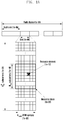
- FIG. 1A is a diagram illustrating a basic time-frequency resource structure for transmitting downlink data or control channels in an LTE system.
- the horizontal axis denotes the time
- the vertical axis denotes the frequency.
- the smallest transmission unit in the time domain is an OFDM symbol
- N symb OFDM symbols 1a-02 form a slot 1a-06
- 2 slots form a subframe 1a-05.
- Each slot spans 0.5 ms
- each subframe spans 1.0 ms.
- a radio frame 1a-14 is a time unit consisting of 10 subframes.
- the smallest transmission unit is a subcarrier, and the total system transmission bandwidth consists of N BW subcarriers 1a-04.
- the basic resource unit is a Resource Element (RE) 1a-12 indicated by an OFDM symbol index and a subcarrier index.
- a Resource Block (RB) (or Physical Resource Block (PRB) 1a-08 is defined by N symb consecutive OFDM symbols 1a-02 in the time domain and N RB consecutive subcarriers 1a-10 in the frequency domain.
- one RB 1a-08 consists of N symb x N RB REs 1a-12.
- the RB is the smallest data transmission unit.
- the data rate increases in proportion to the number of RBs scheduled to the terminal.
- 6 transmission bandwidths are defined.
- the downlink transmission bandwidth and uplink transmission bandwidth may differ from each other.
- the channel bandwidth denotes an RF bandwidth in comparison with the system transmission bandwidth.
- Table 1 shows the relationship between the system transmission bandwidth and channel bandwidth defined in the LTE standard. For example, an LTE system having a 10 MHz channel bandwidth uses the transmission bandwidth of 50 RBs. [Table 1] Channel bandwidth BW Channel [MHz] 1.4 3 5 10 15 20 Transmission bandwidth configuration N RB 6 15 25 50 75 100
- the downlink control information is transmitted in N OFDM symbols at the beginning of the subframe.
- N ⁇ 1, 2, 3 ⁇ . Accordingly, N value varies, at every subframe, with the control information amount to be transmitted.
- the control information includes a control channel transmission period indicator for indicating a number of OFDM symbols for conveying the control information, scheduling information for downlink or uplink data transmission, and an HARQ ACK/NACK signal.
- the downlink or uplink data scheduling information is transmitted from the base station to the terminal using Downlink Control Information (DCI).
- DCI Downlink Control Information
- the DCI is categorized into different DCI formats depending on the purpose, e.g., indicating UL grant for UL data scheduling or DL grant for DL data scheduling, indicating usage for control information that is small in size, indicating whether multiple antenna-based spatial multiplexing is applied, and indicating usage for power control.
- the DCI format 1 for DL grant is configured to include at least the following information.
- the DCI may be transmitted over a Physical Downlink Control Channel (PDCCH) or Enhanced PDCCH (EPDCCH) after undergoing a channel coding and modulation process.
- PDCCH transmission/reception may be understood as DCI transmission/reception on the PDCCH.
- Other channels may be understood in a similar way.
- the DCI is configured and transmitted through each independent PDCCH by being channel-coded after adding a CRC (Cyclic Redundancy Check) which is scrambled separately with a particular RNTI (Radio Network Temporary Identifier) (or a terminal identifier) for each terminal.
- CRC Cyclic Redundancy Check
- RNTI Radio Network Temporary Identifier
- a PDCCH may be mapped and transmitted during the control channel transmission period.
- the frequency-domain mapping location of the PDCCH may be determined by an ID of each terminal, and it may be spread throughout the entire system transmission band.
- Downlink data may be transmitted over a Physical Downlink Shared Channel (PDSCH) that is a physical channel for downlink data transmission.
- PDSCH Physical Downlink Shared Channel
- a PDSCH may be transmitted after the control channel transmission period, and the scheduling information such as the detailed mapping location in the frequency domain and the modulation scheme may be indicated by the DCI that is transmitted over the PDCCH.
- the base station uses MCS as part of the control information constituting the DCI to notifies the terminal of the modulation scheme applied to the PDSCH to be transmitted and the size of data (e.g., Transport Block Size (TBS)) to be transmitted.
- the MCS has a bitwidth of 5 or less or greater than 5.
- the TBS corresponds to the size given before channel coding for error correction is applied to the data (e.g., Transport Block (TB)) to be transmitted by the base station.
- the modulation schemes supported by the LTE system may include Quadrature Phase Shift Keying (QPSK), 16 Quadrature Amplitude Modulation (QAM), and 64QAM, and they have modulation orders (Q m ) 2, 4, and 6, respectively. That is, the QPSK modulation transmits 2 bits per symbol, the 16QAM transmits 4 bits per symbol, and the 64QAM transmits 6 bits per symbol. It may also be possible to use 256QAM or higher order modulation depending on the system.
- QPSK Quadrature Phase Shift Keying
- QAM 16 Quadrature Amplitude Modulation
- 64QAM modulation orders
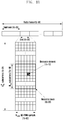
- FIG. 1B is a diagram illustrating a basic time-frequency resource structure for transmitting uplink data or control channels in an LTE-A system.
- the horizontal axis denotes the time
- the vertical axis denotes the frequency.
- the smallest transmission unit in the time domain is an SC-FDMA symbol
- N symb UL SC-FDMA symbols 1b-02 form a slot 1b-06.
- Two slots form a subframe 1b-05.
- the smallest transmission unit in the frequency domain is a subcarrier, and the total system transmission bandwidth consists of N BW subcarriers 1b-04.
- N BW may be proportional with the system transmission bandwidth.
- the basic resource unit is RE 1b-12, and each RE is defined by one SC-FDMA symbol index and one subcarrier index.
- a resource block (RB) pair 1b-08 is defined by N symb UL consecutive SC-FDMA symbols in the time domain and NscRB consecutive subcarriers in the frequency domain. Accordingly, one RB consists of N symb UL x N sc RB REs.
- the smallest data or control information transmission unit is RB.
- a physical uplink control channel (PUCCH) is mapped to a frequency region corresponding to one RB and transmitted during a time period of one subframe.
- the LTE standard defines a relationship between the PDSCH or the PDCCH/ EPDCCH carrying a semi-persistent scheduling (SPS) release and the PUCCH or physical uplink shared channel (PUSCH) carrying the HARQ ACK/NACK corresponding to the PDSCH, PDCCH, or EPDCCH.
- SPS semi-persistent scheduling
- PUSCH physical uplink shared channel
- the HARQ ACK/NACK corresponding to the PDSCH or the PDCCH or EPDCCH carrying the SPS release the PDSCH or the PDCCH or EPDCCH being transmitted at the (n-4) th subframe, is carried in the PUCCH or PUSCH being transmitted at the n th subframe.
- the LTE system employs an asynchronous HARQ scheme for DL HARQ. That is, if an eNB receives an HARQ NACK for initially transmitted data from a UE, it may freely determine a retransmission timing through a scheduling operation. If the UE fails to decode the received data, it stores the erroneous initial data and combines the buffered data with the retransmitted data.
- the UE receives a PDSCH carrying the DL data transmitted by the eNB at the n th subframe, it transmits UL control information including the HARQ ACK/NACK corresponding to the DL data to the eNB through the PUCCH or PUSCH at the (n+k) th subframe.
- k is determined differently depending on the duplex mode (i.e., FDD or time division duplex (TDD)) and subframe configuration in use by the LTE system.
- k is fixed to 4 in the FDD LTE system.
- k may vary according to the subframe configuration and subframe index in the TDD LTE system.
- the LTE system employs a synchronous HARQ scheme with a fixed data transmission timing for UL transmission distinct from the DL HARQ. That is, the UL-DL timing relationship between the PUSCH and PDCCH that is followed by the PUSCH and a physical hybrid indicator channel (PHICH) carrying the DL HARQ ACK/NACK corresponding to the PUSCH is fixed according to a rule as follows.
- PHICH physical hybrid indicator channel
- the UE If the UE receives a PDCCH carrying UL scheduling control information or a PHICH carrying a DL HARQ ACK/NACK from the eNB at the n th subframe, it transmits UL data through a PUSCH at the (n+k) th subframe based on the control information.
- k is determined differently depending on the duplex mode in use, i.e., FDD or TDD, and its configuration. For example, k is fixed to 4 in the FDD LTE system. Meanwhile, k may vary according to the subframe configuration and subframe index in the TDD LTE system.
- the eNB transmits a UL grant or a DL control signal and data to the UE at the n th subframe, the UE receives the UL grant or the DL control signal and data at the n th subframe. If UE receives a UL grant at the n th subframe, it transmits uplink data at the (n+4) th subframe.
- the UE If the UE receives a DL control signal and data at the n th subframe, it transmits an HARQ ACK/NACK corresponding to the DL data at the (n+4) th subframe. In this case, a time period given for the UE to prepare UL data transmission scheduled via the UL grant or transmission of HARQ ACK/NACK corresponding to the DL data becomes 3 ms, which is equal to the duration of three subframes.
- the UE receives the PHICH carrying the DL HARQ ACK/NACK from the eNB at the i th subframe and the DL HARQ ACK/NACK corresponding to the PUSCH transmitted by the UE at the (i+k) th subframe.
- k is determined differently depending of the duplex mode (i.e., FDD or TDD) and its configuration in use by the LTE system. For example, k is fixed to 4 in the FDD LTE system. Meanwhile, k may vary according to the subframe configuration and subframe index in the TDD LTE system.
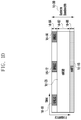
- FIGs. 1C and 1D are diagrams illustrating frequency-time resources allocated for transmitting data of eMBB, URLLC, and mMTC services being considered in the 5G or NR system.
- FIGs. 1C and 1D show how the frequency and time resources are allocated for information transmission in a system.
- the eMBB, URLLC, and mMTC data are mapped across the entire system frequency band 1c-00. If the URLLC data 1c-03, 1c-05, and 1c-07 are generated to be transmitted during the transmission of the eMBB data 1c-01 and mMTC data 1c-09 in specific frequency bands, parts of the eMBB data 1c-01 and mMTC data 1c-09 may be punctured such that the URLLC data 1c-03, 1c-05, and 1c-07 are inserted.
- the URLLC data 1c-03, 1c-05, and 1c-07 may occupy parts of the resources allocated for eMBB data 1c-01.
- the eMBB data may not transmitted on the overlapping frequency-time resources, which may degrade eMBB data transmission throughput. That is, in the above case, the resource allocation for the URLLC data transmission may cause eMBB data transmission failure.
- the system frequency band 1d-00 is divided into sub-bands 1d-02, 1d-04, and 1d-06 for data transmissions of different services.
- the sub-band configuration information may be preconfigured and transmitted from a base station to a terminal.
- the sub-bands 1d-02, 1d-04, and 1d-06 are allocated for eMBB data transmission, URLLC data transmission, and mMTC data transmission, respectively.
- the transmission time interval (TTI) for URLLC transmission may be shorter that the TTI for eMBB or mMTC transmission.
- the acknowledgement corresponding to the URLLC data may be transmitted more quickly than the acknowledgement corresponding to the eMBB or mMTC data, resulting in low latency information transmission/reception.
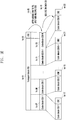
- FIG. 1E is a diagram illustrating a procedure for splitting a transport block into multiple code blocks and adding a CRC to the code blocks.
- a CRC 1e-03 may be added at the beginning or end of a transport block (TB) 1e-01 to be transmitted in uplink or downlink.
- the CRC may have a fixed length of 16 bits or 24 bits or a variable length varying with channel condition and may be used for determining whether the channel coding is successful.
- a block including the TB 1e-01 and the CRC 1e-03 may be split into multiple code blocks (CBs) 1e-07, 1e-09, 1e-11, and 1e-13 as denoted by reference number 1e-05.
- Each CB has a predetermined maximum size as far as possible and, in this case, the last CB 1e-13 may be smaller in size than the other code blocks. It may be possible to add 0s, random values, or 1s to the last CB to make the last CB to be equal in length to other CBs.
- the CRC may have a fixed length of 16 bits, 24 bits, or the like and may be used for determining whether the channel coding is successful.
- adding the CRC 1e-03 to the TB and adding the CRCs 1e-17, 1e-19, 1e-21, and 1e-23 to the respective CBs may be omitted depending on the type of the channel code to be applied to the CBs.
- adding the CRCs 1e-17, 1e-19, 1e-21, and 1e-23 to the respective CBs may be omitted.
- the CRCs 1e-17, 1e-19, 1e-21, and 1e-23 may be added to the CBs. Even in the case of using a polar code, it may be possible to omit adding any CRC.
- FIG. 1F is a diagram illustrating an outer code-based transmission method
- FIG. 1G is a diagram illustrating a structure of an outer code-based communication system.
- a TB is split into multiple CBs of which bits or symbols 1f-04 located at identical bit-positions are encoded with a second channel code to generate parity bits or symbols 1f-06 as denoted by reference number 1f-02.
- CRCs 1f-08 and 1f-10 may be respectively added to the CBs and parity CBs generated by encoding with the second channel code. It may be possible to add the CRC or not depending on the type of the channel code. For example, if a turbo code is used as a first channel code, the CRCs 1f-08 and 1f-10 are added and then the CBs and parity CBs may be encoded with the first channel code.
- the data to be transmitted passes the second channel coding encoder 1g-09.
- the channel coded for the second channel coding may include a Reed-Solomon code, a BCH code, a Raptor code, and a parity bit generation code.
- the bits or symbols that pass the second channel coding encoder 1g-09 pass a first channel coding encoder 1g-11.
- the channel code for the first channel coding may include a Convolutional code, an LDPC code, a Turbo code, and a Polar code.
- the receiver may process the received signals by means of a first channel coding decoder 1g-15 and a second channel coding decoder 1g-17 in serial order.
- the first and second channel coding decoders 1g-15 and 1g-17 may perform opposite operations of the first and second coding encoders 1g-11 and 1g-09, respectively.
- the first channel coding encoder 1g-11 and the first channel coding decoder 1g-05 are used in the channel coding block diagram with no second channel coding encoder and decoder. Even in the case of not using the outer code, the first channel coding decoder 1g-05 may have an identical configuration with that of the first channel coder 1g-11 for the case of using the outer coder.
- first type service an eMBB service
- eMBB service data are referred to as first type data.
- first type service and “first type data” are not limited to eMBB, and they may include other service types requiring a high speed data transmission or broadband transmission.
- second type service a URLLC service
- URLLC service data are referred to as second type data.
- second type service and second type data are not limited to URLLC, and they may include other service types requiring low latency, high reliability transmission, or low latency and high reliability transmission.
- third type service an mMTC service is referred to as third type service
- mMTC service data are referred to as third type data.
- third type service and “third type data” are not limited to mMTC, and they may include other service types requiring low speed, broad coverage, or low power transmission.
- the first type service may be understood as including or not including the third type service.
- the physical layer channel structures for transmitting the three types of services or data may differ from each other. For example, they may differ in at least one of TTI length, frequency resource allocation unit, control channel structure, and data mapping scheme.
- the terms "physical channel” and "signal" in use for LTE and LTE-A systems are used for explaining the proposed method and device.
- the principle of the present invention is applicable to other wireless communication systems as well as the LTE and LTE-A systems.
- the present invention defines communication operations between a terminal and a base station for transmitting the first, second, and third type services or data and proposes a method for serving the terminals in such a way of scheduling the different types of services or data for the respective terminals in the same system.
- the terms "first type terminal”, “second type terminal”, and “third type terminal” are intended to indicate the terminals for which the first, second, and third types of services or data, respectively, are scheduled.
- the first type terminal, second type terminal, and third type terminal may be identical with or different from each other.
- BS base station
- eNB evolved Node B
- terminal is intended to include a user equipment (UE), a mobile station (MS), a cellular phone, a smartphone, a computer, and a multimedia system with a communication function.
- UE user equipment
- MS mobile station
- uplink UL
- DL downlink
- UL uplink
- the present invention is applicable to other communication systems having a similar technical background and channel format.
- the present invention is applicable to the 5G mobile communication technology (5G new radio (NR)) under development for after LTE-A. It will be understood by those skilled in the art that the present invention can be applied even to other communication systems with a slight modification without departing from the spirit and scope of the present invention.
- 5G mobile communication technology 5G new radio (NR)
- the TTI denotes a unit of time for transmitting control and data signals or only the data signal.
- the TTI is equal in length to one subframe as a unit of time, i.e., 1 ms, in downlink.
- the TTI may denote a unit of time for transmitting a control and data signal or only the data signal in uplink.
- the TTI is a time unit of 1 ms equal in length with one subframe in both downlink and uplink.
- LTE employs a TTI of 1 ms, which is identical with the length of one subframe.
- An LTE system employing a TTI of 1 ms may support a UE operating with a TTI shorter than 1 ms (short-TTI UE).
- the 5G NR may employ a TTI shorter than 1 ms.
- the short-TTI UE is suitable for latency-sensitive services such as voice over LTE (VoLTE) and remote control services and is expected to be a means for realizing mission-critical IoT. It may also be expected that the short-TTI UE can be a means for realizing cellular-based mission-critical IoT.
- VoLTE voice over LTE
- remote control services is expected to be a means for realizing mission-critical IoT. It may also be expected that the short-TTI UE can be a means for realizing cellular-based mission-critical IoT.
- the terms "physical channel” and "signal" in use for the LTE or LTE-A system may be interchangeably used with the terms “data” or "control signal”.
- data or "control signal”.
- PDSCH is a physical channel carrying normal-TTI data, it may be referred to as normal-TTI data in the present invention.
- the uplink grant signal and the downlink data signal are referred to as first signal.
- the uplink data signal scheduled by the uplink grant and the HARQ ACK/NACK corresponding to a downlink data signal are referred to as second signal.
- the service type of the first signal may fall in three categories: eMBB, mMTC, and URLLC.
- the TTI length of the first signal denotes the time length for transmitting the first signal.
- the TTI length of the second signal denotes the time length for transmitting the second signal.
- the second signal transmission timing denotes the information indicating the timing at which the UE transmits the second signal and the base station receives the second signal, and it may be referred to as second signal transmission/reception timing.
- the term "higher layer signaling” denotes a signaling method for the base station to transmit a signal to the UE on a downlink data channel of the physical layer or for the UE to transmit a signal to the base station on an uplink data channel of the physical layer and may be referred to as RRC signaling or MAC control element (CE) signaling.
- transmit end may be used to indicate a base station in downlink and terminal in uplink.
- receive end may be used to indicate the terminal in downlink and the base station in uplink.
- sub-TB may be understood as a virtual concept indicating a bundle of one or more CBs.
- Embodiment 1 is directed to a method for splitting a TB into multiple CBs in such a way of splitting the TB into multiple sub-TBs and then splitting each sub-TB into multiple CBs.
- FIG. 1H is a diagram illustrating a method for splitting a TB into M sub-TBs as denoted by reference number 1h-01 and splitting each sub-TB into one or more CBs as denoted by reference number 1h-05.
- Reference number 1h-11 denotes a TB delivered from a higher layer to a physical layer. The physical layer regards the TB 1h-11 as data.
- a CRC 1h-13 may be added to the TB.
- the CRC 1h-13 may be generated with the TB 1h-11 and a cyclic generator polynomial, which may be defined in various manners.
- the CRC length L is 24, L may be set to 12, 16, 24, 32, 40, 48, 64, or the like.
- the TB is split into M sub-TBs as denoted by reference number 1h-01. That is, a transmission unit as a result of adding the CRC to the TB is divided into M sub-TBs 1h-21 and 1h-23.
- a CRC 1h-33 and 1h-37 is added as denoted by reference number 1h-03.
- the CRC being added to the sub-TB may differ from the CRC added to the TB in length or cyclic generator polynomial used in generating the CRC.
- a transmission unit as a result of adding the CRC to the sub-TB is split into multiple CBs 1h-41, 1h-42, 1h-45, and 1h-47 as denoted by reference number 1h-05.
- CRCs 1h-52, 1h-54, 1h-56, and 1h-58 are added, respectively, as denoted by reference number 1h-07.
- FIGs 1I , 1J , and 1K are diagrams illustrating alternatives to the method depicted in FIG. 1H .
- the CRC 1h-13 is added to the TB
- the CRC 1h-33 and 1h-37 to the sub-TBs
- the CRC 1h-52, 1h-54, 1h-56, and 1h-58 to the CBs
- no CRC is added to the TB in the method of FIG. 1I .
- This aims to reduce CRC overhead.
- No CRC is added to the sub-TBs in the method of FIG. 1J ; no CRC is added to the CBs in the method of FIG. 1K .
- Embodiment 1-1 is directed to a method for determining a number of sub-TBs and transmitting the information of M to a terminal in embodiment 1.
- the number of sub-TBs M may be determined and notified to the base station or UE in various manners. For example, it may be possible to determine M 1) by splitting a TB by the length of the TTI in which data are scheduled, 2) as being indicated by a specific bit of downlink control information (DCI), 3) as being indicated via RRC signaling, 4) based on the size of TB, 5) based on the total number of CBs, and using a combination of two or more of 1) to 5).
- DCI downlink control information
- Method 1) for determining M value based on the length of TTS in which data are scheduled is to determine the M value based on how many partial retransmission-available TTIs can be included in the TTI length is use for an initial transmission. For example, if the initial transmission is scheduled in a slot comprised of 7 OFDM symbols and a mini-slot consists of 2 or 3 symbols such that three 2-symbol or 3-symbol mini-slots can be included in one slot, M is set to 3.
- one TB may consist of 3 sub-TBs. It may also be possible to be set to a multiple of 2 that is closest to 3, the largest multiple of 2 that is less than 3, or the smallest multiple of 2 that is greater than 3. That is, M may be set to 2 or 4 in the above case. That is, the method for determining M based on the TTI length with which initial transmission is scheduled may be altered in various manners.
- Method 2) is for a base station to notify a terminal of the M value using specific bits of the DCI as a downlink control signal.
- the control signal may be a downlink assignment or an uplink grant.
- Method 3) is for the base station to notify the terminal of the M value via RRC signaling.
- the base station may transmit the M value information to the terminal via RRC signaling.
- Method 4 for determining the M value based on the TB size (TBS) is to determine the M value by comparing the TBS in use for initial transmission with a predetermined value. It is assumed that the maximum allowed size of a CB is Z and the TBS is B. It is also assumed that the length of the CRC being added to a sub-TB is L_sub_TB(L_ sub-TB ), the length of the CRC being added to a CB is L_CB(L CB ), and the length of the CRC being added to a TB is L_TB(L TB ). It is also assumed that the number of CBs is C and the number of sub-TBs is M.
- Method 5 for determining the M value based on the total number of CBs is to determine the M value by dividing the number of CBs for the initial transmission by a predetermined value. This may aim to fill one sub-TB with as similar a number of CBs as possible.
- Embodiment 1-2 is directed to a method for splitting a TB into sub-TBs and then into CBs as in embodiment 1.
- Embodiment 1-2 is an example of embodiment 1 and may be altered in various manners.
- the M value is determined based on the TTI length or indicated by a specific bit of DCI or via RRC signaling rather than determined based on the TBS or the number of CBs.
- N_1 and N_2 may be values that are greater than 0 and pre-agreed between a transmitter and a receiver, and they may denote CRC lengths for CB and sub-TB, respectively.
- ⁇ X ⁇ denotes an integer greater than X and ⁇ X ⁇ denotes the greatest integer less than X.
- the sub-TB may be understood as a virtual concept and a unit of a bundle of one or more CBs.
- the total number of CBs "C" may be determined as follows.
- a sub-TB consists of one CB
- the method may be modified such that a sub-TB consists of at least X CBs as follows.
- the CRC lengths of the sub-TB and CB, the numbers of the sub-TBs and CBs, and total number of bits B' of the data to be transmitted are determined.
- c rk denotes the k th bit of the r th CB.
- K+ is the smallest value included in a specific set among K values satisfying B' ⁇ C ⁇ K (the specific set may be a set including values pre-agreed between the transmitter and the receiver).
- NULL padding bits are inserted at the beginning by way of example in the above embodiment, and it may be possible to insert the padding bits in the middle or at the end.
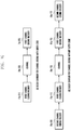
- FIG. 1L is a flowchart illustrating a method for a transmitter to split a TB into one or more sub-TBs and then one or more CBs and add CRCs to the sub-TB and CB.
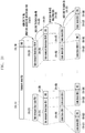
- FIG. 1M is a flowchart illustrating a method for a receiver to identify one or more sub-TBs and one or more CBs to decode a TB and determine whether the TB is decoded successfully using CRC added to the sub-TB and CB.
- Embodiment 2 is directed to a method for a terminal to determine a CRC length based on CRC length information transmitted by a base station and configure a CRC per CB based on the determined CRC length, which is described with reference to FIGs. 1N and 1O .
- the base station transmits to the terminal the length information of a CRC to be attached to each CB when downlink or uplink data transmission is performed.
- the CRC length information is 1) transmitted to the terminal via RRC signaling, 2) configured in transmission to which a partial retransmission technology is applied, or 3) transmitted via a specific bit of DCI.
- method 1) based on RRC signaling, if an RRC variable, such as long_CRC_PDSCH, is set to 1, it may be possible to apply a 32-bit or 48-bit CRC rather than 23-bit CRC, by way of example.
- RRC variable such as long_CRC_PDSCH
- method 2) based on application of the partial retransmission technology, it may be possible to set an RRC variable, such as partial_retransmission, to "active" or transmit DCI indicating the partial retransmission.
- method 3) based on a specific bit of DCI, it may be possible to set the specific bit to indicate whether to use a short CRC or a long length CRC.
- the short length CRC may have a length of 16 bits or 24 bits
- the long length CRC may have a length of 32 bits, 40 bits, or 48 bits.
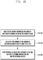
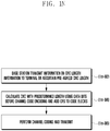
- FIG. 1N is a flowchart illustrating a procedure for a transmitter to provide CRC length information and perform a transmission using a CRC with a predetermined CRC length.
- the CRC length information may be pre-agreed between the base station and the terminal or transmitted from the base station to the terminal at step 1n-02.
- the base station calculates the CRC with a predetermined length based on data bits and adds the CRC to the CB at step 1n-04. It may be possible to use a predetermined cyclic generator polynomial for calculating the CRC.
- the CRC-added CB may be encoded with a channel code at step 1n-06.
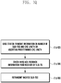
- FIG. 1O is a flowchart illustrating a procedure for a receiver to determine whether signal reception is successful using a CRC with a predetermined length that is obtained from CRC length information.
- the CRC length information may be pre-agreed between the base station and the terminal or transmitted from the base station to the terminal at step 1o-02.
- the receiver performs channel code decoding by CB at step 1o-04. After channel code decoding, the receiver checks the CRC with the predetermined length to determine, at step 1o-06, whether the decoding is successful.
- the CRC test may be performed with the cyclic generator polynomial used by the transmitted for generating the CRC.
- Embodiment 3 is directed to a method for determining a CRC length based on a service type of data being transmitted.
- the CRC length varies depending on whether the service being provided is an eMBB service, a URLLC service, or an mMTC service. It may be pre-agreed that the length of a CRC being added to a CB is 24 bits for the eMBB service, 32 bits or 40 bits for the URLLC service, and 16 bits, 24 bits, or 32 bits for the mMTC service. This may be because the required HARQ-ACK reliability varies with service.
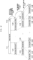
- Embodiment 4 is directed to a method for a transmitter to perform retransmissions by sub-TB based on HARQ-ACK information that is generated by a receiver by sub-TB and transmitted to the transmitter, which is described with reference to FIGs. 1P and 1Q .
- FIG. 1P is a flowchart illustrating a procedure for a receiver to transmit HARQ-ACK information by sub-TB.
- a base station and a terminal may share the information on a number of sub-TBs M and a CRC length at step 1p-02.
- the shared information may be transmitted from the base station to the UE via RRC signaling or DCI or shared according to a pre-agreed method.
- the receiver performs channel code decoding and checks the CRCs attached to CBs and sub-TBs to determine whether a specific sub-TB is successfully delivered at step 1p-04.
- the receiver transmits to the transmitter HARQ-ACK feedback information indicating whether the sub-TB is received successfully.
- the HARQ-ACK feedback information may include a number of bits corresponding to respective sub-TBs or bundles of sub-TBs. After transmitting the HARQ-ACK feedback information, the receiver may perform decoding on the sub-TBs that failed in the initial transmission under the assumption that the retransmission is performed by sub-TB.
- FIG. 1Q is a flowchart illustrating a procedure for a transmitter to perform retransmission by sub-TB based on HARQ-ACK information being transmitted by sub-TB.
- a base station and a terminal share the information on a number of sub-TBs M and a CRC length at step 1q-02.
- the shared information may be transmitted from the base station to the UE via RRC signaling or DCI or shared according to a pre-agreed method.
- the transmitter checks the HARQ-ACK feedback information transmitted by the receiver for transmission-failed sub-TBs at step 1q-04.
- the HARQ-ACK feedback information may include a number of bits corresponding to respective sub-TBs or bundles of sub-TBs.
- the transmitter retransmits the negatively acknowledged (NACK'ed) sub-TBs at step 1q-06.
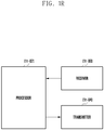
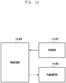
- the terminal and base station composed, each, of a transmitter, a receiver, and a processor for implementing the methods of the above embodiments are depicted in FIGs. 1R and 1S , respectively.
- the transmitter, receiver, and processor of each of the base station and the UE should operate as described in the respective embodiments.
- FIG. 1R is a block diagram illustrating a configuration of a UE according to an embodiment of the present invention.
- the UE may include a processor 1r-02, a receiver 1r-00, and a transmitter 1r-04.
- the receiver 1r-00 and the transmitter 1r-04 may be collectively referred to as a transceiver.
- the transceiver may transmit and receive signals to and from a base station.
- the signals may include control information and data.
- the transceiver may include a radio frequency (RF) transmitter for frequency-up-converting and amplifying a signal to be transmitted and an RF receiver for low-noise-amplifying and frequency-down-converting a received signal.
- RF radio frequency
- the transceiver may output the signal received over a radio channel to the processor 1r-02 and transmit the signal output from the processor 1r-02 over the radio channel.
- the processor 1r-02 may control overall operations of the UE. For example, the processor 1r-02 may control the receiver 1r-02 to receive a downlink data signal from a base station and determine whether the decoding succeeds by performing a CRC test by CB and sub-TB. Afterward, the transmitter 1r-04 may transmit HARQ-ACK feedback information by sub-TB.
- FIG. 1S is a block diagram illustrating a configuration of a base station according to an embodiment of the present invention.
- the base station may include a processor 1s-03, a receiver 1s-01, and a transmitter 1s-05.
- the receiver 1s-01 and the transmitter 1s-05 may be collectively referred to as a transceiver.
- the transceiver may transmit and receive signals to and from a terminal.
- the signals may include control information and data.
- the transceiver may include an RF transmitter for frequency-up-converting and amplifying a signal to be transmitted and an RF receiver for low-noise-amplifying and frequency-down-converting a received signal.
- the transceiver may output the signal received over a radio channel to the processor 1s-03 and transmit the signal output from the processor 1s-03 over the radio channel.
- the processor 1s-03 may control overall operations of the base station. For example, the processor 1s-03 may determine a number of sub-TBs M and control to generate and transmit corresponding information to a terminal. Afterward, the transmitter 1s-05 adds a CRC by CB and sub-TB and transmits the corresponding data, and the receiver 1s-01 receives HARQ-ACK information by sub-TB from the terminal.
- the processor 1s-03 may control to generate downlink control information (DCI) or a higher layer signaling signal including the number of sub-TBs and CRC length.
- DCI downlink control information
- the DCI or higher layer signaling signal may include information indicating whether the number of sub-TB and CRC length are included therein.
- the embodiments disclosed in the specification and drawings are proposed to help explain and understand the present invention rather than to limit the scope of the present invention. It is obvious to those skilled in the art that modifications and changes can be made thereto without departing from the spirit and scope of the present invention. If necessary, the embodiments may be combined in whole or in part.
- the base station and the UE may operate according to a combination of parts of embodiments 1 to 4 of the present invention.
- the embodiments been directed to the FDD LTE system
- the present invention can include alternative embodiments directed to other systems such as TDD LTE and 5G NR systems without departing from the technical sprit of the present invention.
Landscapes
- Engineering & Computer Science (AREA)
- Signal Processing (AREA)
- Computer Networks & Wireless Communication (AREA)
- Quality & Reliability (AREA)
- Mobile Radio Communication Systems (AREA)
Applications Claiming Priority (2)
| Application Number | Priority Date | Filing Date | Title |
|---|---|---|---|
| KR1020160144703A KR20180047886A (ko) | 2016-11-01 | 2016-11-01 | 무선 셀룰라 통신 시스템에서 데이터 전송 방법 및 장치 |
| PCT/KR2017/012080 WO2018084515A1 (fr) | 2016-11-01 | 2017-10-30 | Procédé et dispositif pour transmettre des données dans un système de communication cellulaire sans fil |
Publications (3)
| Publication Number | Publication Date |
|---|---|
| EP3522415A1 true EP3522415A1 (fr) | 2019-08-07 |
| EP3522415A4 EP3522415A4 (fr) | 2019-10-16 |
| EP3522415B1 EP3522415B1 (fr) | 2026-04-22 |
Family
ID=62076196
Family Applications (1)
| Application Number | Title | Priority Date | Filing Date |
|---|---|---|---|
| EP17867698.7A Active EP3522415B1 (fr) | 2016-11-01 | 2017-10-30 | Procédé et dispositif pour transmettre des données dans un système de communication cellulaire sans fil |
Country Status (6)
| Country | Link |
|---|---|
| US (3) | US11101928B2 (fr) |
| EP (1) | EP3522415B1 (fr) |
| KR (2) | KR20180047886A (fr) |
| CN (2) | CN109906575B (fr) |
| AU (1) | AU2017355887B2 (fr) |
| WO (1) | WO2018084515A1 (fr) |
Families Citing this family (22)
| Publication number | Priority date | Publication date | Assignee | Title |
|---|---|---|---|---|
| KR20180047886A (ko) * | 2016-11-01 | 2018-05-10 | 삼성전자주식회사 | 무선 셀룰라 통신 시스템에서 데이터 전송 방법 및 장치 |
| KR20180081421A (ko) | 2017-01-06 | 2018-07-16 | 삼성전자주식회사 | 무선 셀룰라 통신 시스템에서 제어정보 전송 방법 및 장치 |
| WO2018128394A1 (fr) | 2017-01-06 | 2018-07-12 | 삼성전자 주식회사 | Procédé et appareil pour émettre des informations de commande dans un système de communication cellulaire sans fil |
| US11190975B2 (en) * | 2017-02-13 | 2021-11-30 | Qualcomm Incorporated | Feedback techniques for wireless communications |
| KR102383906B1 (ko) | 2017-02-28 | 2022-04-08 | 삼성전자 주식회사 | 무선 셀룰라 통신 시스템에서 제어 및 데이터 신호의 사용자 구분 방법 및 장치 |
| WO2018164474A1 (fr) | 2017-03-08 | 2018-09-13 | 삼성전자 주식회사 | Procédé et appareil de commande et mise en correspondance de ressource d'informations de données dans un système de communication cellulaire sans fil |
| KR102320439B1 (ko) | 2017-03-08 | 2021-11-03 | 삼성전자 주식회사 | 무선 셀룰라 통신 시스템에서 제어 및 데이터 정보 자원 매핑 방법 및 장치 |
| US10887050B2 (en) * | 2017-03-24 | 2021-01-05 | Lg Electronics Inc. | Downlink signal reception method and user equipment, and downlink signal transmission method and base station |
| KR102339902B1 (ko) | 2017-05-02 | 2021-12-16 | 삼성전자 주식회사 | 무선 셀룰라 통신 시스템에서 제어 정보 전송 방법 및 장치 |
| WO2019061498A1 (fr) | 2017-09-30 | 2019-04-04 | Oppo广东移动通信有限公司 | Procédé d'indication d'ensemble de ressources de canal, dispositif terminal, et dispositif de réseau |
| KR102445007B1 (ko) | 2017-11-17 | 2022-09-19 | 지티이 코포레이션 | 무선 통신에서 전송 블록 크기를 결정하기 위한 방법, 장치 및 시스템 |
| CN109802765B (zh) * | 2017-11-17 | 2022-03-29 | 华为技术有限公司 | 一种应答信息发送方法及装置 |
| US20210391952A1 (en) * | 2018-11-01 | 2021-12-16 | Telefonaktiebolaget Lm Ericsson (Publ) | Harq bundling procedure for non-terrestrial networks |
| KR102808908B1 (ko) * | 2019-06-21 | 2025-05-19 | 삼성전자 주식회사 | 통신 시스템에서 사이드링크 피드백 송수신 방법 및 장치 |
| CN111650944B (zh) * | 2019-07-12 | 2021-05-04 | 西华大学 | 提高行车安全的汽车自动驾驶并线控制方法 |
| CN114531939B (zh) * | 2019-08-09 | 2025-05-06 | 优优卡姆株式会社 | 在无线通信系统中用于超低迟延和高可靠性通信的数据传输方法和与此相关装置 |
| KR20210020740A (ko) * | 2019-08-16 | 2021-02-24 | 삼성전자주식회사 | 네트워크 협력통신을 위한 상향링크 제어 정보 전송 방법 및 장치 |
| CN112532268B (zh) * | 2019-09-19 | 2023-10-20 | 中兴通讯股份有限公司 | 一种通信电路及通信设备 |
| US11792824B2 (en) * | 2020-03-30 | 2023-10-17 | Qualcomm Incorporated | Multicast feedback and retransmission for transport block grouping |
| CN119892299A (zh) * | 2020-09-07 | 2025-04-25 | 华为技术有限公司 | 一种通信方法及装置 |
| US20240195575A1 (en) * | 2021-04-07 | 2024-06-13 | Telefonaktiebolaget Lm Ericsson (Publ) | Data signalling for wireless communication |
| US20250293805A1 (en) * | 2024-03-14 | 2025-09-18 | Qualcomm Incorporated | Request based redundancy and early termination for outer coding |
Family Cites Families (21)
| Publication number | Priority date | Publication date | Assignee | Title |
|---|---|---|---|---|
| CN100586052C (zh) * | 2005-12-17 | 2010-01-27 | 华为技术有限公司 | 一种数据传输方法及系统 |
| CN101667900B (zh) * | 2008-09-02 | 2014-11-05 | 中兴通讯股份有限公司 | Harq反馈方法 |
| KR101633326B1 (ko) * | 2009-02-27 | 2016-06-24 | 엘지전자 주식회사 | 전송 방법 |
| US8737503B2 (en) | 2009-03-17 | 2014-05-27 | Futurewei Technologies, Inc. | System and method for multiple input, multiple output layer mapping |
| EP2413627A4 (fr) * | 2009-03-25 | 2015-01-21 | Fujitsu Ltd | Système de radiocommunication, dispositif de station mobile, dispositif de station de base et procédé de radiocommunication dans le système de radiocommunication |
| EP2244515A1 (fr) | 2009-04-23 | 2010-10-27 | Panasonic Corporation | Procédure de priorisation de canal logique pour générer plusieurs blocs de transport de liaison montante |
| US8537750B2 (en) * | 2009-06-02 | 2013-09-17 | Futurewei Technologies, Inc. | System and method for transport block size design for multiple-input, multiple-output (MIMO) in a wireless communications system |
| CN104301077B (zh) | 2013-07-16 | 2017-07-28 | 普天信息技术研究院有限公司 | 一种混合重传的方法 |
| US10033505B2 (en) * | 2014-07-31 | 2018-07-24 | Qualcomm Incorporated | Transmission of uplink control channels over an unlicensed radio frequency spectrum band |
| CN105515719B (zh) * | 2014-09-24 | 2019-04-26 | 中兴通讯股份有限公司 | 一种数据传输方法及装置 |
| US10219292B2 (en) * | 2014-10-24 | 2019-02-26 | Qualcomm Incorporated | Flexible multiplexing and feedback for variable transmission time intervals |
| CN105656598A (zh) * | 2014-11-24 | 2016-06-08 | 中兴通讯股份有限公司 | 控制信息的传输方法及装置 |
| WO2016099057A1 (fr) | 2014-12-16 | 2016-06-23 | 엘지전자 주식회사 | Procédé et dispositif mtc d'émission de dmrs de démodulation de données de liaison montante |
| US9992004B2 (en) * | 2015-02-03 | 2018-06-05 | Qualcomm Incorporated | Code block cluster level HARQ |
| US10270579B2 (en) | 2015-02-05 | 2019-04-23 | Qualcomm Incorporated | Efficient ACK/NACK transmission |
| US10574404B2 (en) * | 2016-04-22 | 2020-02-25 | Lg Electronics Inc. | Method for transmitting or receiving a HARQ-ACK signal in wireless communication system, and device therefor |
| CN113630215B (zh) | 2016-08-22 | 2024-04-16 | 三星电子株式会社 | 在无线蜂窝通信系统中用于提供初始接入过程的各种参数的方法和设备 |
| KR102683634B1 (ko) | 2016-08-22 | 2024-07-11 | 삼성전자 주식회사 | 통신 시스템에서 초기 접속을 수행하는 방법 및 장치 |
| US11252717B2 (en) * | 2016-09-02 | 2022-02-15 | Huawei Technologies Co., Ltd. | Co-existence of latency tolerant and low latency communications |
| WO2018071104A1 (fr) * | 2016-10-10 | 2018-04-19 | Intel IP Corporation | Équipement utilisateur (ue), nœud b évolué (enb) et procédés de demande de répétition automatique hybride (harq) dynamique |
| KR20180047886A (ko) * | 2016-11-01 | 2018-05-10 | 삼성전자주식회사 | 무선 셀룰라 통신 시스템에서 데이터 전송 방법 및 장치 |
-
2016
- 2016-11-01 KR KR1020160144703A patent/KR20180047886A/ko not_active Ceased
-
2017
- 2017-10-30 AU AU2017355887A patent/AU2017355887B2/en active Active
- 2017-10-30 EP EP17867698.7A patent/EP3522415B1/fr active Active
- 2017-10-30 US US16/346,696 patent/US11101928B2/en active Active
- 2017-10-30 CN CN201780068025.7A patent/CN109906575B/zh active Active
- 2017-10-30 WO PCT/KR2017/012080 patent/WO2018084515A1/fr not_active Ceased
- 2017-10-30 CN CN202210530817.4A patent/CN115134862B/zh active Active
-
2021
- 2021-08-23 US US17/409,382 patent/US11777649B2/en active Active
-
2023
- 2023-09-26 US US18/474,820 patent/US12199762B2/en active Active
-
2024
- 2024-04-04 KR KR1020240046101A patent/KR102940777B1/ko active Active
Also Published As
| Publication number | Publication date |
|---|---|
| WO2018084515A1 (fr) | 2018-05-11 |
| KR20180047886A (ko) | 2018-05-10 |
| US11101928B2 (en) | 2021-08-24 |
| CN109906575B (zh) | 2022-05-03 |
| EP3522415A4 (fr) | 2019-10-16 |
| EP3522415B1 (fr) | 2026-04-22 |
| CN115134862A (zh) | 2022-09-30 |
| AU2017355887A1 (en) | 2019-05-23 |
| CN109906575A (zh) | 2019-06-18 |
| AU2017355887B2 (en) | 2021-12-02 |
| US12199762B2 (en) | 2025-01-14 |
| KR20240049531A (ko) | 2024-04-16 |
| KR102940777B1 (ko) | 2026-03-19 |
| US20240014932A1 (en) | 2024-01-11 |
| US20190268095A1 (en) | 2019-08-29 |
| US20210385014A1 (en) | 2021-12-09 |
| CN115134862B (zh) | 2025-08-01 |
| US11777649B2 (en) | 2023-10-03 |
Similar Documents
| Publication | Publication Date | Title |
|---|---|---|
| US12199762B2 (en) | Method and device for transmitting coded data generated by splitting transport blocks in wireless cellular communication system | |
| US10498484B2 (en) | Method and apparatus for allowing different services to coexist in wireless cellular communication system | |
| KR102534044B1 (ko) | 이동 통신 시스템에서 데이터 디코딩 방법 및 장치 | |
| KR102746943B1 (ko) | 무선 셀룰라 통신 시스템에서 상향링크 데이터 및 제어신호 전송 타이밍 결정 방법 및 장치 | |
| KR102542993B1 (ko) | 무선 셀룰라 통신 시스템에서 제어 정보 송수신 방법 및 장치 | |
| EP3534581A1 (fr) | Procédé et appareil de transmission de liaison montante dans un système de communication cellulaire | |
| EP3567958A1 (fr) | Procédé et appareil d'émission et de réception d'informations pour fournir une pluralité de services de communication | |
| US12047948B2 (en) | Method and device for transmitting and receiving data based on scheduling restriction condition | |
| US11356988B2 (en) | Method and apparatus for mapping uplink control information in wireless communication system | |
| EP4518269A2 (fr) | Procédé et appareil de transmission ou de réception de données dans un système de communication | |
| EP3582559A1 (fr) | Procédé et appareil de commande de puissance de liaison montante dans un système de communication cellulaire sans fil | |
| KR20180049748A (ko) | 무선 셀룰라 통신 시스템에서 제어신호 검출 방법 및 장치 | |
| KR20240143997A (ko) | 무선 셀룰라 통신 시스템에서 하향링크 제어신호 복호 방법 및 장치 | |
| KR20190007365A (ko) | 무선 셀룰라 통신 시스템에서 짧은 전송 시간 구간을 이용한 제어 및 데이터 신호 송수신 방법 및 장치 |
Legal Events
| Date | Code | Title | Description |
|---|---|---|---|
| STAA | Information on the status of an ep patent application or granted ep patent |
Free format text: STATUS: THE INTERNATIONAL PUBLICATION HAS BEEN MADE |
|
| PUAI | Public reference made under article 153(3) epc to a published international application that has entered the european phase |
Free format text: ORIGINAL CODE: 0009012 |
|
| STAA | Information on the status of an ep patent application or granted ep patent |
Free format text: STATUS: REQUEST FOR EXAMINATION WAS MADE |
|
| 17P | Request for examination filed |
Effective date: 20190501 |
|
| AK | Designated contracting states |
Kind code of ref document: A1 Designated state(s): AL AT BE BG CH CY CZ DE DK EE ES FI FR GB GR HR HU IE IS IT LI LT LU LV MC MK MT NL NO PL PT RO RS SE SI SK SM TR |
|
| AX | Request for extension of the european patent |
Extension state: BA ME |
|
| A4 | Supplementary search report drawn up and despatched |
Effective date: 20190918 |
|
| RIC1 | Information provided on ipc code assigned before grant |
Ipc: H04L 1/00 20060101AFI20190912BHEP Ipc: H04L 1/18 20060101ALI20190912BHEP |
|
| DAV | Request for validation of the european patent (deleted) | ||
| DAX | Request for extension of the european patent (deleted) | ||
| STAA | Information on the status of an ep patent application or granted ep patent |
Free format text: STATUS: EXAMINATION IS IN PROGRESS |
|
| 17Q | First examination report despatched |
Effective date: 20210506 |
|
| GRAP | Despatch of communication of intention to grant a patent |
Free format text: ORIGINAL CODE: EPIDOSNIGR1 |
|
| STAA | Information on the status of an ep patent application or granted ep patent |
Free format text: STATUS: GRANT OF PATENT IS INTENDED |
|
| INTG | Intention to grant announced |
Effective date: 20250718 |
|
| GRAJ | Information related to disapproval of communication of intention to grant by the applicant or resumption of examination proceedings by the epo deleted |
Free format text: ORIGINAL CODE: EPIDOSDIGR1 |
|
| STAA | Information on the status of an ep patent application or granted ep patent |
Free format text: STATUS: EXAMINATION IS IN PROGRESS |
|
| GRAP | Despatch of communication of intention to grant a patent |
Free format text: ORIGINAL CODE: EPIDOSNIGR1 |
|
| STAA | Information on the status of an ep patent application or granted ep patent |
Free format text: STATUS: GRANT OF PATENT IS INTENDED |
|
| INTC | Intention to grant announced (deleted) | ||
| INTG | Intention to grant announced |
Effective date: 20251126 |
|
| GRAS | Grant fee paid |
Free format text: ORIGINAL CODE: EPIDOSNIGR3 |
|
| GRAA | (expected) grant |
Free format text: ORIGINAL CODE: 0009210 |
|
| STAA | Information on the status of an ep patent application or granted ep patent |
Free format text: STATUS: THE PATENT HAS BEEN GRANTED |
|
| AK | Designated contracting states |
Kind code of ref document: B1 Designated state(s): AL AT BE BG CH CY CZ DE DK EE ES FI FR GB GR HR HU IE IS IT LI LT LU LV MC MK MT NL NO PL PT RO RS SE SI SK SM TR |
|
| REG | Reference to a national code |
Ref country code: CH Ref legal event code: F10 Free format text: ST27 STATUS EVENT CODE: U-0-0-F10-F00 (AS PROVIDED BY THE NATIONAL OFFICE) Effective date: 20260422 Ref country code: GB Ref legal event code: FG4D |