EP3522618B1 - Dispositif utilisateur et station de base - Google Patents
Dispositif utilisateur et station de base Download PDFInfo
- Publication number
- EP3522618B1 EP3522618B1 EP17855281.6A EP17855281A EP3522618B1 EP 3522618 B1 EP3522618 B1 EP 3522618B1 EP 17855281 A EP17855281 A EP 17855281A EP 3522618 B1 EP3522618 B1 EP 3522618B1
- Authority
- EP
- European Patent Office
- Prior art keywords
- transmission power
- base station
- user equipment
- power
- frequency band
- Prior art date
- Legal status (The legal status is an assumption and is not a legal conclusion. Google has not performed a legal analysis and makes no representation as to the accuracy of the status listed.)
- Active
Links
Images




Classifications
-
- H—ELECTRICITY
- H04—ELECTRIC COMMUNICATION TECHNIQUE
- H04W—WIRELESS COMMUNICATION NETWORKS
- H04W52/00—Power management, e.g. Transmission Power Control [TPC] or power classes
- H04W52/04—Transmission power control [TPC]
- H04W52/30—Transmission power control [TPC] using constraints in the total amount of available transmission power
- H04W52/36—Transmission power control [TPC] using constraints in the total amount of available transmission power with a discrete range or set of values, e.g. step size, ramping or offsets
- H04W52/367—Power values between minimum and maximum limits, e.g. dynamic range
-
- H—ELECTRICITY
- H04—ELECTRIC COMMUNICATION TECHNIQUE
- H04B—TRANSMISSION
- H04B1/00—Details of transmission systems, not covered by a single one of groups H04B3/00 - H04B13/00; Details of transmission systems not characterised by the medium used for transmission
- H04B1/02—Transmitters
- H04B1/04—Circuits
-
- H—ELECTRICITY
- H04—ELECTRIC COMMUNICATION TECHNIQUE
- H04W—WIRELESS COMMUNICATION NETWORKS
- H04W36/00—Hand-off or reselection arrangements
- H04W36/0005—Control or signalling for completing the hand-off
- H04W36/0083—Determination of parameters used for hand-off, e.g. generation or modification of neighbour cell lists
- H04W36/0085—Hand-off measurements
-
- H—ELECTRICITY
- H04—ELECTRIC COMMUNICATION TECHNIQUE
- H04W—WIRELESS COMMUNICATION NETWORKS
- H04W52/00—Power management, e.g. Transmission Power Control [TPC] or power classes
- H04W52/04—Transmission power control [TPC]
- H04W52/38—TPC being performed in particular situations
-
- H—ELECTRICITY
- H04—ELECTRIC COMMUNICATION TECHNIQUE
- H04W—WIRELESS COMMUNICATION NETWORKS
- H04W74/00—Wireless channel access
- H04W74/08—Non-scheduled access, e.g. ALOHA
-
- H—ELECTRICITY
- H04—ELECTRIC COMMUNICATION TECHNIQUE
- H04W—WIRELESS COMMUNICATION NETWORKS
- H04W52/00—Power management, e.g. Transmission Power Control [TPC] or power classes
- H04W52/04—Transmission power control [TPC]
- H04W52/06—TPC algorithms
- H04W52/14—Separate analysis of uplink or downlink
- H04W52/146—Uplink power control
-
- H—ELECTRICITY
- H04—ELECTRIC COMMUNICATION TECHNIQUE
- H04W—WIRELESS COMMUNICATION NETWORKS
- H04W52/00—Power management, e.g. Transmission Power Control [TPC] or power classes
- H04W52/04—Transmission power control [TPC]
- H04W52/38—TPC being performed in particular situations
- H04W52/40—TPC being performed in particular situations during macro-diversity or soft handoff
-
- H—ELECTRICITY
- H04—ELECTRIC COMMUNICATION TECHNIQUE
- H04W—WIRELESS COMMUNICATION NETWORKS
- H04W52/00—Power management, e.g. Transmission Power Control [TPC] or power classes
- H04W52/04—Transmission power control [TPC]
- H04W52/38—TPC being performed in particular situations
- H04W52/50—TPC being performed in particular situations at the moment of starting communication in a multiple access environment
Definitions
- the present invention relates to a radio communication system.
- PC3 power class 3
- PC2 power class 2
- Non-Patent Document 6 relates to protocol specifications in the content of the 3rd Generation Partnership Project and particularly relates to the Radio Resource Control protocol for the radio interface between user equipment and E-UTRAN as well as for the radio interface between relay node and E-UTRAN.
- Non-Patent Document 7 relates to the minimum radio frequency characteristics and minimum performance requirements for E-UTRA user equipment.
- Non-Patent Document 8 relates to the impact of high power user equipment to existing 2.5Ghz networks.
- Patent Document 1 relates to a method and an apparatus for user equipment power class adaptation for coverage extension in Long Term Evolution to mitigate interference.
- Patent Document 2 relates to a mobile radio communication device that can dynamically change its power class according to the battery voltage of the device.
- the base station is able to determine whether the user equipment supports transmission power higher than PC3 based on capability information acquired from the user equipment, and the base station is able to control the user equipment which supports PC1 or PC2 so that the transmission power is less than or equal to that of PC3.
- the capability information is acquired after a radio resource control (RRC) connection. Accordingly, in a random access procedure prior to the RRC connection, the user equipment may output transmission power higher than that of PC3.
- RRC radio resource control
- 3GPP TS 36.101 the following is defined for a user equipment corresponding to PC2 that operates in Band 41: when an information element (IE) P-max is configured to 23 dBm or less in a cell and a time division duplex (TDD) frame configuration with a high uplink allocation ratio is 0 or 6, regulations for PC2 are not applicable, P PowerClass is reconfigured to 23 dBm, and regulations for PC3 are applied to the user equipment.
- IE information element
- TDD time division duplex
- the user equipment corresponding to PC2 has P-max that is equal to or less than 23 dBm or when the user equipment accesses a network to which a TDD frame configuration of 0 or 6 is applied, the user equipment is un able to operate according to PC2, and the user equipment is required to fall back from PC2 to PC3.
- an object of the present invention is to provide a power control technique for user equipment supporting high transmission power.
- an aspect of the present invention relates to user equipment as defined in claim 1, to a method as defined by claim 2 and to a system as defined by claim 3.
- a power control technique for user equipment supporting high transmission power can be provided.
- the following embodiment discloses a user equipment that supports a power class (PC1 or PC2) higher than a default power class such as PC3.
- PC1 or PC2 a power class
- PC3 a default power class
- the user equipment When accessing a base station in a frequency band having a power class lower than a high power class that is supported as a default power class, the user equipment performs a random access procedure for the base station, using transmission regulations for the default power class in the frequency band and transmission power that is equal to or less than the maximum transmission power of the default power class.
- the user equipment when the maximum transmission power of the frequency band of an access destination is not notified by the base station through system information or a handover instruction, the user equipment performs control such that user equipment transmission power is the maximum transmission power of the default power class, according to the regulations for the default power class of the frequency band.
- the user equipment may perform control such that the user equipment transmission power is the maximum transmission power of the high power class according to the regulations for the high power class of the frequency band.
- the user equipment may perform control such that the user equipment transmission power is the lower of the maximum transmission power of the low power class and the notified maximum transmission power according to the regulations for the low power class of the frequency band.
- the transmission regulations for the user equipment defined for each power class of the frequency band include an adjacent channel leakage ratio (ACLR), adjacent channel selectivity (ACS), a reference sensitivity power level (REFSENS), a spectrum emission mask (SEM), and maximum power reduction (MPR) (Non-Patent Document 5).
- the user equipment that supports the high power class can access the base station, using transmission power that is allowed by a cell of the base station, which is an access destination, and the transmission regulations.
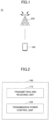
- FIG. 1 is a diagram schematically illustrating the radio communication system according to the embodiment.
- a radio communication system 10 includes a user equipment 100 and a base station 200.
- the radio communication system 10 may be typically a radio communication system based on a 3rd generation partnership project (3GPP) standard, such as an LTE system, an LTE-Advanced system, or a 5G system.
- 3GPP 3rd generation partnership project
- the radio communication system 10 according to the invention is not limited thereto and may be, for example, universal mobile telecommunications system (UMTS) or UMTS enhancement or may be a variation in the LTE system, such as an LTE single-cluster, an LTE multicluster, a UL inter-band CA, a UL intra-band contiguous CA, a UL intra-band non-contiguous CA, or Dual Connectivity.
- UMTS universal mobile telecommunications system
- UMTS universal mobile telecommunications system
- UMTS universal mobile telecommunications system
- UMTS universal mobile telecommunications system
- UMTS universal mobile telecommunications system
- the user equipment 100 wirelessly communicates with the base station 200 through a cell or a frequency band that is provided by the base station 200 according to the 3GPP standard such as LTE, LTE-Advanced, and/or 5G.
- the user equipment 100 may be any appropriate information processing device with a wireless communication function, such as a smart phone, a mobile phone, a tablet computer, a mobile router, or a wearable terminal.
- the base station 200 establishes a wireless link to the user equipment 100 through a cell or a frequency band according to the 3GPP standard, such as LTE, LTE-Advanced, and/or 5G, to transmit a downlink (DL) packet, which has been received from a higher layer node and/or a server communicably connected to a core network (not depicted), to the user equipment 100, and the base station 200 transmits an uplink (UL) packet received from the user equipment 100 to the server.
- the 3GPP standard such as LTE, LTE-Advanced, and/or 5G
- Fig. 2 is a block diagram illustrating the functional configuration of the user equipment according to the embodiment.
- the user equipment 100 supports high transmission power, such as PC1 or PC2, in a certain frequency band and includes a transmitting and receiving unit 110 and a transmission power control unit 120.
- the transmitting and receiving unit 110 transmits and receives radio signals to and from the base station 200. Specifically, the transmitting and receiving unit 110 transmits and receives various radio signals, such as those of uplink/downlink control channels and/or those of uplink/downlink data channels, to and from the base station 200.
- the transmission power control unit 120 controls transmission power to the base station 200.
- the transmission power control unit 120 performs control such that transmission from the user equipment to the base station 200 is performed according to transmission regulations for the default power class of the frequency band and transmission power is equal to or less than the default power class.
- the transmission power control unit 120 applies the default power class at the time a random access (RA) procedure for the base station 200 starts.
- RA random access
- the transmission power control unit 120 determines the power class and/or the maximum transmission power applied in the frequency band on the basis of individual signaling or the system information received from the base station 200 and determines the power class to be applied in the frequency band when a connection request (RA preamble) is transmitted to the base station 200.
- RA preamble connection request
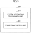
- Fig. 3 is a block diagram illustrating the functional configuration of the base station according to the embodiment.
- the base station 200 includes a system information transmission unit 210 and a connection control unit 220.
- the system information transmission unit 210 transmits system information.
- the system information may include, for example, the maximum transmission power and/or the power class that is applied in the frequency band provided by the base station 200.
- the system information transmission unit 210 periodically broadcasts the value of P-max or the power class applied in the frequency band, using System Information Block Type 1.
- the connection control unit 220 controls a radio connection to the user equipment 100. Specifically, when an RA preamble is received from the user equipment 100, the connection control unit 220 transmits an RA response to the user equipment 100 to establish a radio connection or an RRC connection to the user equipment 100. After the radio connection is established, the connection control unit 220 performs, for example, mobility control to manage the radio connection to the user equipment 100 and notifies the user equipment 100 of the value of P-max or the power class applied in the frequency band, using individual signaling.
- the transmission power control unit 120 controls the transmission regulations and the transmission power required to access the base station 200, according to the maximum transmission power (for example, P-max) notified by the base station 200.
- the transmission power control unit 120 may control the transmitting and receiving unit 110 such that an access request to the frequency band is transmitted to the base station 200, which is the access destination, with the maximum transmission power, according to the transmission regulations for a low power class, such as PC3, in the frequency band.
- a high power class such as PC1 or PC2
- the transmission power control unit 120 may control the transmitting and receiving unit 110 such that an access request to the frequency band is transmitted to the base station 200, which is the access destination, with the maximum transmission power, according to the transmission regulations for a low power class, such as PC3, in the frequency band.
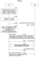
- Step S101 the user equipment 100 supports PC2 with a maximum transmission power of 26 dBm in a band X having PC3 with a maximum transmission power of 26 dBm as the default power class.
- Step S102 the user equipment 100 tries to camp on the cell in the band X.
- the base station 200 returns an RA response to the RA request.
- Step S107 the base station 200 establishes an RRC connection to the user equipment 100.
- Step S108 the connection control unit 220 transmits UE capability Enquiry to the user equipment 100 in order to request capability information.
- the transmitting and receiving unit 110 notifies the base station 200 that the user equipment 100 supports PC2 with a higher power than PC3.
- the connection control unit 220 may instruct the user equipment 100 to apply PC2.
- the user equipment 100 may perform the RA procedure for the cell with a maximum transmission power of 26 dBm, according to the regulations for PC2.
- the transmission power control unit 120 may control the transmitting and receiving unit 110 such that an access request to the frequency band is transmitted to a target base station 200 with the maximum transmission power, according to the regulations for the low power class such as PC3.
- Step S201 the user equipment 100 supports PC2 with a maximum transmission power of 26 dBm in the band X having PC3 with a maximum transmission power of 23 dBm as the default power class.
- Step S202 the user equipment 100 receives a handover instruction (RRC Connection Reconfiguration with mobility Control Info) from cell #1 of the source base station 200 to cell #1 of the target base station 200.
- the base station 200 returns an RA response to the RA request.
- the user equipment 100 transmits a handover completion notice (RRC Connection Reconfiguration Complete) indicating that an RRC connection to the base station 200 has been established.
- RRC Connection Reconfiguration Complete handover completion notice
- the transmission power control unit 120 controls transmission power required to access the base station 200 according to the power class notified by the base station 200.
- the transmission power control unit 120 may control the transmitting and receiving unit 110 such that an access request to the frequency band is transmitted to the base station 200, which is the access destination, with the lower of the low power class (PC3) and the maximum transmission power (P-max), according to the regulations for the low power class.
- PC3 low power class
- P-max maximum transmission power
- Step S301 the user equipment 100 supports PC2 with a maximum transmission power of 26 dBm in a band X having PC3 with a maximum transmission power of 26 dBm as the default power class.
- Step S202 the user equipment 100 tries to camp on the cell in the band X.
- Step S203 the transmitting and receiving unit 110 receives System Information Block Type 1 indicating the power class PC3 broadcasted from the system information transmission unit 210.
- Step S304 the transmission power control unit 120 compares the maximum transmission power (23 dBm) of PC3 with P-Max and applies the lower of the low power class (PC3) and the maximum transmission power (P-max) in the frequency band according to transmission regulations (for example, Spectrum Emission Mask) for PC3 in the band X.
- the transmission power control unit 120 transmits a random access request (RA preamble) to the base station 200 with the determined transmission power, according to the transmission regulations for PC3.
- Step S306 the base station 200 returns an RA response to the RA request.
- Step S307 the base station 200 establishes an RRC connection to the user equipment 100.
- Step S308 the connection control unit 220 transmits UE capability Enquiry to the user equipment 100 in order to request capability information.
- the transmitting and receiving unit 110 notifies the base station 200 that the user equipment 100 supports PC2 with a higher power than PC3.
- the connection control unit 220 may instruct the user equipment 100 to apply PC2.
- the user equipment 100 may perform the RA procedure for the cell with a maximum transmission power of 26 dBm, according to the regulations for PC2.
- the transmission power control unit 120 may control the transmitting and receiving unit 110 such that an access request to the frequency band is transmitted to a target base station 200 with the lower of the low power class (PC3) and the maximum transmission power (P-max), according to the regulations for the low power class.
- PC3 low power class
- P-max maximum transmission power
- Step S401 the user equipment 100 supports PC2 of 26 dBm in the band X having PC3 of 23 dBm as the default power class.
- Step S402 the user equipment 100 receives a handover instruction (RRC Connection Reconfiguration with mobility Control Info) from cell #1 of the source base station 200 to cell #1 of the target base station 200.
- the handover instruction indicates that cell #1 of the target base station 200 is in the power class PC3.
- Step S403 the transmission power control unit 120 compares the maximum transmission power (26 dBm) of PC3 with P-Max and applies the lower of the low power class (PC3) and the maximum transmission power (P-max) in the frequency band according to the transmission regulations (for example, Spectrum Emission Mask) for PC3 in the band X.
- the transmission power control unit 120 transmits a random access request (RA preamble) to the base station 200 with the determined transmission power, according to the transmission regulations for PC3.
- Step S405 the base station 200 returns an RA response to the RA request.
- Step S406 the base station 200 transmits a handover completion notice (RRC Connection Reconfiguration Complete) indicating that an RRC connection to the base station 200 has been established.
- RRC Connection Reconfiguration Complete indicating that an RRC connection to the base station 200 has been established.
- a transmission power control process is described with reference to Figs. 8 to 10 .
- the default power class for example, 23 dBm of PC3
- the information element P-max is not broadcasted in the frequency band through system information and the information element P-max is broadcasted only in a specific area, such as a hospital, in which the maximum transmission power is lower than the default power class. Therefore, in a network in which a power class (for example, 31 dBm of PC1 or 26 dBm of PC2) higher than the default power class is not allowed, it is not preferable to broadcast the information element P-max.
- the transmission power control unit 120 may control the transmission power of the user equipment such that the transmission power is the maximum transmission power of the default power class, according to the transmission regulations for the default power class of the frequency band.
- the transmission power control unit 120 may control the transmission power of the user equipment such that the transmission power is the maximum transmission power of the high power class, according to the transmission regulations for the high power class of the frequency band.
- the transmission power control unit 120 may control the transmission power of the user equipment such that the transmission power is the lower of the default power class and the maximum transmission power, according to the transmission regulations for the high power class of the frequency band.
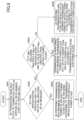
- Fig. 8 is a flowchart illustrating the transmission power control process performed by the user equipment according to the third embodiment
- the user equipment 100 changes from an idle state to a connected state in a cell having PC3 as the default power class or is handed over to the cell.
- the user equipment 100 determines whether the maximum transmission power P-max has been notified through the system information (for example, SIB1, SIB3, or SIB5) of the cell or the maximum transmission power P-max has been notified through a handover message.
- the system information for example, SIB1, SIB3, or SIB5
- Step S503 the user equipment 100 transmits an uplink signal including a connection request (RA preamble) to the base station 200 with the maximum transmission power of PC3 according to the transmission requirements of the default power class (PC3) of the frequency band.
- RA preamble connection request
- Step S504 the user equipment 100 determines whether P-max including multiple P-max/NS has been broadcasted and the value of P-max is greater than the default power class.
- Step S505 the user equipment 100 transmits an uplink signal including a connection request (RA preamble) to the base station 200 with the maximum transmission power of the high power class (PC1 or PC2) according to the transmission requirements of the high power class of the frequency band.
- RA preamble connection request
- Step S506 the user equipment 100 transmits an uplink signal including a connection request (RA preamble) to the base station 200 with the lower of P-max and the default power class (PC3) according to the transmission requirements of the default power class of the frequency band.
- RA preamble connection request
- PC3 default power class
- Fig. 9 is a sequence diagram illustrating an initial access process according to the third embodiment .
- a case in which P-max is not notified through the system information is described.
- Step S601 the user equipment 100 supports PC2 of 26 dBm in the band X having PC3 of 23 dBm as the default power class.
- Step S602 the user equipment 100 tries to camp on a cell in the band X.
- Step S603 the transmitting and receiving unit 110 receives System Information Block Type 1 broadcasted from the system information transmission unit 210. In this example, it is assumed that the information element P-max is not notified through the system information.
- Step S604 the transmission power control unit 120 applies the transmission regulations (for example, Spectrum Emission Mask) for the default power class PC3 of the band X in the frequency band.
- the base station 200 returns an RA response to the RA request.
- the base station 200 establishes an RRC connection to the user equipment 100.
- Step S608 the connection control unit 220 transmits UE capability Enquiry to the user equipment 100 in order to request capability information.
- Step S609 the transmitting and receiving unit 110 notifies the base station 200 that the user equipment 100 supports PC2 with a higher power than PC3.
- Step S610 the connection control unit 220 instructs the user equipment 100 to apply PC2, using RRC Connection Reconfiguration.
- Step S611 the user equipment 100 applies the regulations for PC2.
- Step S612 the user equipment 100 transmits RRC Connection Reconfiguration Complete to the base station 200.
- the user equipment 100 may perform the transmission power control process described with reference to Fig. 8 , regardless of the notified UE capability.
- Fig. 10 is a diagram illustrating an example of signaling according to an embodiment
- the transmission power control unit 120 may apply the transmission regulations for the default transmission power class of the frequency and may configure predetermined transmission power.
- each functional block may be implemented by one device that is physically and/or logically coupled or by a plurality of devices that are physically and/or logically separated from each other and are connected directly and/or indirectly (for example, in a wired manner and/or wirelessly).
- the user equipment 100 and the base station 200 may function as a computer that performs the processes of a wireless communication method according to the invention.
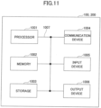
- Fig. 13 is a block diagram illustrating the hardware configuration of the user equipment 100 and the base station 200 according to the embodiment of the invention.
- Each of the user equipment 100 and the base station 200 may be physically configured as a computer device including, for example, a processor 1001, a memory 1002, a storage 1003, a communication device 1004, an input device 1005, an output device 1006, and a bus 1007.
- the term "device” can be substituted with, for example, a circuit, an apparatus, and a unit.
- the hardware configuration of the user equipment 100 and the base station 200 may include one or a plurality of devices illustrated in Fig. 11 or may not include some of the devices.
- Each function of the user equipment 100 and the base station 200 may be implemented by the following process: predetermined software (program) is read onto hardware, such as the processor 1001 or the memory 1002, and the processor 1001 performs an operation to control the communication of the communication device 1004 or the reading and/or writing of data from and/or to the memory 1002 and the storage 1003.
- predetermined software program
- the processor 1001 performs an operation to control the communication of the communication device 1004 or the reading and/or writing of data from and/or to the memory 1002 and the storage 1003.
- the processor 1001 operates, for example, an operating system to control the overall operation of the computer.
- the processor 1001 may be a central processing unit (CPU) including, for example, an interface with peripheral devices, a control device, an arithmetic device, and a register.
- CPU central processing unit
- each of the above-mentioned components may be implemented by the processor 1001.
- the processor 1001 reads a program (program code), a software module, or data from the storage 1003 and/or the communication device 1004 to the memory 1002 and performs various types of processes according to the program, the software module, or the data.
- a program that causes a computer to perform at least some of the operations described in the embodiments is used as the program.
- the processes performed by each component of the user equipment 100 and the base stations 200 and 201 may be implemented by a control program that is stored in the memory 1002 and is executed by the processor 1001.
- Other functional blocks may be implemented by the same method as described above.
- the above-mentioned various processes are performed by one processor 1001. However, the processes may be simultaneously or sequentially performed by two or more processors 1001.
- the processor 1001 may be mounted with one or more chips.
- the program may be transmitted from the network through an electric communication line.
- the memory 1002 is a computer-readable recording medium and may include, for example, at least one of a read only memory (ROM), an erasable programmable ROM (EPROM), an electrically erasable programmable ROM (EEPROM), and a random access memory (RAM).
- the memory 1002 may also be referred to as, for example, a register, a cache, or a main memory (main storage device).
- the memory 1002 can store, for example, a program (program code) and a software module that can be executed to perform the wireless communication method according to the embodiment of the invention.
- the storage 1003 is a computer-readable recording medium and may include, for example, at least one of an optical disk, such as a compact disc ROM (CD-ROM), a hard disk drive, a flexible disk, a magneto-optical disk (for example, a compact disc, a digital versatile disc, or a Blu-ray (registered trademark) disc), a smart card, a flash memory (for example, a card, a stick, or a key drive), a floppy (registered trademark) disk, and a magnetic strip.
- the storage 1003 may also be referred to as an auxiliary storage device.
- the above-mentioned storage medium may be, for example, a database, a server, and other proper media including the memory 1002 and/or the storage 1003.
- the communication device 1004 is hardware (transmitting and receiving device) for communicating with the computer through a wired and/or wireless network and is also referred to as, for example, a network device, a network controller, a network card, or a communication module.
- a network device for example, a network controller, a network card, or a communication module.
- each of the above-mentioned components may be implemented by the communication device 1004.
- the input device 1005 is an input unit (for example, a keyboard, a mouse, a microphone, a switch, a button, or a sensor) that receives an input from the outside.
- the output device 1006 is an output device (for example, a display, a speaker, or an LED lamp) that performs an output process to the outside.
- the input device 1005 and the output device 1006 may be integrated with each other (for example, a touch panel).
- the bus 1007 may be a single bus or the devices may be connected to each other by different buses.
- the user equipment 100 and the base station 200 may include hardware, such as a microprocessor, a digital signal processor (DSP), an application specific integrated circuit (ASIC), a programmable logic device (PLD), and a field programmable gate array (FPGA), or some or all of the functional blocks may be implemented by the hardware.
- the processor 1001 may be mounted with at least one of these hardware components.
- the notification of information is not limited to the aspects/embodiments described in the specification and may be performed by other methods.
- the notification of information may be performed by physical layer signaling (for example, downlink control information (DCI) and uplink control information (UCI)), higher layer signaling (for example, radio resource control (RRC) signaling, medium access control (MAC) signaling, and broadcast information (a master information block (MIB) and a system information block (SIB))), other signals, or combinations thereof.
- DCI downlink control information
- UCI uplink control information
- RRC radio resource control
- MAC medium access control
- SIB system information block
- the RRC signaling may also be referred to as an RRC message and may be, for example, an RRC connection setup message or an RRC connection reconfiguration message.
- LTE long term evolution
- LTE-A LTE-Advanced
- SUPER 3G IMT-Advanced
- 4G 5G
- future radio access FAA
- W-CDMA registered trademark
- GSM registered trademark
- CDMA2000 ultra mobile broadband
- UMB ultra mobile broadband
- IEEE 802.11 Wi-Fi
- IEEE 802.16 WiMAX
- IEEE 802.20 ultra-wideband
- UWB ultra-wideband
- Bluetooth registered trademark
- a specific operation performed by the base station 200 is performed by an upper node of the base station.
- a network node for example, MME or S-GW is considered and the network node is not limited thereto
- a network node for example, MME or S-GW is considered and the network node is not limited thereto
- one network node is provided other than the base station.
- a plurality of other network nodes for example, MME and S-GW may be combined with each other.
- information can be output from a higher layer (or a lower layer) to a lower layer (or a higher layer).
- Information may be input and output through a plurality of network nodes.
- the input and output information may be stored in a specific place (for example, a memory) or may be managed by a management table.
- the input and output information can be overwritten, updated, or additionally written.
- the output information may be deleted.
- the input information may be transmitted to other devices.
- Determination may be performed by a one-bit value (0 or 1), a Boolean value (true or false), or the comparison between values (for example, comparison with a predetermined value).
- the aspects/embodiments described in the specification may be independently used, may be combined with each other, or may be changed in association with execution.
- the notification of predetermined information (for example, "notification that the predetermined information is X") is not limited to explicit notification and may be implicit notification (for example, the predetermined information is not notified).
- Software can be construed broadly to mean, for example, a command, a command set, a code, a code segment, a program code, a program, a subprogram, a software module, an application, a software application, a software package, a routine, a sub-routine, an object, an executable file, an execution thread, a procedure, and a function, regardless of whether it is referred to as software, firmware, middleware, a microcode, a hardware description language, or other names.
- software and commands may be transmitted and received through a transmission medium.
- a transmission medium such as a coaxial cable, an optical fiber cable, a twisted pair cable, and a digital subscriber line (DSL), and/or a radio technique, such as infrared rays, radio waves, and microwaves
- a wired technique such as a coaxial cable, an optical fiber cable, a twisted pair cable, and a digital subscriber line (DSL)
- DSL digital subscriber line
- a radio technique such as infrared rays, radio waves, and microwaves
- the information and the signals described in the specification may be represented by any of various different techniques.
- data, a command, an instruction, information, a signal, a bit, a symbol, and a chip that can be mentioned in the entire description may be represented by a voltage, a current, electromagnetic waves, a magnetic field or magnetic particles, an optical field or a photon, or arbitrary combinations thereof.
- a channel and/or a symbol may be a signal.
- a signal may be a message.
- a component carrier (CC) may be referred to as a carrier frequency or a cell.
- system and "network” used in the specification are interchangeably used.
- the information and the parameters described in the specification may be represented by absolute values, the relative values of predetermined values, or other corresponding information.
- a radio resource may be indicated by an index.
- the above-mentioned parameters may have any names.
- numerical expressions using these parameters are different from the expressions that are explicitly disclosed in the specification.
- All of various channels (for example, PUCCH and PDCCH) and information elements (for example, TPC) can be identified by proper names. Therefore, various names may be allocated to the various channels and information elements.
- the base station can accommodate one or a plurality of (for example, three) cells (also referred to as sectors). When the base station accommodates a plurality of cells, the entire coverage area of the base station may be divided into a plurality of small areas and a communication service may be provided to each of the small areas by a base station sub-system (for example, a small indoor remote radio head (RRH)).
- a base station sub-system for example, a small indoor remote radio head (RRH)
- RRH small indoor remote radio head
- the term “cell” or “sector” indicates a portion or the entire coverage area of the base station and/or the base station sub-system that provides the communication service in the coverage.
- the terms “base station”, “eNB”, “cell”, and “sector” can be interchangeably used in the specification. In some cases, the base station is referred to as a fixed station, NodeB, eNodeB (eNB), an access point, a femtocell, or a small cell.
- a mobile station is referred to as a subscriber station, a mobile unit, a subscriber unit, a wireless unit, a remote unit, a mobile device, a wireless device, a wireless communication device, a remote device, a mobile subscriber station, an access terminal, a mobile terminal, a wireless terminal, a remote terminal, a handset, a user agent, a mobile client, a client, or some other proper terms according to operators.
- the terms “determining” and “determining” used in the specification include various operations.
- the terms “determining” and “deciding” can include, for example, “determination” and “decision” for calculating, computing, processing, deriving, investigating, looking-up (for example, looking-up in a table, a database, or other data structures), and ascertaining operations.
- the terms “determining” and “deciding” can include “determination” and “decision” for receiving (for example, information reception), transmitting (for example, information transmission), input, output, and accessing (for example, accessing data in a memory) operations.
- the terms “determining” and “deciding” can include “determination” and “decision” for resolving, selecting, choosing, establishing, and comparing operations. That is, the terms “determining” and “deciding” can include “determination” and “decision” for any operation.
- connection and “coupled” or all of the modifications of the terms mean all of direct and indirect connections or couplings between two or more elements and can include a case in which one or more intermediate elements are present between two “connected” or “coupled” elements.
- the coupling or connection between elements may be physical coupling or connection, logical coupling or connection, or a combination thereof.
- two elements are “connected” or “coupled” to each other by using one or more electric wires, a cable, and/or a printed electrical connection and by using electromagnetic energy with a wavelength in a radio frequency domain, a microwave domain, and an optical (both visible and invisible) domain as some non-restrictive and incomprehensive examples.
- the reference signal can be abbreviated to RS and may be called a pilot signal according to the standard to be applied.
- any reference to elements with the names "first” and “second” used in the specification does not generally limit the number of elements or the order of the elements. These names can be used as a convenient method for distinguishing two or more elements in the specification. Therefore, a reference to the first and second elements does not mean that only two elements can be used or that the first element needs to precede the second element in some form.
- a radio frame may include one or a plurality of frames in the time domain.
- One frame or each of a plurality of frames in the time domain may be referred to as a subframe.
- the subframe may include one or a plurality of slots in the time domain.
- the slot may include one or a plurality of symbols (for example, OFDM symbols or SC-FDMA symbols) in the time domain.
- Each of the radio frame, the subframe, the slot, and the symbol indicates a time unit when a signal is transmitted.
- the radio frame, the subframe, the slot, and the symbol may have different names.
- the LTE system performs scheduling in which a base station allocates radio resources (for example, a frequency bandwidth or transmission power that can be used in each mobile station) to each mobile station.
- the minimum time unit of the scheduling may be referred to as a transmission time interval (TTI).
- TTI transmission time interval
- one subframe may be referred to as TTI
- a plurality of continuous subframes may be referred to as TTI
- one slot may be referred to as TTI.
- a resource block is the unit of resource allocation in the time domain and the frequency domain.
- the resource block may include one or a plurality of continuous subcarriers.
- the resource block In the time domain of the resource block, the resource block may include one or a plurality of symbols and may be the length of one slot, one subframe, or one TTI.
- One TTI or one subframe may include one or a plurality of resource blocks.
- the configuration of the radio frame is just an example and the number of subframes in the radio frame, the number of slots in the subframe, the number of symbols and resource blocks in the slot, and the number of subcarriers in the resource block can be changed in various ways.
Landscapes
- Engineering & Computer Science (AREA)
- Computer Networks & Wireless Communication (AREA)
- Signal Processing (AREA)
- Mobile Radio Communication Systems (AREA)
- Transmitters (AREA)
Claims (3)
- Terminal (100) comprenant :un émetteur-récepteur (110) configuré pour émettre des signaux radioélectriques vers et recevoir des signaux radioélectriques d'une station de base (200) ; etun dispositif de commande (120) configuré pour commander,lorsqu'une puissance d'émission maximale d'une bande de fréquences n'est pas notifiée, une puissance d'émission du terminal (100) de telle sorte que la puissance d'émission soit une puissance d'émission maximale d'une classe de puissance par défaut, conformément aux régulations d'émission pour la classe de puissance par défaut de la bande de fréquences,lorsque la puissance d'émission maximale de la bande de fréquences est notifiée et la puissance d'émission maximale notifiée est dans une classe de puissance supérieure à la classe de puissance par défaut, la puissance d'émission du terminal (100) de telle sorte que la puissance d'émission soit une puissance d'émission maximale de la classe de puissance supérieure à la classe de puissance par défaut, conformément aux régulations d'émission pour la classe de puissance supérieure à la classe de puissance par défaut de la bande de fréquences, etlorsque la puissance d'émission maximale de la bande de fréquences est notifiée et la puissance d'émission maximale notifiée est dans la classe de puissance par défaut, la puissance d'émission du terminal (100) de telle sorte que la puissance d'émission soit la plus basse puissance parmi la classe de puissance par défaut et la puissance d'émission maximale, conformément aux régulations d'émission pour la classe de puissance par défaut de la bande de fréquences.
- Procédé de communication par un terminal (100), le procédé comprenant : émettre des signaux radioélectriques vers et recevoir des signaux radioélectriques d'une station de base (200) ; etcommander,lorsqu'une puissance d'émission maximale d'une bande de fréquences n'est pas notifiée, une puissance d'émission du terminal (100) de telle sorte que la puissance d'émission soit une puissance d'émission maximale d'une classe de puissance par défaut, conformément aux régulations d'émission pour la classe de puissance par défaut de la bande de fréquences,lorsque la puissance d'émission maximale de la bande de fréquences est notifiée et la puissance d'émission maximale notifiée est dans une classe de puissance supérieure à la classe de puissance par défaut, la puissance d'émission du terminal (100) de telle sorte que la puissance d'émission soit une puissance d'émission maximale de la classe de puissance supérieure à la classe de puissance par défaut, conformément aux régulations d'émission pour la classe de puissance supérieure à la classe de puissance par défaut de la bande de fréquences, etlorsque la puissance d'émission maximale de la bande de fréquences est notifiée et la puissance d'émission maximale notifiée est dans la classe de puissance par défaut, la puissance d'émission du terminal (100) de telle sorte que la puissance d'émission soit la plus basse puissance parmi la classe de puissance par défaut et la puissance d'émission maximale, conformément aux régulations d'émission pour la classe de puissance par défaut de la bande de fréquences.
- Système de radiocommunication (10) comprenant un terminal (100) selon la revendication 1 et une station de base (200) configurée pour communiquer avec le terminal (100).
Applications Claiming Priority (2)
| Application Number | Priority Date | Filing Date | Title |
|---|---|---|---|
| JP2016192354 | 2016-09-29 | ||
| PCT/JP2017/020502 WO2018061322A1 (fr) | 2016-09-29 | 2017-06-01 | Dispositif utilisateur et station de base |
Publications (3)
| Publication Number | Publication Date |
|---|---|
| EP3522618A1 EP3522618A1 (fr) | 2019-08-07 |
| EP3522618A4 EP3522618A4 (fr) | 2020-05-27 |
| EP3522618B1 true EP3522618B1 (fr) | 2024-11-20 |
Family
ID=61759518
Family Applications (1)
| Application Number | Title | Priority Date | Filing Date |
|---|---|---|---|
| EP17855281.6A Active EP3522618B1 (fr) | 2016-09-29 | 2017-06-01 | Dispositif utilisateur et station de base |
Country Status (6)
| Country | Link |
|---|---|
| US (1) | US11716696B2 (fr) |
| EP (1) | EP3522618B1 (fr) |
| JP (1) | JP6918004B2 (fr) |
| CN (1) | CN109804677B (fr) |
| DK (1) | DK3522618T3 (fr) |
| WO (1) | WO2018061322A1 (fr) |
Families Citing this family (10)
| Publication number | Priority date | Publication date | Assignee | Title |
|---|---|---|---|---|
| US10588088B1 (en) * | 2017-07-06 | 2020-03-10 | Sprint Spectrum L.P. | Minimizing interference caused by high-powered uplink transmissions |
| US11057846B2 (en) * | 2018-05-11 | 2021-07-06 | Lg Electronics Inc. | Method for transmitting capability information including power class information and wireless device |
| US11184820B2 (en) * | 2019-05-30 | 2021-11-23 | Qualcomm Incorporated | Fast user equipment handover between base stations |
| ES3016793T3 (en) * | 2020-03-31 | 2025-05-09 | Guangdong Oppo Mobile Telecommunications Corp Ltd | Information indication method and apparatus, and device and storage medium |
| US11665680B2 (en) * | 2020-06-29 | 2023-05-30 | Qualcomm Incorporated | Configurations for a carrier overlapping multiple unlicensed bands |
| CN113873497A (zh) | 2020-06-30 | 2021-12-31 | 中国电信股份有限公司 | 上报功率和控制功率的方法、终端、基站和通信系统 |
| US20220361089A1 (en) * | 2021-05-06 | 2022-11-10 | Apple Inc. | Systems and methods for supporting evolving band regulations |
| US12495370B2 (en) * | 2022-03-11 | 2025-12-09 | Apple Inc. | Method for multiple power class support |
| US12513509B2 (en) * | 2022-04-21 | 2025-12-30 | Apple Inc. | Systems and methods for supporting evolving band regulations |
| KR20250163982A (ko) * | 2023-03-30 | 2025-11-21 | 엘지전자 주식회사 | Ul mimo를 위한 전송 전력 |
Family Cites Families (19)
| Publication number | Priority date | Publication date | Assignee | Title |
|---|---|---|---|---|
| US5926133A (en) * | 1997-07-21 | 1999-07-20 | Denso Corporation | Differentially corrected position location system and method for mobile communication networks |
| GB2411547A (en) * | 2004-02-27 | 2005-08-31 | Nec Technologies | Dynamically determining a power class of a mobile radio communications device |
| JP4676533B2 (ja) * | 2006-07-14 | 2011-04-27 | 富士通株式会社 | 移動通信システム及び基地局 |
| US8768397B2 (en) * | 2009-10-02 | 2014-07-01 | Sharp Kabushiki Kaisha | Transmission power control on a wireless communication device for a plurality of regulated bands or component carriers |
| WO2012091651A1 (fr) * | 2010-12-30 | 2012-07-05 | Telefonaktiebolaget L M Ericsson (Publ) | Procédés et appareils permettant l'indication d'un recul de puissance dans un rapport de marge de puissance au sein d'un système de télécommunications |
| CN103621155B (zh) * | 2011-06-21 | 2018-09-28 | 瑞典爱立信有限公司 | 用于上行链路发送的发送功率控制的用户设备及其方法 |
| KR101935785B1 (ko) * | 2011-08-16 | 2019-04-03 | 삼성전자 주식회사 | 무선통신시스템에서 멀티미디어 방송 서비스를 수신하는 방법 및 장치 |
| US8886247B1 (en) * | 2011-10-04 | 2014-11-11 | Amazon Technologies, Inc. | Proximity based power throttling |
| CN102781087B (zh) * | 2012-07-31 | 2015-11-25 | 福建星网锐捷网络有限公司 | 发射功率调整方法、装置和接入设备 |
| US8867397B2 (en) * | 2012-10-17 | 2014-10-21 | Motorola Solutions, Inc. | Method and apparatus for uplink power control in an orthogonal frequency division multiple access communication system |
| US10375606B2 (en) * | 2012-12-28 | 2019-08-06 | Nec Corporation | Radio communication system, radio station, radio terminal, communication control method, and computer-readable medium |
| US9730184B2 (en) * | 2013-01-14 | 2017-08-08 | Qualcomm Incorporated | Broadcast and paging channels for machine type communication |
| US9398438B2 (en) * | 2013-05-10 | 2016-07-19 | Futurewei Technologies, Inc. | System and method for TDD configuration for D2D open discovery |
| US9078220B2 (en) * | 2013-09-27 | 2015-07-07 | Motorola Solutions, Inc. | Method and apparatus for UE power class adaption for coverage extension in LTE |
| CN105307154B (zh) * | 2014-07-25 | 2019-04-26 | 普天信息技术有限公司 | 一种基于td-lte集群系统的终端上报方法 |
| CN105323840B (zh) * | 2014-07-29 | 2020-01-31 | 普天信息技术有限公司 | 功率配置方法 |
| PL3206445T3 (pl) * | 2014-10-07 | 2019-11-29 | Ntt Docomo Inc | Urządzenie użytkownika, system łączności mobilnej i sposób określania maksymalnej mocy transmisji |
| US10542447B2 (en) * | 2014-12-30 | 2020-01-21 | Lg Electronics Inc. | Method and device for reporting measurement result by terminal in coverage expansion area |
| JP2016192354A (ja) | 2015-03-31 | 2016-11-10 | 株式会社オートネットワーク技術研究所 | ワイヤーハーネスの製造方法及びコネクタ保持部支持装置 |
-
2017
- 2017-06-01 US US16/336,796 patent/US11716696B2/en active Active
- 2017-06-01 WO PCT/JP2017/020502 patent/WO2018061322A1/fr not_active Ceased
- 2017-06-01 DK DK17855281.6T patent/DK3522618T3/da active
- 2017-06-01 JP JP2018541897A patent/JP6918004B2/ja active Active
- 2017-06-01 EP EP17855281.6A patent/EP3522618B1/fr active Active
- 2017-06-01 CN CN201780060246.XA patent/CN109804677B/zh active Active
Also Published As
| Publication number | Publication date |
|---|---|
| JP6918004B2 (ja) | 2021-08-11 |
| CN109804677A (zh) | 2019-05-24 |
| US20190223119A1 (en) | 2019-07-18 |
| BR112019006036A2 (pt) | 2019-06-25 |
| WO2018061322A1 (fr) | 2018-04-05 |
| US11716696B2 (en) | 2023-08-01 |
| CN109804677B (zh) | 2022-01-18 |
| JPWO2018061322A1 (ja) | 2019-08-29 |
| EP3522618A1 (fr) | 2019-08-07 |
| EP3522618A4 (fr) | 2020-05-27 |
| DK3522618T3 (da) | 2024-12-16 |
Similar Documents
| Publication | Publication Date | Title |
|---|---|---|
| EP3522618B1 (fr) | Dispositif utilisateur et station de base | |
| US10966270B2 (en) | User equipment and base station | |
| JPWO2018230361A1 (ja) | ユーザ装置 | |
| US20220124627A1 (en) | Terminal and wireless communication method | |
| CN110169106A (zh) | 用户装置及基站 | |
| JP2018026629A (ja) | ユーザ装置及び上り信号送信方法 | |
| WO2017188453A1 (fr) | Équipement utilisateur, station de base et procédé de communication | |
| WO2017141571A1 (fr) | Dispositif d'utilisateur | |
| WO2020217539A1 (fr) | Dispositif utilisateur | |
| EP4240069A1 (fr) | Terminal et procédé de communication pour terminal | |
| JP7552992B2 (ja) | 端末、通信システム及び通信方法 | |
| CN113748744A (zh) | 用户装置和无线基站 | |
| US11671882B2 (en) | User equipment | |
| WO2020161907A1 (fr) | Équipement d'utilisateur | |
| WO2020166042A1 (fr) | Terminal et procédé de commande de communication sans fil | |
| CN114208289A (zh) | 终端 | |
| JP2019092085A (ja) | 基地局及びユーザ装置 | |
| CN110121846A (zh) | 用户装置和基站 | |
| EP4044641A1 (fr) | Dispositif terminal et procédé de communication | |
| CN116671151A (zh) | 终端以及通信方法 | |
| CN121367901A (zh) | 终端及通信方法 | |
| JP7714661B2 (ja) | 端末および通信方法 | |
| WO2020157987A1 (fr) | Dispositif d'utilisateur et dispositif de station de base | |
| JP2019036803A (ja) | ユーザ装置及び基地局 | |
| WO2020166038A1 (fr) | Terminal, et procédé de contrôle de communication sans fil |
Legal Events
| Date | Code | Title | Description |
|---|---|---|---|
| STAA | Information on the status of an ep patent application or granted ep patent |
Free format text: STATUS: THE INTERNATIONAL PUBLICATION HAS BEEN MADE |
|
| PUAI | Public reference made under article 153(3) epc to a published international application that has entered the european phase |
Free format text: ORIGINAL CODE: 0009012 |
|
| STAA | Information on the status of an ep patent application or granted ep patent |
Free format text: STATUS: REQUEST FOR EXAMINATION WAS MADE |
|
| 17P | Request for examination filed |
Effective date: 20190417 |
|
| AK | Designated contracting states |
Kind code of ref document: A1 Designated state(s): AL AT BE BG CH CY CZ DE DK EE ES FI FR GB GR HR HU IE IS IT LI LT LU LV MC MK MT NL NO PL PT RO RS SE SI SK SM TR |
|
| AX | Request for extension of the european patent |
Extension state: BA ME |
|
| DAV | Request for validation of the european patent (deleted) | ||
| DAX | Request for extension of the european patent (deleted) | ||
| A4 | Supplementary search report drawn up and despatched |
Effective date: 20200429 |
|
| RIC1 | Information provided on ipc code assigned before grant |
Ipc: H04W 74/08 20090101ALI20200422BHEP Ipc: H04B 1/04 20060101ALI20200422BHEP Ipc: H04W 52/36 20090101ALI20200422BHEP Ipc: H04W 52/38 20090101AFI20200422BHEP |
|
| STAA | Information on the status of an ep patent application or granted ep patent |
Free format text: STATUS: EXAMINATION IS IN PROGRESS |
|
| 17Q | First examination report despatched |
Effective date: 20201027 |
|
| P01 | Opt-out of the competence of the unified patent court (upc) registered |
Effective date: 20230509 |
|
| GRAP | Despatch of communication of intention to grant a patent |
Free format text: ORIGINAL CODE: EPIDOSNIGR1 |
|
| STAA | Information on the status of an ep patent application or granted ep patent |
Free format text: STATUS: GRANT OF PATENT IS INTENDED |
|
| INTG | Intention to grant announced |
Effective date: 20240712 |
|
| GRAS | Grant fee paid |
Free format text: ORIGINAL CODE: EPIDOSNIGR3 |
|
| GRAA | (expected) grant |
Free format text: ORIGINAL CODE: 0009210 |
|
| STAA | Information on the status of an ep patent application or granted ep patent |
Free format text: STATUS: THE PATENT HAS BEEN GRANTED |
|
| AK | Designated contracting states |
Kind code of ref document: B1 Designated state(s): AL AT BE BG CH CY CZ DE DK EE ES FI FR GB GR HR HU IE IS IT LI LT LU LV MC MK MT NL NO PL PT RO RS SE SI SK SM TR |
|
| REG | Reference to a national code |
Ref country code: GB Ref legal event code: FG4D |
|
| REG | Reference to a national code |
Ref country code: CH Ref legal event code: EP |
|
| REG | Reference to a national code |
Ref country code: NL Ref legal event code: FP |
|
| REG | Reference to a national code |
Ref country code: DE Ref legal event code: R096 Ref document number: 602017086293 Country of ref document: DE |
|
| REG | Reference to a national code |
Ref country code: DK Ref legal event code: T3 Effective date: 20241209 |
|
| REG | Reference to a national code |
Ref country code: IE Ref legal event code: FG4D |
|
| REG | Reference to a national code |
Ref country code: SE Ref legal event code: TRGR |
|
| REG | Reference to a national code |
Ref country code: GR Ref legal event code: EP Ref document number: 20240402865 Country of ref document: GR Effective date: 20250120 |
|
| REG | Reference to a national code |
Ref country code: LT Ref legal event code: MG9D |
|
| PG25 | Lapsed in a contracting state [announced via postgrant information from national office to epo] |
Ref country code: PT Free format text: LAPSE BECAUSE OF FAILURE TO SUBMIT A TRANSLATION OF THE DESCRIPTION OR TO PAY THE FEE WITHIN THE PRESCRIBED TIME-LIMIT Effective date: 20250320 Ref country code: HR Free format text: LAPSE BECAUSE OF FAILURE TO SUBMIT A TRANSLATION OF THE DESCRIPTION OR TO PAY THE FEE WITHIN THE PRESCRIBED TIME-LIMIT Effective date: 20241120 Ref country code: IS Free format text: LAPSE BECAUSE OF FAILURE TO SUBMIT A TRANSLATION OF THE DESCRIPTION OR TO PAY THE FEE WITHIN THE PRESCRIBED TIME-LIMIT Effective date: 20250320 |
|
| PG25 | Lapsed in a contracting state [announced via postgrant information from national office to epo] |
Ref country code: FI Free format text: LAPSE BECAUSE OF FAILURE TO SUBMIT A TRANSLATION OF THE DESCRIPTION OR TO PAY THE FEE WITHIN THE PRESCRIBED TIME-LIMIT Effective date: 20241120 |
|
| REG | Reference to a national code |
Ref country code: AT Ref legal event code: MK05 Ref document number: 1744687 Country of ref document: AT Kind code of ref document: T Effective date: 20241120 |
|
| PG25 | Lapsed in a contracting state [announced via postgrant information from national office to epo] |
Ref country code: BG Free format text: LAPSE BECAUSE OF FAILURE TO SUBMIT A TRANSLATION OF THE DESCRIPTION OR TO PAY THE FEE WITHIN THE PRESCRIBED TIME-LIMIT Effective date: 20241120 |
|
| PG25 | Lapsed in a contracting state [announced via postgrant information from national office to epo] |
Ref country code: ES Free format text: LAPSE BECAUSE OF FAILURE TO SUBMIT A TRANSLATION OF THE DESCRIPTION OR TO PAY THE FEE WITHIN THE PRESCRIBED TIME-LIMIT Effective date: 20241120 |
|
| PG25 | Lapsed in a contracting state [announced via postgrant information from national office to epo] |
Ref country code: NO Free format text: LAPSE BECAUSE OF FAILURE TO SUBMIT A TRANSLATION OF THE DESCRIPTION OR TO PAY THE FEE WITHIN THE PRESCRIBED TIME-LIMIT Effective date: 20250220 |
|
| PG25 | Lapsed in a contracting state [announced via postgrant information from national office to epo] |
Ref country code: LV Free format text: LAPSE BECAUSE OF FAILURE TO SUBMIT A TRANSLATION OF THE DESCRIPTION OR TO PAY THE FEE WITHIN THE PRESCRIBED TIME-LIMIT Effective date: 20241120 Ref country code: AT Free format text: LAPSE BECAUSE OF FAILURE TO SUBMIT A TRANSLATION OF THE DESCRIPTION OR TO PAY THE FEE WITHIN THE PRESCRIBED TIME-LIMIT Effective date: 20241120 |
|
| PG25 | Lapsed in a contracting state [announced via postgrant information from national office to epo] |
Ref country code: PL Free format text: LAPSE BECAUSE OF FAILURE TO SUBMIT A TRANSLATION OF THE DESCRIPTION OR TO PAY THE FEE WITHIN THE PRESCRIBED TIME-LIMIT Effective date: 20241120 |
|
| PG25 | Lapsed in a contracting state [announced via postgrant information from national office to epo] |
Ref country code: RS Free format text: LAPSE BECAUSE OF FAILURE TO SUBMIT A TRANSLATION OF THE DESCRIPTION OR TO PAY THE FEE WITHIN THE PRESCRIBED TIME-LIMIT Effective date: 20250220 |
|
| PG25 | Lapsed in a contracting state [announced via postgrant information from national office to epo] |
Ref country code: SM Free format text: LAPSE BECAUSE OF FAILURE TO SUBMIT A TRANSLATION OF THE DESCRIPTION OR TO PAY THE FEE WITHIN THE PRESCRIBED TIME-LIMIT Effective date: 20241120 |
|
| PGFP | Annual fee paid to national office [announced via postgrant information from national office to epo] |
Ref country code: DE Payment date: 20250624 Year of fee payment: 9 |
|
| PGFP | Annual fee paid to national office [announced via postgrant information from national office to epo] |
Ref country code: DK Payment date: 20250624 Year of fee payment: 9 Ref country code: GB Payment date: 20250624 Year of fee payment: 9 |
|
| PGFP | Annual fee paid to national office [announced via postgrant information from national office to epo] |
Ref country code: NL Payment date: 20250624 Year of fee payment: 9 Ref country code: IT Payment date: 20250530 Year of fee payment: 9 |
|
| PG25 | Lapsed in a contracting state [announced via postgrant information from national office to epo] |
Ref country code: EE Free format text: LAPSE BECAUSE OF FAILURE TO SUBMIT A TRANSLATION OF THE DESCRIPTION OR TO PAY THE FEE WITHIN THE PRESCRIBED TIME-LIMIT Effective date: 20241120 |
|
| PGFP | Annual fee paid to national office [announced via postgrant information from national office to epo] |
Ref country code: FR Payment date: 20250624 Year of fee payment: 9 |
|
| PGFP | Annual fee paid to national office [announced via postgrant information from national office to epo] |
Ref country code: GR Payment date: 20250522 Year of fee payment: 9 |
|
| PG25 | Lapsed in a contracting state [announced via postgrant information from national office to epo] |
Ref country code: RO Free format text: LAPSE BECAUSE OF FAILURE TO SUBMIT A TRANSLATION OF THE DESCRIPTION OR TO PAY THE FEE WITHIN THE PRESCRIBED TIME-LIMIT Effective date: 20241120 |
|
| PG25 | Lapsed in a contracting state [announced via postgrant information from national office to epo] |
Ref country code: SK Free format text: LAPSE BECAUSE OF FAILURE TO SUBMIT A TRANSLATION OF THE DESCRIPTION OR TO PAY THE FEE WITHIN THE PRESCRIBED TIME-LIMIT Effective date: 20241120 |
|
| PG25 | Lapsed in a contracting state [announced via postgrant information from national office to epo] |
Ref country code: CZ Free format text: LAPSE BECAUSE OF FAILURE TO SUBMIT A TRANSLATION OF THE DESCRIPTION OR TO PAY THE FEE WITHIN THE PRESCRIBED TIME-LIMIT Effective date: 20241120 |
|
| PGFP | Annual fee paid to national office [announced via postgrant information from national office to epo] |
Ref country code: SE Payment date: 20250527 Year of fee payment: 9 |
|
| REG | Reference to a national code |
Ref country code: DE Ref legal event code: R097 Ref document number: 602017086293 Country of ref document: DE |
|
| PLBE | No opposition filed within time limit |
Free format text: ORIGINAL CODE: 0009261 |
|
| STAA | Information on the status of an ep patent application or granted ep patent |
Free format text: STATUS: NO OPPOSITION FILED WITHIN TIME LIMIT |
|
| 26N | No opposition filed |
Effective date: 20250821 |
|
| REG | Reference to a national code |
Ref country code: CH Ref legal event code: H13 Free format text: ST27 STATUS EVENT CODE: U-0-0-H10-H13 (AS PROVIDED BY THE NATIONAL OFFICE) Effective date: 20260127 |
|
| PG25 | Lapsed in a contracting state [announced via postgrant information from national office to epo] |
Ref country code: MC Free format text: LAPSE BECAUSE OF FAILURE TO SUBMIT A TRANSLATION OF THE DESCRIPTION OR TO PAY THE FEE WITHIN THE PRESCRIBED TIME-LIMIT Effective date: 20241120 |
|
| PG25 | Lapsed in a contracting state [announced via postgrant information from national office to epo] |
Ref country code: LU Free format text: LAPSE BECAUSE OF NON-PAYMENT OF DUE FEES Effective date: 20250601 |
|
| REG | Reference to a national code |
Ref country code: BE Ref legal event code: MM Effective date: 20250630 |
|
| PG25 | Lapsed in a contracting state [announced via postgrant information from national office to epo] |
Ref country code: IE Free format text: LAPSE BECAUSE OF NON-PAYMENT OF DUE FEES Effective date: 20250601 |
|
| PG25 | Lapsed in a contracting state [announced via postgrant information from national office to epo] |
Ref country code: BE Free format text: LAPSE BECAUSE OF NON-PAYMENT OF DUE FEES Effective date: 20250630 |
|
| PG25 | Lapsed in a contracting state [announced via postgrant information from national office to epo] |
Ref country code: CH Free format text: LAPSE BECAUSE OF NON-PAYMENT OF DUE FEES Effective date: 20250630 |