EP3522671A1 - Basisstationsvorrichtung, endgerätevorrichtung, steuerungsverfahren und programm - Google Patents
Basisstationsvorrichtung, endgerätevorrichtung, steuerungsverfahren und programm Download PDFInfo
- Publication number
- EP3522671A1 EP3522671A1 EP17855306.1A EP17855306A EP3522671A1 EP 3522671 A1 EP3522671 A1 EP 3522671A1 EP 17855306 A EP17855306 A EP 17855306A EP 3522671 A1 EP3522671 A1 EP 3522671A1
- Authority
- EP
- European Patent Office
- Prior art keywords
- frequency band
- radio link
- terminal device
- base station
- period
- Prior art date
- Legal status (The legal status is an assumption and is not a legal conclusion. Google has not performed a legal analysis and makes no representation as to the accuracy of the status listed.)
- Withdrawn
Links
Images


Classifications
-
- H—ELECTRICITY
- H04—ELECTRIC COMMUNICATION TECHNIQUE
- H04W—WIRELESS COMMUNICATION NETWORKS
- H04W76/00—Connection management
- H04W76/10—Connection setup
- H04W76/19—Connection re-establishment
-
- H—ELECTRICITY
- H04—ELECTRIC COMMUNICATION TECHNIQUE
- H04W—WIRELESS COMMUNICATION NETWORKS
- H04W24/00—Supervisory, monitoring or testing arrangements
- H04W24/04—Arrangements for maintaining operational condition
-
- H—ELECTRICITY
- H04—ELECTRIC COMMUNICATION TECHNIQUE
- H04W—WIRELESS COMMUNICATION NETWORKS
- H04W68/00—User notification, e.g. alerting and paging, for incoming communication, change of service or the like
- H04W68/005—Transmission of information for alerting of incoming communication
-
- H—ELECTRICITY
- H04—ELECTRIC COMMUNICATION TECHNIQUE
- H04W—WIRELESS COMMUNICATION NETWORKS
- H04W76/00—Connection management
- H04W76/20—Manipulation of established connections
- H04W76/27—Transitions between radio resource control [RRC] states
-
- H—ELECTRICITY
- H04—ELECTRIC COMMUNICATION TECHNIQUE
- H04W—WIRELESS COMMUNICATION NETWORKS
- H04W16/00—Network planning, e.g. coverage or traffic planning tools; Network deployment, e.g. resource partitioning or cells structures
- H04W16/24—Cell structures
- H04W16/28—Cell structures using beam steering
-
- H—ELECTRICITY
- H04—ELECTRIC COMMUNICATION TECHNIQUE
- H04W—WIRELESS COMMUNICATION NETWORKS
- H04W48/00—Access restriction; Network selection; Access point selection
- H04W48/16—Discovering, processing access restriction or access information
-
- H—ELECTRICITY
- H04—ELECTRIC COMMUNICATION TECHNIQUE
- H04W—WIRELESS COMMUNICATION NETWORKS
- H04W72/00—Local resource management
- H04W72/04—Wireless resource allocation
- H04W72/044—Wireless resource allocation based on the type of the allocated resource
- H04W72/0453—Resources in frequency domain, e.g. a carrier in FDMA
-
- H—ELECTRICITY
- H04—ELECTRIC COMMUNICATION TECHNIQUE
- H04W—WIRELESS COMMUNICATION NETWORKS
- H04W88/00—Devices specially adapted for wireless communication networks, e.g. terminals, base stations or access point devices
- H04W88/02—Terminal devices
- H04W88/06—Terminal devices adapted for operation in multiple networks or having at least two operational modes, e.g. multi-mode terminals
Definitions
- the present invention relates to a base station device, a terminal device, a control method, and a program, and specifically relates to a connection control technique in radio communication.
- a novel radio access technique of the fifth generation (hereinafter referred to as "5G") has been considered in the Third Generation Partnership Project (see Non-Patent Literature 1).
- 5G fifth generation
- a base station device that is also called NR gNB forms a large number of beams through beamforming and establishes a connection with a terminal device by using at least one of the beams.
- NR gNB forms a large number of beams through beamforming and establishes a connection with a terminal device by using at least one of the beams.
- the high frequency band Through the use of the high frequency band, it is possible to, for example, obtain a wide signal frequency bandwidth and perform large capacity communication, but it is not easy to provide wide coverage, and therefore the high frequency band may be used in order to provide a high-speed communication service in a local area such as an urban area. That is, the radio wave in the high frequency band is largely affected by obstacles or the like, and therefore the state of the radio wave may drastically deteriorate between the base station device and the terminal device. In contrast, through the use of a low frequency band, it is relatively easy to provide wide coverage though the signal frequency bandwidth that can be obtained is not wide, and therefore the low frequency band may be used in order to provide a communication service that is seamless in a plane.
- Non-Patent Literature 1 3GPP contribution, R2-164306, May 2016
- the present invention makes it possible to maintain a connection between a terminal device and a base station device while improving the throughput of a radio communication system.
- a base station device includes notifying means for making notification of information regarding a period in which a terminal device is to attempt to establish a radio link in a first frequency band in the event of occurrence of a radio link failure (RLF) in a radio link that is established in the first frequency band at the terminal device, wherein, upon occurrence of the RLF in the radio link in the first frequency band, the terminal device attempts to reestablish a radio link in the first frequency band, and when the period has elapsed without succeeding in the reestablishment, the terminal device attempts to establish a radio link in a second frequency band that is lower in frequency than the first frequency band.
- RLF radio link failure
- a terminal device includes: receiving means for receiving, from a base station device, information regarding a period in which the terminal device is to attempt to reestablish a radio link in a first frequency band in the event of occurrence of a radio link failure (RLF) in a radio link that is established in the first frequency band at the terminal device; and attempting means for attempting, upon occurrence of the RLF in the radio link in the first frequency band, to reestablish a radio link in the first frequency band, and when the period has elapsed without succeeding in the reestablishment, attempting to establish a radio link in a second frequency band that is lower in frequency than the first frequency band.
- RLF radio link failure
- the present invention it is possible to maintain a connection between a terminal device and a base station device while improving the throughput of a radio communication system.
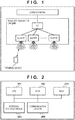
- FIG. 1 illustrates an example of a configuration of a radio communication system according to the present embodiment.
- the radio communication system according to the present embodiment is, for example, a mobile radio communication system of the fifth generation (5G) and includes a base station device (NR gNB) and a terminal device.
- a radio connection is established between the base station device and the terminal device and a radio signal is transmitted and received therebetween.
- the base station device is connected to a core network by, for example, a wire (in some cases, a line that includes a radio section) and is connected to other base station devices (not illustrated) via the core network.
- the core network is connected to an external network such as the Internet via, for example, a gateway, and the base station device can be connected to the external network via the core network.
- the base station device of the present embodiment includes, as internal units, a first part that controls lower layers in communication and a second part that controls upper layers.
- the first part is denoted with DU (distributed unit)/TRP (transmission receiver point) and the second part is denoted with CU (central unit).
- the first part is referred to as a DU and the second part is referred to as a CU.
- the DU of the present embodiment is configured to control at least a physical (PHY) layer and not to control at least a radio resource control (RRC) layer and layers higher than the RRC layer.
- the CU is configured to control layers that are higher than the DU and that include the RRC layer.
- a single DU may be connected to the CU, a plurality of DUs can be connected to the CU as illustrated in FIG. 1 .
- a line that connects the CU and the DU is called a fronthaul line.
- the CU and the DU may be directly connected as illustrated in FIG. 1 , or a switch (not illustrated) that is connected to a plurality of DUs may be connected to the CU and communication between the CU and each DU may be performed based on control of the switch. When a switch is used, communication between DUs can be performed without involving the CU.
- the DU is capable of forming a plurality of beams through beamforming.
- the number of beams that can be formed by the base station device increases, and therefore a large number of users can be accommodated and a total throughput of the system as a whole can be increased.
- the state of a radio wave may drastically deteriorate as a result of, for example, movement of the terminal device, and a radio link failure (RLF) may occur.
- RLF radio link failure
- the terminal device upon an RLF occurring in the radio link established in the high frequency band, the terminal device according to the present embodiment attempts to reestablish a radio link in the high frequency band rather than immediately attempting to establish a radio link in the low frequency band. Then, for example, after a predetermined period has elapsed, the terminal device attempts to establish a radio link in the low frequency band.
- the terminal device maintains the connection in the high frequency band as long as possible, and when the connection cannot be maintained, attempts to establish a connection in the low frequency band. Therefore, it is possible to maintain the connection while improving the throughput.
- the base station device notifies the terminal device of information regarding a period in which the terminal device is to attempt to reestablish a radio link in the high frequency band in the event of occurrence of an RLF in the radio link that is established in the high frequency band by the terminal device.
- the information to be notified here is, for example, information that specifies a timer value.
- the terminal device attempts to establish a radio link in the low frequency band when a period of time from the occurrence of the RLF reaches the timer value without succeeding in the attempt to reestablish a radio link in the high frequency band.
- the information to be notified may be information that specifies the number of attempts to reestablish a radio link in the high frequency band.
- the terminal device attempts to establish a radio link in the low frequency band when the terminal device does not succeed in reestablishing a radio link in the high frequency band despite the terminal device having made the specified number of attempts for the reestablishment. That is, the above-described predetermined period is a period that is determined by either the timer value or the number of attempts for the reestablishment notified by the base station device.
- the predetermined period (the timer value or the number of attempts) can be determined based on a property of a beam that is formed by the base station device to which the terminal device is connected by establishing the radio link in the high frequency band.
- the predetermined period can be determined such that, for example, the predetermined period is long when the width of the beam is wide, and the predetermined period is short when the width of the beam is narrow.
- the gain is ideally constant regardless of direction and a place that is far from the base station device is not included in the coverage. Accordingly, the terminal device connected with the beam is considered to be located at a position that is not far from the base station device.
- Such a terminal device located at a position not far from the base station device is considered to be highly likely to succeed in reestablishing a radio link when the terminal device attempts the reestablishment. Therefore, by setting a long period for attempting the reestablishment, it is possible to increase the probability that the terminal device can continue communication in the high frequency band by reestablishing a radio link in the high frequency band.
- the antenna gain is high in a specific direction and even a position that is far from the base station device can be included in the coverage.
- the terminal device may be located at a position far from the base station device and even when the terminal device attempts to reestablish a radio link, the probability that the terminal device will not succeed in the reestablishment may be high. Therefore, by setting a short period for attempting the reestablishment, it is possible to cause the terminal device to attempt to establish a connection in the low frequency band when the terminal device cannot reestablish a radio link in the high frequency band.
- the predetermined period may be determined such that, for example, the predetermined period is short when the width of the beam is wide, and the predetermined period is long when the width of the beam is narrow. That is, when the terminal device is connected with a beam that has a wide width, the terminal device is considered to be located at a position not far from the base station device as described above, and in such a case, it is expected that the terminal device will succeed in reestablishing a radio link in a short period of time.
- the terminal device when the terminal device is connected with a beam that has a wide width, the terminal device may be located at a position far from the base station device as described above, and therefore it may take a long time for the terminal device to succeed in reestablishing a radio link by entering the range of a beam. Therefore, by setting the predetermined period as described above, it is possible to increase the probability that a radio link will be reestablished in the high frequency band.
- Whether the width of the beam is wide or narrow can be determined based on, for example, a 3dB beam width that is determined by a difference between a direction in which a peak value of the antenna gain is obtained and a direction in which the antenna gain is half of the peak value. That is, when the 3dB beam width is narrower than a predetermined width, the predetermined period is set as the above-described case where the width of the beam is narrow, and when the 3dB beam width is wider than the predetermined width, the predetermined period is set as the above-described case where the width of the beam is wide. Note that the predetermined period may be determined stepwise according to the 3dB beam width.
- the terminal device can make notification of the occurrence of the RLF in the radio link in the high frequency band.
- the base station device of the low frequency band can request the base station device of the high frequency band to transfer data that is to be transmitted to the terminal device, based on the notification.
- the base station device of the low frequency band can acquire the data, which was to be transmitted by the base station device of the high frequency band, and transmit the data to the terminal device.
- a relationship between the high frequency band and the low frequency band has been described, this relationship should not be taken as a limitation. That is, the relationship between the high frequency band and the low frequency band may be opposite to that described above. Therefore, in the following description, a frequency band that corresponds to the above-described high frequency band will be referred to as a first frequency band, and a frequency band that corresponds to the above-described low frequency band will be described as a second frequency band, regardless of the frequency.
- the following describes configurations of the base station device and the terminal device that perform processing as described above and the flow of the processing.
- FIG. 2 illustrates an example of hardware configurations of the base station device and the terminal device.
- the base station device and the terminal device have the hardware configuration as illustrated in FIG. 2 , and includes, for example, a CPU 201, a ROM 202, a RAM 203, an external storage device 204, and a communication circuit 205.
- the CPU 201 executes programs that realize functions of the base station device and the terminal device as described above, the programs being stored in, for example, any of the ROM 202, the RAM 203, and the external storage device 204.
- the base station device and the terminal device communicate with another device through the communication circuit 205 that is controlled by the CPU 201, for example.
- the communication circuit 205 of the base station device can communicate with another base station device via a wired circuit, for example.
- the communication circuit 205 of the base station device can also perform radio communication with the terminal device by forming one or more (a plurality of) beams.
- the communication circuit 205 of the terminal device is configured such that it can connect with at least one of the beams formed by the communication circuit 205 of the base station device, and can perform radio communication with the base station device by using the beam.
- each of the base station device and the terminal device may include a plurality of communication circuits.
- the base station device includes a first communication circuit for communication with the core network and a second communication circuit for radio communication with the terminal device.
- the terminal device may include, for example, a first communication circuit in accordance with radio communication standards of the fourth or earlier generation and a second communication circuit in accordance with radio communication standards of the fifth generation.
- the terminal device may include, for example, a radio communication circuit in accordance with standards of a network such as a wireless LAN other than a cellular network, and may further include, for example, a wired communication circuit that is used for a wired connection such as a USB connection.
- the base station device and the terminal device may include dedicated hardware that performs respective functions, or some functions may be performed by hardware and other functions may be performed by a computer that executes programs. Alternatively, all functions may be performed by the computer and programs.
- the base station device includes, for example, a radio communication unit 301, a link reestablishment period determination unit 302, a transmission data holding unit 303, and a wired communication unit 304.
- a radio communication unit 301 for example, a radio communication unit 301, a link reestablishment period determination unit 302, a transmission data holding unit 303, and a wired communication unit 304.
- the base station device can have other functions of a general base station device, those functions are not illustrated in the drawings for simplification of the description.
- the radio communication unit 301 is capable of forming one or more beams in at least either the first frequency band or the second frequency band, or in another frequency band by, for example, controlling a non-illustrated antenna, and communicates with the terminal device by using at least one of the beams.
- the radio communication unit 301 generates a baseband signal from, for example, to-be-transmitted data that is held by the transmission data holding unit 303 or information that is generated by the link reestablishment period determination unit 302.
- the radio communication unit 301 is capable of converting the baseband signal to a signal of a radio frequency and outputting the signal as a radio signal from the antenna.
- the radio communication unit 301 is capable of converting a radio signal that is received by the antenna to a baseband signal and obtaining information from the baseband signal.
- the link reestablishment period determination unit 302 determines a period in which the terminal device is to attempt to establish a radio link in the first frequency band in the event of occurrence of a radio link failure (RLF) in a radio link that is established in the first frequency band by the terminal device, as described above.
- RLF radio link failure
- the "period" referred to herein may be expressed by a timer value or the number of attempts to reestablish a radio link as described above, or expressed according to any other standard. That is, any indicator that sets a specific period for the attempt to reestablish a radio link is determined as the "period" referred to herein.
- the link reestablishment period determination unit 302 may vary this period, for example, according to properties such as the width of the beam with which the terminal device is connected, as described above.
- the link reestablishment period determination unit 302 may determine different periods for respective terminal devices.
- the link reestablishment period determination unit 302 can determine the period according to performance of the terminal device regarding radio communication.
- the link reestablishment period determination unit 302 can determine the period such that the period is long when the probability that the reestablishment of a radio link will succeed is increased due to the performance of the terminal device, and the period is short when the probability is not increased due to the performance of the terminal device.
- the period may be determined in a way opposite to the above.
- the link reestablishment period determination unit 302 may determine the period each time based on, for example, the number of terminal devices that are connected to the base station device in the first frequency band or the number of terminal devices that are located in the surrounding region. For example, when a large number of terminal devices are connected to the base station device in the first frequency band, it is highly likely that another terminal device has already established a radio link for communication by using a beam that is a target of the attempt to reestablish a radio link, and therefore a short period may be set to urge the terminal device to transition to the second frequency band.
- the link reestablishment period determination unit 302 can determine the above-described period by using various measures. Note that when a uniform period that does not change is applied to all terminal devices, the link reestablishment period determination unit 302 may merely notify the terminal device of that period without determining the period.
- the link reestablishment period determination unit 302 notifies the terminal device of information regarding the determined period through the radio communication unit 301.
- the link reestablishment period determination unit 302 can make this notification, for example, when a radio resource control (RRC) connection with the terminal device is established in the first frequency band.
- RRC radio resource control
- the link reestablishment period determination unit 302 may make the notification by using a broadcast signal, for example, irrespective of before or after establishment of the RRC connection in the first or second frequency band.
- the broadcast signal is, for example, a Master Information Block (MIB) or a System Information Block (SIB).
- the transmission data holding unit 303 holds data that is to be transmitted to the terminal device.
- the wired communication unit 304 performs wired communication with a node in the core network or another base station device.
- the transmission data holding unit 303 holds to-be-transmitted data by, for example, acquiring the data from the core network through the wired communication unit 304, and the radio communication unit 301 transmits the held data to the terminal device.
- the wired communication unit 304 transfers the data held by the transmission data holding unit 303 to the other base station device.
- the radio communication unit 301 may be capable of performing radio communication in both the first frequency band and the second frequency band, and the terminal device may establish a radio link with the radio communication unit 301 in the second frequency band after the occurrence of RLF in the first frequency band. In such a case, there is no need to transfer the to-be-transmitted data, and therefore the radio communication unit 301 transmits the data held by the transmission data holding unit 303 in the second frequency band after establishment of the radio link in the second frequency band.
- the terminal device includes a radio communication unit 401, a link establishment control unit 402, and an RLF notifying unit 403.
- the terminal device can include various other functional units of a general communication terminal or a general electronic equipment that has a communication function, those functions are not illustrated in the drawings for simplification of the description.
- the radio communication unit 401 is configured such that it can connect with at least one of a plurality of beams that are formed by one or more base station devices by controlling a non-illustrated antenna.
- the radio communication unit 401 is capable of generating a baseband signal from, for example, to-be-transmitted data or information that is generated by the RLF notifying unit 403, converting the baseband signal to a signal of a radio frequency, and outputting the signal as a radio signal from the antenna.
- the radio communication unit 401 is capable of converting a radio signal that is received by the antenna to a baseband signal, and obtaining information from the baseband signal.
- the link establishment control unit 402 establishes a radio link with the base station device in the first frequency band or the second frequency band by controlling the radio communication unit 401.
- the link establishment control unit 402 attempts to establish a radio link based on the information regarding the period. That is, upon the occurrence of a radio link failure (RLF) in a radio link that is established in the first frequency band by the terminal device, the link establishment control unit 402 attempts to reestablish a radio link in the first frequency band during the period.
- RLF radio link failure
- the link establishment control unit 402 When the period corresponding to the received information has elapsed without succeeding in the reestablishment of a radio link in the first frequency band, the link establishment control unit 402 attempts to establish a radio link in the second frequency band. After establishing a radio link in the second frequency band, the link establishment control unit 402 notifies the RLF notifying unit 403 of the establishment of the radio link in the second frequency band.
- the RLF notifying unit 403 controls the radio communication unit 401 to give notification of the occurrence of the RLF in the first frequency band to a base station device that is connected with the radio link in the second frequency band.
- the base station device connected with the radio link in the second frequency band requests the base station device that was connected with the radio link in the first frequency band to transfer to-be-transmitted data that is to be transmitted to the terminal device. Note that the above does not apply when the base station device connected with the radio link in the second frequency band is the same as the base station device connected with the radio link in the first frequency band.
- the base station device can transmit the data to the terminal device by acquiring the data from the same transmission data holding unit 303, and therefore there is no need to transfer the data.
- FIG. 5 is a sequence diagram illustrating an example of the flow of processing executed by the radio communication system according to the present embodiment.
- the following describes processing in a radio communication system that includes two base station devices (base station devices A and B) that provide a radio communication service in the first frequency band, a base station device (base station device C) that provides a radio communication service in the second frequency band, and a terminal device.
- base station devices A and B that provide a radio communication service in the first frequency band
- base station device C base station device that provides a radio communication service in the second frequency band
- a terminal device merely an example, and the two base station devices that provide the radio communication service in the first frequency band may be replaced with, for example, a base station device that is capable of providing two different beams.
- the terminal device upon the occurrence of an RLF in a radio link that is established in the first frequency band, the terminal device attempts to reestablish a radio link in the first frequency band by using a beam that is different from a beam used for the radio link in which the RLF occurred.
- the terminal device may attempt to reestablish a radio link in the first frequency band by using the same beam as that used for the radio link in which the RLF occurred.
- the base station device that provides the radio communication service in the first frequency band and the base station device that provides the radio communication service in the second frequency band may be constituted by a single device.
- the first frequency band is a high frequency band and the second frequency band is a low frequency band.
- the first frequency band and the second frequency band may belong to the same frequency band, or the second frequency band may be higher in frequency than the first frequency band.
- the base station devices A to C determine a period in which the terminal device is to attempt to reestablish a radio link in the first frequency band in the event of occurrence of a radio link failure (RLF) in a radio link that is established in the first frequency band at the terminal device (S501). Note that this period may be determined in advance, in which case, processing in step S501 need not be executed. Also, it is not required that all of the base station devices determine the period as above, and this processing may be executed by only some of the base station devices. Thereafter, the base station devices A to C transmit information regarding the determined period by using broadcast signals (MIB or SIB) (S502).
- MIB or SIB broadcast signals
- the terminal device receives any of the broadcast signals, and based on the notified information regarding the period, sets a period for attempting reestablishment of a radio link in the event of the occurrence of an RLF after establishment of a radio link in the first frequency band. It is assumed that thereafter the terminal device establishes a radio link with the base station device A in the first frequency band (S503). Note that, although in this example of processing, the terminal device establishes the radio link after acquiring the information regarding the period for attempting reestablishment of a radio link, the terminal device may acquire this information by receiving the broadcast signal after establishing the radio link.
- the terminal device may determine that it has failed in reestablishing a radio link in the first frequency band when, for example, the terminal device does not succeed in reestablishing a radio link despite the terminal device attempting to reestablish a radio link the number of times corresponding to the reported period.
- the terminal device Upon determining the failure of the reestablishment of a radio link in the first frequency band, the terminal device attempts to establish a radio link with the base station device C that provides the radio communication service in the second frequency band (S507).
- the terminal device requests a connection, to the base station device C, by using a random access channel, for example.
- the base station device C then transmits, for example, an RRC Connection Reconfiguration message that includes setting information for establishing a radio link in the second frequency band.
- an RRC Connection Reconfiguration message that includes setting information for establishing a radio link in the second frequency band.
- a radio link is established between the base station device C and the terminal device in the second frequency band.
- the terminal device notifies the base station device C that an RLF occurred in the radio link established in the first frequency band (S508).
- the terminal device may provide this notification by, for example, using the above-described random access channel, or transmitting an individual message after establishment of the radio link.
- This notification may include, for example, information that requests the base station device C to transmit user data that was to be transmitted to the terminal device by using the radio link established in the first frequency band.
- the base station device C Upon receiving the notification of the occurrence of the RLF in the radio link in the first frequency band from the terminal device, the base station device C requests the base station device A, which was connected with the radio link in which the RLF occurred, to transfer the user data to be transmitted to the terminal device (S509).
- the base station device C receives, from the base station device A, the user data to be transmitted to the terminal device (S510) and transmits the received user data to the terminal device (S511).
- FIG. 6 illustrates processing in such a case.
- the terminal device establishes a radio link with the base station device A in the first frequency band (S601).
- the terminal device establishes the radio link with the base station device A in the first frequency band when, for example, there arises a need for the terminal device to use the radio communication service while the terminal device is located within the coverage of a beam that is formed by the base station device A in the first frequency band.
- the base station device A determines a period in which the terminal device is to attempt to reestablish a radio link in the first frequency band in the event of occurrence of a radio link failure (RLF) in the radio link established by the terminal device in the first frequency band (S602). Note that this period may be determined in advance, in which case, processing in step S602 need not be executed.
- RLF radio link failure
- the other base station devices (base station devices B and C) that are not connected to the terminal device need not determine this period. Thereafter, the base station device A notifies the terminal device of information regarding the period in which the terminal device is to attempt to reestablish a radio link in the first frequency band in the event of the occurrence of an RLF in the radio link established in the first frequency band (S603).
- the subsequent processing is similar to that illustrated in FIG. 5 , and therefore illustrated by using similar reference numerals and a description thereof is omitted.
- the base station device notifies the terminal device of information regarding a period in which the terminal device is to attempt to reestablish a radio link in the first frequency band, rather than immediately switching to the second frequency band, when an RLF occurs in a radio link established in the first frequency band. Therefore, it is possible to increase the probability that the terminal device can maintain and reestablish a radio link in the first frequency band when, for example, highly efficient/broadband/high-speed communication can be performed in the first frequency band, and the throughput of the radio communication system as a whole can be improved. Further, the terminal device attempts to establish a radio link in the second frequency band when a radio link cannot be reestablished in the first frequency band, and therefore communication can be maintained. Thus, according to the present embodiment, it is possible to maintain the connection between the terminal device and the base station device while improving the throughput of the radio communication system.
Landscapes
- Engineering & Computer Science (AREA)
- Computer Networks & Wireless Communication (AREA)
- Signal Processing (AREA)
- Mobile Radio Communication Systems (AREA)
Applications Claiming Priority (2)
| Application Number | Priority Date | Filing Date | Title |
|---|---|---|---|
| JP2016189442A JP6656130B2 (ja) | 2016-09-28 | 2016-09-28 | 基地局装置、端末装置、制御方法、及びプログラム |
| PCT/JP2017/022778 WO2018061347A1 (ja) | 2016-09-28 | 2017-06-21 | 基地局装置、端末装置、制御方法、及びプログラム |
Publications (2)
| Publication Number | Publication Date |
|---|---|
| EP3522671A1 true EP3522671A1 (de) | 2019-08-07 |
| EP3522671A4 EP3522671A4 (de) | 2019-08-14 |
Family
ID=61762588
Family Applications (1)
| Application Number | Title | Priority Date | Filing Date |
|---|---|---|---|
| EP17855306.1A Withdrawn EP3522671A4 (de) | 2016-09-28 | 2017-06-21 | Basisstationsvorrichtung, endgerätevorrichtung, steuerungsverfahren und programm |
Country Status (5)
| Country | Link |
|---|---|
| US (1) | US20190208564A1 (de) |
| EP (1) | EP3522671A4 (de) |
| JP (1) | JP6656130B2 (de) |
| CN (1) | CN109691163A (de) |
| WO (1) | WO2018061347A1 (de) |
Families Citing this family (3)
| Publication number | Priority date | Publication date | Assignee | Title |
|---|---|---|---|---|
| JP6692728B2 (ja) | 2016-09-28 | 2020-05-13 | Kddi株式会社 | 端末装置、ネットワーク装置、制御方法、及びプログラム |
| IT201900024000A1 (it) * | 2019-12-13 | 2021-06-13 | Telecom Italia Spa | Metodo e sistema per sfruttare connessioni ad onde millimetriche |
| FI129680B (en) * | 2021-03-02 | 2022-06-30 | Elisa Oyj | Procedure for managing call capacity in a mobile network |
Family Cites Families (8)
| Publication number | Priority date | Publication date | Assignee | Title |
|---|---|---|---|---|
| US20080074994A1 (en) * | 2006-09-21 | 2008-03-27 | Innovative Sonic Limited | Method for detecting radio link failure in wireless communications system and related apparatus |
| WO2009096883A1 (en) * | 2008-01-18 | 2009-08-06 | Telefonaktiebolaget L M Ericsson (Publ) | Method and apparatus for radio link failure recovery in a telecommunication system |
| US8929894B2 (en) * | 2009-01-06 | 2015-01-06 | Qualcomm Incorporated | Handover failure messaging schemes |
| US8406160B2 (en) * | 2010-05-21 | 2013-03-26 | Qualcomm Incorporated | Time-sliced search of radio access technologies during connected-mode radio link failure |
| PL3503665T3 (pl) * | 2012-11-13 | 2021-08-02 | Telefonaktiebolaget Lm Ericsson (Publ) | Sposób modyfikacji wartości parametrów dla rozszerzania zakresu dalekiego zasięgu odpowiadającego urządzenia bezprzewodowego i stacji bazowej |
| US9888419B2 (en) * | 2014-10-15 | 2018-02-06 | Lg Electronics Inc. | Methods and devices for performing fast fallback in wireless access system supporting millimeter waves (mmWave) |
| KR102363547B1 (ko) * | 2014-11-26 | 2022-02-17 | 삼성전자주식회사 | 빔포밍을 이용한 통신 방법 및 장치 |
| JPWO2016147602A1 (ja) * | 2015-03-18 | 2018-01-11 | 日本電気株式会社 | 移動通信端末、通信制御装置、通信制御方法及びプログラム |
-
2016
- 2016-09-28 JP JP2016189442A patent/JP6656130B2/ja active Active
-
2017
- 2017-06-21 EP EP17855306.1A patent/EP3522671A4/de not_active Withdrawn
- 2017-06-21 CN CN201780055001.8A patent/CN109691163A/zh active Pending
- 2017-06-21 WO PCT/JP2017/022778 patent/WO2018061347A1/ja not_active Ceased
-
2019
- 2019-03-07 US US16/295,333 patent/US20190208564A1/en not_active Abandoned
Also Published As
| Publication number | Publication date |
|---|---|
| JP2018056748A (ja) | 2018-04-05 |
| US20190208564A1 (en) | 2019-07-04 |
| CN109691163A (zh) | 2019-04-26 |
| EP3522671A4 (de) | 2019-08-14 |
| WO2018061347A1 (ja) | 2018-04-05 |
| JP6656130B2 (ja) | 2020-03-04 |
Similar Documents
| Publication | Publication Date | Title |
|---|---|---|
| US12323822B2 (en) | Communication system | |
| EP3827619B1 (de) | Übertragung von netzwerk-slicing-beschränkungen in drahtlosen netzwerken | |
| US10887740B2 (en) | Message sending method and apparatus | |
| US12127062B2 (en) | Timing advance for rach-less backhaul handover | |
| JP2022116196A (ja) | 無線デバイスのための分散型モビリティ | |
| US11622406B2 (en) | Dual connectivity method and access network device | |
| US20190208448A1 (en) | Control device, terminal device, control method, and computer-readable storage medium | |
| CN112534869B (zh) | 蜂窝无线局域网(wlan)网络接口 | |
| CN110506437B (zh) | 一种信道资源分配方法和装置 | |
| US20230308971A1 (en) | Methods and apparatus for supporting switching of traffic corresponding to a communication session between two non-3gpp access paths | |
| JP2021517751A (ja) | セカンダリセルを構成するための方法、装置及びコンピュータ記憶媒体 | |
| CN115297548B (zh) | 用于进行中继通信的蜂窝通信网络的基站装置、终端装置以及它们的控制方法 | |
| US12200470B2 (en) | Methods and apparatus for supporting efficient multi-universal subscriber identify module (musim) user equipment (ue) operation using a multi-path proxy | |
| WO2022027232A1 (zh) | 无线通信方法和设备 | |
| US20190208564A1 (en) | Base station device, terminal device, control method, and computer-readable storage medium | |
| KR20170019153A (ko) | 무선 통신 시스템에서 데이터를 송수신하는 장치 및 방법 | |
| US12219379B2 (en) | Relaxed inter-frequency measurements | |
| CN115668890B (zh) | 通信网络中的应用功能节点、接入和移动性管理功能节点、系统和方法 | |
| JP6850915B2 (ja) | 基地局装置、端末装置、制御方法、及びプログラム | |
| US12068833B2 (en) | Beam sweeping for SSB polarization switching | |
| CN112449384B (zh) | 数据处理方法、装置和系统 | |
| WO2023274127A1 (zh) | 路由选择、重路由及路由配置方法、iab节点和cu节点 | |
| CN116133111B (zh) | 一种切片处理方法及装置、通信设备 | |
| US20250310808A1 (en) | Methods, communications devices and infrastructure equipment | |
| US11051221B2 (en) | Network access method and device |
Legal Events
| Date | Code | Title | Description |
|---|---|---|---|
| STAA | Information on the status of an ep patent application or granted ep patent |
Free format text: STATUS: THE INTERNATIONAL PUBLICATION HAS BEEN MADE |
|
| PUAI | Public reference made under article 153(3) epc to a published international application that has entered the european phase |
Free format text: ORIGINAL CODE: 0009012 |
|
| STAA | Information on the status of an ep patent application or granted ep patent |
Free format text: STATUS: REQUEST FOR EXAMINATION WAS MADE |
|
| 17P | Request for examination filed |
Effective date: 20190307 |
|
| AK | Designated contracting states |
Kind code of ref document: A1 Designated state(s): AL AT BE BG CH CY CZ DE DK EE ES FI FR GB GR HR HU IE IS IT LI LT LU LV MC MK MT NL NO PL PT RO RS SE SI SK SM TR |
|
| AX | Request for extension of the european patent |
Extension state: BA ME |
|
| A4 | Supplementary search report drawn up and despatched |
Effective date: 20190717 |
|
| RIC1 | Information provided on ipc code assigned before grant |
Ipc: H04W 76/20 20180101AFI20190711BHEP |
|
| DAV | Request for validation of the european patent (deleted) | ||
| DAX | Request for extension of the european patent (deleted) | ||
| STAA | Information on the status of an ep patent application or granted ep patent |
Free format text: STATUS: EXAMINATION IS IN PROGRESS |
|
| 17Q | First examination report despatched |
Effective date: 20201218 |
|
| STAA | Information on the status of an ep patent application or granted ep patent |
Free format text: STATUS: THE APPLICATION IS DEEMED TO BE WITHDRAWN |
|
| 18D | Application deemed to be withdrawn |
Effective date: 20220915 |