EP3522802B1 - Système de fixation osseuse à l'aide d'une plaque chevauchée par un élément de retenue - Google Patents
Système de fixation osseuse à l'aide d'une plaque chevauchée par un élément de retenue Download PDFInfo
- Publication number
- EP3522802B1 EP3522802B1 EP17859229.1A EP17859229A EP3522802B1 EP 3522802 B1 EP3522802 B1 EP 3522802B1 EP 17859229 A EP17859229 A EP 17859229A EP 3522802 B1 EP3522802 B1 EP 3522802B1
- Authority
- EP
- European Patent Office
- Prior art keywords
- plate
- retainer
- bone
- aperture
- line
- Prior art date
- Legal status (The legal status is an assumption and is not a legal conclusion. Google has not performed a legal analysis and makes no representation as to the accuracy of the status listed.)
- Active
Links
Images




Classifications
-
- A—HUMAN NECESSITIES
- A61—MEDICAL OR VETERINARY SCIENCE; HYGIENE
- A61B—DIAGNOSIS; SURGERY; IDENTIFICATION
- A61B17/00—Surgical instruments, devices or methods
- A61B17/56—Surgical instruments or methods for treatment of bones or joints; Devices specially adapted therefor
- A61B17/58—Surgical instruments or methods for treatment of bones or joints; Devices specially adapted therefor for osteosynthesis, e.g. bone plates, screws or setting implements
- A61B17/68—Internal fixation devices, including fasteners and spinal fixators, even if a part thereof projects from the skin
- A61B17/80—Cortical plates, i.e. bone plates; Instruments for holding or positioning cortical plates, or for compressing bones attached to cortical plates
-
- A—HUMAN NECESSITIES
- A61—MEDICAL OR VETERINARY SCIENCE; HYGIENE
- A61B—DIAGNOSIS; SURGERY; IDENTIFICATION
- A61B17/00—Surgical instruments, devices or methods
- A61B17/56—Surgical instruments or methods for treatment of bones or joints; Devices specially adapted therefor
- A61B17/58—Surgical instruments or methods for treatment of bones or joints; Devices specially adapted therefor for osteosynthesis, e.g. bone plates, screws or setting implements
- A61B17/68—Internal fixation devices, including fasteners and spinal fixators, even if a part thereof projects from the skin
- A61B17/80—Cortical plates, i.e. bone plates; Instruments for holding or positioning cortical plates, or for compressing bones attached to cortical plates
- A61B17/8052—Cortical plates, i.e. bone plates; Instruments for holding or positioning cortical plates, or for compressing bones attached to cortical plates immobilised relative to screws by interlocking form of the heads and plate holes, e.g. conical or threaded
- A61B17/8057—Cortical plates, i.e. bone plates; Instruments for holding or positioning cortical plates, or for compressing bones attached to cortical plates immobilised relative to screws by interlocking form of the heads and plate holes, e.g. conical or threaded the interlocking form comprising a thread
-
- A—HUMAN NECESSITIES
- A61—MEDICAL OR VETERINARY SCIENCE; HYGIENE
- A61B—DIAGNOSIS; SURGERY; IDENTIFICATION
- A61B17/00—Surgical instruments, devices or methods
- A61B17/56—Surgical instruments or methods for treatment of bones or joints; Devices specially adapted therefor
- A61B17/58—Surgical instruments or methods for treatment of bones or joints; Devices specially adapted therefor for osteosynthesis, e.g. bone plates, screws or setting implements
- A61B17/68—Internal fixation devices, including fasteners and spinal fixators, even if a part thereof projects from the skin
- A61B17/80—Cortical plates, i.e. bone plates; Instruments for holding or positioning cortical plates, or for compressing bones attached to cortical plates
- A61B17/8033—Cortical plates, i.e. bone plates; Instruments for holding or positioning cortical plates, or for compressing bones attached to cortical plates having indirect contact with screw heads, or having contact with screw heads maintained with the aid of additional components, e.g. nuts, wedges or head covers
-
- A—HUMAN NECESSITIES
- A61—MEDICAL OR VETERINARY SCIENCE; HYGIENE
- A61B—DIAGNOSIS; SURGERY; IDENTIFICATION
- A61B17/00—Surgical instruments, devices or methods
- A61B17/56—Surgical instruments or methods for treatment of bones or joints; Devices specially adapted therefor
- A61B17/58—Surgical instruments or methods for treatment of bones or joints; Devices specially adapted therefor for osteosynthesis, e.g. bone plates, screws or setting implements
- A61B17/68—Internal fixation devices, including fasteners and spinal fixators, even if a part thereof projects from the skin
- A61B17/84—Fasteners therefor or fasteners being internal fixation devices
- A61B17/842—Flexible wires, bands or straps
-
- A—HUMAN NECESSITIES
- A61—MEDICAL OR VETERINARY SCIENCE; HYGIENE
- A61B—DIAGNOSIS; SURGERY; IDENTIFICATION
- A61B17/00—Surgical instruments, devices or methods
- A61B17/56—Surgical instruments or methods for treatment of bones or joints; Devices specially adapted therefor
- A61B17/58—Surgical instruments or methods for treatment of bones or joints; Devices specially adapted therefor for osteosynthesis, e.g. bone plates, screws or setting implements
- A61B17/68—Internal fixation devices, including fasteners and spinal fixators, even if a part thereof projects from the skin
- A61B17/82—Internal fixation devices, including fasteners and spinal fixators, even if a part thereof projects from the skin for bone cerclage
-
- A—HUMAN NECESSITIES
- A61—MEDICAL OR VETERINARY SCIENCE; HYGIENE
- A61B—DIAGNOSIS; SURGERY; IDENTIFICATION
- A61B17/00—Surgical instruments, devices or methods
- A61B2017/00004—(bio)absorbable, (bio)resorbable or resorptive
-
- A—HUMAN NECESSITIES
- A61—MEDICAL OR VETERINARY SCIENCE; HYGIENE
- A61B—DIAGNOSIS; SURGERY; IDENTIFICATION
- A61B17/00—Surgical instruments, devices or methods
- A61B17/56—Surgical instruments or methods for treatment of bones or joints; Devices specially adapted therefor
- A61B2017/564—Methods for bone or joint treatment
Definitions
- a fractured long bone can be fixed with an elongated bone plate secured to the bone with fasteners, such as bone screws, while the bone plate spans one or more fractures.
- the bone screws may be placed into the bone from a series of apertures arranged along the bone plate.
- the screws typically are long enough to extend across the bone's medullary canal, for bicortical engagement with bone.
- Achieving bicortical engagement of screws can be problematic when fixing a bone having a peri-prosthetic fracture.
- the fracture line overlaps a previously-installed, underlying prosthesis.
- the prosthesis has an intramedullary stem for anchorage, and a head to replace an articulating end of the bone.
- the stem occupies a section of the medullary canal, thus obstructing a standard bicortical trajectory of bone screws.
- Screw trajectories can be moved outside of the bone's medullary canal through the use of an attachment plate mounted over a fixation plate, as disclosed in U.S. Patent Application Publication No. 2010/0262194 A1 .
- US 2014243907 discloses a system including a compression plate and a cerclage cable for encircling the bone and securing the compression plate to the bone.
- the cable has a ball or other structure functioning as a stop at one end, and a free end.
- the attachment plate is secured separately to the fixation plate and bone, which limits the number of positions at which the attachment plate can be installed. Variations in bone size and geometry can make securing the attachment plate to bone unreliable, thereby reducing the number of positions even further.
- the present invention relates to a system for fixing bone as claimed hereafter.
- Preferred embodiments of the invention are set forth in the dependent claims. Associated methods are also described herein to aid understanding of the invention, but these do not form part of the claimed invention.
- the plate is an elongated plate configured to be disposed longitudinally on a bone.
- the retainer has a body interconnecting a pair of mounting regions.
- the body defines a recess, and each mounting region defines a first aperture and a second aperture.
- the retainer is configured to be mated with the plate to position a section of the plate in the recess such that the retainer straddles the plate.
- the first apertures are configured to define through-axes that are tangential to the bone, to enable use with a line including wire and/or cable
- each second aperture are configured to define a through-axis that extends through opposite sides of the bone while avoiding a medullary canal thereof, to enable use with a threaded fastener.
- the plate may be an elongated plate configured to be disposed longitudinally on a bone.
- the retainer may have a body interconnecting a pair of mounting regions.
- the body may define a recess, and each mounting region may define a first aperture and a second aperture.
- the retainer may be configured to be mated with the plate to position a section of the plate in the recess such that the retainer straddles the plate.
- the first apertures may be configured to define through-axes that are tangential to the bone, to enable use with a line including wire and/or cable, and each second aperture may be configured to define a through-axis that extends through opposite sides of the bone while avoiding a medullary canal thereof, to enable use with a threaded fastener.
- the system may comprise a plate configured to be disposed on a bone, and a retainer.
- the retainer may have a first mounting region opposite a second mounting region.
- the retainer may be configured to straddle the plate such that the first mounting region and the second mounting region project away from opposite lateral edges of the plate.
- Each of the first mounting region and the second mounting region may define an aperture.
- the system also may comprise a line and a sleeve.
- the line is a cable or wire.
- the line may be configured to extend from the aperture of the first mounting region to the aperture of the second mounting region, such that the retainer and the line collectively encircle a bone.
- the sleeve may be configured to be received on the line and crimped to lock the sleeve to the line.
- a bone having a peri-implant fracture can be challenging.
- the bone can be stabilized with a wider bone plate designed specifically for peri-prosthetic fractures.
- this bone plate cannot be customized readily for the needs of a given patient having a particular bone size and shape, fracture pattern, and implant.
- the bone alternatively can be fixed with a fixation plate and an attachment plate.
- the attachment plate fits over the fixation plate and is configured to be attached to bone with bone screws.
- the bone screws often do not provide sufficient anchorage or miss the bone completely.
- the surgeon has more options for attaching a bone plate to bone. Accordingly, the bone plate can be installed more efficiently and securely. Also or alternatively, the bone plate when attached to bone can have the stability of a wider plate but the footprint of a narrower plate.
- This section describes an exemplary bone fixation system 50 including a plate 52 and an encircling assembly 54 incorporating a plate-straddling retainer 56; see Figures 1-16 .
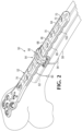
- Figures 1 and 2 show fixation system 50 attached to a distal portion of a femur 58 having at least one discontinuity, such as at least one fracture 60, with plate 52 spanning the discontinuity.
- the system may be utilized to stabilize any suitable portion of any suitable bone.
- the system may be attached to a bone having at least a portion of an implant 62 extending along a medullary canal thereof, and the implant, plate 52, encircling assembly 54, and/or retainer 56 may be located at mutually overlapping positions along the bone, such as overlapping positions in a shaft region of the bone (also see Section II).
- Plate 52 may have any suitable structure and orientation on bone.
- the plate may be elongated and oriented longitudinally on the bone, as shown.
- Plate 52 may have an inner surface 64 (also called a bone-facing surface or bottom surface) opposite an outer surface 66 (also called a top surface).
- the plate also may have a pair of lateral edges 68 (also called lateral sides) located intermediate surfaces 64, 66 and extending between opposite ends of the plate.
- the plate may define a plurality of apertures 70 to receive fasteners, such as bone screws that attach the plate to bone.
- Each fastener may be a linear fastener, which may have one or more external threads to engage the plate or bone (or both).
- Each aperture 70 may extend through plate 52 from inner surface 64 to outer surface 66.
- Each of the fasteners placed into an aperture 70 independently may or may not lock to the wall of the aperture, such as via an internal thread 72 of the aperture.
- Each aperture independently may be circular or elongated transversely (e.g., orthogonally) to a through-axis of the aperture, among others.
- Other exemplary fasteners for engagement of plate 52 include pins, pegs, rivets, staples, wires, retainer 56, or the like. Any suitable number of apertures 70, such as only a subset of the apertures, may receive fasteners that connect plate 52 to bone.
- Fixation system 50 may include one or more retainers 56, each of which may be installed over plate 52 at the discretion of the surgeon. Each retainer 56 may be positioned at a selected position along a centerline 74 of plate 52 to couple the plate to bone at that position. (The centerline may be linear or curved.) The position may be selected from a continuous range of permitted axial positions at which the retainer can be installed.
- the retainer may be introduced where local attachment of the plate to the bone via fasteners placed into apertures 70 is not feasible, not effective, needs reinforcement, or the like.
- the retainer may be described as a supplemental plate or an attachment plate.
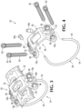
- Each retainer 56 may have a body 76 and a pair of mounting regions 78a, 78b interconnected by the body (see Figures 3 and 4 ).
- the mounting regions may be located opposite one another on opposite sides of body 76.
- the body may be contoured to be complementary to a section of the plate by defining a recess 80 (interchangeably called a receiving space) in the underside of the body.
- the recess allows the retainer to be mated with plate 52, such that body 76 receives a section of the plate and straddles the plate.
- body 76 may be located on/adjacent, and optionally in contact with, outer surface 66 and lateral edges 68 to cover a portion of each.
- the cross-sectional shape of plate 52 may be sufficiently uniform along at least a portion of its length to allow the retainer to be mated with the plate at each of a plurality of alternative longitudinal positions along the plate, and/or to allow the retainer, once mated, to slide longitudinally along the plate to a desired position. (An alternative longitudinal position of the retainer is shown in phantom outline in Figure 1 .) Mounting regions 78a, 78b of the mated retainer may be disposed respectively on opposite lateral sides of plate 52, and may project away from respective lateral edges 68 of plate 52, and/or in opposite circumferential directions on the bone.
- Retainer 56 may be secured to bone via mounting regions 78a, 78b to couple plate 52 to bone (see Figures 1-4 ).
- Each mounting region may be attached to bone via (a) at least one threaded fastener 82 (which be linear and/or threaded externally), (b) a spanning member 84 extending from one mounting region to the other mounting region such that the spanning member and the retainer cooperatively form encircling assembly 54 that encircles plate 52 and the bone, or (c) both.
- Each mounting region 78a, 78b may define one or more apertures to receive fastener(s) 82 and/or spanning member 84.
- the mounting region may define at least one aperture 86 to operatively receive threaded fastener(s) 82 (see Figure 4 ).
- Each aperture 86 may have an internal thread for threaded engagement with fastener 82.
- fastener 82 may have an externally-threaded trailing portion 88 that locks the fastener to aperture 86.
- the fastener may not lock to the aperture because the aperture lacks an internal thread and/or the fastener lacks a complementary external thread.
- the system may include a first set of fasteners that lock to apertures 86 via the internal thread thereof, and a second set of fasteners that do not lock to the apertures.
- the second set of fasteners allow the surgeon to choose the trajectories followed by the fasteners into the bone.
- fastener 82 may have an externally threaded shaft 90 to engage bone under the mounting region.
- the diameter of shaft 90 may be less than that of trailing portion 88.
- the mounting region also or alternatively may define an aperture 92 sized to receive and engage part of spanning member 84.
- the spanning member may include a line 94 and a pair of stop members 96a, 96b.
- the line may be a length of cable/wire or the like that is capable of following a circumferential path around the bone between mounting regions 78a, 78b.
- the line may be sufficiently flexible to conform generally to a convex contour of the bone.
- Each stop member may be any structure having a fixed or fixable position along the line, and sized to prevent passage, completely through aperture 92, of the stop member (and the attached line).
- One of the stop members may be pre-attached to the line during manufacture (e.g., by crimping, welding, press-fitting, or the like), or both stop members may be attached to the line intra-operatively, among others.
- the stop members may or may not have the same structure (e.g., may or may not be substantially identical to one another).
- at least one of the stop members may be a sleeve through which the line can extend.
- the sleeve may be deformable (i.e., crimpable) to lock (firmly attach) the sleeve to the line, such that the sleeve can no longer slide along the line.
- Figures 5-7 show retainer 56 mated with plate 52.
- a section of plate 52 is located in recess 80 of retainer 56.
- the retainer has a top portion 98 positioned over outer surface 66 of the plate, and has lateral portions 100 positioned adjacent lateral edges 68 of the plate.
- the retainer and plate may define complementary mating structures that slidably connect the retainer and plate to one another via a snap-fit connection upon mating (and before the retainer is attached to bone with fasteners 82 and/or spanning member 84).
- the mating structures may include a pair of longitudinal tracks 102 provided by plate 52 that resist removal of retainer 56, when the retainer is urged away from the plate normal to the outer surface of the plate, while guiding movement of the retainer along the plate, parallel to centerline 74 (see Figures 2 , 3 , and 6 ).
- tracks 102 are furrows defined by lateral edges 68 of plate 52, and retainer 56 defines complementary protrusions 104, such as ridges, on lateral portions 100 in recess 80.
- the tracks may be formed by protrusions, such as ridges, on plate 52, and complementary indentations may be defined in corresponding lateral wall portions of recess 80.
- the retainer (and/or the plate) may deform as the retainer is being mated with the plate, to allow the complementary mating structures to be placed into operative interaction. Accordingly, the retainer when first mated with the plate, may provide haptic and/or audible feedback to the surgeon when mating has been completed. The retainer also may need to be deformed to separate the complementary mating structures from one another, thereby permitting removal of the retainer from the plate. In some cases, a tool may be utilized to apply sufficient force for removal.
- Figures 5-7 illustrate how the retainer can be coupled to femur 58 (or another bone) using spanning member 84 ( Figure 6 ) and/or fasteners 82 ( Figure 7 ), while avoiding implant 62 in medullary canal 106 of the femur.
- Figures 6 and 7 compare through-axes 108 defined by apertures 92 used for spanning member 84, with through-axes 110 defined by apertures 86 for threaded fasteners 82.
- Axes 108 may be tangential with respect to the bone, to guide line 94 of spanning member 84 in a circumferential direction on the bone. This arrangement helps to prevent the line from getting kinked.
- tangential for an axis in relation to a bone means substantially following a tangent defined by the bone, such that the axis passes close to the surface of the bone, either missing the bone completely or only passing through the bone peripherally.
- axes 110 may be oriented relatively more radially with respect to the bone, and may pass through opposite sides of the bone, to guide fastener 82 into the bone, optionally while missing medullary canal 106 (and thus implant 62).
- axes 108, 110 also may be contrasted by their relationships to a radial plane 112 and a tangential plane 114 (see Figures 6 and 7 ).
- Radial plane 112 is centered between mounting regions 78a, 78b and oriented at least generally radially with respect to the bone.
- the radial plane is parallel to (and optionally contains) an extension axis 116 on which plate 52 extends through retainer 56, and may bisect the retainer.
- Tangential plane 114 is orthogonal to radial plane 112 and tangential to the bone.
- Through-axes 108 and 110 may intersect radial plane 112 on opposite sides of tangential plane 114 from one another.
- through-axes 108 may intersect radial plane 112 above the retainer, and through-axes 110 may intersect radial plane 112 below the retainer.
- the terms “above” and “below” as used herein are defined with the outer/top surface of the plate and retainer facing upward. More specifically, “above” a given element means at a higher elevation than the element, and “below” means at a lower elevation than the element.
- axes 108, 110 alternatively may be contrasted in an orthogonal projection of the retainer onto a transverse plane 118 that is orthogonal to extension axis 116 (see Figures 5-7 ).
- axes 108 converge above retainer 56 (as in Figure 6 )
- a pair of axes 110 from respective mounting regions 78a, 78b converge below retainer 56 (as in Figure 7 ).
- a pair of axes 108 or 110 may or may not lie in the same plane.
- Axes 108 may be coplanar with one another, optionally lying in a plane that is parallel to transverse plane 118.
- Each at least generally converging pair of axes 110 also may be coplanar with one another, again optionally lying in a plane that is parallel to transverse plane 118.
- a pair of axes 108 and 110 defined by respective apertures 86, 92 of the same mounting region 78a or 78b, when projected orthogonally onto transverse plane 118 may be oblique to one another in the projection.
- the pair of axes may form an angle between one another in the projection of at least about 10, 15, 20, or 25 degrees, among others.
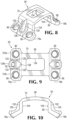
- Figures 8-12 show various views of retainer 56, which may have reflectional symmetry.
- the retainer may have a body 76, defining recess 80, and mounting regions 78a, 78b projecting from opposite sides of the body.
- the body may be generally U-shaped in end view and cross-section (see Figure 10 ), with a top portion 98 interconnecting a pair of depending legs 120.
- Each mounting region may include a foot formed on the end of each leg and configured to be disposed on bone.
- Each leg and attached mounting region (or foot) form a lateral portion 100 of the retainer (also see Figure 6 ).
- Each foot may be divided by openings, such as slits 122, into a plurality of mounting sections or tabs 124a, 124b, 124c, each defining a respective aperture (i.e., aperture 86 or 92) (see Figure 9 ).
- mounting tab 124b to receive line 94 is located between a pair of mounting tabs 124a, 124c to receive respective fasteners 82.
- the presence of more than one mounting tab in the mounting region can be advantageous because this configuration allows the tabs to be deformed independently of one another (e.g., to adjust the orientation of at least one tab), and to have a different resistance to deformation from one another.
- each mounting tab 124b is strengthened and stabilized by a pair of ribs 126 that protrude from the outer side of each leg and extend continuously to the mounting tab (see Figures 8 and 9 ).
- Ribs 126 also or alternatively may form opposite sides of a channel 128 that joins aperture 92. The channel may guide placement of a stop member 96a or 96b into aperture 92 during installation of the retainer and/or limit excessive movement of the stop member.
- FIGS 11 and 12 further illustrate the different orientations of apertures 86 and 92.
- Each mounting region or foot has at least one inner surface region 130 to face bone, and at least one lateral surface regions 132 forming a lateral edge of the retainer.
- the bottom end of each aperture 86 may be formed at least predominantly in an inner surface region 130, while the bottom end of each aperture 92 may be formed at least predominantly in a lateral surface region 132.
- Retainer 56 may have a window 134 defined as a large opening by top portion 98.
- the presence of the window increases the flexibility of the retainer, to facilitate deformation of the retainer that may be needed when the retainer is mated with the plate (see above).
- the window may be omitted to increase the strength of the retainer (see Figure 13 ).
- FIGS 14-16 show further aspects of stop members 96a, 96b and exemplary relationships between the stop members, retainer 56, and line 94.
- Each stop member may be sized to prevent complete passage of the stop member through aperture 92.
- One or both stop members may be a sleeve defining a through-bore 136 sized in correspondence with the diameter of line 94, to allow the line to slide through the sleeve.
- the stop member may have an enlarged bearing portion 138, which may be spherical, to contact a complementary wall region 140 of aperture 92.
- the sleeve and retainer may be configured to permit bearing portion 138 to slide on wall region 140 of aperture 92 through a range of orientations of a long axis 142 defined by the stop member.
- the stop member also may have a crimp portion 144 at which the stop member is configured to be crimped.
- the crimp portion may have a smaller maximum diameter than bearing portion 138.
- the crimp portion may be non-spherical, and may be elongated and/or cylindrical.
- each stop member may be installed in either of two opposite orientations on line 94 and/or the stop members may be inverted with respect to one another when installed.
- Figures 14 and 15 show an exemplary structure for aperture 92.
- the aperture may have concave spherical wall region 140 disposed outward (along through-axis 108) of a cylindrical region 146, which, like aperture 86, may have an internal thread 148. (The presence of an internal thread may permit aperture 92 to be used alternatively with fasteners 82 and spanning member 84.
- Channel 128 may extend continuously from wall region 140 and may be cylindrical, with the same radius of curvature as wall region 140.
- Figures 14 and 15 also illustrate exemplary configurations for stop members 96a and 96b in respective mounting regions 78a and 78b of retainer 56.
- the stop members may be inverted relative to one another, as shown, to position crimp portion 144 below ( Figure 14 ) or above ( Figure 15 ) bearing portion 138. In other embodiments, the stop members may not be identical to one another.
- Stop member 96a (or a different stop member) may be pre-attached to line 94, such as by deforming crimp portion 144, optionally before either end region of the line is passed through aperture 92.
- the stop member may be oriented such that crimp portion 144 is farther than bearing portion 138 from a first end region 150 of the line, and closer than bearing portion 138 to a longitudinally central section of the line. Accordingly, in the installed configuration of Figure 14 , bearing portion 138 is in contact with spherical wall region 140 of aperture 92 above crimp portion 144.
- the crimp portion may be disposed adjacent cylindrical region 146 of aperture 92 and may project out of the lower end of the aperture. The orientation of stop member 96a minimizes tissue irritation.
- Stop member 96b may be attached to line 94 after stop member 96a is located in corresponding aperture 92.
- a second, opposite end region 152 of line 94 may be fed around the bone, and through aperture 92 and stop member 96b.
- the line may be tensioned, and crimp portion 144 deformed to lock the stop member to the line.
- Line 94 then may be cut to remove at least part of second end region 152, if any, that protrudes from crimp portion 144 of stop member 96b.
- Each stop member may or may not be permitted to pivot about a center of curvature of bearing portion 138. This pivotal motion permits line 94 to more closely follow the contour of the bone near the retainer and allows the stop member to be operatively engaged with the wall of aperture 92 in a range of orientations.
- the outer diameter of crimp portion 144 may be only slightly less than the inner diameter of aperture 92 at cylindrical region 146, to restrict pivotal motion of the bearing portion, or may be significantly less to permit pivotal motion.
- the diameter of line 94 is significantly less than the corresponding inner diameter of aperture 92 at cylindrical region 146, allowing pivotal motion of stop member 96b to change the orientation at which line 94 extends from retainer 56.
- This section describes exemplary methods of bone fixation and plate attachment implemented with the systems of the present disclosure.
- the method steps of this section may be performed in any suitable order and combination, and may be modified by, or combined with, any other suitable aspects of the present disclosure.
- a bone to be fixed may be selected.
- the method may be performed on any suitable bone, and on any suitable portion thereof, such as a proximal portion, a central portion, a distal portion, or a combination thereof, among others.
- Exemplary bones that may be selected include a long bone of a limb, such as a femur, tibia, fibula, humerus, radius, or ulna.
- the bone may have any suitable discontinuity or structural weakness, such as at least one fracture, cut, nonunion, or the like.
- the bone may contain at least a portion of an implant in a medullary canal of the bone.
- the implant may be a prosthesis this is attached to the bone, replaces a missing portion of the bone, and/or provides an articulation surface of a joint.
- the implant alternatively may be an intramedullary nail.
- An incision may be created through overlying soft tissue to access the selected bone.
- the bone may be manipulated to reposition bone fragments (e.g., to approximate the relative anatomical location of the fragments), such as to set a fracture.
- Manipulation of bone fragments may be performed before and/or after the incision is created.
- a plate may be selected for stabilizing the bone.
- the plate may be elongated and/or may have any combination of the plate features described elsewhere herein.
- the plate may be described as a main plate.
- the plate may be placed through the incision and onto the bone, such that the plate spans a discontinuity in the bone.
- the plate may be attached to the bone with one or more fasteners, such as at least one screw, peg, pin, wire, cable, rivet, and/or the like.
- Each fastener independently may extend into bone directly under the plate from an aperture (a through-hole) thereof (e.g., in the case of a screw, peg, or pin), or may extend over the plate and around the bone (e.g., in the case of a wire or cable).
- the fastener may engage the plate, and may or may not lock to the plate, such as via threaded engagement.
- the plate may be attached provisionally to the bone with at least one tool, such as at least one clamp, before the plate is attached with the one or more fasteners and/or one or more encircling assemblies including a retainer (see below).
- At least one retainer may be selected for attaching the plate to the bone, and a suitable longitudinal position for each retainer along the plate may be selected.
- the number and position(s) of retainers to be used in the method may be selected at any suitable time, such as before and/or after attaching the plate to the bone with one or more fasteners (and/or one or more tools) that engage the plate.
- positions for retainers may be based on one or more locations at which the one or more fasteners are engaged with the plate, and may be offset along the plate from these locations, namely, at longitudinal positions of the plate at which no fasteners attach the plate to bone.
- Each retainer may be a supplemental plate.
- the selected retainer may be placed onto the plate, optionally after the plate has been disposed on the bone and attached to the bone with one or more fasteners and/or tools.
- the retainer may be mated with the plate at a pre-selected target position along the plate, or the retainer may be mated at a longitudinally offset position of the plate and then moved longitudinally along the plate to the target position, among others.
- One or more fasteners for the retainer may be selected.
- the fasteners may be selected from a set of fasteners including at least linear fastener and at least one spanning member.
- Each fastener selected for the retainer may be operatively disposed to couple the retainer to the bone.
- At least one linear fastener e.g., a screw, pin, peg, rivet, etc.
- the linear fastener may engage the retainer, and may or may not lock to the aperture, such as via threaded engagement.
- the linear fastener avoids (i.e., does not extend through) the plate.
- the retainer may have a pair of mounting regions (see Section I), and at least one threaded fastener may be operatively disposed in an aperture of each mounting region.
- At least two threaded fasteners may be operatively disposed in at least one or both of the mounting regions.
- a spanning member also or alternatively may be connected operatively to the retainer, such that the retainer and spanning member collectively encircle the bone.
- a spanning member selected for installation may include (i) a line having a first stop member pre-mounted to a first end region of the line and (ii) a second stop member that is separate from, and not yet assembled with, the line.
- the line may be fed through a first aperture of a first mounting region of the retainer, starting at a second end region of the line opposite the first end region, until the first stop member contacts the retainer at the first aperture to restrict advancement of the line through the first aperture.
- the second end region may be fed around the bone and through a second aperture of a second mounting region of the retainer.
- the second stop member may be placed onto the second end region of the line and into the second aperture, the line tensioned, and the second stop member crimped to lock the second stop member to the line.
- both stop members may be seated in their respective apertures and collectively may prevent release of tension on the line.
- the line may be cut to remove a length of the line that is protruding from the top of the second stop member.
- the plates, retainers, fasteners, lines, and stop members of the present disclosure may have any suitable composition. Each may be formed independently and at least partially or completely of any suitable biocompatible material(s) and/or bioresorbable (bioabsorbable) material(s).
- suitable biocompatible materials include (1) metal (for example, titanium or titanium alloy, cobalt-chrome alloy, stainless steel, etc.); (2) polymer/plastic (for example, ultra-high molecular weight polyethylene (UHMWPE), polymethylmethacrylate (PMMA), polytetrafluoroethylene (PTFE), polyetheretherketone (PEEK), and/or PMMA/polyhydroxyethylmethacrylate (PHEMA)); (3) bioresorbable material or polymer/plastic (for example, polymers of ⁇ -hydroxy carboxylic acids (e.g., polylactic acid (such as PLLA, PDLLA, and/or PDLA), polyglycolic acid, lactide/glycolide copolymers, etc.), poly
Landscapes
- Health & Medical Sciences (AREA)
- Orthopedic Medicine & Surgery (AREA)
- Surgery (AREA)
- Life Sciences & Earth Sciences (AREA)
- Heart & Thoracic Surgery (AREA)
- Nuclear Medicine, Radiotherapy & Molecular Imaging (AREA)
- Engineering & Computer Science (AREA)
- Biomedical Technology (AREA)
- Neurology (AREA)
- Medical Informatics (AREA)
- Molecular Biology (AREA)
- Animal Behavior & Ethology (AREA)
- General Health & Medical Sciences (AREA)
- Public Health (AREA)
- Veterinary Medicine (AREA)
- Surgical Instruments (AREA)
- Prostheses (AREA)
Claims (9)
- - Système de fixation osseuse (50), comprenant :- une plaque allongée (52) conçue pour être disposée longitudinalement sur un os (58) ;- un organe de retenue (56) ayant un corps (76) interconnectant une paire de régions de montage (78a, 78b), le corps définissant un renfoncement (80), chaque région de montage définissant une première ouverture (92) et une seconde ouverture (86), l'organe de retenue étant conçu pour être accouplé à la plaque pour positionner une section de la plaque dans le renfoncement de telle sorte que l'organe de retenue chevauche la plaque ;- un cordon (94) conçu pour s'étendre entre les premières ouvertures, de telle sorte que l'organe de retenue et le cordon encerclent collectivement la plaque et l'os, le cordon comprenant un fil et/ou un câble ; et- une paire d'éléments d'arrêt (96a, 96b) conçus pour être reçus sur chaque région d'extrémité du cordon, empêchant par là la région d'extrémité de passer à travers les premières ouvertures des régions de montage ; la première ouverture de chaque région de montage définissant un axe traversant (108) orienté tangentiellement à l'os pour guider le cordon (94) dans une direction périphérique sur l'os, et la seconde ouverture de chaque région de montage définissant un axe traversant (110) qui passe à travers des côtés opposés de l'os tout en évitant un canal médullaire (106) de celui-ci.
- - Système selon la revendication 1, dans lequel la seconde ouverture de chaque région de montage comporte un filetage interne, et dans lequel le système comprend en outre une pluralité d'organes de fixation (82) ayant chacun un filetage externe qui est complémentaire du filetage interne.
- - Système selon l'une quelconque des revendications 1 à 2, dans lequel l'accouplement de l'organe de retenue avec la plaque relie l'organe de retenue à la plaque, et dans lequel la plaque définit une paire de pistes longitudinales (102) conçues pour permettre à l'organe de retenue de coulisser le long de la plaque après que l'organe de retenue a été relié à la plaque par accouplement.
- - Système selon la revendication 3, dans lequel l'organe de retenue est conçu pour être relié à la plaque par l'intermédiaire d'une liaison par encliquetage.
- - Système selon la revendication 3 ou la revendication 4, dans lequel l'organe de retenue est conçu pour être déformé lorsque l'organe de retenue est accouplé à la plaque.
- - Système selon l'une quelconque des revendications 1 à 5, dans lequel l'élément d'arrêt comprend une partie de sertissage (144) et une partie sphérique (138), dans lequel la partie de sertissage est conçue pour être sertie pour verrouiller l'élément d'arrêt au cordon, et dans lequel la première ouverture de la région de montage associée a une région de paroi sphérique (140) qui est complémentaire de la partie sphérique de l'élément d'arrêt.
- - Système selon l'une quelconque des revendications 3 à 6, dans lequel la paire de pistes longitudinales comprend une paire de sillons longitudinaux, et dans lequel l'organe de retenue définit une paire de saillies (104) conçues pour être reçues dans la paire de sillons longitudinaux lorsque l'organe de retenue est accouplé à la plaque.
- - Système selon l'une quelconque des revendications 2 à 7, dans lequel la pluralité d'organes de fixation est un premier ensemble d'organes de fixation filetés, et dans lequel le système comprend en outre un second ensemble d'organes de fixation filetés, chacun étant conçu pour être reçu dans la seconde ouverture de l'une ou l'autre région de montage et n'ayant pas de filetage externe qui est complémentaire du filetage interne.
- - Système selon l'une quelconque des revendications 2 à 8, dans lequel l'élément d'arrêt a un diamètre maximal qui est supérieur à un diamètre minimal de la première ouverture d'au moins l'une des régions de montage.
Applications Claiming Priority (2)
| Application Number | Priority Date | Filing Date | Title |
|---|---|---|---|
| US201662405646P | 2016-10-07 | 2016-10-07 | |
| PCT/US2017/055434 WO2018067884A1 (fr) | 2016-10-07 | 2017-10-05 | Système et procédé de fixation osseuse à l'aide d'une plaque chevauchée par un élément de retenue |
Publications (3)
| Publication Number | Publication Date |
|---|---|
| EP3522802A1 EP3522802A1 (fr) | 2019-08-14 |
| EP3522802A4 EP3522802A4 (fr) | 2020-06-24 |
| EP3522802B1 true EP3522802B1 (fr) | 2024-10-23 |
Family
ID=61830415
Family Applications (1)
| Application Number | Title | Priority Date | Filing Date |
|---|---|---|---|
| EP17859229.1A Active EP3522802B1 (fr) | 2016-10-07 | 2017-10-05 | Système de fixation osseuse à l'aide d'une plaque chevauchée par un élément de retenue |
Country Status (4)
| Country | Link |
|---|---|
| US (1) | US10675071B2 (fr) |
| EP (1) | EP3522802B1 (fr) |
| ES (1) | ES2991890T3 (fr) |
| WO (1) | WO2018067884A1 (fr) |
Families Citing this family (6)
| Publication number | Priority date | Publication date | Assignee | Title |
|---|---|---|---|---|
| US11452553B1 (en) * | 2014-04-14 | 2022-09-27 | Avanti Orthopaedics, LLC | Load sharing bone plate |
| US10716682B2 (en) | 2017-07-19 | 2020-07-21 | Acumed Llc | Orthopedic alignment guide |
| CA3078902A1 (fr) * | 2017-11-30 | 2019-06-06 | DePuy Synthes Products, Inc. | Pince de fixation de fracture osseuse avec adaptabilite de remodelage osseux |
| WO2021144128A1 (fr) * | 2020-01-17 | 2021-07-22 | Westfaelische Wilhelms-Universitaet Muenster | Système de réparation osseuse |
| US11452552B1 (en) * | 2021-05-07 | 2022-09-27 | Avanti Orthopaedics Llc | Augmented spanning fixation bone plate assembly |
| EP4387545A4 (fr) * | 2021-08-17 | 2025-06-11 | PS Ortho LLC | Dispositifs, systèmes et procédés de fixation osseuse |
Family Cites Families (51)
| Publication number | Priority date | Publication date | Assignee | Title |
|---|---|---|---|---|
| US3842825A (en) | 1973-11-12 | 1974-10-22 | R Wagner | Hip fixation device |
| GB1517161A (en) | 1975-08-21 | 1978-07-12 | Raghava M | Implant apparatus for repairing bone fractures |
| DE8628766U1 (de) | 1986-10-25 | 1986-12-11 | Mecron Medizinische Produkte Gmbh, 1000 Berlin | Knochenplatte |
| SU1634260A1 (ru) | 1987-06-19 | 1991-03-15 | Московский медицинский стоматологический институт им.Н.А.Семашко | Устройство дл остеосинтеза межвертельной области бедра |
| US5151103A (en) | 1987-11-03 | 1992-09-29 | Synthes (U.S.A.) | Point contact bone compression plate |
| US4973332A (en) | 1988-09-12 | 1990-11-27 | Hospital For Joint Diseases | Attachment for femur sliding screw plate |
| US5116335A (en) | 1989-09-18 | 1992-05-26 | Hannon Gerard T | Intramedullary hybrid nail and instrumentation for installation and removal |
| US5190545A (en) * | 1991-08-27 | 1993-03-02 | Pfizer Hospital Products Group, Inc. | Cerclage wire positioning insert |
| GB9206018D0 (en) * | 1992-03-19 | 1992-04-29 | Dall Desmond Meiring | Bone fixation system |
| US6001099A (en) | 1998-06-08 | 1999-12-14 | Huebner; Randall J. | Bone plate with varying rigidity |
| FR2704420A1 (fr) | 1993-04-27 | 1994-11-04 | Innovations Technologiques Ste | Bride pour dispositif de fixation spinale. |
| CN2169386Y (zh) | 1993-09-03 | 1994-06-22 | 湖南医科大学附属湘雅医院 | 三维接骨板 |
| GB2331244A (en) | 1997-11-18 | 1999-05-19 | Univ Hull | Fracture fixation devices |
| WO1999065412A1 (fr) | 1998-06-18 | 1999-12-23 | Pioneer Laboratories, Inc. | Systeme de fixation spinal |
| US6224602B1 (en) | 1999-10-11 | 2001-05-01 | Interpore Cross International | Bone stabilization plate with a secured-locking mechanism for cervical fixation |
| US6872210B2 (en) | 2001-02-23 | 2005-03-29 | James P. Hearn | Sternum fixation device |
| CA2443269A1 (fr) | 2001-04-04 | 2002-10-31 | Lawrence G. Rapp | Structure de manchon mobile permettant de maintenir une relation spatiale entre des vertebres |
| US8231662B2 (en) | 2006-10-17 | 2012-07-31 | Acumed Llc | Bone fixation with a strut-stabilized bone plate |
| US20050240187A1 (en) | 2004-04-22 | 2005-10-27 | Huebner Randall J | Expanded fixation of bones |
| US6520965B2 (en) * | 2001-05-23 | 2003-02-18 | Alan Chervitz | Apparatus and method for orthopedic fixation |
| US7041105B2 (en) | 2001-06-06 | 2006-05-09 | Sdgi Holdings, Inc. | Dynamic, modular, multilock anterior cervical plate system having detachably fastened assembleable and moveable segments |
| US6755831B2 (en) | 2001-11-30 | 2004-06-29 | Regents Of The University Of Minnesota | Wrist surgery devices and techniques |
| US7250054B2 (en) * | 2002-08-28 | 2007-07-31 | Smith & Nephew, Inc. | Systems, methods, and apparatuses for clamping and reclamping an orthopedic surgical cable |
| KR101081269B1 (ko) | 2002-11-19 | 2011-11-08 | 어큠드 엘엘씨 | 조정가능한 본 플레이트 |
| EP1464295A3 (fr) * | 2003-04-01 | 2006-04-26 | Zimmer GmbH | Implant |
| US7635365B2 (en) | 2003-08-28 | 2009-12-22 | Ellis Thomas J | Bone plates |
| US20050049595A1 (en) | 2003-09-03 | 2005-03-03 | Suh Sean S. | Track-plate carriage system |
| US8328854B2 (en) | 2004-02-10 | 2012-12-11 | Atlas Spine, Inc. | Cervical plate ratchet pedicle screws |
| US7604638B2 (en) | 2004-06-21 | 2009-10-20 | Depuy Spine, Inc. | Instruments and methods for holding a bone plate |
| DE602005004375T2 (de) | 2005-03-11 | 2009-01-22 | Orthofix S.R.L., Bussolengo | Vorrichtung zur Osteosynthese von proximalen Oberarmfrakturen |
| WO2007037774A1 (fr) | 2005-04-26 | 2007-04-05 | Innovative Spinal Design | Plaque cervicale dynamique |
| US20060276896A1 (en) * | 2005-06-02 | 2006-12-07 | Medicinelodge, Inc. | Bone implants with integrated line locks |
| US8226693B2 (en) | 2006-06-16 | 2012-07-24 | Reimels William J | Bone bridge providing dynamic compression on bone fractures |
| WO2008019397A2 (fr) | 2006-08-11 | 2008-02-14 | Archus Orthopedics, Inc. | Connexion polyaxiale de rondelle inclinée pour une prothèse de colonne vertébrale dynamique |
| EA014509B1 (ru) | 2006-08-15 | 2010-12-30 | Свисмедтекселюшнз Аг | Вертельная ретенционная пластинка |
| CN101854873B (zh) * | 2007-11-13 | 2013-03-13 | 新特斯有限责任公司 | 假体周围骨折修复 |
| WO2009148762A2 (fr) * | 2008-05-09 | 2009-12-10 | Skeletal Dynamics Llc | Plaque osseuse façonnable, appareil de serrage, système d’ostéotomie et procédé pour la reconstruction d’un os |
| US8486114B2 (en) | 2008-10-10 | 2013-07-16 | Acute Innovations Llc | Cerclage system for bone |
| US9999456B2 (en) * | 2011-05-10 | 2018-06-19 | DePuy Synthes Products, Inc. | Bone fracture fixation clamp |
| US8728082B2 (en) * | 2011-05-26 | 2014-05-20 | Biomet Manufacturing, Llc | Bone plate positioning scaffold |
| JP6240076B2 (ja) * | 2011-09-30 | 2017-11-29 | アキュート・イノヴェーションズ・エルエルシー | 対向する取付け部分を備えた骨固定システム |
| US20130261674A1 (en) * | 2012-03-30 | 2013-10-03 | Daniel Duane Fritzinger | Bone plate positioning device |
| US9138245B2 (en) | 2013-02-27 | 2015-09-22 | Biomet C.V. | Jig with guide adapted to lock relative to both of threaded holes and non-threaded slots in a bone plate |
| US9138267B2 (en) | 2013-02-27 | 2015-09-22 | Biomet C.V. | Periprosthetic plating system with compressive plate and transverse bridge plate |
| US9138268B2 (en) * | 2013-02-27 | 2015-09-22 | Biomet C.V. | Periprosthetic fracture repair system including discrete stabilized crimp lugs for cerclage cable and tool therefor |
| US9138269B2 (en) | 2013-02-27 | 2015-09-22 | Biomet C.V. | Periprosthetic plating system including plate with integrated cable retaining feature |
| US9138244B2 (en) | 2013-02-27 | 2015-09-22 | Biomet C.V. | Dynamic compression plate |
| US9707025B2 (en) | 2013-02-27 | 2017-07-18 | Biomet C.V. | Cable tensioner for a periprosthetic repair system |
| DE102013104887B4 (de) * | 2013-05-13 | 2021-03-18 | Aap Implantate Ag | Osteosyntheseplatte sowie Segment für eine Osteosyntheseplatte |
| US20160143663A1 (en) * | 2014-11-24 | 2016-05-26 | Stryker European Holdings I, Llc | Strut plate and cabling system |
| KR101625177B1 (ko) * | 2016-01-07 | 2016-06-07 | 주식회사 지에스엠코리아 | 대퇴골 고정용 임플란트 |
-
2017
- 2017-10-05 EP EP17859229.1A patent/EP3522802B1/fr active Active
- 2017-10-05 WO PCT/US2017/055434 patent/WO2018067884A1/fr not_active Ceased
- 2017-10-05 US US15/726,312 patent/US10675071B2/en active Active
- 2017-10-05 ES ES17859229T patent/ES2991890T3/es active Active
Also Published As
| Publication number | Publication date |
|---|---|
| ES2991890T3 (es) | 2024-12-05 |
| WO2018067884A1 (fr) | 2018-04-12 |
| EP3522802A4 (fr) | 2020-06-24 |
| US20180098802A1 (en) | 2018-04-12 |
| EP3522802A1 (fr) | 2019-08-14 |
| US10675071B2 (en) | 2020-06-09 |
Similar Documents
| Publication | Publication Date | Title |
|---|---|---|
| US10675071B2 (en) | System and method for bone fixation using a plate straddled by a retainer | |
| US20220160409A1 (en) | Distal radius stabilization system | |
| US7951178B2 (en) | Bone plates with hybrid apertures | |
| US11896270B2 (en) | Systems and methods for using polyaxial plates | |
| EP2385800B1 (fr) | Système ancrage-dans-ancrage pour fixation osseuse | |
| US20050234458A1 (en) | Expanded stabilization of bones | |
| US10743923B2 (en) | Fixation system and method for Hoffa fractures | |
| EP3381383A1 (fr) | Système de stabilisation de l'humérus proximal | |
| US20070173840A1 (en) | Bone plate with cover | |
| US20220240991A1 (en) | Distal radius stabilization system | |
| EP3735192B1 (fr) | Fixation osseuse avec une plaque et un coupleur reliés par des éléments flexibles | |
| EP4051144B1 (fr) | Système de plaque osseuse périprothétique | |
| US12357358B2 (en) | Periprosthetic bone plate | |
| EP3453350A1 (fr) | Systèmes de stabilisation de poignet | |
| EP3868313B1 (fr) | Système de stabilisation de rayon distal | |
| CN115461004B (en) | Bone plate around prosthesis | |
| CN115397345B (en) | Bone plate with length-adjusting elongated holes | |
| WO2025259470A1 (fr) | Clou intramédullaire orthopédique et système de plaque d'ostéosynthèse | |
| CN116761564A (zh) | 用于假体周围骨板的靶向系统 |
Legal Events
| Date | Code | Title | Description |
|---|---|---|---|
| STAA | Information on the status of an ep patent application or granted ep patent |
Free format text: STATUS: THE INTERNATIONAL PUBLICATION HAS BEEN MADE |
|
| PUAI | Public reference made under article 153(3) epc to a published international application that has entered the european phase |
Free format text: ORIGINAL CODE: 0009012 |
|
| STAA | Information on the status of an ep patent application or granted ep patent |
Free format text: STATUS: REQUEST FOR EXAMINATION WAS MADE |
|
| 17P | Request for examination filed |
Effective date: 20190502 |
|
| AK | Designated contracting states |
Kind code of ref document: A1 Designated state(s): AL AT BE BG CH CY CZ DE DK EE ES FI FR GB GR HR HU IE IS IT LI LT LU LV MC MK MT NL NO PL PT RO RS SE SI SK SM TR |
|
| AX | Request for extension of the european patent |
Extension state: BA ME |
|
| DAV | Request for validation of the european patent (deleted) | ||
| DAX | Request for extension of the european patent (deleted) | ||
| REG | Reference to a national code |
Ref country code: DE Free format text: PREVIOUS MAIN CLASS: A61B0017580000 Ref country code: DE Ref legal event code: R079 Ref document number: 602017085699 Country of ref document: DE Free format text: PREVIOUS MAIN CLASS: A61B0017580000 Ipc: A61B0017800000 |
|
| A4 | Supplementary search report drawn up and despatched |
Effective date: 20200527 |
|
| RIC1 | Information provided on ipc code assigned before grant |
Ipc: A61B 17/82 20060101ALI20200519BHEP Ipc: A61B 17/84 20060101ALI20200519BHEP Ipc: A61B 17/80 20060101AFI20200519BHEP |
|
| STAA | Information on the status of an ep patent application or granted ep patent |
Free format text: STATUS: EXAMINATION IS IN PROGRESS |
|
| 17Q | First examination report despatched |
Effective date: 20230515 |
|
| P01 | Opt-out of the competence of the unified patent court (upc) registered |
Effective date: 20230602 |
|
| GRAP | Despatch of communication of intention to grant a patent |
Free format text: ORIGINAL CODE: EPIDOSNIGR1 |
|
| STAA | Information on the status of an ep patent application or granted ep patent |
Free format text: STATUS: GRANT OF PATENT IS INTENDED |
|
| INTG | Intention to grant announced |
Effective date: 20240723 |
|
| GRAS | Grant fee paid |
Free format text: ORIGINAL CODE: EPIDOSNIGR3 |
|
| GRAA | (expected) grant |
Free format text: ORIGINAL CODE: 0009210 |
|
| STAA | Information on the status of an ep patent application or granted ep patent |
Free format text: STATUS: THE PATENT HAS BEEN GRANTED |
|
| AK | Designated contracting states |
Kind code of ref document: B1 Designated state(s): AL AT BE BG CH CY CZ DE DK EE ES FI FR GB GR HR HU IE IS IT LI LT LU LV MC MK MT NL NO PL PT RO RS SE SI SK SM TR |
|
| REG | Reference to a national code |
Ref country code: GB Ref legal event code: FG4D |
|
| REG | Reference to a national code |
Ref country code: CH Ref legal event code: EP |
|
| REG | Reference to a national code |
Ref country code: DE Ref legal event code: R096 Ref document number: 602017085699 Country of ref document: DE |
|
| REG | Reference to a national code |
Ref country code: IE Ref legal event code: FG4D |
|
| REG | Reference to a national code |
Ref country code: ES Ref legal event code: FG2A Ref document number: 2991890 Country of ref document: ES Kind code of ref document: T3 Effective date: 20241205 |
|
| REG | Reference to a national code |
Ref country code: LT Ref legal event code: MG9D |
|
| REG | Reference to a national code |
Ref country code: NL Ref legal event code: MP Effective date: 20241023 |
|
| REG | Reference to a national code |
Ref country code: AT Ref legal event code: MK05 Ref document number: 1734186 Country of ref document: AT Kind code of ref document: T Effective date: 20241023 |
|
| PG25 | Lapsed in a contracting state [announced via postgrant information from national office to epo] |
Ref country code: NL Free format text: LAPSE BECAUSE OF FAILURE TO SUBMIT A TRANSLATION OF THE DESCRIPTION OR TO PAY THE FEE WITHIN THE PRESCRIBED TIME-LIMIT Effective date: 20241023 |
|
| PG25 | Lapsed in a contracting state [announced via postgrant information from national office to epo] |
Ref country code: NL Free format text: LAPSE BECAUSE OF FAILURE TO SUBMIT A TRANSLATION OF THE DESCRIPTION OR TO PAY THE FEE WITHIN THE PRESCRIBED TIME-LIMIT Effective date: 20241023 |
|
| PG25 | Lapsed in a contracting state [announced via postgrant information from national office to epo] |
Ref country code: IS Free format text: LAPSE BECAUSE OF FAILURE TO SUBMIT A TRANSLATION OF THE DESCRIPTION OR TO PAY THE FEE WITHIN THE PRESCRIBED TIME-LIMIT Effective date: 20250223 Ref country code: PT Free format text: LAPSE BECAUSE OF FAILURE TO SUBMIT A TRANSLATION OF THE DESCRIPTION OR TO PAY THE FEE WITHIN THE PRESCRIBED TIME-LIMIT Effective date: 20250224 Ref country code: HR Free format text: LAPSE BECAUSE OF FAILURE TO SUBMIT A TRANSLATION OF THE DESCRIPTION OR TO PAY THE FEE WITHIN THE PRESCRIBED TIME-LIMIT Effective date: 20241023 |
|
| PG25 | Lapsed in a contracting state [announced via postgrant information from national office to epo] |
Ref country code: FI Free format text: LAPSE BECAUSE OF FAILURE TO SUBMIT A TRANSLATION OF THE DESCRIPTION OR TO PAY THE FEE WITHIN THE PRESCRIBED TIME-LIMIT Effective date: 20241023 |
|
| PG25 | Lapsed in a contracting state [announced via postgrant information from national office to epo] |
Ref country code: BG Free format text: LAPSE BECAUSE OF FAILURE TO SUBMIT A TRANSLATION OF THE DESCRIPTION OR TO PAY THE FEE WITHIN THE PRESCRIBED TIME-LIMIT Effective date: 20241023 |
|
| PG25 | Lapsed in a contracting state [announced via postgrant information from national office to epo] |
Ref country code: NO Free format text: LAPSE BECAUSE OF FAILURE TO SUBMIT A TRANSLATION OF THE DESCRIPTION OR TO PAY THE FEE WITHIN THE PRESCRIBED TIME-LIMIT Effective date: 20250123 |
|
| PG25 | Lapsed in a contracting state [announced via postgrant information from national office to epo] |
Ref country code: GR Free format text: LAPSE BECAUSE OF FAILURE TO SUBMIT A TRANSLATION OF THE DESCRIPTION OR TO PAY THE FEE WITHIN THE PRESCRIBED TIME-LIMIT Effective date: 20250124 Ref country code: LV Free format text: LAPSE BECAUSE OF FAILURE TO SUBMIT A TRANSLATION OF THE DESCRIPTION OR TO PAY THE FEE WITHIN THE PRESCRIBED TIME-LIMIT Effective date: 20241023 Ref country code: AT Free format text: LAPSE BECAUSE OF FAILURE TO SUBMIT A TRANSLATION OF THE DESCRIPTION OR TO PAY THE FEE WITHIN THE PRESCRIBED TIME-LIMIT Effective date: 20241023 |
|
| PG25 | Lapsed in a contracting state [announced via postgrant information from national office to epo] |
Ref country code: PL Free format text: LAPSE BECAUSE OF FAILURE TO SUBMIT A TRANSLATION OF THE DESCRIPTION OR TO PAY THE FEE WITHIN THE PRESCRIBED TIME-LIMIT Effective date: 20241023 |
|
| PG25 | Lapsed in a contracting state [announced via postgrant information from national office to epo] |
Ref country code: RS Free format text: LAPSE BECAUSE OF FAILURE TO SUBMIT A TRANSLATION OF THE DESCRIPTION OR TO PAY THE FEE WITHIN THE PRESCRIBED TIME-LIMIT Effective date: 20250123 |
|
| PG25 | Lapsed in a contracting state [announced via postgrant information from national office to epo] |
Ref country code: SM Free format text: LAPSE BECAUSE OF FAILURE TO SUBMIT A TRANSLATION OF THE DESCRIPTION OR TO PAY THE FEE WITHIN THE PRESCRIBED TIME-LIMIT Effective date: 20241023 |
|
| PG25 | Lapsed in a contracting state [announced via postgrant information from national office to epo] |
Ref country code: DK Free format text: LAPSE BECAUSE OF FAILURE TO SUBMIT A TRANSLATION OF THE DESCRIPTION OR TO PAY THE FEE WITHIN THE PRESCRIBED TIME-LIMIT Effective date: 20241023 |
|
| PG25 | Lapsed in a contracting state [announced via postgrant information from national office to epo] |
Ref country code: EE Free format text: LAPSE BECAUSE OF FAILURE TO SUBMIT A TRANSLATION OF THE DESCRIPTION OR TO PAY THE FEE WITHIN THE PRESCRIBED TIME-LIMIT Effective date: 20241023 |
|
| PG25 | Lapsed in a contracting state [announced via postgrant information from national office to epo] |
Ref country code: RO Free format text: LAPSE BECAUSE OF FAILURE TO SUBMIT A TRANSLATION OF THE DESCRIPTION OR TO PAY THE FEE WITHIN THE PRESCRIBED TIME-LIMIT Effective date: 20241023 |
|
| REG | Reference to a national code |
Ref country code: DE Ref legal event code: R097 Ref document number: 602017085699 Country of ref document: DE |
|
| PG25 | Lapsed in a contracting state [announced via postgrant information from national office to epo] |
Ref country code: SK Free format text: LAPSE BECAUSE OF FAILURE TO SUBMIT A TRANSLATION OF THE DESCRIPTION OR TO PAY THE FEE WITHIN THE PRESCRIBED TIME-LIMIT Effective date: 20241023 |
|
| PG25 | Lapsed in a contracting state [announced via postgrant information from national office to epo] |
Ref country code: CZ Free format text: LAPSE BECAUSE OF FAILURE TO SUBMIT A TRANSLATION OF THE DESCRIPTION OR TO PAY THE FEE WITHIN THE PRESCRIBED TIME-LIMIT Effective date: 20241023 |
|
| PG25 | Lapsed in a contracting state [announced via postgrant information from national office to epo] |
Ref country code: IT Free format text: LAPSE BECAUSE OF FAILURE TO SUBMIT A TRANSLATION OF THE DESCRIPTION OR TO PAY THE FEE WITHIN THE PRESCRIBED TIME-LIMIT Effective date: 20241023 |
|
| PLBE | No opposition filed within time limit |
Free format text: ORIGINAL CODE: 0009261 |
|
| STAA | Information on the status of an ep patent application or granted ep patent |
Free format text: STATUS: NO OPPOSITION FILED WITHIN TIME LIMIT |
|
| PG25 | Lapsed in a contracting state [announced via postgrant information from national office to epo] |
Ref country code: SE Free format text: LAPSE BECAUSE OF FAILURE TO SUBMIT A TRANSLATION OF THE DESCRIPTION OR TO PAY THE FEE WITHIN THE PRESCRIBED TIME-LIMIT Effective date: 20241023 |
|
| 26N | No opposition filed |
Effective date: 20250724 |
|
| PGFP | Annual fee paid to national office [announced via postgrant information from national office to epo] |
Ref country code: GB Payment date: 20250821 Year of fee payment: 9 |
|
| REG | Reference to a national code |
Ref country code: CH Ref legal event code: U11 Free format text: ST27 STATUS EVENT CODE: U-0-0-U10-U11 (AS PROVIDED BY THE NATIONAL OFFICE) Effective date: 20251101 |
|
| PGFP | Annual fee paid to national office [announced via postgrant information from national office to epo] |
Ref country code: DE Payment date: 20250819 Year of fee payment: 9 |
|
| PGFP | Annual fee paid to national office [announced via postgrant information from national office to epo] |
Ref country code: CH Payment date: 20251101 Year of fee payment: 9 |
|
| PGFP | Annual fee paid to national office [announced via postgrant information from national office to epo] |
Ref country code: ES Payment date: 20251104 Year of fee payment: 9 |