EP3523078B1 - Tischsäge und splitterschutzelement - Google Patents
Tischsäge und splitterschutzelement Download PDFInfo
- Publication number
- EP3523078B1 EP3523078B1 EP17781432.4A EP17781432A EP3523078B1 EP 3523078 B1 EP3523078 B1 EP 3523078B1 EP 17781432 A EP17781432 A EP 17781432A EP 3523078 B1 EP3523078 B1 EP 3523078B1
- Authority
- EP
- European Patent Office
- Prior art keywords
- support plate
- workpiece support
- table saw
- splinter protection
- protection element
- Prior art date
- Legal status (The legal status is an assumption and is not a legal conclusion. Google has not performed a legal analysis and makes no representation as to the accuracy of the status listed.)
- Active
Links
Images

Classifications
-
- B—PERFORMING OPERATIONS; TRANSPORTING
- B23—MACHINE TOOLS; METAL-WORKING NOT OTHERWISE PROVIDED FOR
- B23D—PLANING; SLOTTING; SHEARING; BROACHING; SAWING; FILING; SCRAPING; LIKE OPERATIONS FOR WORKING METAL BY REMOVING MATERIAL, NOT OTHERWISE PROVIDED FOR
- B23D47/00—Sawing machines or sawing devices working with circular saw blades, characterised only by constructional features of particular parts
- B23D47/02—Sawing machines or sawing devices working with circular saw blades, characterised only by constructional features of particular parts of frames; of guiding arrangements for work-table or saw-carrier
- B23D47/025—Sawing machines or sawing devices working with circular saw blades, characterised only by constructional features of particular parts of frames; of guiding arrangements for work-table or saw-carrier of tables
-
- B—PERFORMING OPERATIONS; TRANSPORTING
- B23—MACHINE TOOLS; METAL-WORKING NOT OTHERWISE PROVIDED FOR
- B23D—PLANING; SLOTTING; SHEARING; BROACHING; SAWING; FILING; SCRAPING; LIKE OPERATIONS FOR WORKING METAL BY REMOVING MATERIAL, NOT OTHERWISE PROVIDED FOR
- B23D45/00—Sawing machines or sawing devices with circular saw blades or with friction saw discs
- B23D45/06—Sawing machines or sawing devices with circular saw blades or with friction saw discs with a circular saw blade arranged underneath a stationary work-table
-
- B—PERFORMING OPERATIONS; TRANSPORTING
- B23—MACHINE TOOLS; METAL-WORKING NOT OTHERWISE PROVIDED FOR
- B23D—PLANING; SLOTTING; SHEARING; BROACHING; SAWING; FILING; SCRAPING; LIKE OPERATIONS FOR WORKING METAL BY REMOVING MATERIAL, NOT OTHERWISE PROVIDED FOR
- B23D47/00—Sawing machines or sawing devices working with circular saw blades, characterised only by constructional features of particular parts
- B23D47/04—Sawing machines or sawing devices working with circular saw blades, characterised only by constructional features of particular parts of devices for feeding, positioning, clamping, or rotating work
- B23D47/045—Sawing machines or sawing devices working with circular saw blades, characterised only by constructional features of particular parts of devices for feeding, positioning, clamping, or rotating work feeding work into engagement with the saw blade
-
- B—PERFORMING OPERATIONS; TRANSPORTING
- B27—WORKING OR PRESERVING WOOD OR SIMILAR MATERIAL; NAILING OR STAPLING MACHINES IN GENERAL
- B27G—ACCESSORY MACHINES OR APPARATUS FOR WORKING WOOD OR SIMILAR MATERIALS; TOOLS FOR WORKING WOOD OR SIMILAR MATERIALS; SAFETY DEVICES FOR WOOD WORKING MACHINES OR TOOLS
- B27G19/00—Safety guards or devices specially adapted for wood saws; Auxiliary devices facilitating proper operation of wood saws
- B27G19/10—Measures preventing splintering of sawn portions of wood
Definitions
- the invention relates to a table saw, preferably a circular table saw, with a support structure which can be placed on a base and on the upper side of which a workpiece support plate is provided, and with a saw blade which projects upwards above the workpiece support plate.
- a table saw which comprises a worktop with a support surface, a housing which supports the worktop, and a machine frame arranged below the worktop and connected to it for receiving a motor and a saw blade.
- the DE 298 09 921 U1 Describes a guide plate designed to rest on a workpiece with its underside.
- a handheld power tool such as a hand-held circular saw, is placed on the top of the guide plate and moved longitudinally along the guide plate.
- the guide plate has a base made of a suitable metal.
- the base supports a guide rail that rests against the workpiece during use.
- the guide rail and the guide lip formed by it prevent splintering of the workpiece material.
- the US 1 590 974 A Describes a weatherstrip for attaching to doors and window frames.
- the weatherstrip includes a longitudinal bead and a V-shaped longitudinal retaining piece that allows the weatherstrip to be attached to the door or window frame.
- a table saw comprising a base having a spindle for interchangeably mounting two or more saw blades, a rail attached to the base, a support slidably mounted on the rail for supporting a workpiece, a tabletop mounted on the base and having an opening facing the saw blades, and two or more inserts interchangeably engageable in the opening of the tabletop and having a recess for accommodating saw blades of different widths or thicknesses.
- the rail is preferably slidably and adjustably mounted on the base.
- the workpiece support plate is mounted displaceably in the sawing direction relative to the support structure and the saw blade and has a splinter protection element arranged on a side of the workpiece support plate facing the saw blade, which is guided past the saw blade when the workpiece support plate is displaced.
- the workpiece support plate which is mounted so that it can be moved relative to the sawblade, makes it possible to move a workpiece placed on the workpiece support plate closer to the sawblade and/or into the sawblade. This prevents the workpiece from having to be pushed over the workpiece support plate, which can reduce the risk of surface damage, such as scratches, on the side of the workpiece resting on the workpiece support plate.
- the splinter guard element on the workpiece support plate also reduces the risk of damage to the workpiece due to tearing during sawing. Because the splinter guard element is located on the movable workpiece support plate and thus moves with the movable workpiece support plate, it ensures that splinter protection is provided between the workpiece support plate and the saw blade, even in different positions of the workpiece support plate.
- the splinter protection element preferably comprises a splinter protection lip, in particular a splinter protection rubber lip.
- the splinter protection lip is expediently elongated or strip-shaped. A splinter protection element designed in this way can ensure sawing with as little tearing as possible.
- the splinter guard extends in front of the saw blade, expediently in such a way that the splinter guard is cut to size by sliding the workpiece support plate away from the saw blade when the table saw is put into operation.
- This design of the splinter guard allows the splinter guard to be precisely cut to size, so that later in operation it sits exactly against the saw blade, thus enabling tear-free sawing of the workpiece.
- the splinter protection element is removably attached to the workpiece support plate.
- the splinter protection element is attached to the workpiece support plate in such a way that it can be manually removed from the workpiece support plate, preferably without loosening a screw or other fastening element.
- the splinter protection element and the workpiece support plate are expediently designed such that the splinter protection element can be reversibly attached to and/or removed from the workpiece support plate. This design allows the splinter protection element to be replaced very easily.
- a groove is provided on the side of the workpiece support plate facing the saw blade, which receives a section of the splinter protection element.
- the groove opens at a front and/or rear side of the The splinter protection element can thus be easily pulled out of the groove and is therefore particularly easy to remove from the workpiece support plate.
- the splinter protection element is elongated.
- the splinter protection element expediently extends over the entire side of the workpiece support plate facing the saw blade.
- the length and arrangement of the splinter protection element are selected such that, in every position of the workpiece support plate in which the workpiece support plate is in the area of the saw blade and sawing of a workpiece placed on the workpiece support plate is possible, a section of the splinter protection element is located between the workpiece support plate and the saw blade, so that tear-free sawing of the workpiece is possible even in different positions of the workpiece support plate.
- the splinter protection element preferably has an arrow-shaped profile.
- the arrow-shaped profile expediently has an arrowhead section and a shaft section.
- the shaft section is accommodated in particular in the groove provided on the workpiece support plate.
- the arrowhead section is preferably located outside the groove and forms a splinter protection lip.
- an engagement structure preferably circular in shape and thickened relative to the shaft section, is provided at a distal end of the shaft section.
- the engagement structure is expediently in engagement with a complementary engagement structure of the workpiece support plate or the groove and prevents Form-fitting design allows the splinter guard to be removed from the workpiece support plate perpendicular to the sawing direction. This design ensures that the splinter guard sits sufficiently firmly in the groove during operation of the table saw, yet can still be removed relatively easily from the workpiece support plate, for example, if the splinter guard needs to be replaced.
- the table saw has coupling means.
- the coupling means are preferably suitable for providing a detachable, vertically tensile-resistant coupling with the at least one box-shaped body when the table saw forms a vertical stack together with at least one box-shaped body.
- the table saw can be stably accommodated in a vertical stack and transported in this. This improves the handling and transportability of the table saw.
- the above-described attachment of the splinter protection element directly to the movable workpiece support plate is particularly advantageous in this context because, as already mentioned above, it enables a simple and thus as compact as possible construction of the table saw.
- the external shape of the table saw expediently corresponds to the shape of a system box, so that the table saw can be accommodated in a stack of system boxes.
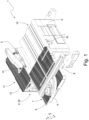
- the Figure 1 shows an exemplary embodiment of a table saw 1.
- the table saw 1 is designed as a circular table saw, but can alternatively also be designed as another table saw, for example as a table jigsaw.
- the table saw 1 extends in a vertical direction parallel to the z-axis shown in the figures, in a longitudinal direction parallel to the x-axis shown in the figures, and in a transverse direction parallel to the y-axis shown in the figures.
- the x-axis, y-axis, and z-axis are aligned orthogonally to each other.
- the table saw 1 has a support structure 2 that can be placed on a base.
- a workpiece support plate 4 is provided on the upper side of the support structure 2.
- the table saw 1 has a saw blade 5 that projects upwards above the workpiece support plate 4.
- the workpiece support plate 4 is arranged in a Movable in sawing direction y.
- the workpiece support plate 4 has a splinter protection element 6.
- the splinter protection element 6 is arranged on a side 7 of the workpiece support plate 4 facing the saw blade. The side 7 of the workpiece support plate 4 is guided past the saw blade 5 when the workpiece support plate 4 is moved.
- This design of the table saw 1 solves the problem mentioned at the beginning, namely that the risk of damage to the surface of a workpiece during handling and processing of the workpiece can be reduced by means of a table saw structure that is as simple as possible.
- the support structure 2 is box-shaped.
- the support structure 2 has four orthogonally aligned peripheral walls 8, 9, 10, 11, which are essentially closed.
- the two peripheral walls 8 and 10 lie in parallel xz planes, and the two peripheral walls 9 and 11 lie in parallel yz planes.
- the support structure 2 can alternatively be designed differently; for example, the support structure 2 can also be designed as a leg frame.
- the workpiece support plate 4 is provided on the upper side of the support structure 2.
- the workpiece support plate 4 has a rectangular support surface which faces upwards in the operating position of the table saw 1.
- the workpiece support plate 4 lies in an xy plane and is displaceably mounted on the support structure 2, so that the workpiece support plate 4 can be moved relative to the support structure 2 and relative to the Saw blade 5 can be moved in the sawing direction y or the y-direction.
- the workpiece support plate 4 can be moved into different positions in the y-direction relative to the support structure 2.
- the Figures 1 and 2 show the workpiece support plate 4 in an extended position. In the extended position, a major part of the workpiece support plate 4 is expediently located outside a horizontal outer contour of the box-shaped support structure 2.
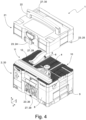
- Figure 4 shows the workpiece support plate 4 in a transport position. In the transport position, the workpiece support plate 4 is arranged flush with the horizontal outer contour of the support structure 2, so that the workpiece support plate 4 and the support structure 2 together form a box-shaped or cuboid-shaped body, which is also referred to below as the lower part 20.
- the workpiece support plate 4 can be fixed relative to the saw blade 5 or the support structure 2.
- the fixation can be adjusted, for example, via a rotary knob 33 provided on the peripheral wall 9.
- the workpiece support plate 4 can, in particular, be fixed in a position in which it is arranged in alignment with the support structure 2.
- the saw blade 5 is provided on the upper side of the support structure 2.
- the saw blade 5 extends through an opening provided in the support structure 2 and projects upwards past the workpiece support plate 4.
- the saw blade 5 lies on an imaginary line oriented in the y-direction, which divides the upper side of the support structure 2 into two x-regions in the x-direction.
- the movable workpiece support plate 4 is provided in one x-region.
- a support plate 12 is provided, which is preferably stationary relative to the support structure 2.
- the movable workpiece support plate 4 and the support plate 12 preferably occupy the same z-range, so that they lie in the same xz-plane. In the transport position of the workpiece support plate 4, the workpiece support plate 4 and the support plate 12 together form a body having a substantially rectangular horizontal outer contour.
- the saw blade 5 is preferably arranged off-center in the x-direction relative to the upper side of the support structure 2, so that the workpiece support plate 4 is longer in the x-direction than the support plate 12.
- the workpiece support plate 4 can be approximately twice as long in the x-direction as the support plate 12.
- the upper sides or support surfaces of the workpiece support plate 4 and the support plate 12 are provided with grooves.
- the upper side of the workpiece support plate 4 and/or the support plate 12 can also be provided without grooves, be flat, or have a different structure.
- the saw blade 5 is arranged in a rear region of the support structure 2.
- the support plate 12 has a rectangular recess 13 extending in the y-direction in this region.
- a splinter protection element for example a splinter protection rubber lip, can be provided on the support plate 12, in particular in the recess 13, particularly in the y-region in which the saw blade 5 or the cutting area of the saw blade 5 is located.
- the table saw 1 comprises a drive device not shown in the figures, for example an electric motor and possibly corresponding control electronics, for mechanically driving the saw blade 5.
- the drive device is arranged entirely in the support structure 2 and fastened thereto in a ready-to-use manner, so that the drive device remains in the support structure 2 during machining of the workpiece by the saw blade 5 driven by the drive device.
- the splinter protection element 6 is detachably attached to the workpiece support plate 4.
- the Figures 1 and 4 show the splinter protection element 6 in a state attached to the workpiece support plate 4, while the Figures 2 and 3 show the splinter protection element 6 in a state in which it is removed from the workpiece support plate 4.
- the splinter protection element 6 is removed from the workpiece support plate 4. As shown in the Figure 2 As shown, the splinter protection element has a splinter protection lip that extends in the y-direction.
- the splinter protection element 6 is elongated or rod-shaped, in particular strip-shaped.
- the splinter protection element is made, for example, of rubber or another flexible material.
- the splinter protection element 6 extends over the entire side 7 of the workpiece support plate 4 facing the saw blade 5.
- the splinter protection element extends over the entire width of the support structure 2 or the table saw 1.
- the splinter protection element 6 can also be designed such that it does not extend over the entire side 7 of the workpiece support plate 4. In this case, it is advantageous if the Splinter protection element 6 extends at least over the y-area of the workpiece support plate 4, which can be positioned in the cutting area of the saw blade 5.
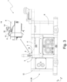
- the Figure 3 shows a front view of the table saw 1. Furthermore, the Figure 3 a detailed view of the side 7 of the workpiece support plate 4 facing the saw blade 5.
- a groove 14 for receiving the splinter protection element 6 is provided on the side 7 of the workpiece support plate 4 facing the saw blade 5.
- the side 7 is, for example, a vertical side surface of the workpiece support plate 4.
- the profile of the groove 14 extends accordingly horizontally or in the x-direction into the workpiece support plate 4.
- the groove 14 is designed to be complementary to a section of the splinter protection element 6 so that it can accommodate this section.
- the groove 14 runs, for example, across the entire width of the workpiece support plate 4; alternatively, the groove 14 can also run across only part of the width of the workpiece support plate 4. In the example shown, the groove 14 opens out at a front and a back of the workpiece support plate 4.
- the splinter protection element 6 has an arrow-shaped profile.
- the profile has an arrowhead section 15 and a shaft section 16 connected thereto.
- the arrowhead section 15 tapers in the x-direction towards the saw blade 5.
- the arrowhead section is designed such that an upper side surface 31 of the arrowhead section 15, in the inserted state of the splinter protection element 6, is arranged substantially flush with the support surface of the workpiece support plate 4.
- the upper side surface 31 lies in the same xz-plane as the support surface of the workpiece support plate 4.
- the arrowhead section 15 has a triangular profile, wherein the upper side surface 31 is aligned approximately orthogonal to a side surface 32 facing the shaft section 16.
- an engagement structure 18, which is exemplary circular or cylindrical, is provided.
- the engagement structure 18 is thickened compared to the shaft portion 16.
- the shaft portion 16 is designed to complement the groove 14 so that it can be accommodated therein.
- the arrowhead portion 15 is located outside the groove 14 and forms a splinter protection lip.
- the groove 14 is formed complementarily to the shaft portion 16.
- the groove 14 has an engagement structure 19 formed complementarily to the engagement structure 18, which engages with the engagement structure 18 in a state in which the splinter protection element 6 is attached to the workpiece support plate 4.
- the splinter protection element 6 is dimensioned such that it does not extend in front of the saw blade 5; i.e., that it does not occupy the same x-range as the saw blade 5.
- the splinter protection element 6 can also be designed such that it extends in front of the saw blade 5; i.e., that it occupies the same x-range as the saw blade. If the splinter protection element 6 is dimensioned in the latter way, it can be pushed into the saw blade 5 by sliding the workpiece support plate 4 when the table saw 5 is put into operation. In this way, the splinter protection element can be cut to fit precisely.
- the workpiece support plate 4 has a plate section 3 in the x-direction that tapers towards the saw blade 5. At the distal end of this plate section 3 is the aforementioned side 7, or the vertical side surface on which the groove 14 is provided. In the example shown, the plate section 3 tapers such that the z-extension of the side 7 essentially corresponds to the maximum z-extension of the splinter protection element 6. The part of the support surface of the workpiece support plate 4 belonging to the plate section 3 lies in the same xy plane as the remaining part of the support surface of the workpiece support plate 4.
- the Figure 4 shows the table saw 1 in a configuration in which the table saw 1 has an upper part 21 in addition to the lower part 20.
- the upper part 21 is hood-shaped and has a carrying handle 22, which is arranged, for example, on the upper side of the upper part 21.
- the upper part 21 can be placed on the lower part 20 and detachably coupled to the lower part 20 in a vertically tensile manner.
- the upper part 21 and the lower part 20 have corresponding coupling means 23, such as a rotary latch 24, tabs 25, a receptacle (not shown) for the tabs 25, and a locking anchor contour 26.
- the table saw 1 has a substantially box-shaped or cuboid-shaped basic shape.
- the external shape of the table saw 1 then corresponds to that of a system box.
- the table saw 1 has further coupling means 27 which are suitable for, in a state in which the table saw 1 forms a vertical stack together with at least one box-shaped body not shown in the figures, to provide a detachable, vertically tensile coupling with the at least one box-shaped body.
- the basic shape of the table saw 1 is defined in particular by the box-shaped support structure 2 and the upper part 21.
- the outer surfaces of the support structure 2 and the upper part 21 represent the housing or the outer housing surfaces of the table saw 1.
- the housing or the basic shape of the table saw 1 has in particular the shape of a system box.
- System boxes of a system have a base area defined in the system and have coupling means defined in the system, so that system boxes of a system can be assembled into a stable stack. System boxes are widely used, for example, as modular tool boxes for storing hand-held power tools, accessories and/or consumables. If the basic shape or the housing of the table saw is designed in the form of a system box, the transportable processing unit can be conveniently stowed and transported in a stack of system boxes.
- the coupling means 27 comprise, in particular, upper coupling means provided on the upper part 21.
- the upper coupling means are suitable for providing a releasable, vertically tensile-resistant coupling with the box-shaped body in a state in which a box-shaped body, such as another table saw 1, is stacked on the table saw 1.
- the upper coupling means comprise a movably mounted locking element 28.
- the locking element 28 is a rotary latch rotatably mounted on the upper part 21.
- the rotary latch is arranged on the front wall of the upper part 21. The rotation axis of the rotary latch runs orthogonal to the front wall.
- the coupling means 27 further comprise lower coupling means provided on the lower part 20.
- the lower coupling means are suitable for providing a detachable, vertically tensile-resistant coupling to the box-shaped body when the table saw 1 is stacked on a box-shaped body, such as another table saw 1.
- the lower coupling means comprise at least one locking anchor contour 29 fixedly arranged on the lower part 20.
- the locking anchor contour 29 is located on the front peripheral wall 8 of the lower part 20.
- the locking anchor contour 29 is designed as a locking projection and protrudes from the peripheral wall 8.
- the locking element 28 and the locking anchor contour 29 are arranged and designed such that, when two table saws 1 are stacked vertically one above the other, the locking element 28 of one table saw 1 can be brought into coupling engagement with the locking anchor contour 29 of the other table saw 1.
- the coupling means 27 may further comprise engagement structures provided on the underside and the top side of the table saw 1.
- the table saw 1 may have one or more engagement recesses 30 on the top side of the upper part 21 and one or more engagement projections corresponding to the engagement recesses on the underside of the lower part 3 (not shown in the figures).
- the engagement structures may be configured such that they contribute to the vertically secured coupling.
Landscapes
- Engineering & Computer Science (AREA)
- Mechanical Engineering (AREA)
- Life Sciences & Earth Sciences (AREA)
- Wood Science & Technology (AREA)
- Forests & Forestry (AREA)
- Sawing (AREA)
Description
- Die Erfindung betrifft eine Tischsäge, vorzugsweise eine Tischkreissäge, mit einer auf einer Unterlage abstellbaren Stützstruktur, an deren Oberseite eine Werkstück-Auflageplatte vorgesehen ist, und mit einem über die Werkstück-Auflageplatte nach oben ragenden Sägeblatt.
- Aus der Druckschrift
DE 20 2004 00912 3 U1 ist eine Tischkreissäge bekannt, die eine Arbeitsplatte mit einer Auflagefläche, ein Gehäuse, welches die Arbeitsplatte trägt, und einen unterhalb der Arbeitsplatte angeordneten und mit dieser verbundenen Maschinenrahmen zur Aufnahme eines Motors und eines Sägeblatts umfasst. - Die
DE 298 09 921 U1 beschreibt eine Führungsplatte, die dazu dient, mit ihrer Unterseite auf ein Werkstück aufgelegt zu werden. Eine Handwerkzeugmaschine, beispielsweise eine Handkreissäge, wird auf die Führungsplatten-Oberseite aufgesetzt und der Führungsplatte entlang in deren Längsrichtung bewegt. Die Führungsplatte weist einen Grundkörper auf, der aus einem geeigneten Metall besteht. Der Grundkörper trägt eine beim Gebrauch am Werkstück aufliegende Führungsleiste. Mit Hilfe der Führungsleiste und der von dieser gebildeten Führungslippe wird ein Aussplittern des Materials des Werkstücks vermieden. - Die
US 1 590 974 A beschreibt einen Wetterstreifen zum Anbringen an Türen und Fensterrahmen. Der Wetterstreifen umfasst einen Longitudinal-Wulst und ein V-förmiges Longitudinal-Halteteil, mit dem der Wetterstreifen an die Tür oder den Fensterrahmen befestigt werden kann. - Aus der
US 2009/0007743 A1 ist eine Tischsäge mit einer Basis, die eine Spindel zum auswechselbaren Befestigen von zwei oder mehr Sägeblättern aufweist, mit einer an der Basis befestigten Schiene, einem Träger, der gleitend auf der Schiene angeordnet ist, um ein Werkstück zu tragen, mit einer Tischplatte, die auf der Basis angeordnet ist und eine Öffnung aufweist, die den Sägeblättern zugewandt ist, und mit zwei oder mehr Einsätzen, die auswechselbar in die Öffnung der Tischplatte eingreifen können und eine Aussparung aufweisen, um Sägeblätter unterschiedlicher Breite oder Dicke einzupassen bekannt. Die Schiene ist vorzugsweise verschiebbar und verstellbar an der Basis befestigt. - Es ist eine Aufgabe der Erfindung, eine Tischsäge der eingangs genannten Art so zu modifizieren, dass mit einem möglichst einfachen Aufbau der Tischsäge das Risiko von Beschädigungen der Oberfläche eines Werkstücks bei der Handhabung und Bearbeitung des Werkstücks reduziert werden kann.
- Die Aufgabe wird durch die im Kennzeichen des Anspruchs 1 angegebenen Merkmale gelöst. Erfindungsgemäß ist die Werkstück-Auflageplatte relativ zur Stützstruktur und zum Sägeblatt in Sägerichtung verschiebbar gelagert und verfügt über ein Splitterschutzelement, das an einer dem Sägeblatt zugewandten Seite der Werkstück-Auflageplatte angeordnet ist, die beim Verschieben der Werkstück-Auflageplatte am Sägeblatt vorbeigeführt wird.
- Durch die relativ zum Sägeblatt verschiebbar gelagerte Werkstück-Auflageplatte wird es möglich, ein auf der Werkstück-Auflageplatte aufgelegtes Werkstück durch Verschieben der Werkstück-Auflageplatte an das Sägeblatt heranzuführen und/oder in das Sägeblatt hineinzuschieben. Auf diese Weise wird verhindert, dass das Werkstück über die Werkstück-Auflageplatte geschoben werden muss, wodurch das Risiko von Oberflächenbeschädigungen, wie beispielsweise Kratzern, an der auf der Werkstück-Auflageplatte aufliegenden Seite des Werkstücks verringert werden kann.
- Durch das an der Werkstück-Auflageplatte vorgesehene Splitterschutzelement kann darüber hinaus das Risiko einer Beschädigung des Werkstücks durch Ausriss beim Sägen verringert werden. Da das Splitterschutzelement an der verschiebbaren Werkstück-Auflageplatte angeordnet ist und folglich mit der verschiebbaren Werkstück-Auflageplatte mitgeführt wird, kann gewährleistet werden, dass auch in verschiedenen Stellungen der Werkstück-Auflageplatte ein Splitterschutz zwischen der Werkstück-Auflageplatte und dem Sägeblatt gegeben ist.
- Dadurch, dass das Splitterschutzelement direkt an der verschiebbaren Werkstück-Auflageplatte vorgesehen ist, ergibt sich ein einfacher Aufbau der Tischsäge. Insbesondere entfällt durch diese Maßnahme die Notwendigkeit, für das Splitterschutzelement eine dedizierte, ortsfest an der Stützstruktur angebrachte Halterungsstruktur zwischen dem Sägeblatt und der Werkstück-Auflageplatte vorzusehen. Folglich wird durch die Anbringung des Splitterschutzelements an der verschiebbaren Werkstück-Auflageplatte der Vorteil eines einfachen Aufbaus erzielt.
- Vorteilhafte Weiterbildungen der Erfindung sind Gegenstand der Unteransprüche.
- Vorzugsweise umfasst das Splitterschutzelement eine Splitterschutzlippe, insbesondere eine Splitterschutzgummilippe. Zweckmäßigerweise ist die Splitterschutzlippe länglich bzw. leistenförmig ausgebildet. Durch ein derart ausgebildetes Splitterschutzelement kann ein möglichst ausrissfreies Sägen gewährleistet werden.
- In bevorzugter Ausgestaltung erstreckt sich das Splitterschutzelement vor das Sägeblatt, und zwar zweckmäßigerweise derart, dass das Splitterschutzelement bei der Inbetriebnahme der Tischsäge durch Verschieben der Werkstück-Auflageplatte vom Sägeblatt zugeschnitten wird. Durch diese Ausgestaltung des Splitterschutzelements wird erzielt, dass das Splitterschutzelement passgenau zugeschnitten werden kann, so dass später im Betrieb exakt an dem Sägeblatt anliegt und dadurch ein ausrissfreies Sägen des Werkstücks ermöglicht.
- In bevorzugter Ausgestaltung ist das Splitterschutzelement abnehmbar an der Werkstück-Auflageplatte angebracht. Insbesondere ist das Splitterschutzelement derart an der Werkstück-Auflageplatte angebracht, dass es manuell, vorzugsweise ohne das Lösen einer Schraube oder einem sonstigen Befestigungselement, von der Werkstück-Auflageplatte abgenommen werden kann. Zweckmäßigerweise sind das Splitterschutzelement und die Werkstück-Auflageplatte derart ausgebildet, dass das Splitterschutzelement reversibel an die Werkstück-Auflageplatte angebracht und/oder von dieser abgenommen werden kann. Durch diese Ausgestaltung kann das Splitterschutzelement in sehr einfacher Weise ausgetauscht werden.
- Zweckmäßigerweise ist an der dem Sägeblatt zugewandten Seite der Werkstück-Auflageplatte eine Nut vorgesehen, die einen Abschnitt des Splitterschutzelements aufnimmt. Zweckmäßigerweise mündet die Nut an einer Vorder- und/oder Rückseite der Werkstück-Auflageplatte aus. Das Splitterschutzelement kann somit in einfacher Weise aus der Nut herausgezogen werden und ist folglich besonders einfach von der Werkstück-Auflageplatte abnehmbar.
- Gemäß einer bevorzugten Ausgestaltung ist das Splitterschutzelement länglich ausgebildet. Zweckmäßigerweise erstreckt sich das Splitterschutzelement über die gesamte dem Sägeblatt zugewandte Seite der Werkstück-Auflageplatte. Insbesondere sind die Länge und Anordnung des Splitterschutzelements derart gewählt, dass sich in jeder Position der Werkstück-Auflageplatte, in der sich die Werkstück-Auflageplatte im Bereich des Sägeblatts befindet und ein Sägen eines auf die Werkstück-Auflageplatte aufgelegten Werkstücks möglich ist, ein Abschnitt des Splitterschutzelements zwischen der Werkstück-Auflageplatte und dem Sägeblatt befindet, so dass auch in verschiedenen Stellungen der Werkstück-Auflageplatte ein ausrissfreies Sägen des Werkstücks erfolgen kann.
- Vorzugsweise verfügt das Splitterschutzelement über ein pfeilförmiges Profil. Das pfeilförmigen Profil weist zweckmäßigerweise einen Pfeilkopfabschnitt und einen Schaftabschnitt auf. Der Schaftabschnitt ist insbesondere in der an der Werkstück-Auflageplatte vorgesehenen Nut untergebracht. Vorzugsweise befindet sich der Pfeilkopfabschnitt außerhalb der Nut und bildet eine Splitterschutzlippe.
- Zweckmäßigerweise ist an einem distalen Ende des Schaftabschnitts eine vorzugsweise kreisförmig ausgebildete gegenüber dem Schaftabschnitt verdickte Eingriffsstruktur vorgesehen.
- Die Eingriffsstruktur steht zweckmäßigerweise mit einer komplementär ausgebildeten Eingriffsstruktur der Werkstück-Auflageplatte bzw. der Nut in Eingriff und verhindert durch Formschluss, dass das Splitterschutzelement quer zur Sägerichtung von der Werkstück-Auflageplatte abgenommen werden kann. Durch diese Ausgestaltung wird gewährleistet, dass das Splitterschutzelement im Betrieb der Tischsäge ausreichend fest in der Nut sitzt und trotzdem relativ einfach von der Werkstück-Auflageplatte abgenommen werden kann, falls beispielsweise ein Austausch des Splitterschutzelements nötig ist.
- Gemäß einer weiteren vorteilhaften Ausgestaltung verfügt die Tischsäge über Kopplungsmittel. Die Kopplungsmittel sind vorzugsweise dazu geeignet, in einem Zustand, in dem die Tischsäge zusammen mit wenigstens einem kastenförmigen Körper einen vertikalen Stapel bildet, eine lösbare, vertikal zugfeste Kopplung mit dem wenigstens einen kastenförmigen Körper bereitzustellen. Mithilfe der Kopplungsmittel kann die Tischsäge stabil in einem vertikalen Stapel untergebracht und in diesem transportiert werden. Dadurch wird die Handhabbarkeit und Transportierbarkeit der Tischsäge verbessert. Die vorstehend beschriebene Anbringung des Splitterschutzelements direkt an der verschiebbaren Werkstück-Auflageplatte ist insbesondere in diesem Kontext vorteilhaft, da sie, wie vorstehend bereits erwähnt, einen einfachen und damit möglichst kompakten Aufbau der Tischsäge ermöglicht. Zweckmäßigerweise entspricht die äußere Form der Tischsäge der Form einer Systemkiste, so dass die Tischsäge in einem Stapel aus Systemkisten untergebracht werden kann.
- Eine beispielhafte Ausführungsform einer Tischsäge wird nachstehend unter Bezugnahme auf die Figuren beschrieben. Dabei zeigt
- Figur 1
- eine perspektivische Ansicht einer Tischkreissäge mit ausgefahrener Werkstück-Auflageplatte und eingesetztem Splitterschutzelement,
- Figur 2
- eine perspektivische Ansicht einer Tischkreissäge mit ausgefahrener Werkstück-Auflageplatte und abgenommenem Splitterschutzelement,
- Figur 3
- eine Frontansicht einer Tischkreissäge mit abgenommenem Splitterschutzelement,
- Figur 4
- eine perspektivische Ansicht einer Tischkreissäge mit Oberteil.
- Die
Figur 1 zeigt eine beispielhafte Ausführungsform einer Tischsäge 1. Die Tischsäge 1 ist exemplarisch als Tischkreissäge ausgebildet, kann alternativ aber auch als eine andere Tischsäge, beispielsweise als Tischstichsäge, ausgebildet sein. - Die Tischsäge 1 erstreckt sich in eine Vertikalrichtung, die parallel zu der in den Figuren eingezeichneten z-Achse verläuft, in eine Längsrichtung, die parallel zu der in den Figuren eingezeichneten x-Achse verläuft, und in eine Querrichtung, die parallel zu der in den Figuren eingezeichneten y-Achse verläuft. Die x-Achse, y-Achse und z-Achse sind orthogonal zueinander ausgerichtet.
- Die Tischsäge 1 weist eine auf einer Unterlage abstellbare Stützstruktur 2 auf. An der Oberseite der Stützstruktur 2 ist eine Werkstück-Auflageplatte 4 vorgesehen. Ferner verfügt die Tischsäge 1 über ein über die Werkstück-Auflageplatte 4 nach oben ragendes Sägeblatt 5. Die Werkstück-Auflageplatte 4 ist relativ zur Stützstruktur 2 und zum Sägeblatt 5 in einer Sägerichtung y verschiebbar gelagert. Die Werkstück-Auflageplatte 4 verfügt über ein Splitterschutzelement 6. Das Splitterschutzelement 6 ist an einer dem Sägeblatt zugewandten Seite 7 der Werkstück-Auflageplatte 4 angeordnet. Die Seite 7 der Werkstück-Auflageplatte 4 wird beim Verschieben der Werkstück-Auflageplatte 4 am Sägeblatt 5 vorbeigeführt.
- Durch diese Ausgestaltung der Tischsäge 1 wird die eingangs genannte Aufgabe gelöst, dass mit einem möglichst einfachen Aufbau der Tischsäge das Risiko von Beschädigungen der Oberfläche eines Werkstücks bei der Handhabung und Bearbeitung des Werkstücks reduziert werden kann.
- Im Folgenden werden exemplarische Details der Tischsäge 1 näher erläutert.
- Wie in der
Figur 1 gezeigt, ist die Stützstruktur 2 kastenförmig ausgebildet. Die Stützstruktur 2 weist vier orthogonal zueinander ausgerichtete Umfangswände 8, 9, 10, 11 auf, die im Wesentlichen geschlossen sind. Die beiden Umfangswände 8 und 10 liegen in parallelen x-z-Ebenen und die beiden Umfangswände 9 und 11 in parallelen y-z-Ebenen. Es sei angemerkt, dass die Stützstruktur 2 alternativ auch anders ausgeführt sein kann; beispielsweise kann die Stützstruktur 2 auch als Beingestell ausgeführt sein. - An der Oberseite der Stützstruktur 2 ist die Werkstück-Auflageplatte 4 vorgesehen. Die Werkstück-Auflageplatte 4 weist eine rechteckige Auflagefläche auf, die in Gebrauchsstellung der Tischsäge 1 nach oben gewandt ist. Die Werkstück-Auflageplatte 4 liegt in einer x-y-Ebene und ist verschiebbar an der Stützstruktur 2 gelagert, so dass die Werkstück-Auflageplatte 4 relativ zur Stützstruktur 2 und relativ zum Sägeblatt 5 in die Sägerichtung y bzw. die y-Richtung verschoben werden kann.
- Die Werkstück-Auflageplatte 4 kann in y-Richtung relativ zur Stützstruktur 2 in verschiedene Stellungen versetzt werden. Die
Figuren 1 und2 zeigen die Werkstück-Auflageplatte 4 jeweils in einer ausgefahrenen Stellung. Zweckmäßigerweise liegt in der ausgefahrenen Stellung ein größter Teil der Werkstück-Auflageplatte 4 außerhalb einer horizontalen Außenkontur der kastenförmigen Stützstruktur 2. DieFigur 4 zeigt die Werkstück-Auflageplatte 4 hingegen in einer Transportstellung. In der Transportstellung ist die Werkstück-Auflageplatte 4 fluchtend zur horizontalen Außenkontur der Stützstruktur 2 angeordnet, so dass die Werkstück-Auflageplatte 4 und die Stützstruktur 2 zusammen einen kastenförmigen bzw. quaderförmigen Körper bilden, der nachstehend auch als Unterteil 20 bezeichnet wird. - Anhand einer nicht gezeigten Arretiereinrichtung kann die Werkstück-Auflageplatte 4 relativ zum Sägeblatt 5 bzw. zur Stützstruktur 2 fixiert werden. Die Fixierung lässt sich beispielsweise über einen an der Umfangswand 9 vorgesehenen Drehknopf 33 einstellen. Die Werkstück-Auflageplatte 4 kann insbesondere in einer Stellung fixiert werden, in der sie fluchtend zu der Stützstruktur 2 angeordnet ist.
- An der Oberseite der Stützstruktur 2 ist das Sägeblatt 5 vorgesehen. Das Sägeblatt 5 greift durch eine in der Stützstruktur 2 vorgesehene Öffnung hindurch und ragt nach oben an der Werkstück-Auflageplatte 4 vorbei. Das Sägeblatt 5 liegt auf einer gedachten, in y-Richtung ausgerichteten Linie, die die Oberseite der Stützstruktur 2 in x-Richtung in zwei x-Bereiche unterteilt. In dem einen x-Bereich ist die verschiebbare Werkstück-Auflageplatte 4 vorgesehen. In dem anderen x-Bereich ist eine Auflageplatte 12 vorgesehen, die vorzugsweise ortsfest zur Stützstruktur 2 ausgebildet ist. Die verschiebbare Werkstück-Auflageplatte 4 und die Auflageplatte 12 nehmen vorzugsweise den selben z-Bereich ein, so dass sie in derselben x-z-Ebene liegen. In der Transportstellung der Werkstück-Auflageplatte 4 bilden die Werkstück-Auflageplatte 4 und die Auflageplatte 12 gemeinsam einen Körper, der eine im Wesentlichen rechteckige horizontale Außenkontur aufweist.
- Das Sägeblatt 5 ist vorzugsweise in x-Richtung außermittig zur Oberseite der Stützstruktur 2 angeordnet, so dass die Werkstück-Auflageplatte 4 in x-Richtung länger ist als die Auflageplatte 12. Beispielsweise kann die Werkstück-Auflageplatte 4 in x-Richtung in etwa doppelt so lang wie die Auflageplatte 12 sein.
- Die Oberseiten bzw. Auflageflächen der Werkstück-Auflageplatte 4 und der Auflageplatte 12 sind im gezeigten Beispiel mit Rillen versehen. Alternativ dazu kann die Oberseite der Werkstück-Auflageplatte 4 und/oder der Auflageplatte 12 auch ohne Rillen bzw. eben oder mit einer anderen Strukturierung versehen sein.
- In Bezug auf die y-Richtung ist das Sägeblatt 5 in einem hinteren Bereich der Stützstruktur 2 angeordnet. Die Auflageplatte 12 weist in diesem Bereich eine rechteckige, sich in y-Richtung erstreckende Ausnehmung 13 auf. Gemäß einer in den Figuren nicht gezeigten Ausführungsform kann an der Auflageplatte 12, insbesondere in der Ausnehmung 13, ein Splitterschutzelement, beispielsweise eine Splitterschutzgummilippe, vorgesehen sein, und zwar insbesondere in dem y-Bereich, in dem sich das Sägeblatt 5 bzw. der Anschnittbereich des Sägeblatts 5 befindet.
- Die Tischsäge 1 umfasst eine in den Figuren nicht gezeigte Antriebseinrichtung, beispielsweise einen Elektromotor und eventuell eine entsprechende Ansteuerelektronik, zum maschinellen Antrieb des Sägeblatts 5. Exemplarisch ist die Antriebseinrichtung vollständig in der Stützstruktur 2 angeordnet und an dieser betriebsbereit befestigt, so dass die Antriebseinrichtung bei der Bearbeitung des Werkstücks durch das von der Antriebseinrichtung angetriebene Sägeblatt 5 in der Stützstruktur 2 verbleibt.
- Das Splitterschutzelement 6 ist abnehmbar an der Werkstück-Auflageplatte 4 angebracht. Die
Figuren 1 und4 zeigen das Splitterschutzelement 6 in einem an der Werkstück-Auflageplatte 4 angebrachten Zustand, während dieFiguren 2 und3 das Splitterschutzelement 6 in einem Zustand zeigen, in dem es von der Werkstück-Auflageplatte 4 abgenommen ist. - In der
Figur 2 ist das Splitterschutzelement 6 von der Werkstück-Auflageplatte 4 abgenommen. Wie in derFigur 2 gezeigt, weist das Splitterschutzelement eine Splitterschutzlippe auf, die sich in y-Richtung erstreckt. Das Splitterschutzelement 6 ist länglich bzw. stabförmig, insbesondere leistenförmig, ausgebildet. Das Splitterschutzelement ist beispielsweise aus Gummi oder einem anderen flexiblen Material gefertigt. - In dem gezeigten Ausführungsbeispiel erstreckt sich das Splitterschutzelement 6 über die gesamte dem Sägeblatt 5 zugewandte Seite 7 der Werkstück-Auflageplatte 4. Insbesondere erstreckt sich das Splitterschutzelement über die gesamte Breite der Stützstruktur 2 bzw. der Tischsäge 1. Alternativ zu der gezeigten Ausgestaltung kann das Splitterschutzelement 6 auch derart ausgebildet sein, dass es sich nicht über die gesamte Seite 7 der Werkstück-Auflageplatte 4 erstreckt. In diesem Fall ist es vorteilhaft, wenn sich das Splitterschutzelement 6 wenigstens über den y-Bereich der Werkstück-Auflageplatte 4 erstreckt, der in dem Anschnittbereich des Sägeblatts 5 positionierbar ist.
- Die
Figur 3 zeigt eine Frontansicht der Tischsäge 1. Ferner zeigt dieFigur 3 eine Detailansicht der dem Sägeblatt 5 zugewandten Seite 7 der Werkstück-Auflageplatte 4. - Wie in der
Figur 3 zu sehen, ist an der dem Sägeblatt 5 zugewandten Seite 7 der Werkstück-Auflageplatte 4 eine Nut 14 zur Aufnahme des Splitterschutzelement 6 vorgesehen. Bei der Seite 7 handelt es sich exemplarisch um eine vertikale Seitenfläche der Werkstück-Auflageplatte 4. Das Profil der Nut 14 erstreckt sich dementsprechend horizontal bzw. in x-Richtung in die Werkstück-Auflageplatte 4. Die Nut 14 ist komplementär zu einem Abschnitt des Splitterschutzelements 6 ausgebildet, so dass sie diesen Abschnitt aufnehmen kann. Die Nut 14 verläuft exemplarisch über die gesamte Breite der Werkstück-Auflageplatte 4; alternativ dazu kann die Nut 14 aber auch nur über einen Teil der Breite der Werkstück-Auflageplatte 4 verlaufen. Im gezeigten Beispiel mündet die Nut 14 an einer Vorderseite und einer Rückseite der Werkstück-Auflageplatte 4 aus. - Wie ebenfalls in der
Figur 3 gezeigt, weist das Splitterschutzelement 6 ein pfeilförmiges Profil auf. Das Profil verfügt über einen Pfeilkopfabschnitt 15 und einen damit verbundenen Schaftabschnitt 16. Der Pfeilkopfabschnitt 15 verjüngt sich in x-Richtung hin zu dem Sägeblatt 5. Der Pfeilkopfabschnitt ist derart ausgebildet, dass eine obere Seitenfläche 31 des Pfeilkopfabschnitts 15 im eingesetzten Zustand des Splitterschutzelements 6 im Wesentlichen fluchtend zu der Auflagefläche der Werkstück-Auflageplatte 4 angeordnet ist. Die obere Seitenfläche 31 liegt in derselben x-z-Ebene wie die Auflagefläche der Werkstück-Auflageplatte 4. Der Pfeilkopfabschnitt 15 weist ein dreieckförmiges Profil auf, wobei die oberen Seitenfläche 31 ungefähr orthogonal zu einer dem Schaftabschnitt 16 zugewandten Seitenfläche 32 ausgerichtet ist. - An dem dem Pfeilkopfabschnitt 15 abgewandten distalen Ende des Schaftabschnitts 16 ist eine exemplarisch kreisförmig bzw. zylindrisch ausgebildete Eingriffsstruktur 18 vorgesehen. Die Eingriffsstruktur 18 ist gegenüber dem Schaftabschnitt 16 verdickt. Der Schaftabschnitt 16 ist komplementär zu der Nut 14 ausgebildet, so dass er in dieser untergebracht werden kann. Der Pfeilkopfabschnitt 15 befindet sich außerhalb der Nut 14 und bildet eine Splitterschutzlippe.
- Die Nut 14 ist komplementär zu dem Schaftabschnitt 16 ausgebildet. Insbesondere weist die Nut 14 eine komplementär zu der Eingriffsstruktur 18 ausgebildete Eingriffsstruktur 19 auf, die in einem Zustand, in dem das Splitterschutzelement 6 an der Werkstück-Auflageplatte 4 angebracht ist, mit der Eingriffsstruktur 18 in Eingriff steht.
- In dem gezeigten Ausführungsbeispiel der
Figur 3 ist das Splitterschutzelement 6 derart dimensioniert, dass es sich nicht vor das Sägeblatt 5 erstreckt; d.h., dass es nicht denselben x-Bereich wie das Sägeblatt 5 einnimmt. Alternativ dazu kann das Splitterschutzelement 6 auch derart ausgebildet sein, dass es sich bis vor das Sägeblatt 5 erstreckt; d.h., dass es denselben x-Bereich wie das Sägeblatt einnimmt. Ist das Splitterschutzelement 6 in der letztgenannten Weise dimensioniert, so kann es bei der Inbetriebnahme der Tischsäge 5 durch Verschieben der Werkstück-Auflageplatte 4 in das Sägeblatt 5 geschoben werden. Auf diese Weise kann das Splitterschutzelement passgenau zugeschnitten werden. - In der
Figur 3 ist ferner zu sehen, dass die Werkstück-Auflageplatte 4 in x-Richtung über einen Plattenabschnitt 3 verfügt, der sich hin zu dem Sägeblatt 5 verjüngt. An dem distalen Ende dieses Plattenabschnitts 3 befindet sich die vorstehend erwähnte Seite 7 bzw. die vertikale Seitenfläche, an der die Nut 14 vorgesehen ist. Im gezeigten Beispiel verjüngt sich der Plattenabschnitt 3 derart, dass die z-Erstreckung der Seite 7 im wesentlichen der maximalen z-Erstreckung des Splitterschutzelements 6 entspricht. Der dem Plattenabschnitt 3 zugehörige Teil der Auflagefläche der Werkstück-Auflageplatte 4 liegt dabei in derselben x-y-Ebene wie der restliche Teil der Auflagefläche der Werkstück-Auflageplatte 4. - Die
Figur 4 zeigt die Tischsäge 1 in einer Konfiguration, in der die Tischsäge 1 zusätzlich zu dem Unterteil 20 ein Oberteil 21 aufweist. Das Oberteil 21 ist haubenförmig ausgebildet und weist einen Tragegriff 22 auf, der exemplarisch an der Oberseite des Oberteils 21 angeordnet ist. Das Oberteil 21 kann auf das Unterteil 20 aufgesetzt werden und lösbar, vertikal zugfest an das Unterteil 20 gekoppelt werden. Zu diesem Zweck weisen das Oberteil 21 und das Unterteil 20 entsprechende Kopplungsmittel 23 auf, wie beispielsweise einen Drehriegel 24, Laschen 25, eine nicht gezeigte Aufnahme für die Laschen 25 sowie eine Verriegelungsankerkontur 26. In einem Zustand, in dem das Oberteil 21 auf das Unterteil 20 aufgesetzt, weist die Tischsäge 1 eine im Wesentlichen kastenförmige bzw. quaderförmige Grundgestalt auf. Die äußere Form der Tischsäge 1 entspricht dann der einer Systemkiste. - Die Tischsäge 1 verfügt über weitere Kopplungsmittel 27, die dazu geeignet sind, in einem Zustand, in dem die Tischsäge 1 zusammen mit wenigstens einem in den Figuren nicht gezeigten kastenförmigen Körper einen vertikalen Stapel bildet, eine lösbare, vertikal zugfeste Kopplung mit dem wenigstens einen kastenförmigen Körper bereitzustellen.
- Die Grundgestalt der Tischsäge 1 wird insbesondere durch die kastenförmige Stützstruktur 2 und das Oberteil 21 definiert. Vorzugsweise stellen die Außenflächen der Stützstruktur 2 und des Oberteils 21 das Gehäuse bzw. die äußeren Gehäuseflächen der Tischsäge 1 dar. Das Gehäuse bzw. die Grundgestalt der Tischsäge 1 weist insbesondere die Form einer Systemkiste auf. Systemkisten eines Systems verfügen über eine in dem System definierte Grundfläche und weisen in dem System definierte Kopplungsmittel auf, so dass Systemkisten eines Systems zu einem stabilen Stapel zusammengesetzt werden können. Systemkisten sind beispielsweise als modulare Werkzeugkästen zur Aufbewahrung von handgeführtem Elektrowerkzeug, Zubehör und/oder Verbrauchmaterialen weit verbreitet. Ist die Grundgestalt bzw. das Gehäuse der Tischsäge in der Form einer Systemkiste ausgebildet, so kann die transportable Bearbeitungseinheit in praktischer Weise in einem Stapel aus Systemkisten verstaut und transportiert werden.
- Die Kopplungsmittel 27 umfassen insbesondere obere Kopplungsmittel, die an dem Oberteil 21 vorgesehen sind. Die oberen Kopplungsmittel sind dazu geeignet, in einem Zustand, in dem ein kastenförmiger Körper, wie beispielsweise eine weitere Tischsäge 1, auf die Tischsäge 1 gestapelt ist, eine lösbare, vertikal zugfeste Kopplung mit dem kastenförmigen Körper bereitzustellen. Die oberen Kopplungsmittel umfassen ein beweglich gelagertes Verriegelungselement 28. Im gezeigten Beispiel ist das Verriegelungselement 28 ein an dem Oberteil 21 drehbar gelagerter Drehriegel. Der Drehriegel ist an der Vorderwand des Oberteils 21 angeordnet. Die Drehachse des Drehriegels verläuft orthogonal zu der Vorderwand.
- Zweckmäßigerweise umfassen die Kopplungsmittel 27 ferner untere Kopplungsmittel, die an dem Unterteil 20 vorgesehen sind. Die unteren Kopplungsmittel sind dazu geeignet, in einem Zustand, in dem die Tischsäge 1 auf einen kastenförmigen Körper, wie beispielsweise eine weitere Tischsäge 1, gestapelt ist, eine lösbare, vertikal zugfeste Kopplung mit dem kastenförmigen Körper bereitzustellen. Die unteren Kopplungsmittel umfassen wenigstens eine an dem Unterteil 20 ortsfest angeordnete Verriegelungsankerkontur 29. Die Verriegelungsankerkontur 29 befindet sich an der vorderen Umfangswand 8 des Unterteils 20. Die Verriegelungsankerkontur 29 ist als Verriegelungsvorsprung ausgebildet und steht von der Umfangswand 8 ab.
- Das Verriegelungselement 28 und die Verriegelungsankerkontur 29 sind derart angeordnet und ausgebildet, dass bei zwei vertikal übereinander gestapelten Tischsägen 1 das Verriegelungselement 28 der einen Tischsäge 1 in Kopplungseingriff mit der Verriegelungsankerkontur 29 der anderen Tischsäge 1 gebracht werden kann.
- Die Kopplungsmittel 27 können ferner Eingriffsstrukturen umfassen, die an der Unterseite und der Oberseite der Tischsäge 1 vorgesehen sind. Beispielsweise kann die Tischsäge 1 an der Oberseite des Oberteils 21 eine oder mehrere Eingriffsvertiefungen 30 und an der in den Figuren nicht gezeigten Unterseite des Unterteils 3 einen oder mehrere zu den Eingriffsvertiefungen entsprechend ausgebildete Eingriffsvorsprünge aufweisen. Die Eingriffsstrukturen können derart ausgebildet sein, dass sie zu der vertikal zugefesten Kopplung beitragen.
Claims (14)
- Tischsäge (1), vorzugsweise Tischkreissäge, mit einer auf einer Unterlage abstellbaren Stützstruktur (2), an deren Oberseite eine Werkstück-Auflageplatte (4) vorgesehen ist, und mit einem über die Werkstück-Auflageplatte (4) nach oben ragenden Sägeblatt (5), dadurch gekennzeichnet, dass die Werkstück-Auflageplatte (4) relativ zur Stützstruktur (2) und zum Sägeblatt (5) in Sägerichtung (y) verschiebbar gelagert ist und über ein Splitterschutzelement (6) verfügt, das an einer dem Sägeblatt (5) zugewandten Seite (7) der Werkstück-Auflageplatte (4) angeordnet ist, die beim Verschieben der Werkstück-Auflageplatte (4) am Sägeblatt (5) vorbeigeführt wird, wobei an der dem Sägeblatt (5) zugewandten Seite der Werkstück-Auflageplatte (4) eine Nut (14) vorgesehen ist, die einen Abschnitt des Splitterschutzelements (6) aufnimmt.
- Tischsäge (1) nach Anspruch 1, dadurch gekennzeichnet, dass das Splitterschutzelement (6) eine Splitterschutzlippe, vorzugsweise eine Splitterschutzgummilippe umfasst.
- Tischsäge (1) nach Anspruch 1 oder 2, dadurch gekennzeichnet, dass sich das Splitterschutzelement (6) vor das Sägeblatt (5) erstreckt, so dass das Splitterschutzelement (6) bei der Inbetriebnahme der Tischsäge (1) durch Verschieben der Werkstück-Auflageplatte (4) vom Sägeblatt (5) zugeschnitten werden kann.
- Tischsäge (1) nach einem der Ansprüche 1 bis 3, dadurch gekennzeichnet, dass das Splitterschutzelement (6) abnehmbar an der Werkstück-Auflageplatte (4) angebracht ist.
- Tischsäge (1) nach einem der Ansprüche 1 bis 4, dadurch gekennzeichnet, dass die Nut (14) an einer Vorder- und/oder Rückseite der Werkstück-Auflageplatte (4) ausmündet.
- Tischsäge (1) nach einem der Ansprüche 1 bis 5, dadurch gekennzeichnet, dass das Splitterschutzelement (6) länglich ausgebildet ist und sich vorzugsweise über die gesamte dem Sägeblatt (5) zugewandte Seite (7) der Werkstück-Auflageplatte (4) erstreckt.
- Tischsäge (1) nach einem der Ansprüche 1 bis 6, dadurch gekennzeichnet, dass das Splitterschutzelement (6) über ein pfeilförmiges Profil mit einem Pfeilkopfabschnitt (15) und einem Schaftabschnitt (16) verfügt, wobei der Schaftabschnitt (16) in einer an der Werkstück-Auflageplatte (4) vorgesehenen Nut (14) untergebracht ist und sich der Pfeilkopfabschnitt (15) außerhalb der Nut (16) befindet und eine Splitterschutzlippe bildet.
- Tischsäge (1) nach Anspruch 7, dadurch gekennzeichnet, dass an einem distalen Ende des Schaftabschnitts (16) eine vorzugsweise zylindrisch ausgebildete gegenüber dem Schaftabschnitt (16) verdickte Eingriffsstruktur (18) vorgesehen ist.
- Tischsäge (1) nach Anspruch 8, dadurch gekennzeichnet, dass die Eingriffsstruktur (18) mit einer komplementär ausgebildeten Eingriffsstruktur (19) der Werkstück-Auflageplatte (4) in Eingriff steht und durch Formschluss verhindert, dass das Splitterschutzelement (6) quer zur Sägerichtung (y) von der Werkstück-Auflageplatte (4) abgenommen werden kann.
- Tischsäge (1) nach einem der Ansprüche 1 bis 9, gekennzeichnet durch Kopplungsmittel (27), die dazu geeignet sind, in einem Zustand, in dem die Tischsäge (1) zusammen mit wenigstens einem kastenförmigen Körper einen vertikalen Stapel bildet, eine lösbare, vertikal zugfeste Kopplung mit dem wenigstens einen kastenförmigen Körper bereitzustellen.
- Tischsäge (1) nach Anspruch 1, wobei das Splitterschutzelement (6) einen länglichen Körper mit einem pfeilförmigen Profil umfasst, das über einen Pfeilkopfabschnitt (15) und einen Schaftabschnitt verfügt 16(), wobei an einem distalen Ende des Schaftabschnitts (16) eine vorzugsweise kreisförmige bezüglich dem Schaftabschnitt verdickte Eingriffsstruktur (18) vorgesehen ist.
- Tischsäge (1) nach einem voranstehenden Anspruch, wobei die Werkstück-Auflageplatte (4) in eine Transportstellung versetzbar ist, in der die Werkstück-Auflageplatte (4) fluchtend zur horizontalen Außenkontur der Stützstruktur (2) angeordnet ist, so dass die Werkstück-Auflageplatte (4) und die Stützstruktur (2) zusammen einen kastenförmigen Köper bilden.
- Tischsäge (1) nach einem voranstehenden Anspruch, ferner umfassend eine Arretiereinrichtung, mit der die Werkstück-Auflageplatte (4) relativ zum Sägeblatt (5) und/oder zur Stützstruktur (2) fixiert werden kann.
- Tischsäge (1) nach einem voranstehenden Anspruch, wobei das Sägeblatt (5) auf einer gedachten, in einer y-Richtung ausgerichteten Linie liegt, die eine Oberseite der Stützstruktur (2) in einer orthogonal zur y-Richtung verlaufenden x-Richtung in zwei x-Bereiche unterteilt, wobei die Werkstück-Auflageplatte (4) in einem der x-Bereiche vorgesehen ist und in dem anderen x-Bereich eine Auflageplatte (12) vorgesehen ist, wobei die Werkstück-Auflageplatte (4) und die Auflageplatte (12) in einer Transportstellung der Werkstück-Auflageplatte (4) gemeinsam einen Körper bilden, der eine im Wesentlichen rechteckige horizontale Außenkontur aufweist.
Applications Claiming Priority (2)
| Application Number | Priority Date | Filing Date | Title |
|---|---|---|---|
| DE102016219255.8A DE102016219255A1 (de) | 2016-10-05 | 2016-10-05 | Tischsäge und Splitterschutzelement |
| PCT/EP2017/074623 WO2018065291A1 (de) | 2016-10-05 | 2017-09-28 | Tischsäge und splitterschutzelement |
Publications (2)
| Publication Number | Publication Date |
|---|---|
| EP3523078A1 EP3523078A1 (de) | 2019-08-14 |
| EP3523078B1 true EP3523078B1 (de) | 2025-05-21 |
Family
ID=60051492
Family Applications (1)
| Application Number | Title | Priority Date | Filing Date |
|---|---|---|---|
| EP17781432.4A Active EP3523078B1 (de) | 2016-10-05 | 2017-09-28 | Tischsäge und splitterschutzelement |
Country Status (5)
| Country | Link |
|---|---|
| US (1) | US11130184B2 (de) |
| EP (1) | EP3523078B1 (de) |
| CN (1) | CN110072659B (de) |
| DE (1) | DE102016219255A1 (de) |
| WO (1) | WO2018065291A1 (de) |
Families Citing this family (13)
| Publication number | Priority date | Publication date | Assignee | Title |
|---|---|---|---|---|
| WO2022109381A1 (en) | 2020-11-23 | 2022-05-27 | Milwaukee Electric Tool Corporation | Track saw assembly |
| DE102020215390A1 (de) * | 2020-12-04 | 2022-06-09 | Festool Gmbh | Tragbare Energiestation, Stapelanordnung und Verfahren zur Herstellung einer tragbaren Energiestation |
| TWI754498B (zh) * | 2020-12-23 | 2022-02-01 | 力山工業股份有限公司 | 具有工件輔助壓靠裝置的鋸切機 |
| CN113183243B (zh) * | 2021-05-06 | 2022-11-25 | 卢成奔 | 一种圆锯机用自动送料设备及其使用方法 |
| DE102022201168A1 (de) * | 2022-02-03 | 2023-08-03 | Festool Gmbh | Sägevorrichtung, Stapelanordnung, Abdeckanordnung, Transportanordnung und Verfahren |
| USD1078806S1 (en) * | 2022-02-04 | 2025-06-10 | Festool Gmbh | Circular saw |
| US12465982B2 (en) | 2022-02-24 | 2025-11-11 | Techtronic Cordless Gp | Track saw including plunge lockout mechanism |
| US20230382005A1 (en) * | 2022-05-26 | 2023-11-30 | Milwaukee Electric Tool Corporation | Track saw with movable splinter strip |
| DE102022117521A1 (de) * | 2022-07-13 | 2024-01-18 | MAFELL Aktiengesellschaft | Arbeitsorgan |
| DE102022117524A1 (de) * | 2022-07-13 | 2024-01-18 | MAFELL Aktiengesellschaft | Arbeitsorgan |
| US12083613B2 (en) | 2022-10-18 | 2024-09-10 | Techtronic Cordless Gp | Track saw including plunge lockout mechanism |
| EP4681885A1 (de) * | 2023-05-18 | 2026-01-21 | Nanjing Chervon Industry Co., Ltd. | Schneidwerkzeug und elektrowerkzeugsystem |
| CN118720271B (zh) * | 2024-08-08 | 2025-01-07 | 广东泽晟鑫科技有限公司 | 一种具有多角度切割调节机构的模具钢材用锯床 |
Citations (1)
| Publication number | Priority date | Publication date | Assignee | Title |
|---|---|---|---|---|
| US20090007743A1 (en) * | 2007-07-06 | 2009-01-08 | Ben Yu | Table saw having changeable blades |
Family Cites Families (32)
| Publication number | Priority date | Publication date | Assignee | Title |
|---|---|---|---|---|
| US1590974A (en) * | 1925-12-02 | 1926-06-29 | John G S Hall | Weather strip |
| US2345273A (en) * | 1942-02-20 | 1944-03-28 | Louis A Macklanburg | Weather strip |
| US2854043A (en) * | 1957-05-13 | 1958-09-30 | Raymond Ray | Insert saw attachment to eliminate splintering |
| US3079653A (en) * | 1957-06-27 | 1963-03-05 | Elder Cornell Jr W | All vinyl door, window or like seal assembly |
| US3041681A (en) * | 1960-01-27 | 1962-07-03 | Charles M Goodwin | Weather strip |
| US2996089A (en) * | 1960-08-25 | 1961-08-15 | Black & Decker Mfg Co | Self-aligning anti-splintering insert for shoe of jig saw |
| DE1850933U (de) * | 1962-02-26 | 1962-05-03 | Christian Holzaepfel K G Moebe | Staub-, mottenschutz- und schalldichtungsanordnung fuer schraenke und schrankwaende. |
| DE1948499U (de) * | 1966-08-30 | 1966-10-27 | Koelle Maschb G M B H | Besaeumkreissaegemaschine. |
| DE1983783U (de) * | 1968-02-15 | 1968-04-18 | Hans Dr Ing Lutz | Auswechselbares fuehrungsstueck fuer das saegeblatt von tischkreissaegen. |
| DE1948499A1 (de) | 1969-09-25 | 1971-04-01 | Kupfer Asbest Co | Axiale Gleitringdichtung mit mindestens zwei Dichtringen |
| FR2063000B1 (de) | 1969-09-25 | 1977-01-21 | ||
| US4059038A (en) * | 1975-04-24 | 1977-11-22 | Simon Petrus Rietema | Assembly and method for guiding a portable power saw |
| DE8233040U1 (de) * | 1982-11-25 | 1985-06-05 | Festo-Maschinenfabrik Gottlieb Stoll, 7300 Esslingen | Führungsplatte für eine transportable Säge mit Führungseinrichtungen |
| DE3343687A1 (de) * | 1983-11-30 | 1985-06-05 | Schweizerische Aluminium Ag, Chippis | Metall-rahmenkonstruktion fuer fenster oder tueren |
| SU1206083A1 (ru) * | 1984-08-15 | 1986-01-23 | Morozov Boris G | Станок дл распиловки облицованных щитовых деталей |
| DE3718232A1 (de) * | 1987-02-21 | 1988-09-01 | Festo Kg | Als tauchsaege ausgebildete kreissaege, insbesondere handkreissaege |
| US4974306A (en) * | 1987-06-18 | 1990-12-04 | Jerry W. Cole | Crosscut fixture for table saw |
| DE9103077U1 (de) * | 1990-04-04 | 1991-05-29 | Kölle Maschinenbau GmbH, 7300 Esslingen | Rolltisch zur Auflage eines Werkstücks bei einer Bearbeitungsmaschine wie Formatkreissäge, Fräsmaschine o.dgl. |
| US5112065A (en) * | 1991-03-14 | 1992-05-12 | Westinghouse Electric Corp. | Double directional gasket |
| DE4200713A1 (de) * | 1992-01-14 | 1993-07-15 | Bosch Gmbh Robert | Spanreissschutz fuer saegemaschinen mit saegeblatt |
| ES2077478T3 (es) * | 1992-01-14 | 1995-11-16 | Bosch Gmbh Robert | Proteccion anti-desportillamiento para sierras mecanicas con hoja de sierra. |
| US5584143A (en) * | 1993-05-07 | 1996-12-17 | Tyler Refrigeration Corporation | Edge seal gasket assembly for a multiple glazing unit |
| US5918520A (en) * | 1997-12-31 | 1999-07-06 | Whitcomb; Robert W. | Straight line saw guide |
| US6260305B1 (en) * | 1998-04-08 | 2001-07-17 | The Bilco Company | Gasket system for a horizontal door |
| DE29809921U1 (de) * | 1998-06-03 | 1998-10-08 | FESTO Tooltechnic GmbH & Co., 73728 Esslingen | Führungsplatte für eine Handwerkzeugmaschine, insbesondere Kreissäge |
| AT409467B (de) * | 1999-07-15 | 2002-08-26 | Schelling Anlagenbau Gmbh | Vorrichtung bei nuten zur aufnahme eines unteren klemmbackens von einschubaggregaten bei unterflursägemaschinen |
| US20030233926A1 (en) * | 2002-06-24 | 2003-12-25 | Dino Makropoulos | Multi-function woodworking system |
| DE20303761U1 (de) * | 2003-03-10 | 2003-05-08 | Mafell AG, 78727 Oberndorf | Führungsschiene mit Spanreißschutz |
| DE202004009123U1 (de) | 2004-06-09 | 2004-09-09 | Proxxon S.A. | Tischkreissäge |
| US8096219B2 (en) * | 2009-09-23 | 2012-01-17 | Christian Jason Potter | Apparatus for conveying a workpiece to make a straight-line cut |
| DE102011000515B4 (de) | 2011-02-04 | 2023-07-06 | Wolfcraft Gmbh | Stationär und mobil betreibbare Sägevorrichtung |
| CN205200691U (zh) * | 2015-12-21 | 2016-05-04 | 浙江中德节能门窗有限公司 | 一种铝合金管切割设备 |
-
2016
- 2016-10-05 DE DE102016219255.8A patent/DE102016219255A1/de active Pending
-
2017
- 2017-09-28 CN CN201780062083.9A patent/CN110072659B/zh active Active
- 2017-09-28 US US16/339,641 patent/US11130184B2/en active Active
- 2017-09-28 EP EP17781432.4A patent/EP3523078B1/de active Active
- 2017-09-28 WO PCT/EP2017/074623 patent/WO2018065291A1/de not_active Ceased
Patent Citations (1)
| Publication number | Priority date | Publication date | Assignee | Title |
|---|---|---|---|---|
| US20090007743A1 (en) * | 2007-07-06 | 2009-01-08 | Ben Yu | Table saw having changeable blades |
Also Published As
| Publication number | Publication date |
|---|---|
| DE102016219255A1 (de) | 2018-04-05 |
| WO2018065291A1 (de) | 2018-04-12 |
| CN110072659B (zh) | 2021-10-29 |
| CN110072659A (zh) | 2019-07-30 |
| EP3523078A1 (de) | 2019-08-14 |
| US20190232400A1 (en) | 2019-08-01 |
| US11130184B2 (en) | 2021-09-28 |
Similar Documents
| Publication | Publication Date | Title |
|---|---|---|
| EP3523078B1 (de) | Tischsäge und splitterschutzelement | |
| DE112007003732T5 (de) | Schneid- oder Sägemaschine | |
| EP3703912B1 (de) | Stützzusatzeinrichtung für eine werkstückauflageeinrichtung | |
| EP3523077B1 (de) | Stapelanordnung | |
| EP4234160B1 (de) | Führungssystem mit hand-werkzeugmaschine und führungsschiene | |
| EP0558692B1 (de) | Schutz- und führungsvorrichtung für holzfräsmaschinen | |
| EP3246132B1 (de) | Werkzeugmaschine mit einem stützteil | |
| EP0324444A2 (de) | Ritzvorrichtung | |
| EP0615807A2 (de) | Präzisionstischkreissäge mit erhöhter Verwindungssteifigkeit der Strukturelemente | |
| DE102016219253A1 (de) | Transportable Bearbeitungseinheit | |
| WO2007096163A1 (de) | Kehlmaschine | |
| DE20207381U1 (de) | Halte- und Führungssystem | |
| DE102022111672B4 (de) | Spannvorrichtung für eine Kreissäge | |
| DE20119603U1 (de) | Elektrohandwerkzeug mit einem Parallelanschlag | |
| EP2813333B1 (de) | Ablängwerkzeug | |
| DE102014001577A1 (de) | Hand-Werkzeugmaschine und Führungsschiene | |
| EP0109632A1 (de) | Schutzgehäuse für das Sägeblatt einer Kreissäge | |
| DE3903215A1 (de) | An einer elektrischen handhobelmaschine oder handschleifmaschine zu montierende fuehrungsvorrichtung | |
| EP3246121A1 (de) | Werkzeugmaschine mit einem anlagekörper | |
| DE8406105U1 (de) | Führungsvorrichtung zum Bearbeiten bogenförmiger Werkstücke, insbesondere in Fräsmaschinen für die Holzbearbeitung | |
| DE102016110214A1 (de) | Halterung für eine Handwerkzeugmaschine | |
| DE102004042464A1 (de) | Elektrowerkzeug zum Hobeln oder Fräsen | |
| EP0799677A2 (de) | Vorrichtung zur Aufnahme eines motorgetriebenen Werkzeuges, insbesondere eines Handkreissäge | |
| DE3825477A1 (de) | Insbesondere als handkreissaege ausgebildetes transportables trenngeraet | |
| DE3717411C2 (de) |
Legal Events
| Date | Code | Title | Description |
|---|---|---|---|
| STAA | Information on the status of an ep patent application or granted ep patent |
Free format text: STATUS: UNKNOWN |
|
| STAA | Information on the status of an ep patent application or granted ep patent |
Free format text: STATUS: THE INTERNATIONAL PUBLICATION HAS BEEN MADE |
|
| PUAI | Public reference made under article 153(3) epc to a published international application that has entered the european phase |
Free format text: ORIGINAL CODE: 0009012 |
|
| STAA | Information on the status of an ep patent application or granted ep patent |
Free format text: STATUS: REQUEST FOR EXAMINATION WAS MADE |
|
| 17P | Request for examination filed |
Effective date: 20190503 |
|
| AK | Designated contracting states |
Kind code of ref document: A1 Designated state(s): AL AT BE BG CH CY CZ DE DK EE ES FI FR GB GR HR HU IE IS IT LI LT LU LV MC MK MT NL NO PL PT RO RS SE SI SK SM TR |
|
| AX | Request for extension of the european patent |
Extension state: BA ME |
|
| DAV | Request for validation of the european patent (deleted) | ||
| DAX | Request for extension of the european patent (deleted) | ||
| STAA | Information on the status of an ep patent application or granted ep patent |
Free format text: STATUS: EXAMINATION IS IN PROGRESS |
|
| 17Q | First examination report despatched |
Effective date: 20210713 |
|
| P01 | Opt-out of the competence of the unified patent court (upc) registered |
Effective date: 20230519 |
|
| GRAP | Despatch of communication of intention to grant a patent |
Free format text: ORIGINAL CODE: EPIDOSNIGR1 |
|
| STAA | Information on the status of an ep patent application or granted ep patent |
Free format text: STATUS: GRANT OF PATENT IS INTENDED |
|
| INTG | Intention to grant announced |
Effective date: 20241219 |
|
| GRAS | Grant fee paid |
Free format text: ORIGINAL CODE: EPIDOSNIGR3 |
|
| GRAA | (expected) grant |
Free format text: ORIGINAL CODE: 0009210 |
|
| STAA | Information on the status of an ep patent application or granted ep patent |
Free format text: STATUS: THE PATENT HAS BEEN GRANTED |
|
| AK | Designated contracting states |
Kind code of ref document: B1 Designated state(s): AL AT BE BG CH CY CZ DE DK EE ES FI FR GB GR HR HU IE IS IT LI LT LU LV MC MK MT NL NO PL PT RO RS SE SI SK SM TR |
|
| REG | Reference to a national code |
Ref country code: GB Ref legal event code: FG4D Free format text: NOT ENGLISH |
|
| REG | Reference to a national code |
Ref country code: CH Ref legal event code: EP |
|
| REG | Reference to a national code |
Ref country code: DE Ref legal event code: R096 Ref document number: 502017016863 Country of ref document: DE |
|
| REG | Reference to a national code |
Ref country code: IE Ref legal event code: FG4D Free format text: LANGUAGE OF EP DOCUMENT: GERMAN |
|
| REG | Reference to a national code |
Ref country code: NL Ref legal event code: MP Effective date: 20250521 |
|
| PG25 | Lapsed in a contracting state [announced via postgrant information from national office to epo] |
Ref country code: PT Free format text: LAPSE BECAUSE OF FAILURE TO SUBMIT A TRANSLATION OF THE DESCRIPTION OR TO PAY THE FEE WITHIN THE PRESCRIBED TIME-LIMIT Effective date: 20250922 Ref country code: FI Free format text: LAPSE BECAUSE OF FAILURE TO SUBMIT A TRANSLATION OF THE DESCRIPTION OR TO PAY THE FEE WITHIN THE PRESCRIBED TIME-LIMIT Effective date: 20250521 Ref country code: ES Free format text: LAPSE BECAUSE OF FAILURE TO SUBMIT A TRANSLATION OF THE DESCRIPTION OR TO PAY THE FEE WITHIN THE PRESCRIBED TIME-LIMIT Effective date: 20250521 |
|
| PGFP | Annual fee paid to national office [announced via postgrant information from national office to epo] |
Ref country code: DE Payment date: 20250730 Year of fee payment: 9 |
|
| REG | Reference to a national code |
Ref country code: LT Ref legal event code: MG9D |
|
| PG25 | Lapsed in a contracting state [announced via postgrant information from national office to epo] |
Ref country code: GR Free format text: LAPSE BECAUSE OF FAILURE TO SUBMIT A TRANSLATION OF THE DESCRIPTION OR TO PAY THE FEE WITHIN THE PRESCRIBED TIME-LIMIT Effective date: 20250822 Ref country code: NO Free format text: LAPSE BECAUSE OF FAILURE TO SUBMIT A TRANSLATION OF THE DESCRIPTION OR TO PAY THE FEE WITHIN THE PRESCRIBED TIME-LIMIT Effective date: 20250821 |
|
| PG25 | Lapsed in a contracting state [announced via postgrant information from national office to epo] |
Ref country code: PL Free format text: LAPSE BECAUSE OF FAILURE TO SUBMIT A TRANSLATION OF THE DESCRIPTION OR TO PAY THE FEE WITHIN THE PRESCRIBED TIME-LIMIT Effective date: 20250521 Ref country code: NL Free format text: LAPSE BECAUSE OF FAILURE TO SUBMIT A TRANSLATION OF THE DESCRIPTION OR TO PAY THE FEE WITHIN THE PRESCRIBED TIME-LIMIT Effective date: 20250521 |
|
| PG25 | Lapsed in a contracting state [announced via postgrant information from national office to epo] |
Ref country code: BG Free format text: LAPSE BECAUSE OF FAILURE TO SUBMIT A TRANSLATION OF THE DESCRIPTION OR TO PAY THE FEE WITHIN THE PRESCRIBED TIME-LIMIT Effective date: 20250521 |
|
| PG25 | Lapsed in a contracting state [announced via postgrant information from national office to epo] |
Ref country code: HR Free format text: LAPSE BECAUSE OF FAILURE TO SUBMIT A TRANSLATION OF THE DESCRIPTION OR TO PAY THE FEE WITHIN THE PRESCRIBED TIME-LIMIT Effective date: 20250521 |
|
| PGFP | Annual fee paid to national office [announced via postgrant information from national office to epo] |
Ref country code: FR Payment date: 20250922 Year of fee payment: 9 |
|
| PG25 | Lapsed in a contracting state [announced via postgrant information from national office to epo] |
Ref country code: RS Free format text: LAPSE BECAUSE OF FAILURE TO SUBMIT A TRANSLATION OF THE DESCRIPTION OR TO PAY THE FEE WITHIN THE PRESCRIBED TIME-LIMIT Effective date: 20250821 |
|
| PG25 | Lapsed in a contracting state [announced via postgrant information from national office to epo] |
Ref country code: IS Free format text: LAPSE BECAUSE OF FAILURE TO SUBMIT A TRANSLATION OF THE DESCRIPTION OR TO PAY THE FEE WITHIN THE PRESCRIBED TIME-LIMIT Effective date: 20250921 |
|
| PG25 | Lapsed in a contracting state [announced via postgrant information from national office to epo] |
Ref country code: LV Free format text: LAPSE BECAUSE OF FAILURE TO SUBMIT A TRANSLATION OF THE DESCRIPTION OR TO PAY THE FEE WITHIN THE PRESCRIBED TIME-LIMIT Effective date: 20250521 |
|
| PGFP | Annual fee paid to national office [announced via postgrant information from national office to epo] |
Ref country code: GB Payment date: 20251024 Year of fee payment: 9 |
|
| PG25 | Lapsed in a contracting state [announced via postgrant information from national office to epo] |
Ref country code: DK Free format text: LAPSE BECAUSE OF FAILURE TO SUBMIT A TRANSLATION OF THE DESCRIPTION OR TO PAY THE FEE WITHIN THE PRESCRIBED TIME-LIMIT Effective date: 20250521 Ref country code: SM Free format text: LAPSE BECAUSE OF FAILURE TO SUBMIT A TRANSLATION OF THE DESCRIPTION OR TO PAY THE FEE WITHIN THE PRESCRIBED TIME-LIMIT Effective date: 20250521 |
|
| PG25 | Lapsed in a contracting state [announced via postgrant information from national office to epo] |
Ref country code: CZ Free format text: LAPSE BECAUSE OF FAILURE TO SUBMIT A TRANSLATION OF THE DESCRIPTION OR TO PAY THE FEE WITHIN THE PRESCRIBED TIME-LIMIT Effective date: 20250521 |
|
| PG25 | Lapsed in a contracting state [announced via postgrant information from national office to epo] |
Ref country code: EE Free format text: LAPSE BECAUSE OF FAILURE TO SUBMIT A TRANSLATION OF THE DESCRIPTION OR TO PAY THE FEE WITHIN THE PRESCRIBED TIME-LIMIT Effective date: 20250521 |
|
| PG25 | Lapsed in a contracting state [announced via postgrant information from national office to epo] |
Ref country code: SK Free format text: LAPSE BECAUSE OF FAILURE TO SUBMIT A TRANSLATION OF THE DESCRIPTION OR TO PAY THE FEE WITHIN THE PRESCRIBED TIME-LIMIT Effective date: 20250521 Ref country code: RO Free format text: LAPSE BECAUSE OF FAILURE TO SUBMIT A TRANSLATION OF THE DESCRIPTION OR TO PAY THE FEE WITHIN THE PRESCRIBED TIME-LIMIT Effective date: 20250521 |
|
| PG25 | Lapsed in a contracting state [announced via postgrant information from national office to epo] |
Ref country code: IT Free format text: LAPSE BECAUSE OF FAILURE TO SUBMIT A TRANSLATION OF THE DESCRIPTION OR TO PAY THE FEE WITHIN THE PRESCRIBED TIME-LIMIT Effective date: 20250521 |
|
| REG | Reference to a national code |
Ref country code: DE Ref legal event code: R097 Ref document number: 502017016863 Country of ref document: DE |
|
| PLBE | No opposition filed within time limit |
Free format text: ORIGINAL CODE: 0009261 |
|
| STAA | Information on the status of an ep patent application or granted ep patent |
Free format text: STATUS: NO OPPOSITION FILED WITHIN TIME LIMIT |
|
| REG | Reference to a national code |
Ref country code: CH Ref legal event code: L10 Free format text: ST27 STATUS EVENT CODE: U-0-0-L10-L00 (AS PROVIDED BY THE NATIONAL OFFICE) Effective date: 20260402 |
|
| 26N | No opposition filed |
Effective date: 20260224 |