EP3523480B1 - Soil-displacement drill, method for converting a soil-displacement drill and method for forming a foundation pile - Google Patents
Soil-displacement drill, method for converting a soil-displacement drill and method for forming a foundation pile Download PDFInfo
- Publication number
- EP3523480B1 EP3523480B1 EP18759175.5A EP18759175A EP3523480B1 EP 3523480 B1 EP3523480 B1 EP 3523480B1 EP 18759175 A EP18759175 A EP 18759175A EP 3523480 B1 EP3523480 B1 EP 3523480B1
- Authority
- EP
- European Patent Office
- Prior art keywords
- drill
- soil
- displacement
- flap leaves
- flap
- Prior art date
- Legal status (The legal status is an assumption and is not a legal conclusion. Google has not performed a legal analysis and makes no representation as to the accuracy of the status listed.)
- Active
Links
Images


Classifications
-
- E—FIXED CONSTRUCTIONS
- E02—HYDRAULIC ENGINEERING; FOUNDATIONS; SOIL SHIFTING
- E02D—FOUNDATIONS; EXCAVATIONS; EMBANKMENTS; UNDERGROUND OR UNDERWATER STRUCTURES
- E02D5/00—Bulkheads, piles, or other structural elements specially adapted to foundation engineering
- E02D5/22—Piles
- E02D5/34—Concrete or concrete-like piles cast in position ; Apparatus for making same
- E02D5/38—Concrete or concrete-like piles cast in position ; Apparatus for making same making by use of mould-pipes or other moulds
- E02D5/385—Concrete or concrete-like piles cast in position ; Apparatus for making same making by use of mould-pipes or other moulds with removal of the outer mould-pipes
-
- E—FIXED CONSTRUCTIONS
- E02—HYDRAULIC ENGINEERING; FOUNDATIONS; SOIL SHIFTING
- E02D—FOUNDATIONS; EXCAVATIONS; EMBANKMENTS; UNDERGROUND OR UNDERWATER STRUCTURES
- E02D15/00—Handling building or like materials for hydraulic engineering or foundations
- E02D15/02—Handling of bulk concrete specially for foundation or hydraulic engineering purposes
- E02D15/04—Placing concrete in mould-pipes, pile tubes, bore-holes or narrow shafts
-
- E—FIXED CONSTRUCTIONS
- E02—HYDRAULIC ENGINEERING; FOUNDATIONS; SOIL SHIFTING
- E02D—FOUNDATIONS; EXCAVATIONS; EMBANKMENTS; UNDERGROUND OR UNDERWATER STRUCTURES
- E02D5/00—Bulkheads, piles, or other structural elements specially adapted to foundation engineering
- E02D5/72—Pile shoes
-
- E—FIXED CONSTRUCTIONS
- E02—HYDRAULIC ENGINEERING; FOUNDATIONS; SOIL SHIFTING
- E02D—FOUNDATIONS; EXCAVATIONS; EMBANKMENTS; UNDERGROUND OR UNDERWATER STRUCTURES
- E02D2200/00—Geometrical or physical properties
- E02D2200/16—Shapes
- E02D2200/1685—Shapes cylindrical
-
- E—FIXED CONSTRUCTIONS
- E02—HYDRAULIC ENGINEERING; FOUNDATIONS; SOIL SHIFTING
- E02D—FOUNDATIONS; EXCAVATIONS; EMBANKMENTS; UNDERGROUND OR UNDERWATER STRUCTURES
- E02D2250/00—Production methods
- E02D2250/0007—Production methods using a mold
-
- E—FIXED CONSTRUCTIONS
- E02—HYDRAULIC ENGINEERING; FOUNDATIONS; SOIL SHIFTING
- E02D—FOUNDATIONS; EXCAVATIONS; EMBANKMENTS; UNDERGROUND OR UNDERWATER STRUCTURES
- E02D2250/00—Production methods
- E02D2250/0023—Cast, i.e. in situ or in a mold or other formwork
-
- E—FIXED CONSTRUCTIONS
- E02—HYDRAULIC ENGINEERING; FOUNDATIONS; SOIL SHIFTING
- E02D—FOUNDATIONS; EXCAVATIONS; EMBANKMENTS; UNDERGROUND OR UNDERWATER STRUCTURES
- E02D2250/00—Production methods
- E02D2250/0038—Production methods using an auger, i.e. continuous flight type
-
- E—FIXED CONSTRUCTIONS
- E02—HYDRAULIC ENGINEERING; FOUNDATIONS; SOIL SHIFTING
- E02D—FOUNDATIONS; EXCAVATIONS; EMBANKMENTS; UNDERGROUND OR UNDERWATER STRUCTURES
- E02D2300/00—Materials
- E02D2300/0004—Synthetics
- E02D2300/0018—Cement used as binder
- E02D2300/002—Concrete
-
- E—FIXED CONSTRUCTIONS
- E02—HYDRAULIC ENGINEERING; FOUNDATIONS; SOIL SHIFTING
- E02D—FOUNDATIONS; EXCAVATIONS; EMBANKMENTS; UNDERGROUND OR UNDERWATER STRUCTURES
- E02D2300/00—Materials
- E02D2300/0026—Metals
- E02D2300/0029—Steel; Iron
Definitions
- the present invention relates to a soil-displacement assembly comprising a drill head for a soil-displacement drill for soil-displacing drilling in a surface and to a drill for soil-displacing drilling in a surface in order to form a foundation pile, comprising:
- the present invention also relates to a method for converting a soil-displacement drill for soil-displacing drilling in a surface in order to form a foundation pile, which comprises a drill pipe and comprises a drill head, which is attached to one end of the drill pipe, wherein the drill head of the drill pipe is removed and a new drill head is attached to the end of the drill pipe which comprises several flap leaves which are arranged so as to be able to pivot between a closed position for closing off the end of the drill pipe and an open position, for at least partly making the end of the drill pipe freely accessible.
- the present invention relates to a method for forming a foundation pile by means of such a soil-displacement drill.
- Soil-displacement drills which are typically being used in practice for forming a foundation pile comprise a drill pipe made of metal with a lost drill tip at the bottom. This drill pipe is screwed into the surface by means of the lost tip, as a result of which the soil is displaced laterally. Subsequently, reinforcement is arranged in the drill pipe, if desired, and the drill pipe is filled with filling material, such as for example concrete. The drill pipe is withdrawn from the surface again, in which case the optional reinforcement and the filling material remain behind in the surface to form the foundation pile. The drill tip also remains behind in the surface, possibly without having any further function. In this way, such a foundation pile may be arranged vertically or at an angle in the surface.
- NL 2 005 298 C , NL 9 100 258 A , US 779,880 A and US 2003/0021637 A1 describe and show soil-displacement drills.
- the attempts to overcome said drawbacks use a drill head which is fixedly attached to the drill pipe and is provided with pivotable flap leaves in order to make the end of the drill pipe freely accessible in order to pull it out of the surface after drilling.
- the flap leaves end in a point.
- NL 9 100 258 A also describes an embodiment in which the flap leaves form a truncated cone, on which an even smaller lost drill tip is placed. In US 777,880 A a smaller lost drill tip is put over the tops of the flap leaves.
- This object of the invention is firstly achieved by providing a soil-displacement drill for soil-displacing drilling in a surface in order to form a foundation pile, comprising:
- the flap leaves are kept closed in a simple manner.
- these closing elements may be attached to this drill head at any aboveground position of the drill head. It is thus possible to choose an ergonomically favourable position, which also affords a good view of the drill head. Attaching these closing elements is not associated with the same risks as attaching a lost drill tip, which always has to be positioned on the surface with respect to the drill head.
- the closing elements also keep the flap leaves closed at the start of drilling, so that no soil is scooped up, as is the case with the soil-displacement drills without drill tip from NL 2 005 298 C and NL 9 100 258 A . Keeping these flap leaves closed is particularly crucial at the start of drilling into the surface.
- the flap leaves automatically remain closed during deeper drilling.
- the closing elements fail, the flap leaves thus still remain closed during further drilling.
- these closing elements will fail in such a manner that they do not block the flap leaves from opening again when the soil-displacement drill has been screwed out of the surface. Opening of these flap leaves can easily be effected on account of the filling material and the optional reinforcement when the soil-displacement drill is being pulled up.
- the closing elements do not necessarily have to completely fail. It suffices if they fail to such a degree that they do not impede opening again of the flap leaves. Therefore, a complicated mechanism for opening and closing these flap leaves is no longer required.
- the closing elements may be configured to fail due to wear and/or due to breaking and/or due to cracking. In the attached position, the closing elements preferably clamp the flap leaves shut in their closed position.
- the solution according to the present invention can be used both for forming smooth foundation piles and for forming helical foundation piles, or still other forms of piles, such as for example rectangular piles, square piles, hexagonal, octagonal, etc.
- the drill head may take different forms. Preferably, this ends away from the drill pipe in a tip and is designed so as to taper towards this tip. In their attached position, the one or several closing elements preferably leave this tip free in order to influence the effect of the drilling in the failing of these closing elements as little as possible. More specifically, this drill head is preferably at least partly conical or bit-shaped, viewed in the closed position of the flap leaves. The drill head may, for example, conically adjoin said tip.
- the flap leaves may form this drill head together, in which case they may each be attached to the drill pipe separately.
- the drill head may, for example, also comprise an annular mounting (wall element) which is attached to the drill pipe and to which the flap leaves are attached.
- the flap leaves may be of a shell-shaped design.
- the drill head On the outside, the drill head may be provided with spirals or wear parts or hardfacing and/or additional drill tips. In their closed position, the flap leaves preferably extend entirely next to each other, without overlapping one another.
- the drill pipe preferably comprises a substantially circular cross section. This may be virtually completely cylindrical, but may, for example, also comprise a widening, such as for example a widening in the form of a so-called displacer.
- the drill pipe On its outside and/or inside, the drill pipe may be provided with spirals.
- This drill pipe may be designed as a single-part or a multipart drill pipe. At said end of the drill pipe, the latter is preferably cut off substantially straight and has an end face which is virtually perpendicular to the direction of drilling. Optionally, it may in this case be provided with further said cams which project with respect to this end face.
- it may rotate in the same direction when being drilled into the surface and in the opposite direction when being drilled out of the surface.
- the drill head comprises several flap leaves. In its simplest form, it only comprises two of said flap leaves.
- a soil-displacement drill according to the present invention comprises only one said closing element which is configured to keep all flap leaves in their closed position.
- this closing element is then at least partly annular.
- the annular part thereof is then configured to clamp around all flap leaves in the attached position of the closing element.
- each closing element is preferably provided with one or several weakened sections.
- the closing element will then wear, crack and/or break more quickly at the location of such a weakened section.
- Such weakened sections may be achieved in a large number of ways.
- the closing elements may, for example, be made relatively thin locally.
- These weakened sections may, for example, also be formed by providing one or several recesses in each closing element.
- each closing element may be provided with one or several engagement elements in order for the surface to engage thereon while drilling the soil-displacement drill into the surface in order to accelerate the failing thereof.
- engagement element forces which the surface exerts on the closing element can be passed to a tip or zone where the closing element can wear, crack and/or break more quickly on account of these forces.
- one single closing element which comprises an annular base body, wherein one or several of said engagement elements are raised with respect to this base body and delimit one or several of said recesses.
- the annular base body is preferably configured to hold the flap leaves together by clamping.
- the closing element is preferably substantially cylindrical, in which case incisions are provided in one end of this cylindrical shape which delimit engagement elements. These incisions are preferably substantially triangular.
- the closing element is then preferably substantially crown-shaped.
- a soil-displacement drill according to the present invention comprises a drill tip which is attachable to or forms part of the flap leaves, away from the end of the drill pipe. This drill tip is then provided on the side of the drill head opposite the side by means of which it is attached to the drill pipe. Such a drill tip simplifies positioning the soil-displacement drill for drilling it into a surface still further. More specifically, each flap leaf may comprise a drill tip part to this end, wherein these drill tip parts together then form this drill tip in the closed position of the flap leaves.
- Such a drill tip preferably comprises a cylindrical base body, over which a said annular part of an at least partly annular closing element is arrangeable in order to attach the closing element to the flap leaves.
- this annular part is then arranged over this cylindrical base body in a clamping manner.
- the one or several closing elements of a soil-displacement drill according to the present invention are preferably made of plastic. These may be rigid or elastic.
- the flap leaves In their open position, the flap leaves preferably extend substantially inside the smallest surrounding cylinder of the drill pipe, so that these, during drilling out of the drill pipe, impede the drilling out of the drill pipe and the passing through of the filling material and optional reinforcement as little as possible. Still more preferably, these flap leaves extend virtually as a continuation of the drill pipe in this case. The access to the drill pipe is thus opened completely in the open position of the flap leaves.
- the flap leaves are preferably arranged in the soil-displacement drill by means of hinges which are arranged in such a way that they extend within the envelope of the drill pipe and/or the flap leaves when these flap leaves are in their closed position.
- hinges By arranging the hinges in this way, these hinges are less susceptible to damage by soil and/or filling material and form no obstacle when drilling the soil-displacement drill into and out of the surface.
- the drill pipe may comprise a drill pipe wall within which - viewed in the closed position of the flap leaves - these hinges are at least partly arranged.
- the hinges are preferably completely arranged inside the wall of the drill pipe and/or the extension thereof.
- the drill head may alternatively comprise an annular wall section within which the hinges - viewed in the closed position of the flap leaves - are at least partly arranged.
- the hinges may extend at least partly inside the flap leaves in the closed position of the flap leaves. In the closed position of the flap leaves, the hinges then preferably extend substantially inside the pipe wall and/or inside the annular wall section and/or inside the flap leaves.
- spaces are provided in the drill pipe wall, which end at the end of the drill pipe, the hinges extending at least partly in these spaces.
- the flap leaves may be provided with spaces inside which the hinges at least partly extend.
- the soil-displacement drill furthermore comprises preferably one or several cams which are provided at the end of the drill pipe or on an annular wall section of the drill head to which the flap leaves are hingedly attached.
- Each flap leaf then preferably comprises at least one corresponding recess for at least partly accommodating a said cam herein, so that the flap leaves are arranged on the one or several cams in a secured manner in their closed position.
- every two mutually adjacent flap leaves are secured on the same said cam in their closed position at the location where they adj oin.
- the object of the present invention is also achieved by providing an assembly of a drill head for a soil-displacement drill for soil-displacing drilling in a surface and one or several closing elements, wherein the drill head comprises several flap leaves which are arranged to as to be able to pivot between a closed position and an open position and wherein the one or several closing elements are attachable to the outside of the flap leaves in order to keep these flap leaves in their closed position and prevent the flap leaves from pivoting and are configured to fail during drilling of the soil-displacement drill into the surface in such a manner that these closing elements do not impede pivoting of the flap leaves.
- the object of the invention is furthermore also achieved by providing a method for converting a soil-displacement drill for soil-displacing drilling in a surface in order to form a foundation pile which comprises a drill pipe and comprises a drill head which is attached to one end of the drill pipe, wherein the drill head of the drill pipe is removed and a new drill head is attached to the end of the drill pipe which comprises several flap leaves which are arranged so as to be able to pivot between a closed position for closing off the end of the drill pipe and an open position for at least partly making the end of the drill pipe freely accessible, wherein the soil-displacement drill is provided with one or several closing elements which are attachable to the outside of at least two of said flap leaves in order to keep these flap leaves in their closed position and to prevent the flap leaves from pivoting and which are configured to fail during drilling of the soil-displacement drill into the surface in such a way that these closing elements do not impede pivoting of the flap leaves.
- An above-described soil-displacement drill according to the present invention is then
- the object of the present invention is also achieved by using an above-described soil-displacement drill according to the invention for forming a foundation pile by means of a soil-displacement drill which comprises a drill pipe and a drill head which is attached to an end of the drill pipe and comprises several flap leaves which are arranged so as to be able to pivot between a closed position for closing off the end of the drill pipe and an open position for at least partly making the end of the drill pipe freely accessible, in which, in the following order:
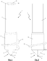
- the illustrated soil-displacement drills (1) comprise a drill pipe (3), a drill head (4) attached thereto and a closing element (6).
- the drill pipe (3) is substantially cylindrical and is provided with a displacer (11) at the bottom which is formed as a widening of the drill pipe (3).
- the drill pipe (3) is provided with a spiral (12) on its outside.
- the drill pipe (3) may be provided with one or several external spirals along its entire length.
- the drill pipe (3) may also be provided without said displacer (11) and/or without spirals.
- a cylindrical space (16) extends through the entire drill pipe (3). In specific embodiments, this cylindrical space (16) may be provided with one or several internal spirals.
- This drill pipe (3) may, for example, be made of metal. In the embodiment in Figs.
- the drill pipe (3) is cut off straight at the bottom end of the drill pipe (3) where the drill head (4) is attached, and has an end face which is virtually perpendicular to the direction of drilling.
- cams (22) project with respect to this end face.
- the illustrated drill heads (4) in each case comprise two flap leaves (5).
- a drill head (4) may also be provided with several flap leaves (5).
- each flap leaf (5) is hingedly attached to the drill pipe (3) by means of a hinge (9).
- this hinge (9) extends substantially inside a space in the pipe wall (15) of the drill pipe (3) in the closed position of the flap leaf (5).
- this pipe wall (15) is made sufficiently wide at the location of the displacer (11) in order to provide these spaces for the hidden hinges (9) which end at the said end of the drill pipe (3).
- this hinge (9) extends substantially inside a space (24) in the flap leaf (5) in the closed position of the flap leaf (5).
- an attachment body (25) is provided at the bottom of the displacer (11) for each flap leaf (5) and is arranged within the width of the pipe wall (15) of the displacer (11) and is bevelled in order to be able to extend substantially inside the space (24) in the flap leaf (5) in the closed position.
- a hinge pin (26) is arranged through this attachment body (25) and in the flap leaf (5) in order to attach this flap leaf (5) to this attachment body (25) so as to be able to pivot about this hinge pin (26).
- the flap leaves (5) are also provided with recesses (23) which correspond to the aforementioned cams (22) in such a way that the flap leaves (5), in their closed position, are secured with respect to these cams (22), this at the location where the flap leaves (5) adjoin each other.
- the drill head (4) tapers away from the drill pipe (3).
- the illustrated flap leaves (5) are of a shell-shaped design and together, in their closed position, form a substantially bit-shaped drill head (4).
- these flap leaves (5) preferably extend completely next to each other, without overlapping one another.
- these flap leaves (5) extend substantially inside the smallest surrounding cylinder of the drill pipe (3).
- each flap leaf (5) is provided with a drill tip part (8) away from the drill pipe (3).
- the drill tip parts (8) of both flap leaves (5) together form a drill tip (7).
- This drill tip (7) comprises a cylindrical base body (20) over which the closing element (6) is arrangeable in a clamping manner, and a conical tip (21).
- the closing element (6) is of annular design and made from plastic. To this end, this closing element (6) may be rigid or elastic.
- the closing element (6) comprises an annular base body (17) and four engagement elements (19) which are raised with respect to this base body (17).
- this closing element (6) is substantially cylindrical and comprises four virtually triangular incisions (18) which delimit the said engagement elements (19).
- this closing element (6) is clamped around the cylindrical base body (20) of the drill tip (7), as can be seen in Figs. 3, 4 and 8 .
- the engagement elements (19) project downwards, so that the surface (10) engages with these engagement elements (19) when drilling in a surface (10) in order to break and/or crack the annular base body (17) at the location of the incisions (18).
- this closing element (6) is preferably made of plastic by means of injection-moulding.
- a drill head (4) such as for example an illustrated drill head (4)
- a closing element (6) such as for example an illustrated closing element (6)
- a drill head (4) such as for example an illustrated drill head (4)
- a closing element (6) such as for example an illustrated closing element (6)
- an existing soil-displacement drill can be modified to form a soil-displacement drill (1) according to the present invention.
- the existing drill head of this existing soil-displacement drill may be removed and replaced by this new drill head (4).
- the closing element (6) may be provided on the outside of the flap leaves (5) of this new drill head (4) in order to keep these flap leaves (5) in their closed position.
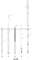
- Figs. 10a and 10b show how drilling in a surface (10) can take place by means of a soil-displacement drill (1) according to the present invention in order to form a foundation pile (2).
- the drill pipe (3) and the drill head (4), with the flap leaves (5) in their open position, are first lifted up (step A) to a height at which the flap leaves (5) can be closed easily and the closing element (6) can be fitted (step B). Thanks to the closing element (6), the flap leaves (5) in this soil-displacement drill (1) according to the present invention are easily held together when using it to drill in the surface (10) (step C).
- the drill (1) is lowered and drilled into the surface (10) (step D).
- the flap leaves (5) automatically remain closed during drilling to a deeper level. If the closing element (6) fails completely, the flap leaves (5) thus remain closed when drilling continues.
- the surface (10) is displaced laterally until the drill pipe (3) is situated in the surface (10) virtually completely (step E). Then, reinforcement (13) is introduced into the drill pipe (3) (step F) and the drill pipe (3) is filled with filling material (14) (step G), such as for example concrete.
- the closing element (6) is configured in such a way that this closing element (6), even if it does not fail completely, does not impede the flap leaves (5) from opening again when the soil-displacement drill (1) is drilled out of the soil again.
- Opening these flap leaves (5) may be effected in a simple manner on account of the filling material (14) and the reinforcement (13) when the soil-displacement drill (1) is lifted up.
- the drill pipe (3) is pulled out of the surface (10) (step H), with the reinforcement (13) and the filling material (14) remaining behind in the surface (10) to form the foundation pile (2) (step I).
Landscapes
- Engineering & Computer Science (AREA)
- Structural Engineering (AREA)
- General Engineering & Computer Science (AREA)
- Life Sciences & Earth Sciences (AREA)
- General Life Sciences & Earth Sciences (AREA)
- Mining & Mineral Resources (AREA)
- Paleontology (AREA)
- Civil Engineering (AREA)
- Piles And Underground Anchors (AREA)
- Earth Drilling (AREA)
Priority Applications (1)
| Application Number | Priority Date | Filing Date | Title |
|---|---|---|---|
| PL18759175T PL3523480T3 (pl) | 2017-10-20 | 2018-07-31 | Wiertnica wypierająca grunt, sposób przekształcenia wiertnicy wypierającej grunt i sposób formowania pala fundamentowego |
Applications Claiming Priority (2)
| Application Number | Priority Date | Filing Date | Title |
|---|---|---|---|
| BE2017/5752A BE1025657B1 (nl) | 2017-10-20 | 2017-10-20 | Grondverdringende boor en werkwijze voor het omvormen van een grondverdringende boor |
| PCT/IB2018/055710 WO2019077416A1 (en) | 2017-10-20 | 2018-07-31 | GROUND FLOW DRILLING TOOL, METHOD FOR CONVERTING FLOOR DRILLING TOOL AND METHOD FOR FORMING FOUNDATION PIE |
Publications (2)
| Publication Number | Publication Date |
|---|---|
| EP3523480A1 EP3523480A1 (en) | 2019-08-14 |
| EP3523480B1 true EP3523480B1 (en) | 2021-09-01 |
Family
ID=60320596
Family Applications (1)
| Application Number | Title | Priority Date | Filing Date |
|---|---|---|---|
| EP18759175.5A Active EP3523480B1 (en) | 2017-10-20 | 2018-07-31 | Soil-displacement drill, method for converting a soil-displacement drill and method for forming a foundation pile |
Country Status (10)
| Country | Link |
|---|---|
| US (2) | US11268255B2 (da) |
| EP (1) | EP3523480B1 (da) |
| AU (1) | AU2018352172B2 (da) |
| BE (1) | BE1025657B1 (da) |
| CA (1) | CA3075710C (da) |
| DK (1) | DK3523480T3 (da) |
| ES (1) | ES2898311T3 (da) |
| PL (1) | PL3523480T3 (da) |
| SG (1) | SG11202003085XA (da) |
| WO (1) | WO2019077416A1 (da) |
Families Citing this family (5)
| Publication number | Priority date | Publication date | Assignee | Title |
|---|---|---|---|---|
| BE1025657B1 (nl) * | 2017-10-20 | 2019-05-23 | Olivier Industrie Nv | Grondverdringende boor en werkwijze voor het omvormen van een grondverdringende boor |
| BE1027995B1 (nl) | 2020-01-16 | 2021-08-16 | Olivier Ind Nv | Grondverdringende boor en werkwijze voor het vormen van een gladde funderingspaal met een dergelijke grondverdringende boor |
| CN112077139B (zh) * | 2020-09-08 | 2022-02-22 | 生态环境部南京环境科学研究所 | 一种用于土壤异味处理的除臭装置及方法 |
| CN112854186B (zh) * | 2021-03-24 | 2022-02-11 | 广东新江永安建设工程有限公司 | 一种软土地基市政道路的处理方法 |
| WO2025199362A1 (en) * | 2024-03-20 | 2025-09-25 | Davie Warren | System and method for installing pilings using a removable helical tool |
Family Cites Families (15)
| Publication number | Priority date | Publication date | Assignee | Title |
|---|---|---|---|---|
| US779880A (en) * | 1904-04-12 | 1905-01-10 | Frank Shuman | Forming concrete piles and preparatory piles therefor. |
| US2576507A (en) * | 1949-02-14 | 1951-11-27 | Ben C Gerwick Inc | Hollow mandrel for placement of discrete material |
| IT949823B (it) * | 1972-03-02 | 1973-06-11 | Visconti B | Cassaforma per il getto in opera nel terreno di pali di fondazione |
| US4126007A (en) * | 1977-01-03 | 1978-11-21 | L.B. Foster Company | Compaction of soil |
| DE9002781U1 (de) * | 1990-03-09 | 1991-07-04 | Delmag Maschinenfabrik Reinhold Dornfeld GmbH & Co, 7300 Esslingen | Verdrängerbohrer |
| IT1254303B (it) * | 1992-02-07 | 1995-09-14 | Procedimento per la realizzazione di un micropalo per fondazioni di edifici adatto a terreni con caratteristiche meccaniche scadenti. | |
| KR100430342B1 (ko) * | 2001-07-25 | 2004-05-04 | 원 회 양 | 돌출간이 방사상으로 돌출된 현장 타설 콘크리트 파일형성장치 및 방법 |
| US6672408B2 (en) * | 2001-12-03 | 2004-01-06 | Anthony F. Frantz | System and apparatus for excavating contaminated pilings |
| US6668823B1 (en) * | 2002-12-27 | 2003-12-30 | Wen-Ho Liu | Diving mask allowing breath of a user with the nose |
| DE10310727B4 (de) * | 2003-03-12 | 2007-09-13 | Bauer Spezialtiefbau Gmbh | Füllrohr |
| DE10351956B3 (de) * | 2003-11-07 | 2005-07-14 | Josef Möbius Bau-Aktiengesellschaft | Vorrichtung zum Ausgreifen von Bodenmassen aus einem Rohr |
| NL2005298C2 (nl) | 2010-09-01 | 2012-03-05 | Jan Vos | Samenstel van buis en boorkop en werkwijze voor het vormen van een lichaam van materiaal in een bodem. |
| US20130177359A1 (en) * | 2011-05-02 | 2013-07-11 | North American Pile Driving Inc. | Method and Apparatus for Ground Improvement Using Compacted Aggregate Columns |
| EP3112535B1 (de) * | 2015-07-03 | 2018-01-10 | BAUER Spezialtiefbau GmbH | Füllrohr zum erstellen einer füllgutsäule im boden sowie vorrichtung und verfahren hierzu |
| BE1025657B1 (nl) * | 2017-10-20 | 2019-05-23 | Olivier Industrie Nv | Grondverdringende boor en werkwijze voor het omvormen van een grondverdringende boor |
-
2017
- 2017-10-20 BE BE2017/5752A patent/BE1025657B1/nl active IP Right Grant
-
2018
- 2018-07-31 WO PCT/IB2018/055710 patent/WO2019077416A1/en not_active Ceased
- 2018-07-31 EP EP18759175.5A patent/EP3523480B1/en active Active
- 2018-07-31 DK DK18759175.5T patent/DK3523480T3/da active
- 2018-07-31 ES ES18759175T patent/ES2898311T3/es active Active
- 2018-07-31 CA CA3075710A patent/CA3075710C/en active Active
- 2018-07-31 SG SG11202003085XA patent/SG11202003085XA/en unknown
- 2018-07-31 US US16/757,750 patent/US11268255B2/en active Active
- 2018-07-31 PL PL18759175T patent/PL3523480T3/pl unknown
- 2018-07-31 AU AU2018352172A patent/AU2018352172B2/en active Active
-
2022
- 2022-01-07 US US17/571,282 patent/US11655606B2/en active Active
Also Published As
| Publication number | Publication date |
|---|---|
| SG11202003085XA (en) | 2020-05-28 |
| CA3075710A1 (en) | 2019-04-25 |
| BE1025657A1 (nl) | 2019-05-16 |
| PL3523480T3 (pl) | 2022-01-10 |
| WO2019077416A1 (en) | 2019-04-25 |
| US11268255B2 (en) | 2022-03-08 |
| EP3523480A1 (en) | 2019-08-14 |
| BE1025657B1 (nl) | 2019-05-23 |
| US20210189676A1 (en) | 2021-06-24 |
| NZ762590A (en) | 2021-10-29 |
| US20220127809A1 (en) | 2022-04-28 |
| DK3523480T3 (da) | 2021-11-08 |
| US11655606B2 (en) | 2023-05-23 |
| AU2018352172A1 (en) | 2020-04-02 |
| AU2018352172B2 (en) | 2021-08-26 |
| CA3075710C (en) | 2022-08-30 |
| ES2898311T3 (es) | 2022-03-07 |
Similar Documents
| Publication | Publication Date | Title |
|---|---|---|
| US11655606B2 (en) | Soil-displacement drill, method for converting a soil-displacement drill and method for forming a foundation pile | |
| US10309155B2 (en) | Steering head | |
| JP5280257B2 (ja) | 基礎杭構造及び基礎杭の構築方法 | |
| NZ762590B2 (en) | Soil-displacement drill, method for converting a soil-displacement drill and method for forming a foundation pile | |
| JP3733772B2 (ja) | 場所打ち鋼管コンクリート杭とsrc柱との接合構造及びその接合方法 | |
| BE1027995B1 (nl) | Grondverdringende boor en werkwijze voor het vormen van een gladde funderingspaal met een dergelijke grondverdringende boor | |
| JP2009155961A (ja) | アースドリル機用ドリリングバケット | |
| JP5193084B2 (ja) | ドリリングバケット | |
| JP6963870B2 (ja) | 杭穴掘削ヘッド | |
| JP2010150761A (ja) | 杭穴掘削方法及び杭穴掘削ヘッド | |
| KR20150107035A (ko) | 플레이트 파일 기초를 이용한 데크 및 그 시공방법 | |
| JP2010043471A (ja) | 杭施工装置および杭施工方法 | |
| JP4196386B2 (ja) | 沈下防止機能を有する回転管状基礎 | |
| JPH0577840B2 (da) | ||
| JP6562831B2 (ja) | 土砂除去バケット及び土砂の除去方法 | |
| FR2892135A1 (fr) | Organe de liaison entre un micropieu et un outil d'enfoncement, installation de test a l'arrachement comprenant un tel organe | |
| US20060266910A1 (en) | Anchoring device | |
| AU2021207405C1 (en) | Soil-displacement drill and method for forming a smooth foundation pile with such a soil-displacement drill | |
| JP3219393U (ja) | 中掘り杭工法用雇い杭 | |
| JPH0236754B2 (da) | ||
| KR101670825B1 (ko) | 현장타설말뚝용 하부 확대형 보강재 및 이를 이용한 현장타설말뚝 공법 | |
| JPH066862B2 (ja) | アースオーガ装置に使用する掘削ヘッド |
Legal Events
| Date | Code | Title | Description |
|---|---|---|---|
| STAA | Information on the status of an ep patent application or granted ep patent |
Free format text: STATUS: UNKNOWN |
|
| STAA | Information on the status of an ep patent application or granted ep patent |
Free format text: STATUS: THE INTERNATIONAL PUBLICATION HAS BEEN MADE |
|
| PUAI | Public reference made under article 153(3) epc to a published international application that has entered the european phase |
Free format text: ORIGINAL CODE: 0009012 |
|
| STAA | Information on the status of an ep patent application or granted ep patent |
Free format text: STATUS: REQUEST FOR EXAMINATION WAS MADE |
|
| 17P | Request for examination filed |
Effective date: 20190508 |
|
| AK | Designated contracting states |
Kind code of ref document: A1 Designated state(s): AL AT BE BG CH CY CZ DE DK EE ES FI FR GB GR HR HU IE IS IT LI LT LU LV MC MK MT NL NO PL PT RO RS SE SI SK SM TR |
|
| AX | Request for extension of the european patent |
Extension state: BA ME |
|
| STAA | Information on the status of an ep patent application or granted ep patent |
Free format text: STATUS: EXAMINATION IS IN PROGRESS |
|
| 17Q | First examination report despatched |
Effective date: 20200407 |
|
| DAV | Request for validation of the european patent (deleted) | ||
| DAX | Request for extension of the european patent (deleted) | ||
| GRAP | Despatch of communication of intention to grant a patent |
Free format text: ORIGINAL CODE: EPIDOSNIGR1 |
|
| STAA | Information on the status of an ep patent application or granted ep patent |
Free format text: STATUS: GRANT OF PATENT IS INTENDED |
|
| INTG | Intention to grant announced |
Effective date: 20210322 |
|
| GRAS | Grant fee paid |
Free format text: ORIGINAL CODE: EPIDOSNIGR3 |
|
| GRAA | (expected) grant |
Free format text: ORIGINAL CODE: 0009210 |
|
| STAA | Information on the status of an ep patent application or granted ep patent |
Free format text: STATUS: THE PATENT HAS BEEN GRANTED |
|
| RIN1 | Information on inventor provided before grant (corrected) |
Inventor name: VANKEIRSBILCK, DIMITRI Inventor name: VANKEIRSBILCK, GERDI |
|
| AK | Designated contracting states |
Kind code of ref document: B1 Designated state(s): AL AT BE BG CH CY CZ DE DK EE ES FI FR GB GR HR HU IE IS IT LI LT LU LV MC MK MT NL NO PL PT RO RS SE SI SK SM TR |
|
| REG | Reference to a national code |
Ref country code: GB Ref legal event code: FG4D |
|
| REG | Reference to a national code |
Ref country code: CH Ref legal event code: EP Ref country code: AT Ref legal event code: REF Ref document number: 1426388 Country of ref document: AT Kind code of ref document: T Effective date: 20210915 |
|
| REG | Reference to a national code |
Ref country code: DE Ref legal event code: R096 Ref document number: 602018022941 Country of ref document: DE |
|
| REG | Reference to a national code |
Ref country code: IE Ref legal event code: FG4D |
|
| REG | Reference to a national code |
Ref country code: DK Ref legal event code: T3 Effective date: 20211104 |
|
| REG | Reference to a national code |
Ref country code: FI Ref legal event code: FGE |
|
| REG | Reference to a national code |
Ref country code: SE Ref legal event code: TRGR |
|
| REG | Reference to a national code |
Ref country code: LT Ref legal event code: MG9D |
|
| REG | Reference to a national code |
Ref country code: NL Ref legal event code: FP |
|
| REG | Reference to a national code |
Ref country code: NO Ref legal event code: T2 Effective date: 20210901 |
|
| PG25 | Lapsed in a contracting state [announced via postgrant information from national office to epo] |
Ref country code: LT Free format text: LAPSE BECAUSE OF FAILURE TO SUBMIT A TRANSLATION OF THE DESCRIPTION OR TO PAY THE FEE WITHIN THE PRESCRIBED TIME-LIMIT Effective date: 20210901 Ref country code: BG Free format text: LAPSE BECAUSE OF FAILURE TO SUBMIT A TRANSLATION OF THE DESCRIPTION OR TO PAY THE FEE WITHIN THE PRESCRIBED TIME-LIMIT Effective date: 20211201 Ref country code: RS Free format text: LAPSE BECAUSE OF FAILURE TO SUBMIT A TRANSLATION OF THE DESCRIPTION OR TO PAY THE FEE WITHIN THE PRESCRIBED TIME-LIMIT Effective date: 20210901 Ref country code: HR Free format text: LAPSE BECAUSE OF FAILURE TO SUBMIT A TRANSLATION OF THE DESCRIPTION OR TO PAY THE FEE WITHIN THE PRESCRIBED TIME-LIMIT Effective date: 20210901 |
|
| PG25 | Lapsed in a contracting state [announced via postgrant information from national office to epo] |
Ref country code: LV Free format text: LAPSE BECAUSE OF FAILURE TO SUBMIT A TRANSLATION OF THE DESCRIPTION OR TO PAY THE FEE WITHIN THE PRESCRIBED TIME-LIMIT Effective date: 20210901 Ref country code: GR Free format text: LAPSE BECAUSE OF FAILURE TO SUBMIT A TRANSLATION OF THE DESCRIPTION OR TO PAY THE FEE WITHIN THE PRESCRIBED TIME-LIMIT Effective date: 20211202 |
|
| REG | Reference to a national code |
Ref country code: ES Ref legal event code: FG2A Ref document number: 2898311 Country of ref document: ES Kind code of ref document: T3 Effective date: 20220307 |
|
| PG25 | Lapsed in a contracting state [announced via postgrant information from national office to epo] |
Ref country code: IS Free format text: LAPSE BECAUSE OF FAILURE TO SUBMIT A TRANSLATION OF THE DESCRIPTION OR TO PAY THE FEE WITHIN THE PRESCRIBED TIME-LIMIT Effective date: 20220101 Ref country code: SM Free format text: LAPSE BECAUSE OF FAILURE TO SUBMIT A TRANSLATION OF THE DESCRIPTION OR TO PAY THE FEE WITHIN THE PRESCRIBED TIME-LIMIT Effective date: 20210901 Ref country code: SK Free format text: LAPSE BECAUSE OF FAILURE TO SUBMIT A TRANSLATION OF THE DESCRIPTION OR TO PAY THE FEE WITHIN THE PRESCRIBED TIME-LIMIT Effective date: 20210901 Ref country code: RO Free format text: LAPSE BECAUSE OF FAILURE TO SUBMIT A TRANSLATION OF THE DESCRIPTION OR TO PAY THE FEE WITHIN THE PRESCRIBED TIME-LIMIT Effective date: 20210901 Ref country code: PT Free format text: LAPSE BECAUSE OF FAILURE TO SUBMIT A TRANSLATION OF THE DESCRIPTION OR TO PAY THE FEE WITHIN THE PRESCRIBED TIME-LIMIT Effective date: 20220103 Ref country code: EE Free format text: LAPSE BECAUSE OF FAILURE TO SUBMIT A TRANSLATION OF THE DESCRIPTION OR TO PAY THE FEE WITHIN THE PRESCRIBED TIME-LIMIT Effective date: 20210901 Ref country code: CZ Free format text: LAPSE BECAUSE OF FAILURE TO SUBMIT A TRANSLATION OF THE DESCRIPTION OR TO PAY THE FEE WITHIN THE PRESCRIBED TIME-LIMIT Effective date: 20210901 Ref country code: AL Free format text: LAPSE BECAUSE OF FAILURE TO SUBMIT A TRANSLATION OF THE DESCRIPTION OR TO PAY THE FEE WITHIN THE PRESCRIBED TIME-LIMIT Effective date: 20210901 |
|
| REG | Reference to a national code |
Ref country code: DE Ref legal event code: R097 Ref document number: 602018022941 Country of ref document: DE |
|
| PLBE | No opposition filed within time limit |
Free format text: ORIGINAL CODE: 0009261 |
|
| STAA | Information on the status of an ep patent application or granted ep patent |
Free format text: STATUS: NO OPPOSITION FILED WITHIN TIME LIMIT |
|
| 26N | No opposition filed |
Effective date: 20220602 |
|
| PG25 | Lapsed in a contracting state [announced via postgrant information from national office to epo] |
Ref country code: SI Free format text: LAPSE BECAUSE OF FAILURE TO SUBMIT A TRANSLATION OF THE DESCRIPTION OR TO PAY THE FEE WITHIN THE PRESCRIBED TIME-LIMIT Effective date: 20210901 |
|
| PG25 | Lapsed in a contracting state [announced via postgrant information from national office to epo] |
Ref country code: MC Free format text: LAPSE BECAUSE OF FAILURE TO SUBMIT A TRANSLATION OF THE DESCRIPTION OR TO PAY THE FEE WITHIN THE PRESCRIBED TIME-LIMIT Effective date: 20210901 |
|
| REG | Reference to a national code |
Ref country code: AT Ref legal event code: UEP Ref document number: 1426388 Country of ref document: AT Kind code of ref document: T Effective date: 20210901 |
|
| PG25 | Lapsed in a contracting state [announced via postgrant information from national office to epo] |
Ref country code: LU Free format text: LAPSE BECAUSE OF NON-PAYMENT OF DUE FEES Effective date: 20220731 |
|
| P01 | Opt-out of the competence of the unified patent court (upc) registered |
Effective date: 20230509 |
|
| PG25 | Lapsed in a contracting state [announced via postgrant information from national office to epo] |
Ref country code: HU Free format text: LAPSE BECAUSE OF FAILURE TO SUBMIT A TRANSLATION OF THE DESCRIPTION OR TO PAY THE FEE WITHIN THE PRESCRIBED TIME-LIMIT; INVALID AB INITIO Effective date: 20180731 |
|
| PG25 | Lapsed in a contracting state [announced via postgrant information from national office to epo] |
Ref country code: MK Free format text: LAPSE BECAUSE OF FAILURE TO SUBMIT A TRANSLATION OF THE DESCRIPTION OR TO PAY THE FEE WITHIN THE PRESCRIBED TIME-LIMIT Effective date: 20210901 Ref country code: CY Free format text: LAPSE BECAUSE OF FAILURE TO SUBMIT A TRANSLATION OF THE DESCRIPTION OR TO PAY THE FEE WITHIN THE PRESCRIBED TIME-LIMIT Effective date: 20210901 |
|
| PG25 | Lapsed in a contracting state [announced via postgrant information from national office to epo] |
Ref country code: MT Free format text: LAPSE BECAUSE OF FAILURE TO SUBMIT A TRANSLATION OF THE DESCRIPTION OR TO PAY THE FEE WITHIN THE PRESCRIBED TIME-LIMIT Effective date: 20210901 |
|
| PGFP | Annual fee paid to national office [announced via postgrant information from national office to epo] |
Ref country code: PL Payment date: 20250618 Year of fee payment: 8 |
|
| PGFP | Annual fee paid to national office [announced via postgrant information from national office to epo] |
Ref country code: NL Payment date: 20250721 Year of fee payment: 8 |
|
| PGFP | Annual fee paid to national office [announced via postgrant information from national office to epo] |
Ref country code: ES Payment date: 20250826 Year of fee payment: 8 Ref country code: FI Payment date: 20250725 Year of fee payment: 8 |
|
| PGFP | Annual fee paid to national office [announced via postgrant information from national office to epo] |
Ref country code: DE Payment date: 20250722 Year of fee payment: 8 Ref country code: DK Payment date: 20250725 Year of fee payment: 8 |
|
| PGFP | Annual fee paid to national office [announced via postgrant information from national office to epo] |
Ref country code: NO Payment date: 20250725 Year of fee payment: 8 |
|
| PGFP | Annual fee paid to national office [announced via postgrant information from national office to epo] |
Ref country code: TR Payment date: 20250722 Year of fee payment: 8 Ref country code: IT Payment date: 20250724 Year of fee payment: 8 |
|
| PGFP | Annual fee paid to national office [announced via postgrant information from national office to epo] |
Ref country code: BE Payment date: 20250718 Year of fee payment: 8 Ref country code: GB Payment date: 20250722 Year of fee payment: 8 |
|
| PGFP | Annual fee paid to national office [announced via postgrant information from national office to epo] |
Ref country code: FR Payment date: 20250725 Year of fee payment: 8 Ref country code: AT Payment date: 20250722 Year of fee payment: 8 |
|
| PGFP | Annual fee paid to national office [announced via postgrant information from national office to epo] |
Ref country code: CH Payment date: 20250801 Year of fee payment: 8 Ref country code: SE Payment date: 20250722 Year of fee payment: 8 |
|
| PGFP | Annual fee paid to national office [announced via postgrant information from national office to epo] |
Ref country code: IE Payment date: 20250723 Year of fee payment: 8 |